
Chapter 11. Tuning a Red Hat OpenStack Platform environment
11.1. Pinning emulator threads
Emulator threads handle interrupt requests and non-blocking processes for virtual machine hardware emulation. These threads float across the CPUs that the guest uses for processing. If threads used for the poll mode driver (PMD) or real-time processing run on these guest CPUs, you can experience packet loss or missed deadlines.
You can separate emulator threads from VM processing tasks by pinning the threads to their own guest CPUs, increasing performance as a result.
To improve performance, reserve a subset of host CPUs for hosting emulator threads.
Procedure
Deploy an overcloud with
NovaComputeCpuSharedSetdefined for a given role. The value ofNovaComputeCpuSharedSetapplies to thecpu_shared_setparameter in thenova.conffile for hosts within that role.parameter_defaults: ComputeOvsDpdkParameters: NovaComputeCpuSharedSet: "0-1,16-17" NovaComputeCpuDedicatedSet: "2-15,18-31"Create a flavor to build instances with emulator threads separated into a shared pool.
openstack flavor create --ram <size_mb> --disk <size_gb> --vcpus <vcpus> <flavor>
Add the
hw:emulator_threads_policyextra specification, and set the value toshare. Instances created with this flavor will use the instance CPUs defined in thecpu_share_setparameter in the nova.conf file.openstack flavor set <flavor> --property hw:emulator_threads_policy=share
You must set the cpu_share_set parameter in the nova.conf file to enable the share policy for this extra specification. You should use heat for this preferably, as editing nova.conf manually might not persist across redeployments.
Verification
Identify the host and name for a given instance.
openstack server show <instance_id>
Use SSH to log on to the identified host as tripleo-admin.
ssh tripleo-admin@compute-1
[compute-1]$ sudo virsh dumpxml instance-00001 | grep `'emulatorpin cpuset'`
11.2. Configuring trust between virtual and physical functions
You can configure trust between physical functions (PFs) and virtual functions (VFs), so that VFs can perform privileged actions, such as enabling promiscuous mode, or modifying a hardware address.
Prerequisites
- An operational installation of Red Hat OpenStack Platform including director
Procedure
Complete the following steps to configure and deploy the overcloud with trust between physical and virtual functions:
Add the
NeutronPhysicalDevMappingsparameter in theparameter_defaultssection to link between the logical network name and the physical interface.parameter_defaults: NeutronPhysicalDevMappings: - sriov2:p5p2Add the new property,
trusted, to the SR-IOV parameters.parameter_defaults: NeutronPhysicalDevMappings: - sriov2:p5p2 NovaPCIPassthrough: - vendor_id: "8086" product_id: "1572" physical_network: "sriov2" trusted: "true"NoteYou must include double quotation marks around the value "true".
11.3. Utilizing trusted VF networks
Create a network of type
vlan.openstack network create trusted_vf_network --provider-network-type vlan \ --provider-segment 111 --provider-physical-network sriov2 \ --external --disable-port-security
Create a subnet.
openstack subnet create --network trusted_vf_network \
  --ip-version 4 --subnet-range 192.168.111.0/24 --no-dhcp \
 subnet-trusted_vf_network
Create a port. Set the
vnic-typeoption todirect, and thebinding-profileoption totrue.openstack port create --network sriov111 \ --vnic-type direct --binding-profile trusted=true \ sriov111_port_trusted
Create an instance, and bind it to the previously-created trusted port.
openstack server create --image rhel --flavor dpdk --network internal --port trusted_vf_network_port_trusted --config-drive True --wait rhel-dpdk-sriov_trusted
Verification
Confirm the trusted VF configuration on the hypervisor:
On the compute node that you created the instance, enter the following command:
# ip link 7: p5p2: <BROADCAST,MULTICAST,UP,LOWER_UP> mtu 9000 qdisc mq state UP mode DEFAULT group default qlen 1000 link/ether b4:96:91:1c:40:fa brd ff:ff:ff:ff:ff:ff vf 6 MAC fa:16:3e:b8:91:c2, vlan 111, spoof checking off, link-state auto, trust on, query_rss off vf 7 MAC fa:16:3e:84:cf:c8, vlan 111, spoof checking off, link-state auto, trust off, query_rss off-
Verify that the trust status of the VF is
trust on. The example output contains details of an environment that contains two ports. Note thatvf 6contains the texttrust on. -
You can disable spoof checking if you set
port_security_enabled: falsein the Networking service (neutron) network, or if you include the argument--disable-port-securitywhen you run theopenstack port createcommand.
11.4. Preventing packet loss by managing RX-TX queue size
You can experience packet loss at high packet rates above 3.5 million packets per second (mpps) for many reasons, such as:
- a network interrupt
- a SMI
- packet processing latency in the Virtual Network Function
To prevent packet loss, increase the queue size from the default of 512 to a maximum of 1024.
Prerequisites
-
Access to the undercloud host and credentials for the
stackuser.
Procedure
-
Log in to the undercloud host as the
stackuser. Source the
stackrcundercloud credentials file:$ source ~/stackrc
Create a custom environment YAML file and under
parameter_defaultsadd the following definitions to increase the RX and TX queue size:parameter_defaults: NovaLibvirtRxQueueSize: 1024 NovaLibvirtTxQueueSize: 1024
Run the deployment command and include the core heat templates, other environment files, the environment file that contains your RX and TX queue size changes:
Example
$ openstack overcloud deploy --templates \
-e <other_environment_files> \
-e /home/stack/my_tx-rx_queue_sizes.yaml
Verification
Observe the values for RX queue size and TX queue size in the
nova.conffile.$ egrep "^[rt]x_queue_size" /var/lib/config-data/puppet-generated/\ nova_libvirt/etc/nova/nova.conf
You should see the following:
rx_queue_size=1024
tx_queue_size=1024
Check the values for RX queue size and TX queue size in the VM instance XML file generated by libvirt on the Compute host:
- Create a new instance.
Obtain the Compute host and and instance name:
$ openstack server show testvm-queue-sizes -c OS-EXT-SRV-ATTR:\
hypervisor_hostname -c OS-EXT-SRV-ATTR:instance_name
Sample output
You should see output similar to the following:
+-------------------------------------+------------------------------------+
| Field                               | Value                              |
+-------------------------------------+------------------------------------+
| OS-EXT-SRV-ATTR:hypervisor_hostname | overcloud-novacompute-1.sales      |
| OS-EXT-SRV-ATTR:instance_name       | instance-00000059                  |
+-------------------------------------+------------------------------------+
Log into the Compute host and dump the instance definition.
Example
$ podman exec nova_libvirt virsh dumpxml instance-00000059
Sample output
You should see output similar to the following:
...
   <interface type='vhostuser'>
     <mac address='56:48:4f:4d:5e:6f'/>
     <source type='unix' path='/tmp/vhost-user1' mode='server'/>
     <model type='virtio'/>
     <driver name='vhost' rx_queue_size='1024'   tx_queue_size='1024' />
     <address type='pci' domain='0x0000' bus='0x00' slot='0x10' function='0x0'/>
   </interface>
...
11.5. Configuring a NUMA-aware vSwitch
This feature is available in this release as a Technology Preview, and therefore is not fully supported by Red Hat. It should only be used for testing, and should not be deployed in a production environment. For more information about Technology Preview features, see Scope of Coverage Details.
Before you implement a NUMA-aware vSwitch, examine the following components of your hardware configuration:
- The number of physical networks.
- The placement of PCI cards.
- The physical architecture of the servers.
Memory-mapped I/O (MMIO) devices, such as PCIe NICs, are associated with specific NUMA nodes. When a VM and the NIC are on different NUMA nodes, there is a significant decrease in performance. To increase performance, align PCIe NIC placement and instance processing on the same NUMA node.
Use this feature to ensure that instances that share a physical network are located on the same NUMA node. To optimize utilization of datacenter hardware, you must use multiple physnets.
To configure NUMA-aware networks for optimal server utilization, you must understand the mapping of the PCIe slot and the NUMA node. For detailed information on your specific hardware, refer to your vendor’s documentation. If you fail to plan or implement your NUMA-aware vSwitch correctly, you can cause the servers to use only a single NUMA node.
To prevent a cross-NUMA configuration, place the VM on the correct NUMA node, by providing the location of the NIC to Nova.
Prerequisites
-
You have enabled the filter
NUMATopologyFilter.
Procedure
-
Set a new
NeutronPhysnetNUMANodesMappingparameter to map the physical network to the NUMA node that you associate with the physical network. If you use tunnels, such as VxLAN or GRE, you must also set the
NeutronTunnelNUMANodesparameter.parameter_defaults: NeutronPhysnetNUMANodesMapping: {<physnet_name>: [<NUMA_NODE>]} NeutronTunnelNUMANodes: <NUMA_NODE>,<NUMA_NODE>Example
Here is an example with two physical networks tunneled to NUMA node 0:
- one project network associated with NUMA node 0
one management network without any affinity
parameter_defaults:
  NeutronBridgeMappings:
    - tenant:br-link0
  NeutronPhysnetNUMANodesMapping: {tenant: [1], mgmt: [0,1]}
  NeutronTunnelNUMANodes: 0
In this example, assign the physnet of the device named
eno2to NUMA number 0.# ethtool -i eno2 bus-info: 0000:18:00.1 # cat /sys/devices/pci0000:16/0000:16:02.0/0000:18:00.1/numa_node 0
Observe the physnet settings in the example heat template:
NeutronBridgeMappings: 'physnet1:br-physnet1'
NeutronPhysnetNUMANodesMapping: {physnet1: [0] }

- type: ovs_user_bridge
                name: br-physnet1
                mtu: 9000
                members:
                  - type: ovs_dpdk_port
                    name: dpdk2
                    members:
                      - type: interface
                        name: eno2
Verification
Follow these steps to test your NUMA-aware vSwitch:
Observe the configuration in the file
/var/lib/config-data/puppet-generated/nova_libvirt/etc/nova/nova.conf:[neutron_physnet_tenant] numa_nodes=1 [neutron_tunnel] numa_nodes=1
Confirm the new configuration with the
lscpucommand:$ lscpu
- Launch a VM with the NIC attached to the appropriate network.
11.6. Known limitations for NUMA-aware vSwitches
This feature is available in this release as a Technology Preview, and therefore is not fully supported by Red Hat. It should only be used for testing, and should not be deployed in a production environment. For more information about Technology Preview features, see Scope of Coverage Details.
This section lists the constraints for implementing a NUMA-aware vSwitch in a Red Hat OpenStack Platform (RHOSP) network functions virtualization infrastructure (NFVi).
- You cannot start a VM that has two NICs connected to physnets on different NUMA nodes, if you did not specify a two-node guest NUMA topology.
- You cannot start a VM that has one NIC connected to a physnet and another NIC connected to a tunneled network on different NUMA nodes, if you did not specify a two-node guest NUMA topology.
- You cannot start a VM that has one vhost port and one VF on different NUMA nodes, if you did not specify a two-node guest NUMA topology.
- NUMA-aware vSwitch parameters are specific to overcloud roles. For example, Compute node 1 and Compute node 2 can have different NUMA topologies.
- If the interfaces of a VM have NUMA affinity, ensure that the affinity is for a single NUMA node only. You can locate any interface without NUMA affinity on any NUMA node.
- Configure NUMA affinity for data plane networks, not management networks.
- NUMA affinity for tunneled networks is a global setting that applies to all VMs.
11.7. Quality of Service (QoS) in NFVi environments
You can offer varying service levels for VM instances by using quality of service (QoS) policies to apply rate limits to egress and ingress traffic on Red Hat OpenStack Platform (RHOSP) networks in a network functions virtualization infrastructure (NFVi).
In NFVi environments, QoS support is limited to the following rule types:
-
minimum bandwidthon SR-IOV, if supported by vendor. -
bandwidth limiton SR-IOV and OVS-DPDK egress interfaces.
Additional resources
11.8. Creating an HCI overcloud that uses DPDK
You can deploy your NFV infrastructure with hyperconverged nodes, by co-locating and configuring Compute and Ceph Storage services for optimized resource usage.
For more information about hyper-converged infrastructure (HCI), see Deploying a hyperconverged infrastructure.
The sections that follow provide examples of various configurations.
11.8.1. Example NUMA node configuration
For increased performance, place the tenant network and Ceph object service daemon (OSD)s in one NUMA node, such as NUMA-0, and the VNF and any non-NFV VMs in another NUMA node, such as NUMA-1.
CPU allocation:
| NUMA-0 | NUMA-1 |
|---|---|
| Number of Ceph OSDs * 4 HT | Guest vCPU for the VNF and non-NFV VMs |
| DPDK lcore - 2 HT | DPDK lcore - 2 HT |
| DPDK PMD - 2 HT | DPDK PMD - 2 HT |
Example of CPU allocation:
| NUMA-0 | NUMA-1 | |
|---|---|---|
| Ceph OSD | 32,34,36,38,40,42,76,78,80,82,84,86 | |
| DPDK-lcore | 0,44 | 1,45 |
| DPDK-pmd | 2,46 | 3,47 |
| nova | 5,7,9,11,13,15,17,19,21,23,25,27,29,31,33,35,37,39,41,43,49,51,53,55,57,59,61,63,65,67,69,71,73,75,77,79,81,83,85,87 |
11.8.2. Example Ceph configuration file
This section describes a sample Red Hat Ceph Storage configuration file. You can model your configuration file on this one, by substituting values that are appropriate for your Red Hat OpenStack Platform environment.
[osd]
osd_numa_node = 0                              # 1
osd_memory_target_autotune = true              # 2

[mgr]
mgr/cephadm/autotune_memory_target_ratio = 0.2 # 3
Assign CPU resources for Ceph Object Storage Daemons (OSDs) processes with the following parameters. The values shown here are examples. Adjust the values as appropriate based on your workload and hardware.
- 1
osd_numa_node: sets the affinity of Ceph processes to a NUMA node, for example,0forNUMA-0,1forNUMA-1, and so on.-1sets the affinity to no NUMA node.In this example,
osd_numa_nodeis set toNUMA-0. As shown in Section 11.8.3, “Example DPDK configuration file”,IsolCpusListcontains odd numbered CPUs onNUMA-1, after elements ofOvsPmdCoreListare removed. Because the latency-sensitive Compute service (nova) workload is hosted onNUMA-1, you must isolate the Ceph workload onNUMA-0. This example assumes that both the disk controllers and network interfaces for the stroage network are onNUMA-0.- 2
osd_memory_target_autotune: when set to true, the OSD daemons adjust their memory consumption based on theosd_memory_targetconfiguration option.- 3
autotune_memory_target_ratio: used to allocate memory for OSDs. The default is0.7.70% of the total RAM in the system is the starting point, from which any memory consumed by non-autotuned Ceph daemons are subtracted. When
osd_memory_target_autotuneis true for all OSDs, the remaining memory is divided by the OSDs. For HCI deployments themgr/cephadm/autotune_memory_target_ratiocan be set to0.2so that more memory is available for the Compute service. Adjust as needed to ensure each OSD has at least 5 GB of memory.
Additional resources
11.8.3. Example DPDK configuration file
parameter_defaults:
  ComputeHCIParameters:
    KernelArgs: "default_hugepagesz=1GB hugepagesz=1G hugepages=240 intel_iommu=on iommu=pt                                           # 1
      isolcpus=2,46,3,47,5,7,9,11,13,15,17,19,21,23,25,27,29,31,33,35,37,39,41,43,49,51,53,55,57,59,61,63,65,67,69,71,73,75,77,79,81,83,85,87"
    TunedProfileName: "cpu-partitioning"
    IsolCpusList:                                               # 2
      ”2,46,3,47,5,7,9,11,13,15,17,19,21,23,25,27,29,31,33,35,37,39,41,43,49,51,
      53,55,57,59,61,63,65,67,69,71,73,75,77,79,81,83,85,87"
    VhostuserSocketGroup: hugetlbfs
    OvsDpdkSocketMemory: "4096,4096"                            # 3
    OvsDpdkMemoryChannels: "4"

OvsPmdCoreList: "2,46,3,47" # 4- 1
- KernelArgs: To calculate
hugepages, subtract the value of theNovaReservedHostMemoryparameter from total memory. - 2
- IsolCpusList: Assign a set of CPU cores that you want to isolate from the host processes with this parameter. Add the value of the
OvsPmdCoreListparameter to the value of theNovaComputeCpuDedicatedSetparameter to calculate the value for theIsolCpusListparameter. - 3
- OvsDpdkSocketMemory: Specify the amount of memory in MB to pre-allocate from the hugepage pool per NUMA node with the
OvsDpdkSocketMemoryparameter. For more information about calculating OVS-DPDK parameters, see OVS-DPDK parameters. - 4
- OvsPmdCoreList: Specify the CPU cores that are used for the DPDK poll mode drivers (PMD) with this parameter. Choose CPU cores that are associated with the local NUMA nodes of the DPDK interfaces. Allocate 2 HT sibling threads for each NUMA node to calculate the value for the
OvsPmdCoreListparameter.
11.8.4. Example nova configuration file
parameter_defaults:
  ComputeHCIExtraConfig:
    nova::cpu_allocation_ratio: 16 # 2
    NovaReservedHugePages:                                         # 1
        - node:0,size:1GB,count:4
        - node:1,size:1GB,count:4
  NovaReservedHostMemory: 123904                                   # 2
  # All left over cpus from NUMA-1
  NovaComputeCpuDedicatedSet:                                                  # 3
  ['5','7','9','11','13','15','17','19','21','23','25','27','29','31','33','35','37','39','41','43','49','51','|
53','55','57','59','61','63','65','67','69','71','73','75','77','79','81','83','85','87- 1
- NovaReservedHugePages: Pre-allocate memory in MB from the hugepage pool with the
NovaReservedHugePagesparameter. It is the same memory total as the value for theOvsDpdkSocketMemoryparameter. - 2
- NovaReservedHostMemory: Reserve memory in MB for tasks on the host with the
NovaReservedHostMemoryparameter. Use the following guidelines to calculate the amount of memory that you must reserve:- 5 GB for each OSD.
- 0.5 GB overhead for each VM.
- 4GB for general host processing. Ensure that you allocate sufficient memory to prevent potential performance degradation caused by cross-NUMA OSD operation.
- 3
- NovaComputeCpuDedicatedSet: List the CPUs not found in
OvsPmdCoreList, orCeph_osd_docker_cpuset_cpuswith theNovaComputeCpuDedicatedSetparameter. The CPUs must be in the same NUMA node as the DPDK NICs.
11.8.5. Recommended configuration for HCI-DPDK deployments
Table 11.1. Tunable parameters for HCI deployments
| Block Device Type | OSDs, Memory, vCPUs per device |
|---|---|
| NVMe |
Memory : 5GB per OSD |
| SSD |
Memory : 5GB per OSD |
| HDD |
Memory : 5GB per OSD |
Use the same NUMA node for the following functions:
- Disk controller
- Storage networks
- Storage CPU and memory
Allocate another NUMA node for the following functions of the DPDK provider network:
- NIC
- PMD CPUs
- Socket memory
11.8.6. Deploying the HCI-DPDK overcloud
Follow these steps to deploy a hyperconverged overcloud that uses DPDK.
Prerequisites
- Red Hat OpenStack Platform (RHOSP) 17.1 or later.
- The latest version of Red Hat Ceph Storage 6.1.
Procedure
Generate the
roles_data.yamlfile for the Controller and the ComputeHCIOvsDpdk roles.$ openstack overcloud roles generate -o ~/<templates>/roles_data.yaml \ Controller ComputeHCIOvsDpdk
-
Create and configure a new flavor with the
openstack flavor createandopenstack flavor setcommands. Deploy Ceph by using RHOSP director and the Ceph configuration file.
Example
$ openstack overcloud ceph deploy --config initial-ceph.conf
Deploy the overcloud with the custom
roles_data.yamlfile that you generated.Example
$ openstack overcloud deploy --templates \
  --timeout 360 \
  -r ~/<templates>/roles_data.yaml \
  -e /usr/share/openstack-tripleo-heat-templates/environments/\
  cephadm/cephadm-rbd-only.yaml \
  -e /usr/share/openstack-tripleo-heat-templates/environments/network-isolation.yaml \
  -e /usr/share/openstack-tripleo-heat-templates/environments/services-docker/neutron-ovs-dpdk.yaml \
  -e ~/<templates>/<custom environment file>
ImportantThis example deploys Ceph RBD (block storage) without Ceph RGW (object storage). To include RGW in the deployment, use
cephadm.yamlinstead ofcephadm-rbd-only.yaml.
Additional resources
- Composable services and custom roles in Customizing your Red Hat OpenStack Platform deployment
- Section 11.8.2, “Example Ceph configuration file”
- Configuring the Red Hat Ceph Storage cluster in Deploying Red Hat Ceph Storage and Red Hat OpenStack Platform together with director.
11.9. Synchronize your compute nodes with Timemaster
This feature is available in this release as a Technology Preview, and therefore is not fully supported by Red Hat. It should only be used for testing, and should not be deployed in a production environment. For more information about Technology Preview features, see Scope of Coverage Details.
Use time protocols to maintain a consistent timestamp between systems.
Red Hat OpenStack Platform (RHOSP) includes support for Precision Time Protocol (PTP) and Network Time Protocol (NTP).
You can use NTP to synchronize clocks in your network in the millisecond range, and you can use PTP to synchronize clocks to a higher, sub-microsecond, accuracy. An example use case for PTP is a virtual radio access network (vRAN) that contains multiple antennas which provide higher throughput with more risk of interference.
Timemaster is a program that uses ptp4l and phc2sys in combination with chronyd or ntpd to synchronize the system clock to NTP and PTP time sources. The phc2sys and ptp4l programs use Shared Memory Driver (SHM) reference clocks to send PTP time to chronyd or ntpd, which compares the time sources to synchronize the system clock.
The implementation of the PTPv2 protocol in the Red Hat Enterprise Linux (RHEL) kernel is linuxptp.
The linuxptp package includes the ptp4l program for PTP boundary clock and ordinary clock synchronization, and the phc2sys program for hardware time stamping. For more information about PTP, see: Introduction to PTP in the Red Hat Enterprise Linux System Administrator’s Guide.
Chrony is an implementation of the NTP protocol. The two main components of Chrony are chronyd, which is the Chrony daemon, and chronyc which is the Chrony command line interface.
For more information about Chrony, see Using the Chrony suite to configure NTP in the Red Hat Enterprise Linux System Administrator’s Guide.
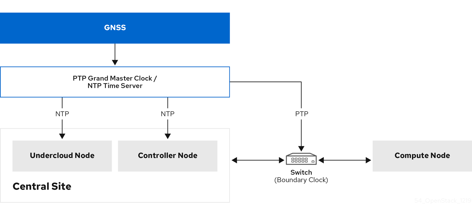
The following image is an overview of a packet journey in a PTP configuration.
Figure 11.1. PTP packet journey overview
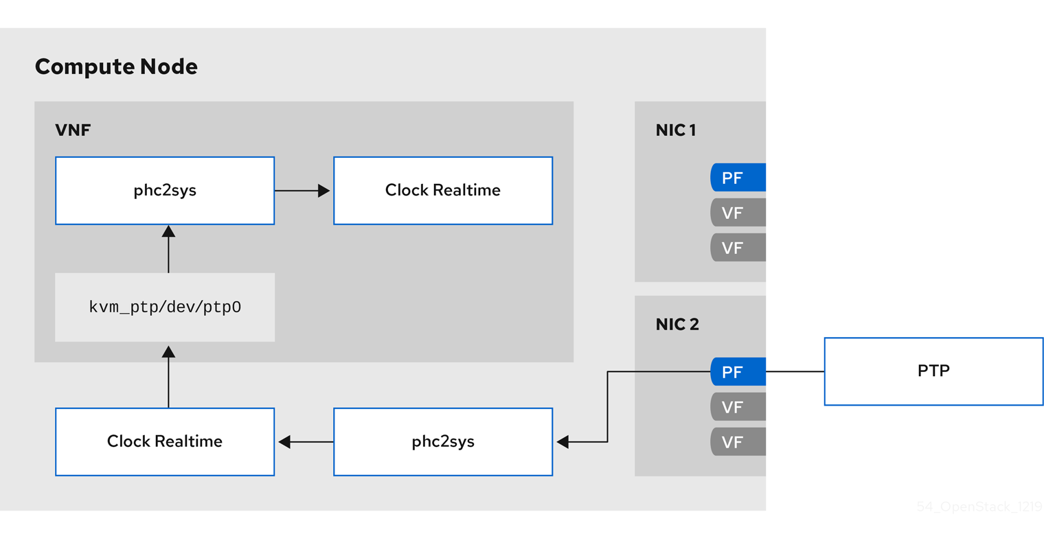
The following image is a overview of a packet journey in the Compute node in a PTP configuration.
Figure 11.2. PTP packet journey detail
11.9.1. Timemaster hardware requirements
Ensure that you have the following hardware functionality:
- You have configured the NICs with hardware timestamping capability.
- You have configured the switch to allow multicast packets.
- You have configured the switch to also function as a boundary or transparent clock.
You can verify the hardware timestamping with the command ethtool -T <device>.
$ ethtool -T p5p1
Time stamping parameters for p5p1:
Capabilities:
        hardware-transmit     (SOF_TIMESTAMPING_TX_HARDWARE)
        software-transmit     (SOF_TIMESTAMPING_TX_SOFTWARE)
        hardware-receive      (SOF_TIMESTAMPING_RX_HARDWARE)
        software-receive      (SOF_TIMESTAMPING_RX_SOFTWARE)
        software-system-clock (SOF_TIMESTAMPING_SOFTWARE)
        hardware-raw-clock    (SOF_TIMESTAMPING_RAW_HARDWARE)
PTP Hardware Clock: 6
Hardware Transmit Timestamp Modes:
        off                   (HWTSTAMP_TX_OFF)
        on                    (HWTSTAMP_TX_ON)
Hardware Receive Filter Modes:
        none                  (HWTSTAMP_FILTER_NONE)
        ptpv1-l4-sync         (HWTSTAMP_FILTER_PTP_V1_L4_SYNC)
        ptpv1-l4-delay-req    (HWTSTAMP_FILTER_PTP_V1_L4_DELAY_REQ)
        ptpv2-event           (HWTSTAMP_FILTER_PTP_V2_EVENT)
You can use either a transparent or boundary clock switch for better accuracy and less latency. You can use an uplink switch for the boundary clock. The boundary clock switch uses an 8-bit correctionField on the PTPv2 header to correct delay variations, and ensure greater accuracy on the end clock. In a transparent clock switch, the end clock calculates the delay variation, not the correctionField.
11.9.2. Configuring Timemaster
The default Red Hat OpenStack Platform (RHOSP) service for time synchronization in overcloud nodes is OS::TripleO::Services::Timesync.
Known limitations
- Enable NTP for virtualized controllers, and enable PTP for bare metal nodes.
-
Virtio interfaces are incompatible, because
ptp4lrequires a compatible PTP device. -
Use a physical function (PF) for a VM with SR-IOV. A virtual function (VF) does not expose the registers necessary for PTP, and a VM uses
kvm_ptpto calculate time. - High Availability (HA) interfaces with multiple sources and multiple network paths are incompatible.
Procedure
To enable the Timemaster service on the nodes that belong to a role that you choose, replace the line that contains
OS::TripleO::Services::Timesyncwith the lineOS::TripleO::Services::TimeMasterin theroles_data.yamlfile section for that role.#- OS::TripleO::Services::Timesync - OS::TripleO::Services::TimeMaster
Configure the heat parameters for the compute role that you use.
#Example
ComputeSriovParameters:
  PTPInterfaces: ‘0:eno1,1:eno2’
  PTPMessageTransport: ‘UDPv4’
Include the new environment file in the
openstack overcloud deploycommand with any other environment files that are relevant to your environment:$ openstack overcloud deploy \ --templates \ … -e <existing_overcloud_environment_files> \ -e <new_environment_file1> \ -e <new_environment_file2> \ …
- Replace <existing_overcloud_environment_files> with the list of environment files that are part of your existing deployment.
- Replace <new_environment_file> with the new environment file or files that you want to include in the overcloud deployment process.
Verification
Use the command
phc_ctl, installed withptp4linux, to query the NIC hardware clock.# phc_ctl <clock_name> get # phc_ctl <clock_name> cmp
11.9.3. Example timemaster configuration
$ cat /etc/timemaster.conf
# Configuration file for timemaster

#[ntp_server ntp-server.local]
#minpoll 4
#maxpoll 4

[ptp_domain 0]
interfaces eno1
#ptp4l_setting network_transport l2
#delay 10e-6

[timemaster]
ntp_program chronyd

[chrony.conf]
#include /etc/chrony.conf
server clock.redhat.com iburst minpoll 6 maxpoll 10

[ntp.conf]
includefile /etc/ntp.conf

[ptp4l.conf]
#includefile /etc/ptp4l.conf
network_transport L2

[chronyd]
path /usr/sbin/chronyd

[ntpd]
path /usr/sbin/ntpd
options -u ntp:ntp -g

[phc2sys]
path /usr/sbin/phc2sys
#options -w

[ptp4l]
path /usr/sbin/ptp4l
#options -2 -i eno1
11.9.4. Example timemaster operation
$ systemctl status timemaster
● timemaster.service - Synchronize system clock to NTP and PTP time sources
   Loaded: loaded (/usr/lib/systemd/system/timemaster.service; enabled; vendor preset: disabled)
   Active: active (running) since Tue 2020-08-25 19:10:18 UTC; 2min 6s ago
 Main PID: 2573 (timemaster)
    Tasks: 6 (limit: 357097)
   Memory: 5.1M
   CGroup: /system.slice/timemaster.service
           ├─2573 /usr/sbin/timemaster -f /etc/timemaster.conf
           ├─2577 /usr/sbin/chronyd -n -f /var/run/timemaster/chrony.conf
           ├─2582 /usr/sbin/ptp4l -l 5 -f /var/run/timemaster/ptp4l.0.conf -H -i eno1
           ├─2583 /usr/sbin/phc2sys -l 5 -a -r -R 1.00 -z /var/run/timemaster/ptp4l.0.socket -t [0:eno1] -n 0 -E ntpshm -M 0
           ├─2587 /usr/sbin/ptp4l -l 5 -f /var/run/timemaster/ptp4l.1.conf -H -i eno2
           └─2588 /usr/sbin/phc2sys -l 5 -a -r -R 1.00 -z /var/run/timemaster/ptp4l.1.socket -t [0:eno2] -n 0 -E ntpshm -M 1

Aug 25 19:11:53 computesriov-0 ptp4l[2587]: [152.562] [0:eno2] selected local clock e4434b.fffe.4a0c24 as best master