
Red Hat Training
A Red Hat training course is available for Red Hat OpenStack Platform
Chapter 2. OpenStack Networking Concepts
OpenStack Networking has system services to manage core services such as routing, DHCP, and metadata. Together, these services are included in the concept of the controller node, which is a conceptual role assigned to a physical server. A physical server is typically assigned the role of Network node, keeping it dedicated to the task of managing Layer 3 routing for network traffic to and from instances. In OpenStack Networking, you can have multiple physical hosts performing this role, allowing for redundant service in the event of hardware failure. For more information, see the chapter on Layer 3 High Availability.
Red Hat OpenStack Platform 11 added support for composable roles, allowing you to separate network services into a custom role. However, for simplicity, this guide assumes that a deployment uses the default controller role.
2.1. Installing OpenStack Networking (neutron)
2.1.1. Supported installation
The OpenStack Networking component is installed as part of a Red Hat OpenStack Platform director deployment. Refer to the Director Installation and Usage guide for more information.
2.2. OpenStack Networking diagram
This diagram depicts a sample OpenStack Networking deployment, with a dedicated OpenStack Networking node performing L3 routing and DHCP, and running the advanced services FWaaS and LBaaS. Two Compute nodes run the Open vSwitch (openvswitch-agent) and have two physical network cards each, one for tenant traffic, and another for management connectivity. The OpenStack Networking node has a third network card specifically for provider traffic:

2.3. Security Groups
Security groups and rules filter the type and direction of network traffic sent to (and received from) a given neutron port. This provides an additional layer of security to complement any firewall rules present on the Compute instance. The security group is a container object with one or more security rules. A single security group can manage traffic to multiple compute instances. Ports created for floating IP addresses, OpenStack Networking LBaaS VIPs, and instances are associated with a security group. If none is specified, then the port is associated with the default security group. By default, this group will drop all inbound traffic and allow all outbound traffic. Additional security rules can be added to the default security group to modify its behavior or new security groups can be created as necessary.
2.4. Open vSwitch
Open vSwitch (OVS) is a software-defined networking (SDN) virtual switch similar to the Linux software bridge. OVS provides switching services to virtualized networks with support for industry standard NetFlow, OpenFlow, and sFlow. Open vSwitch is also able to integrate with physical switches using layer 2 features, such as STP, LACP, and 802.1Q VLAN tagging. Tunneling with VXLAN and GRE is supported with Open vSwitch version 1.11.0-1.el6 or later.
Do not use LACP with OVS-based bonds, as this configuration is problematic and unsupported. Instead, consider using bond_mode=balance-slb as a replacement for this functionality. In addition, you can still use LACP with Linux bonding. For the technical details behind this requirement, see BZ#1267291.
To mitigate the risk of network loops in Open vSwitch, only a single interface or a single bond may be a member of a given bridge. If you require multiple bonds or interfaces, you can configure multiple bridges.
2.5. Modular Layer 2 (ML2)
ML2 is the OpenStack Networking core plug-in introduced in OpenStack’s Havana release. Superseding the previous model of monolithic plug-ins, ML2’s modular design enables the concurrent operation of mixed network technologies. The monolithic Open vSwitch and Linux Bridge plug-ins have been deprecated and removed; their functionality has instead been reimplemented as ML2 mechanism drivers.
ML2 is the default OpenStack Networking plug-in, with Open vSwitch configured as the default mechanism driver.
2.5.1. The reasoning behind ML2
Previously, OpenStack Networking deployments were only able to use the plug-in that had been selected at implementation time. For example, a deployment running the Open vSwitch plug-in was only able to use Open vSwitch exclusively; it wasn’t possible to simultaneously run another plug-in such as linuxbridge. This was found to be a limitation in environments with heterogeneous requirements.
2.5.2. ML2 network types
Multiple network segment types can be operated concurrently. In addition, these network segments can interconnect using ML2’s support for multi-segmented networks. Ports are automatically bound to the segment with connectivity; it is not necessary to bind them to a specific segment. Depending on the mechanism driver, ML2 supports the following network segment types:
- flat
- GRE
- local
- VLAN
- VXLAN
The various Type drivers are enabled in the ML2 section of the ml2_conf.ini file:
[ml2]
type_drivers = local,flat,vlan,gre,vxlan
2.5.3. ML2 Mechanism Drivers
Plug-ins have been reimplemented as mechanisms with a common code base. This approach enables code reuse and eliminates much of the complexity around code maintenance and testing.
Refer to the Release Notes for the list of supported mechanism drivers.
The various mechanism drivers are enabled in the ML2 section of the ml2_conf.ini file. For example:
[ml2]
mechanism_drivers = openvswitch,linuxbridge,l2population
If your deployment uses Red Hat OpenStack Platform director, then these settings are managed by director and should not be changed manually.
Neutron’s Linux Bridge ML2 driver and agent are being deprecated with Red Hat OpenStack Platform 11. The Open vSwitch (OVS) plugin is the one deployed by default by the OpenStack Platform director, and is recommended by Red Hat for general usage.
2.6. L2 Population
The L2 Population driver enables broadcast, multicast, and unicast traffic to scale out on large overlay networks. By default, Open vSwitch GRE and VXLAN replicate broadcasts to every agent, including those that do not host the destination network. This design requires the acceptance of significant network and processing overhead. The alternative design introduced by the L2 Population driver implements a partial mesh for ARP resolution and MAC learning traffic; it also creates tunnels for a particular network only between the nodes that host the network. This traffic is sent only to the necessary agent by encapsulating it as a targeted unicast.
1. Enable the L2 population driver by adding it to the list of mechanism drivers. You also need to have at least one tunneling driver enabled; either GRE, VXLAN, or both. Add the appropriate configuration options to the ml2_conf.ini file:
[ml2]
type_drivers = local,flat,vlan,gre,vxlan
mechanism_drivers = openvswitch,linuxbridge,l2population
Neutron’s Linux Bridge ML2 driver and agent are being deprecated with Red Hat OpenStack Platform 11. The Open vSwitch (OVS) plugin is the one deployed by default by the OpenStack Platform director, and is recommended by Red Hat for general usage.
2. Enable L2 population in the openvswitch_agent.ini file. This must be enabled on each node running the L2 agent:
[agent]
l2_population = True
To install ARP reply flows, you will need to configure the arp_responder flag. For example:
[agent]
l2_population = True
arp_responder = True
2.7. OpenStack Networking Services
By default, Red Hat OpenStack Platform includes components that integrate with the ML2 and Open vSwitch plugin to provide networking functionality in your deployment:
2.7.1. L3 Agent
The L3 agent is part of the openstack-neutron package. Network namespaces are used to provide each project with its own isolated layer 3 routers, which direct traffic and provide gateway services for the layer 2 networks; the L3 agent assists with managing these routers. The nodes on which the L3 agent is to be hosted must not have a manually-configured IP address on a network interface that is connected to an external network. Instead there must be a range of IP addresses from the external network that are available for use by OpenStack Networking. These IP addresses will be assigned to the routers that provide the link between the internal and external networks. The range selected must be large enough to provide a unique IP address for each router in the deployment as well as each desired floating IP.
2.7.2. DHCP Agent
The OpenStack Networking DHCP agent manages the network namespaces that are spawned for each project subnet to act as DHCP server. Each namespace is running a dnsmasq process that is capable of allocating IP addresses to virtual machines running on the network. If the agent is enabled and running when a subnet is created then by default that subnet has DHCP enabled.
2.7.3. Open vSwitch Agent
The Open vSwitch (OVS) neutron plug-in uses its own agent, which runs on each node and manages the OVS bridges. The ML2 plugin integrates with a dedicated agent to manage L2 networks. By default, Red Hat OpenStack Platform uses ovs-agent, which builds overlay networks using OVS bridges.
2.8. Tenant and Provider networks
The following diagram presents an overview of the tenant and provider network types, and illustrates how they interact within the overall OpenStack Networking topology:

2.8.1. Tenant networks
Tenant networks are created by users for connectivity within projects. They are fully isolated by default and are not shared with other projects. OpenStack Networking supports a range of tenant network types:
- Flat - All instances reside on the same network, which can also be shared with the hosts. No VLAN tagging or other network segregation takes place.
- VLAN - OpenStack Networking allows users to create multiple provider or tenant networks using VLAN IDs (802.1Q tagged) that correspond to VLANs present in the physical network. This allows instances to communicate with each other across the environment. They can also communicate with dedicated servers, firewalls, load balancers and other network infrastructure on the same layer 2 VLAN.
- VXLAN and GRE tunnels - VXLAN and GRE use network overlays to support private communication between instances. An OpenStack Networking router is required to enable traffic to traverse outside of the GRE or VXLAN tenant network. A router is also required to connect directly-connected tenant networks with external networks, including the Internet; the router provides the ability to connect to instances directly from an external network using floating IP addresses.
You can configure QoS policies for tenant networks. For more information, see Chapter 10, Configure Quality-of-Service (QoS).
2.8.2. Provider networks
Provider networks are created by the OpenStack administrator and map directly to an existing physical network in the data center. Useful network types in this category are flat (untagged) and VLAN (802.1Q tagged). It is possible to allow provider networks to be shared among tenants as part of the network creation process.
2.8.2.1. Flat provider networks
You can use flat provider networks to connect instances directly to the external network. This is useful if you have multiple physical networks (for example, physnet1 and physnet2) and separate physical interfaces (eth0 → physnet1 and eth1 → physnet2), and intend to connect each Compute and Network node to those external networks. If you would like to use multiple vlan-tagged interfaces on a single interface to connect to multiple provider networks, please refer to Section 7.2, “Using VLAN provider networks”.
2.8.2.2. Configure controller nodes
1. Edit /etc/neutron/plugin.ini (symbolic link to /etc/neutron/plugins/ml2/ml2_conf.ini) and add flat to the existing list of values, and set flat_networks to *. For example:
type_drivers = vxlan,flat
flat_networks =*
2. Create an external network as a flat network and associate it with the configured physical_network. Configuring it as a shared network (using --shared) will let other users create instances directly connected to it.
neutron net-create public01 --provider:network_type flat --provider:physical_network physnet1 --router:external=True --shared
3. Create a subnet using neutron subnet-create, or the dashboard. For example:
# neutron subnet-create --name public_subnet --enable_dhcp=False --allocation_pool start=192.168.100.20,end=192.168.100.100 --gateway=192.168.100.1 public01 192.168.100.0/24
4. Restart the neutron-server service to apply the change:
systemctl restart neutron-server
2.8.2.3. Configure the Network and Compute nodes
Perform these steps on the network node and compute nodes. This will connect the nodes to the external network, and allow instances to communicate directly with the external network.
1. Create an external network bridge (br-ex) and add an associated port (eth1) to it:
Create the external bridge in /etc/sysconfig/network-scripts/ifcfg-br-ex:
DEVICE=br-ex
TYPE=OVSBridge
DEVICETYPE=ovs
ONBOOT=yes
NM_CONTROLLED=no
BOOTPROTO=none
In /etc/sysconfig/network-scripts/ifcfg-eth1, configure eth1 to connect to br-ex:
DEVICE=eth1
TYPE=OVSPort
DEVICETYPE=ovs
OVS_BRIDGE=br-ex
ONBOOT=yes
NM_CONTROLLED=no
BOOTPROTO=none
Reboot the node or restart the network service for the changes to take effect.
2. Configure physical networks in /etc/neutron/plugins/ml2/openvswitch_agent.ini and map bridges to the physical network:
bridge_mappings = physnet1:br-ex
For more information on bridge mappings, see Chapter 11, Configure Bridge Mappings.
3. Restart the neutron-openvswitch-agent service on both the network and compute nodes for the changes to take effect:
systemctl restart neutron-openvswitch-agent
2.8.2.4. Configure the network node
1. Set external_network_bridge = to an empty value in /etc/neutron/l3_agent.ini:
Previously, OpenStack Networking used external_network_bridge when only a single bridge was used for connecting to an external network. This value may now be set to a blank string, which allows multiple external network bridges. OpenStack Networking will then create a patch from each bridge to br-int.
# Name of bridge used for external network traffic. This should be set to
# empty value for the linux bridge
external_network_bridge =
2. Restart neutron-l3-agent for the changes to take effect.
systemctl restart neutron-l3-agent
If there are multiple flat provider networks, then each of them should have a separate physical interface and bridge to connect them to the external network. You will need to configure the ifcfg-* scripts appropriately and use a comma-separated list for each network when specifying the mappings in the bridge_mappings option. For more information on bridge mappings, see Chapter 11, Configure Bridge Mappings.
2.9. Layer 2 and layer 3 networking
When designing your virtual network, you will need to anticipate where the majority of traffic is going to be sent. Network traffic moves faster within the same logical network, rather than between networks. This is because traffic between logical networks (using different subnets) needs to pass through a router, resulting in additional latency.
Consider the diagram below which has network traffic flowing between instances on separate VLANs:
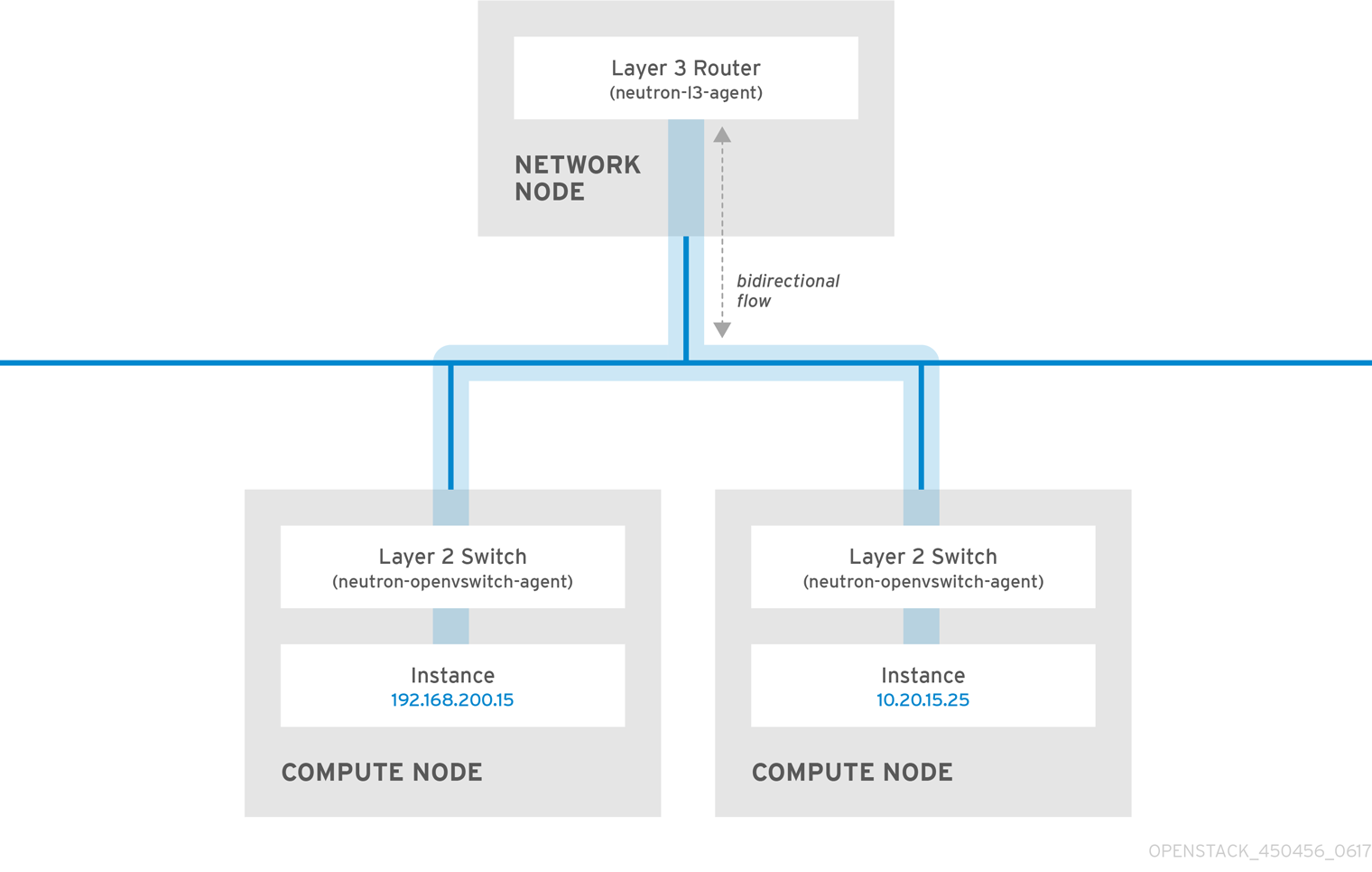
Even a high performance hardware router is still going to add some latency to this configuration.
2.9.1. Use switching where possible
Switching occurs at a lower level of the network (layer 2), so can function much quicker than the routing that occurs at layer 3. The preference should be to have as few hops as possible between systems that frequently communicate. For example, this diagram depicts a switched network that spans two physical nodes, allowing the two instances to directly communicate without using a router for navigation first. You’ll notice that the instances now share the same subnet, to indicate that they’re on the same logical network:
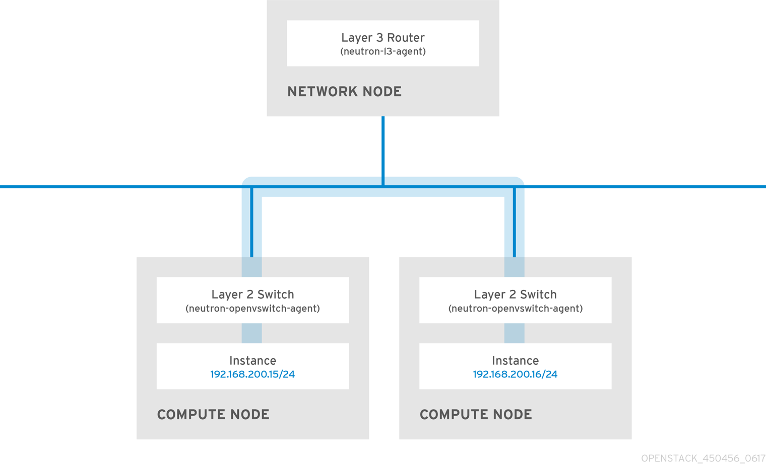
In order to allow instances on separate nodes to communicate as if they’re on the same logical network, you’ll need to use an encapsulation tunnel such as VXLAN or GRE. It is recommended you consider adjusting the MTU size from end-to-end in order to accommodate the additional bits required for the tunnel header, otherwise network performance can be negatively impacted as a result of fragmentation. For more information, see Configure MTU Settings.
You can further improve the performance of VXLAN tunneling by using supported hardware that features VXLAN offload capabilities. The full list is available here: https://access.redhat.com/articles/1390483