
40.5. Network Partition Recovery Examples
- A distributed four node cluster with
ownersset to 3 at Section 40.5.1, “Distributed 4-Node Cache Example With 3 Owners” - A distributed four node cluster with
ownersset to 2 at Section 40.5.2, “Distributed 4-Node Cache Example With 2 Owners” - A distributed five node cluster with
ownersset to 3 at Section 40.5.3, “Distributed 5-Node Cache Example With 3 Owners” - A replicated four node cluster with
ownersset to 4 at Section 40.5.4, “Replicated 4-Node Cache Example With 4 Owners” - A replicated five node cluster with
ownersset to 5 at Section 40.5.5, “Replicated 5-Node Cache Example With 5 Owners” - A replicated eight node cluster with
ownersset to 8 at Section 40.5.6, “Replicated 8-Node Cache Example With 8 Owners”
40.5.1. Distributed 4-Node Cache Example With 3 Owners
k1, k2, k3, and k4). For this cache, owners equals 3, which means that each data entry must have three copies on various nodes in the cache.
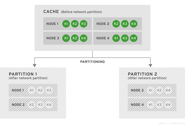
Figure 40.1. Cache Before and After a Network Partition
owners) nodes left from the last stable view. As a result, none of the four entries (k1, k2, k3, and k4) are available for reads or writes. No new entries can be written in either degraded partition, as neither partition can store 3 copies of an entry.
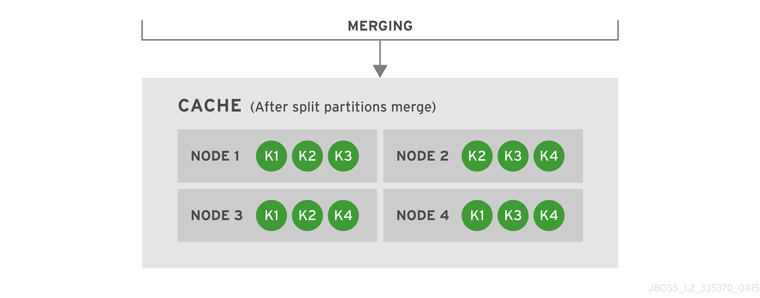
Figure 40.2. Cache After Partitions Are Merged
k1, k2, k3, and k4).
40.5.2. Distributed 4-Node Cache Example With 2 Owners
owners equals 2, so the four data entries (k1, k2, k3 and k4) have two copies each in the cache.
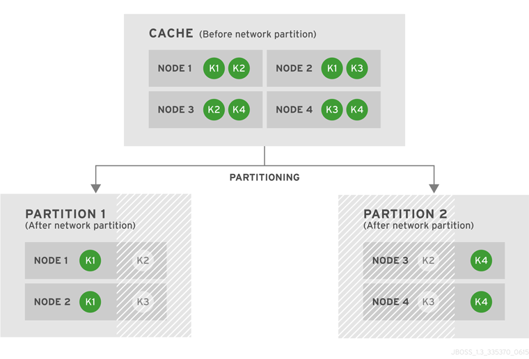
Figure 40.3. Cache Before and After a Network Partition
k1 is available for reads and writes because owners equals 2 and both copies of the entry remain in Partition 1. In Partition 2, k4 is available for reads and writes for the same reason. The entries k2 and k3 become unavailable in both partitions, as neither partition contains all copies of these entries. A new entry k5 can be written to a partition only if that partition were to own both copies of k5.
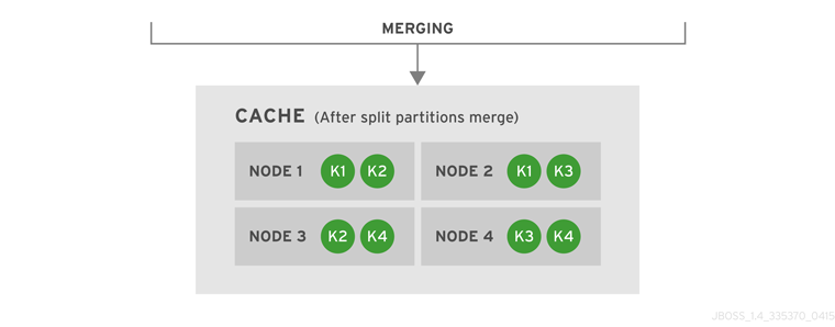
Figure 40.4. Cache After Partitions Are Merged
k1, k2, k3 and k4).
40.5.3. Distributed 5-Node Cache Example With 3 Owners
owners equal to 3.
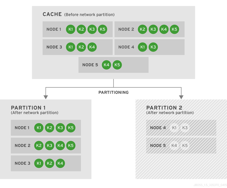
Figure 40.5. Cache Before and After a Network Partition
owners nodes.
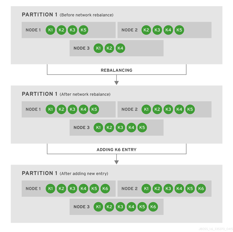
Figure 40.6. Partition 1 Rebalances and Another Entry is Added
owners equals 3) in the cache. As a result, each of the three nodes contains a copy of every entry in the cache. Next, we add a new entry, k6, to the cache. Since the owners value is still 3, and there are three nodes in Partition 1, each node includes a copy of k6.
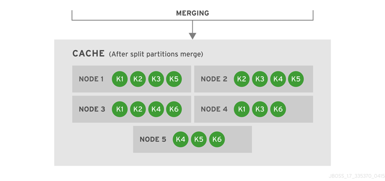
Figure 40.7. Cache After Partitions Are Merged
owners=3), JBoss Data Grid rebalances the nodes so that the data entries are distributed between the four nodes in the cache. The new combined cache becomes fully available.
40.5.4. Replicated 4-Node Cache Example With 4 Owners
owners equal to 4.
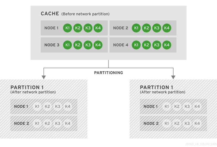
Figure 40.8. Cache Before and After a Network Partition
k1, k2, k3, and k4 are unavailable for reads and writes because neither of the two partitions owns all copies of any of the four keys.
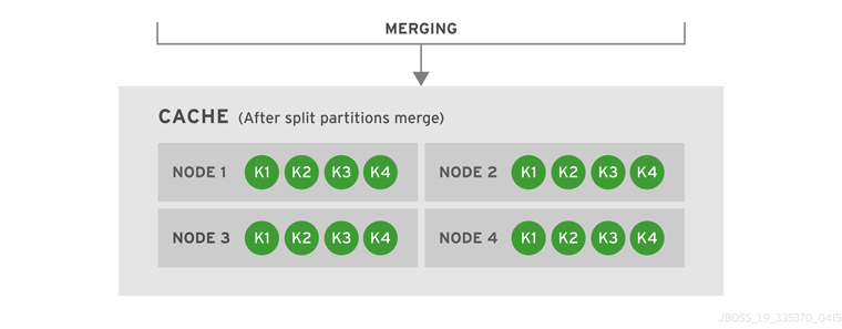
Figure 40.9. Cache After Partitions Are Merged
k1, k2, k3, and k4).
40.5.5. Replicated 5-Node Cache Example With 5 Owners
owners equal to 5.

Figure 40.10. Cache Before and After a Network Partition
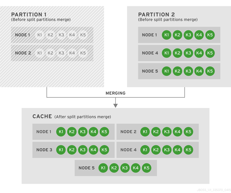
Figure 40.11. Both Partitions Are Merged Into One Cache
40.5.6. Replicated 8-Node Cache Example With 8 Owners
owners equal to 8.
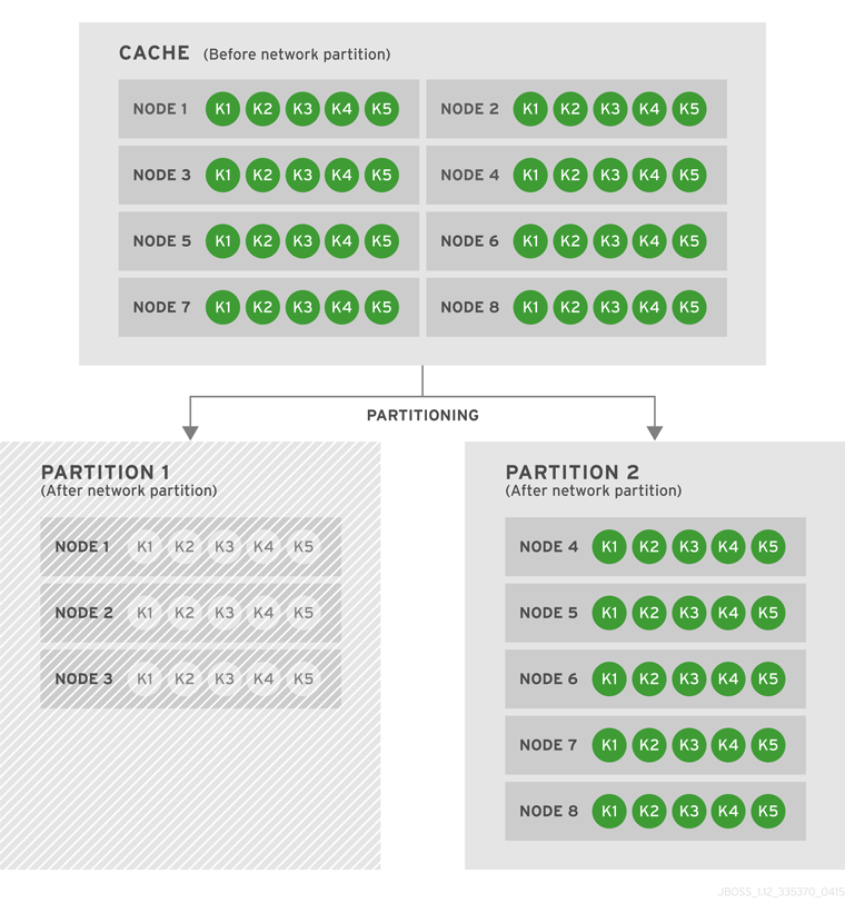
Figure 40.12. Cache Before and After a Network Partition
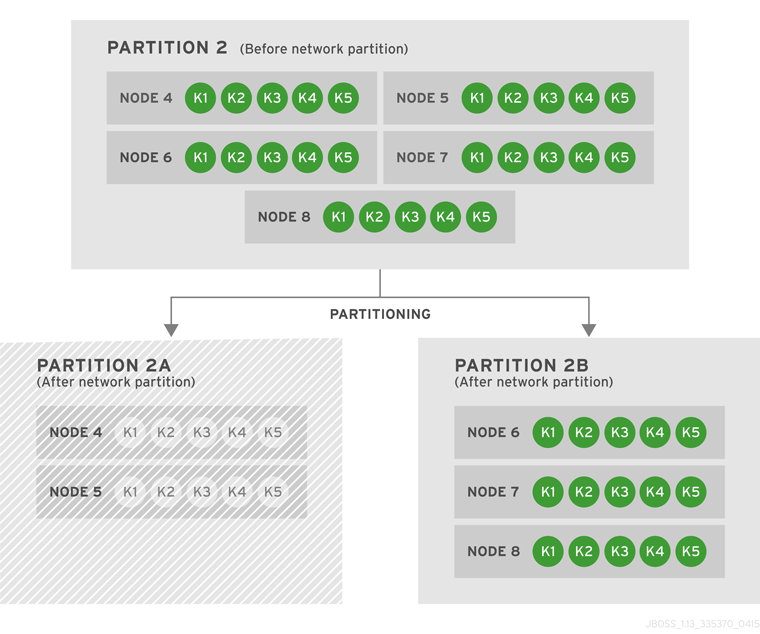
Figure 40.13. Partition 2 Further Splits into Partitions 2A and 2B
There are four potential resolutions for the caches from this scenario:
- Case 1: Partitions 2A and 2B Merge
- Case 2: Partition 1 and 2A Merge
- Case 3: Partition 1 and 2B Merge
- Case 4: Partition 1, Partition 2A, and Partition 2B Merge Together
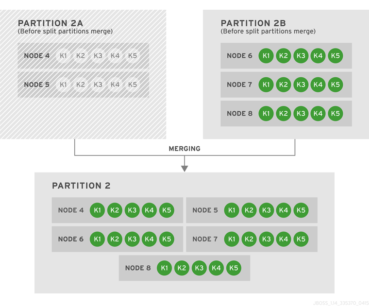
Figure 40.14. Case 1: Partitions 2A and 2B Merge
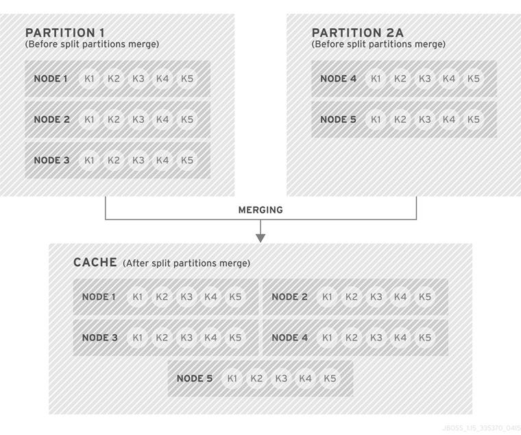
Figure 40.15. Case 2: Partition 1 and 2A Merge
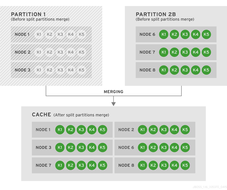
Figure 40.16. Case 3: Partition 1 and 2B Merge
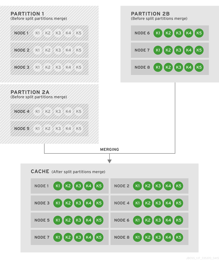
Figure 40.17. Case 4: Partition 1, Partition 2A, and Partition 2B Merge Together