
Spine Leaf Networking
Configuring routed spine-leaf networks using Red Hat OpenStack Platform director
Abstract
Making open source more inclusive
Red Hat is committed to replacing problematic language in our code, documentation, and web properties. We are beginning with these four terms: master, slave, blacklist, and whitelist. Because of the enormity of this endeavor, these changes will be implemented gradually over several upcoming releases. For more details, see our CTO Chris Wright’s message.
Chapter 1. Introduction to spine-leaf networking
The following chapters provide information about constructing a spine-leaf network topology for your Red Hat OpenStack Platform environment. This includes a full end-to-end scenario and example files to help replicate a more extensive network topology within your own environment.
1.1. Spine-leaf networking
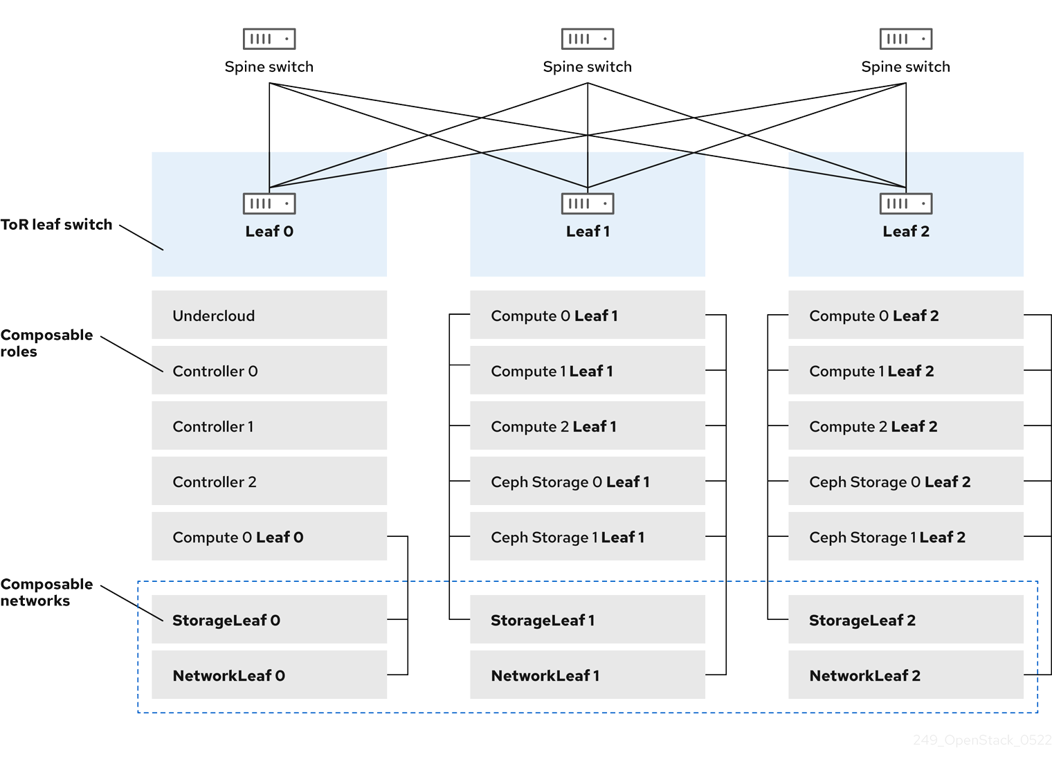
Red Hat OpenStack Platform has a composable network architecture that you can use to adapt your networking to the routed spine-leaf data center topology. In a practical application of routed spine-leaf, a leaf is represented as a composable Compute or Storage role usually in a data center rack, as shown in Figure 1.1, "Routed spine-leaf example". The Leaf 0 rack has an undercloud node, Controller nodes, and Compute nodes. The composable networks are presented to the nodes, which have been assigned to composable roles. The following diagram contains the following configuration:
-
The
StorageLeafnetworks are presented to the Ceph storage and Compute nodes. -
The
NetworkLeafrepresents an example of any network you might want to compose.
Figure 1.1. Routed spine-leaf example
1.2. Spine-leaf network topology
The spine-leaf scenario takes advantage of OpenStack Networking (neutron) functionality to define multiple subnets within segments of a single network. Each network uses a base network which acts as Leaf 0. Director creates Leaf 1 and Leaf 2 subnets as segments of the main network.
This scenario uses the following networks:
Table 1.1. Leaf 0 Networks (base networks)
| Network | Roles attached | Subnet |
|---|---|---|
| Provisioning / Ctlplane / Leaf0 | Controller, ComputeLeaf0, CephStorageLeaf0 | 192.168.10.0/24 |
| Storage | Controller, ComputeLeaf0, CephStorageLeaf0 | 172.16.0.0/24 |
| StorageMgmt | Controller, CephStorageLeaf0 | 172.17.0.0/24 |
| InternalApi | Controller, ComputeLeaf0 | 172.18.0.0/24 |
| Tenant [1] | Controller, ComputeLeaf0 | 172.19.0.0/24 |
| External | Controller | 10.1.1.0/24 |
[1] Tenant networks are also known as project networks.
Table 1.2. Leaf 1 Networks
| Network | Roles attached | Subnet |
|---|---|---|
| Provisioning / Ctlplane / Leaf1 | ComputeLeaf1, CephStorageLeaf1 | 192.168.11.0/24 |
| StorageLeaf1 | ComputeLeaf1, CephStorageLeaf1 | 172.16.1.0/24 |
| StorageMgmtLeaf1 | CephStorageLeaf1 | 172.17.1.0/24 |
| InternalApiLeaf1 | ComputeLeaf1 | 172.18.1.0/24 |
| TenantLeaf1 [1] | ComputeLeaf1 | 172.19.1.0/24 |
[1] Tenant networks are also known as project networks.
Table 1.3. Leaf 2 Networks
| Network | Roles attached | Subnet |
|---|---|---|
| Provisioning / Ctlplane / Leaf2 | ComputeLeaf2, CephStorageLeaf2 | 192.168.12.0/24 |
| StorageLeaf2 | ComputeLeaf2, CephStorageLeaf2 | 172.16.2.0/24 |
| StorageMgmtLeaf2 | CephStorageLeaf2 | 172.17.2.0/24 |
| InternalApiLeaf2 | ComputeLeaf2 | 172.18.2.0/24 |
| TenantLeaf2 [1] | ComputeLeaf2 | 172.19.2.0/24 |
[1] Tenant networks are also known as project networks.
Figure 1.2. Spine-leaf network topology

1.3. Spine-leaf requirements
To deploy the overcloud on a network with a L3 routed architecture, complete the following prerequisite steps:
- Layer-3 routing
- Configure the routing of the network infrastructure to enable traffic between the different L2 segments. You can configure this routing statically or dynamically.
- DHCP-Relay
-
Each L2 segment not local to the undercloud must provide
dhcp-relay. You must forward DHCP requests to the undercloud on the provisioning network segment where the undercloud is connected.
The undercloud uses two DHCP servers. One for baremetal node introspection, and another for deploying overcloud nodes. Ensure that you read DHCP relay configuration to understand the requirements when you configure dhcp-relay.
1.4. Spine-leaf limitations
- Some roles, such as the Controller role, use virtual IP addresses and clustering. The mechanism behind this functionality requires L2 network connectivity between these nodes. You must place these nodes within the same leaf.
- Similar restrictions apply to Networker nodes. The network service implements highly-available default paths in the network with Virtual Router Redundancy Protocol (VRRP). Because VRRP uses a virtual router IP address, you must connect master and backup nodes to the same L2 network segment.
- When you use tenant or provider networks with VLAN segmentation, you must share the particular VLANs between all Networker and Compute nodes.
It is possible to configure the network service with multiple sets of Networker nodes. Each set of Networker nodes share routes for their networks, and VRRP provides highly-available default paths within each set of Networker nodes. In this type of configuration, all Networker nodes that share networks must be on the same L2 network segment.
Chapter 2. Configuring routed spine-leaf in the undercloud
This section describes a use case about how to configure the undercloud to accommodate routed spine-leaf with composable networks.
2.1. Configuring the spine leaf provisioning networks
To configure the provisioning networks for your spine leaf infrastructure, edit the undercloud.conf file and set the relevant parameters included in the following procedure.
Procedure
-
Log in to the undercloud as the
stackuser. If you do not already have an
undercloud.conffile, copy the sample template file:[stack@director ~]$ cp /usr/share/python-tripleoclient/undercloud.conf.sample ~/undercloud.conf
-
Edit the
undercloud.conffile. Set the following values in the
[DEFAULT]section:Set
local_ipto the undercloud IP onleaf0:local_ip = 192.168.10.1/24
Set
undercloud_public_hostto the externally facing IP address of the undercloud:undercloud_public_host = 10.1.1.1
Set
undercloud_admin_hostto the administration IP address of the undercloud. This IP address is usually on leaf0:undercloud_admin_host = 192.168.10.2
Set
local_interfaceto the interface to bridge for the local network:local_interface = eth1
Set
enable_routed_networkstotrue:enable_routed_networks = true
Define your list of subnets using the
subnetsparameter. Define one subnet for each L2 segment in the routed spine and leaf:subnets = leaf0,leaf1,leaf2
Specify the subnet associated with the physical L2 segment local to the undercloud using the
local_subnetparameter:local_subnet = leaf0
Set the value of
undercloud_nameservers.undercloud_nameservers = 10.11.5.19,10.11.5.20
TipYou can find the current IP addresses of the DNS servers that are used for the undercloud nameserver by looking in /etc/resolv.conf.
Create a new section for each subnet that you define in the
subnetsparameter:[leaf0] cidr = 192.168.10.0/24 dhcp_start = 192.168.10.10 dhcp_end = 192.168.10.90 inspection_iprange = 192.168.10.100,192.168.10.190 gateway = 192.168.10.1 masquerade = False [leaf1] cidr = 192.168.11.0/24 dhcp_start = 192.168.11.10 dhcp_end = 192.168.11.90 inspection_iprange = 192.168.11.100,192.168.11.190 gateway = 192.168.11.1 masquerade = False [leaf2] cidr = 192.168.12.0/24 dhcp_start = 192.168.12.10 dhcp_end = 192.168.12.90 inspection_iprange = 192.168.12.100,192.168.12.190 gateway = 192.168.12.1 masquerade = False
-
Save the
undercloud.conffile. Run the undercloud installation command:
[stack@director ~]$ openstack undercloud install
This configuration creates three subnets on the provisioning network or control plane. The overcloud uses each network to provision systems within each respective leaf.
To ensure proper relay of DHCP requests to the undercloud, you might need to configure a DHCP relay.
2.2. Configuring a DHCP relay
You run the DHCP relay service on a switch, router, or server that is connected to the remote network segment you want to forward the requests from.
Do not run the DHCP relay service on the undercloud.
The undercloud uses two DHCP servers on the provisioning network:
- An introspection DHCP server.
- A provisioning DHCP server.
You must configure the DHCP relay to forward DHCP requests to both DHCP servers on the undercloud.
You can use UDP broadcast with devices that support it to relay DHCP requests to the L2 network segment where the undercloud provisioning network is connected. Alternatively, you can use UDP unicast, which relays DHCP requests to specific IP addresses.
Configuration of DHCP relay on specific device types is beyond the scope of this document. As a reference, this document provides a DHCP relay configuration example using the implementation in ISC DHCP software. For more information, see manual page dhcrelay(8).
DHCP option 79 is required for some relays, particularly relays that serve DHCPv6 addresses, and relays that do not pass on the originating MAC address. For more information, see RFC6939.
Broadcast DHCP relay
This method relays DHCP requests using UDP broadcast traffic onto the L2 network segment where the DHCP server or servers reside. All devices on the network segment receive the broadcast traffic. When using UDP broadcast, both DHCP servers on the undercloud receive the relayed DHCP request. Depending on the implementation, you can configure this by specifying either the interface or IP network address:
- Interface
- Specify an interface that is connected to the L2 network segment where the DHCP requests are relayed.
- IP network address
- Specify the network address of the IP network where the DHCP requests are relayed.
Unicast DHCP relay
This method relays DHCP requests using UDP unicast traffic to specific DHCP servers. When you use UDP unicast, you must configure the device that provides the DHCP relay to relay DHCP requests to both the IP address that is assigned to the interface used for introspection on the undercloud and the IP address of the network namespace that the OpenStack Networking (neutron) service creates to host the DHCP service for the ctlplane network.
The interface used for introspection is the one defined as inspection_interface in the undercloud.conf file. If you have not set this parameter, the default interface for the undercloud is br-ctlplane.
It is common to use the br-ctlplane interface for introspection. The IP address that you define as the local_ip in the undercloud.conf file is on the br-ctlplane interface.
The IP address allocated to the Neutron DHCP namespace is the first address available in the IP range that you configure for the local_subnet in the undercloud.conf file. The first address in the IP range is the one that you define as dhcp_start in the configuration. For example, 192.168.10.10 is the IP address if you use the following configuration:
[DEFAULT]
local_subnet = leaf0
subnets = leaf0,leaf1,leaf2

[leaf0]
cidr = 192.168.10.0/24
dhcp_start = 192.168.10.10
dhcp_end = 192.168.10.90
inspection_iprange = 192.168.10.100,192.168.10.190
gateway = 192.168.10.1
masquerade = False
The IP address for the DHCP namespace is automatically allocated. In most cases, this address is the first address in the IP range. To verify that this is the case, run the following commands on the undercloud:
$ openstack port list --device-owner network:dhcp -c "Fixed IP Addresses"
+----------------------------------------------------------------------------+
| Fixed IP Addresses                                                         |
+----------------------------------------------------------------------------+
| ip_address='192.168.10.10', subnet_id='7526fbe3-f52a-4b39-a828-ec59f4ed12b2' |
+----------------------------------------------------------------------------+
$ openstack subnet show 7526fbe3-f52a-4b39-a828-ec59f4ed12b2 -c name
+-------+--------+
| Field | Value  |
+-------+--------+
| name  | leaf0  |
+-------+--------+
Example dhcrelay configuration
In the following examples, the dhcrelay command in the dhcp package uses the following configuration:
-
Interfaces to relay incoming DHCP request:
eth1,eth2, andeth3. -
Interface the undercloud DHCP servers on the network segment are connected to:
eth0. -
The DHCP server used for introspection is listening on IP address:
192.168.10.1. -
The DHCP server used for provisioning is listening on IP address
192.168.10.10.
This results in the following dhcrelay command:
dhcrelayversion 4.2.x:$ sudo dhcrelay -d --no-pid 192.168.10.10 192.168.10.1 \ -i eth0 -i eth1 -i eth2 -i eth3
dhcrelayversion 4.3.x and later:$ sudo dhcrelay -d --no-pid 192.168.10.10 192.168.10.1 \ -iu eth0 -id eth1 -id eth2 -id eth3
Example Cisco IOS routing switch configuration
This example uses the following Cisco IOS configuration to perform the following tasks:
- Configure a VLAN to use for the provisioning network.
- Add the IP address of the leaf.
-
Forward UDP and BOOTP requests to the introspection DHCP server that listens on IP address:
192.168.10.1. -
Forward UDP and BOOTP requests to the provisioning DHCP server that listens on IP address
192.168.10.10.
interface vlan 2
ip address 192.168.24.254 255.255.255.0
ip helper-address 192.168.10.1
ip helper-address 192.168.10.10
!
Now that you have configured the provisioning network, you can configure the remaining overcloud leaf networks.
2.3. Designating a role for leaf nodes
Each role in each leaf network requires a flavor and role assignment so that you can tag nodes into their respective leaf. Complete the following steps to create and assign each flavor to a role.
Procedure
Source the
stackrcfile:[stack@director ~]$ source ~/stackrc
Retrieve a list of your nodes to identify their UUIDs:
(undercloud)$ openstack baremetal node list
Assign each bare metal node that you want to designate for a role with a custom resource class that identifies its leaf network and role.
openstack baremetal node set \
 --resource-class baremetal.<ROLE> <node>
- Replace <ROLE> with a name that identifies the role.
Replace <node> with the ID of the bare metal node.
For example, enter the following command to tag a node with UUID 58c3d07e-24f2-48a7-bbb6-6843f0e8ee13 to the Compute role on Leaf2:
(undercloud)$ openstack baremetal node set \
 --resource-class baremetal.COMPUTE-LEAF2 58c3d07e-24f2-48a7-bbb6-6843f0e8ee13
-
Add each role to your
overcloud-baremetal-deploy.yamlif it is not already defined. Define the resource class that you want to assign to the nodes for the role:
- name: <role> count: 1 defaults: resource_class: baremetal.<ROLE>- Replace <role> with the name of the role.
- Replace <ROLE> with a name that identifies the role.
In a baremetal-deploy.yaml file, define the resource class that you want to assign to the nodes for the role. Specify the role, profile, quantity, and associated networks that you are deploying:
- name: <role> count: 1 hostname_format: <role>-%index% ansible_playbooks: - playbook: bm-deploy-playbook.yaml defaults: resource_class: baremetal.<ROLE> profile: control networks: - network: external subnet: external_subnet - network: internal_api subnet: internal_api_subnet01 - network: storage subnet: storage_subnet01 - network: storage_mgmt subnet: storage_mgmt_subnet01 - network: tenant subnet: tenant_subnet01 network_config: template: templates/multiple_nics/multiple_nics_dvr.j2 default_route_network: - external- Replace <role> with the name of the role.
Replace <ROLE> with a name that identifies the role.
NoteYou must create a
baremetal-deploy.yamlenvironment file for every stack you are deploying, in/home/stack/<stack>.
2.4. Mapping bare metal node ports to control plane network segments
To enable deployment on a L3 routed network, you must configure the physical_network field on the bare metal ports. Each bare metal port is associated with a bare metal node in the OpenStack Bare Metal (ironic) service. The physical network names are the names that you include in the subnets option in the undercloud configuration.
The physical network name of the subnet specified as local_subnet in the undercloud.conf file is always named ctlplane.
Procedure
Source the
stackrcfile:$ source ~/stackrc
Check the bare metal nodes:
$ openstack baremetal node list
Ensure that the bare metal nodes are either in
enrollormanageablestate. If the bare metal node is not in one of these states, the command that sets thephysical_networkproperty on the baremetal port fails. To set all nodes tomanageablestate, run the following command:$ for node in $(openstack baremetal node list -f value -c Name); do openstack baremetal node manage $node --wait; done
Check which baremetal ports are associated with which baremetal node:
$ openstack baremetal port list --node <node-uuid>
Set the
physical-networkparameter for the ports. In the example below, three subnets are defined in the configuration:leaf0,leaf1, andleaf2. The local_subnet isleaf0. Because the physical network for thelocal_subnetis alwaysctlplane, the baremetal port connected toleaf0uses ctlplane. The remaining ports use the other leaf names:$ openstack baremetal port set --physical-network ctlplane <port-uuid> $ openstack baremetal port set --physical-network leaf1 <port-uuid> $ openstack baremetal port set --physical-network leaf2 <port-uuid>
Introspect the nodes before you deploy the overcloud. Include the
--all-manageableand--provideoptions to set the nodes as available for deployment:$ openstack overcloud node introspect --all-manageable --provide
2.5. Adding a new leaf to a spine-leaf provisioning network
When increasing network capacity which can include adding new physical sites, you might need to add a new leaf and a corresponding subnet to your Red Hat OpenStack Platform spine-leaf provisioning network. When provisioning a leaf on the overcloud, the corresponding undercloud leaf is used.
Prerequisites
- Your RHOSP deployment uses a spine-leaf network topology.
Procedure
- Log in to the undercloud host as the stack user.
Source the undercloud credentials file:
$ source ~/stackrc
In the
/home/stack/undercloud.conffile, do the following:Locate the
subnetsparameter, and add a new subnet for the leaf that you are adding.A subnet represents an L2 segment in the routed spine and leaf:
Example
In this example, a new subnet (
leaf3) is added for the new leaf (leaf3):subnets = leaf0,leaf1,leaf2,leaf3
Create a section for the subnet that you added.
Example
In this example, the section
[leaf3]is added for the new subnet (leaf3):[leaf0] cidr = 192.168.10.0/24 dhcp_start = 192.168.10.10 dhcp_end = 192.168.10.90 inspection_iprange = 192.168.10.100,192.168.10.190 gateway = 192.168.10.1 masquerade = False [leaf1] cidr = 192.168.11.0/24 dhcp_start = 192.168.11.10 dhcp_end = 192.168.11.90 inspection_iprange = 192.168.11.100,192.168.11.190 gateway = 192.168.11.1 masquerade = False [leaf2] cidr = 192.168.12.0/24 dhcp_start = 192.168.12.10 dhcp_end = 192.168.12.90 inspection_iprange = 192.168.12.100,192.168.12.190 gateway = 192.168.12.1 masquerade = False [leaf3] cidr = 192.168.13.0/24 dhcp_start = 192.168.13.10 dhcp_end = 192.168.13.90 inspection_iprange = 192.168.13.100,192.168.13.190 gateway = 192.168.13.1 masquerade = False
-
Save the
undercloud.conffile. Reinstall your undercloud:
$ openstack undercloud install
Additional resources
Chapter 3. Alternative provisioning network methods
This section contains information about other methods that you can use to configure the provisioning network to accommodate routed spine-leaf with composable networks.
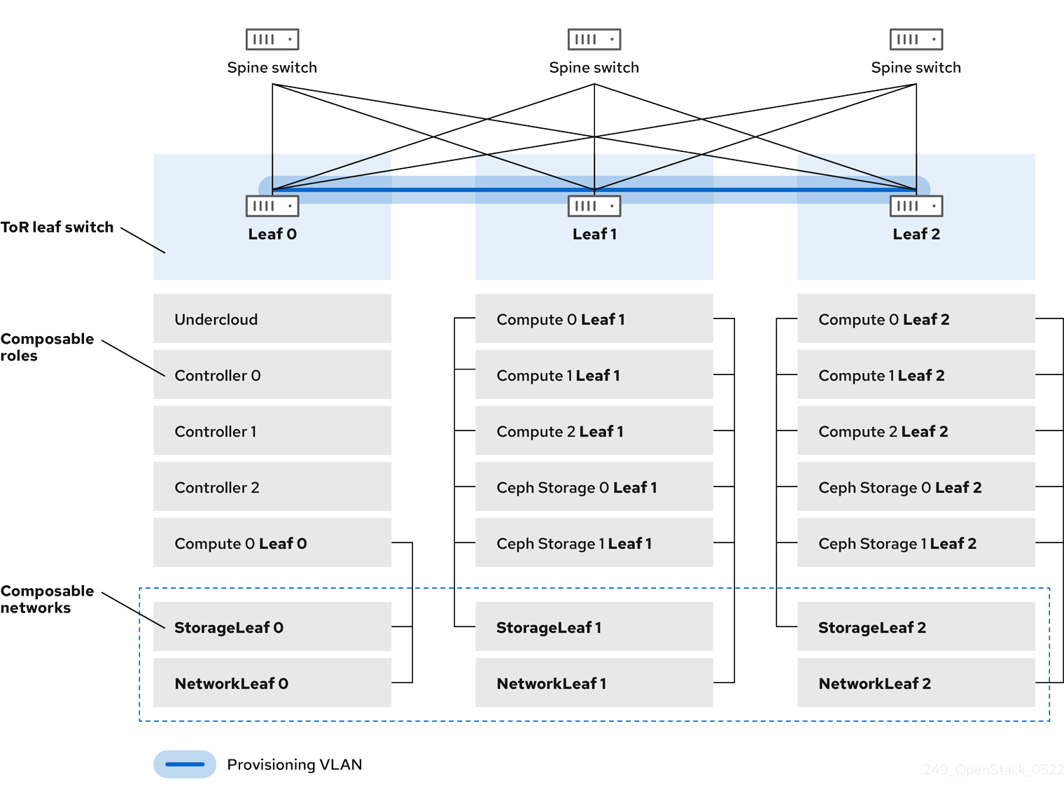
3.1. VLAN Provisioning network
In this example, the director deploys new overcloud nodes through the provisioning network and uses a VLAN tunnel across the L3 topology. For more information, see Figure 3.1, "VLAN provisioning network topology". If you use a VLAN provisioning network, the director DHCP servers can send DHCPOFFER broadcasts to any leaf. To establish this tunnel, trunk a VLAN between the Top-of-Rack (ToR) leaf switches. In the following diagram, the StorageLeaf networks are presented to the Ceph storage and Compute nodes; the NetworkLeaf represents an example of any network that you want to compose.
Figure 3.1. VLAN provisioning network topology
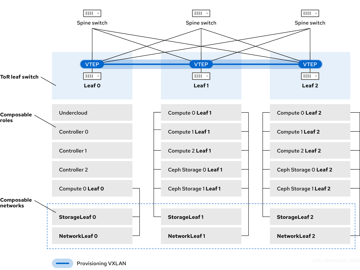
3.2. VXLAN Provisioning network
In this example, the director deploys new overcloud nodes through the provisioning network and uses a VXLAN tunnel to span across the layer 3 topology. For more information, see Figure 3.2, "VXLAN provisioning network topology". If you use a VXLAN provisioning network, the director DHCP servers can send DHCPOFFER broadcasts to any leaf. To establish this tunnel, configure VXLAN endpoints on the Top-of-Rack (ToR) leaf switches.
Figure 3.2. VXLAN provisioning network topology
Chapter 4. Configuring the overcloud
Use Red Hat OpenStack Platform (RHOSP) director to install and configure spine leaf networking in the RHOSP overcloud. The high-level steps are:
- Define the overcloud networks for each leaf.
- Create a composable role for each leaf and attach the composable network to each respective role.
- Create a unique NIC configuration for each role.
- Set the control plane parameters and the change bridge mappings so that each leaf routes traffic through the specific bridge or VLAN on that leaf.
- Define virtual IPs (VIPs) for your overcloud endpoints, and identify the subnet for each VIP.
- Provision your overcloud networks and overcloud VIPs.
Register the bare metal nodes in your overcloud.
NoteSkip steps 7, 8, and 9 if you are using pre-provisioned bare metal nodes.
- Introspect the bare metal nodes in your overcloud.
- Provision bare metal nodes.
- Deploy your overcloud using the configuration you set in the earlier steps.
4.1. Defining the leaf networks
The Red Hat OpenStack Platform (RHOSP) director creates the overcloud leaf networks from a YAML-formatted, custom network definition file that you construct. This custom network definition file lists each composable network and its attributes and also defines the subnets needed for each leaf.
Complete the following steps to create a YAML-formatted, custom network definition file that contains the specifications for your spine-leaf network on the overcloud. Later, the provisioning process creates a heat environment file from your network definition file that you will include when you deploy your RHOSP overcloud.
Prerequisites
-
Access to the undercloud host and credentials for the
stackuser.
Procedure
-
Log in to the undercloud host as the
stackuser. Source the
stackrcundercloud credential file:$ source ~/stackrc
Create a
templatesdirectory under/home/stack:$ mkdir /home/stack/templates
Use the default template,
routed-networks.yaml, template as a basis to create a custom network definition template for your environment, by copying it to yourtemplatesdirectory:Example
$ cp /usr/share/openstack-tripleo-heat-templates/network-data-samples/\
routed-networks.yaml \
/home/stack/templates/spine-leaf-networks-data.yaml
Edit your copy of the network definition template to define each base network and respective leaf subnets as a composable network item.
TipFor information, see Network definition file configuration options in the Director Installation and Usage guide.
Example
The following example demonstrates how to define the Internal API network and its leaf networks:
- name: InternalApi
  name_lower: internal_api
  vip: true
  mtu: 1500
  subnets:
    internal_api_subnet:
      ip_subnet: 172.16.32.0/24
      gateway_ip: 172.16.32.1
      allocation_pools:
        - start: 172.16.32.4
          end: 172.16.32.250
      vlan: 20
    internal_api_leaf1_subnet:
      ip_subnet: 172.16.33.0/24
      gateway_ip: 172.16.33.1
      allocation_pools:
        - start: 172.16.33.4
          end: 172.16.33.250
      vlan: 30
    internal_api_leaf2_subnet:
      ip_subnet: 172.16.34.0/24
      gateway_ip: 172.16.34.1
      allocation_pools:
        - start: 172.16.34.4
          end: 172.16.34.250
      vlan: 40
You do not define the Control Plane networks in your custom network definition template because the undercloud has already created these networks. However, you must set the parameters manually so that the overcloud can configure the NICs accordingly. For more information, see Configuring routed spine-leaf in the undercloud.
There is currently no automatic validation for the network subnet and allocation_pools values. Ensure that you define these values consistently and that there is no conflict with existing networks.
Add the vip parameter and set the value to true for the networks that host the Controller-based services. In this example, the InternalApi network contains these services.
Next steps
- Note the path and file name of the custom network definition file that you have created. You will need this information later when you provision your networks for the RHOSP overcloud.
- Proceed to the next step Defining leaf roles and attaching networks.
Additional resources
- Network definition file configuration options in the Director Installation and Usage guide
4.2. Defining leaf roles and attaching networks
The Red Hat OpenStack Platform (RHOSP) director creates a composable role for each leaf and attaches the composable network to each respective role from a roles template that you construct. Start by copying the default Controller, Compute, and Ceph Storage roles from the director core templates, and modifying these to meet your environment’s needs. After you have created all of the individual roles, you run the openstack overcloud roles generate command to concatenate them into one large custom roles data file.
Prerequisites
-
Access to the undercloud host and credentials for the
stackuser.
Procedure
-
Log in to the undercloud host as the
stackuser. Source the
stackrcundercloud credential file:$ source ~/stackrc
Copy the default roles for Controller, Compute, and Ceph Storage roles that ship with RHOSP to the home directory of the
stackuser. Rename the files to reflect that they are leaf 0:$ cp /usr/share/openstack-tripleo-heat-templates/roles/Controller.yaml ~/roles/Controller0.yaml $ cp /usr/share/openstack-tripleo-heat-templates/roles/Compute.yaml ~/roles/Compute0.yaml $ cp /usr/share/openstack-tripleo-heat-templates/roles/CephStorage.yaml ~/roles/CephStorage0.yaml
Copy the leaf 0 files as a basis for your leaf 1 and leaf 2 files:
$ cp ~/roles/Compute0.yaml ~/roles/Compute1.yaml
$ cp ~/roles/Compute0.yaml ~/roles/Compute2.yaml
$ cp ~/roles/CephStorage0.yaml ~/roles/CephStorage1.yaml
$ cp ~/roles/CephStorage0.yaml ~/roles/CephStorage2.yaml
Edit the parameters in each file to align with their respective leaf parameters.
TipFor information about the various parameters in a roles data template, see Examining role parameters in the Director Installation and Usage guide.
Example - ComputeLeaf0
- name: ComputeLeaf0
  HostnameFormatDefault: '%stackname%-compute-leaf0-%index%'
Example - CephStorageLeaf0
- name: CephStorageLeaf0
  HostnameFormatDefault: '%stackname%-cephstorage-leaf0-%index%'
Edit the
networkparameter in the leaf 1 and leaf 2 files so that they align with the respective leaf network parameters.Example - ComputeLeaf1
- name: ComputeLeaf1
  networks:
    InternalApi:
      subnet: internal_api_leaf1
    Tenant:
      subnet: tenant_leaf1
    Storage:
      subnet: storage_leaf1
Example - CephStorageLeaf1
- name: CephStorageLeaf1 networks: Storage: subnet: storage_leaf1 StorageMgmt: subnet: storage_mgmt_leaf1NoteThis applies only to leaf 1 and leaf 2. The
networkparameter for leaf 0 retains the base subnet values, which are the lowercase names of each subnet combined with a_subnetsuffix. For example, the Internal API for leaf 0 isinternal_api_subnet.When your role configuration is complete, run the
overcloud roles generatecommand to generate the full roles data file.Example
$ openstack overcloud roles generate --roles-path ~/roles -o spine-leaf-roles-data.yaml Controller Compute Compute1 Compute2 CephStorage CephStorage1 CephStorage2
This creates one custom roles data file that includes all of the custom roles for each respective leaf network.
Next steps
-
Note the path and file name of the custom roles data file that the
overcloud roles generatecommand has output. You will need this information later when you deploy your overcloud. - Proceed to the next step Creating a custom NIC configuration for leaf roles.
Additional resources
- Examining role parameters in the Director Installation and Usage guide
4.3. Creating a custom NIC configuration for leaf roles
Each role that the Red Hat OpenStack Platform (RHOSP) director creates requires a unique NIC configuration. Complete the following steps to create a custom set of NIC templates and a custom environment file that maps the custom templates to the respective role.
Prerequisites
-
Access to the undercloud host and credentials for the
stackuser. - You have a custom network definition file.
- You have a custom roles data file.
Procedure
-
Log in to the undercloud host as the
stackuser. Source the
stackrcundercloud credential file:$ source ~/stackrc
Copy the content from one of the default NIC templates to use as a basis for a custom template for your NIC configuration.
Example
In this example, the
single-nic-vlansNIC template is being copied and will be used as the basis for a custom template for your NIC configuration:$ cp -r /usr/share/ansible/roles/tripleo_network_config/\ templates/single-nic-vlans/* /home/stack/templates/spine-leaf-nics/.
Edit each NIC configuration in the NIC templates that you copied in the earlier step to reflect the specifics for your spine-leaf topology.
Example
{% set mtu_list = [ctlplane_mtu] %} {% for network in role_networks %} {{ mtu_list.append(lookup('vars', networks_lower[network] ~ '_mtu')) }} {%- endfor %} {% set min_viable_mtu = mtu_list | max %} network_config: - type: ovs_bridge name: {{ neutron_physical_bridge_name }} mtu: {{ min_viable_mtu }} use_dhcp: false dns_servers: {{ ctlplane_dns_nameservers }} domain: {{ dns_search_domains }} addresses: - ip_netmask: {{ ctlplane_ip }}/{{ ctlplane_subnet_cidr }} routes: {{ ctlplane_host_routes }} members: - type: interface name: nic1 mtu: {{ min_viable_mtu }} # force the MAC address of the bridge to this interface primary: true {% for network in role_networks %} - type: vlan mtu: {{ lookup('vars', networks_lower[network] ~ '_mtu') }} vlan_id: {{ lookup('vars', networks_lower[network] ~ '_vlan_id') }} addresses: - ip_netmask: {{ lookup('vars', networks_lower[network] ~ '_ip') }}/{{ lookup('vars', networks_lower[network] ~ '_cidr') }} routes: {{ lookup('vars', networks_lower[network] ~ '_host_routes') }} {% endfor %}TipFor more information, see Custom network interface templates in the Director Installation and Usage guide.
Create a custom environment file, such as
spine-leaf-nic-roles-map.yaml, that contains aparameter_defaultssection that maps the custom NIC templates to each custom role.parameter_defaults: %%ROLE%%NetworkConfigTemplate: <path_to_ansible_jinja2_nic_config_file>
Example
parameter_defaults: Controller0NetworkConfigTemplate: '/home/stack/templates/spine-leaf-nics/single-nic-vlans.j2' Controller1NetworkConfigTemplate: '/home/stack/templates/spine-leaf-nics/single-nic-vlans.j2' Controller2NetworkConfigTemplate: '/home/stack/templates/spine-leaf-nics/single-nic-vlans.j2' ComputeLeaf0NetworkConfigTemplate: '/home/stack/templates/spine-leaf-nics/single-nic-vlans.j2' ComputeLeaf1NetworkConfigTemplate: '/home/stack/templates/spine-leaf-nics/single-nic-vlans.j2' ComputeLeaf2NetworkConfigTemplate: '/home/stack/templates/spine-leaf-nics/single-nic-vlans.j2' CephStorage0NetworkConfigTemplate: '/home/stack/templates/spine-leaf-nics/single-nic-vlans.j2' CephStorage1NetworkConfigTemplate: '/home/stack/templates/spine-leaf-nics/single-nic-vlans.j2' CephStorage2NetworkConfigTemplate: '/home/stack/templates/spine-leaf-nics/single-nic-vlans.j2'
Next steps
- Note the path and file name of your custom NIC templates and the custom environment file that maps the custom NIC templates to each custom role. You will need this information later when you deploy your overcloud.
- Proceed to the next step Mapping separate networks and setting control plane parameters.
Additional resources
- Custom network interface templates in the Director Installation and Usage guide
4.4. Mapping separate networks and setting control plane parameters
In a spine leaf architecture, each leaf routes traffic through the specific bridge or VLAN on that leaf, which is often the case with edge computing scenarios. So, you must change the default mappings where the Red Hat OpenStack Platform (RHOSP) Controller and Compute network configurations use a br-ex bridge.
The RHOSP director creates the control plane network during undercloud creation. However, the overcloud requires access to the control plane for each leaf. To enable this access, you must define additional parameters in your deployment.
Complete the following steps to create a custom network environment file that contains the separate network mappings and sets access to the control plane networks for the overcloud.
Prerequisites
-
Access to the undercloud host and credentials for the
stackuser.
Procedure
-
Log in to the undercloud host as the
stackuser. Source the
stackrcundercloud credential file:$ source ~/stackrc
In a new custom environment file, such as
spine-leaf-ctlplane.yaml, create aparameter_defaultssection and set theNeutronBridgeMappingsparameter for each leaf that uses the defaultbr-exbridge.ImportantThe name of the custom environment file that you create to contain your network definition must end in either
.yamlor.template.For flat network mappings, list each leaf in the
NeutronFlatNetworksparameter and set theNeutronBridgeMappingsparameter for each leaf:Example
parameter_defaults: NeutronFlatNetworks: leaf0,leaf1,leaf2 Controller0Parameters: NeutronBridgeMappings: "leaf0:br-ex" Controller1Parameters: NeutronBridgeMappings: "leaf0:br-ex" Controller2Parameters: NeutronBridgeMappings: "leaf0:br-ex" Compute0Parameters: NeutronBridgeMappings: "leaf0:br-ex" Compute1Parameters: NeutronBridgeMappings: "leaf1:br-ex" Compute2Parameters: NeutronBridgeMappings: "leaf2:br-ex"TipFor more information, see Chapter 17. Networking (neutron) Parameters in the Overcloud Parameters guide
For VLAN network mappings, add
vlantoNeutronNetworkType, and by usingNeutronNetworkVLANRanges, map VLANs for the leaf networks:Example
parameter_defaults: NeutronNetworkType: 'geneve,vlan' NeutronNetworkVLANRanges: 'leaf0:1:1000,leaf1:1:1000,leaf2:1:1000' Controller0Parameters: NeutronBridgeMappings: "leaf0:br-ex" Controller1Parameters: NeutronBridgeMappings: "leaf0:br-ex" Controller2Parameters: NeutronBridgeMappings: "leaf0:br-ex" Compute0Parameters: NeutronBridgeMappings: "leaf0:br-ex" Compute1Parameters: NeutronBridgeMappings: "leaf1:br-ex" Compute2Parameters: NeutronBridgeMappings: "leaf2:br-ex"NoteYou can use both flat networks and VLANs in your spine-leaf topology.
Add the control plane subnet mapping for each spine-leaf network by using the
<role>ControlPlaneSubnetparameter:Example
parameter_defaults: NeutronFlatNetworks: leaf0,leaf1,leaf2 Controller0Parameters: NeutronBridgeMappings: "leaf0:br-ex" ControllerControlPlaneSubnet: leaf0 Controller1Parameters: NeutronBridgeMappings: "leaf0:br-ex" Controller1ControlPlaneSubnet: leaf0 Controller2Parameters: NeutronBridgeMappings: "leaf0:br-ex" Controller2ControlPlaneSubnet: leaf0 Compute0Parameters: NeutronBridgeMappings: "leaf0:br-ex" Compute0ControlPlaneSubnet: leaf0 CephStorage0Parameters: CephStorage0ControlPlaneSubnet: leaf0 Compute1Parameters: NeutronBridgeMappings: "leaf1:br-ex" Compute1ControlPlaneSubnet: leaf1 CephStorage1Parameters: CephStorage1ControlPlaneSubnet: leaf1 Compute2Parameters: NeutronBridgeMappings: "leaf2:br-ex" Compute2ControlPlaneSubnet: leaf2 CephStorage2Parameters: CephStorage2ControlPlaneSubnet: leaf2
Next steps
- Note the path and file name of the custom network environment file that you have created. You will need this information later when you deploy your overcloud.
- Proceed to the next step Setting the subnet for virtual IP addresses.
Additional resources
- Chapter 17. Networking (neutron) Parameters in the Overcloud Parameters guide
4.5. Setting the subnet for virtual IP addresses
The Red Hat OpenStack Platform (RHOSP) Controller role typically hosts virtual IP (VIP) addresses for each network. By default, the RHOSP overcloud takes the VIPs from the base subnet of each network except for the control plane. The control plane uses ctlplane-subnet, which is the default subnet name created during a standard undercloud installation.
In this spine-leaf scenario, the default base provisioning network is leaf0 instead of ctlplane-subnet. This means that you must add overriding values to the VipSubnetMap parameter to change the subnet that the control plane VIP uses.
Additionally, if the VIPs for each network do not use the base subnet of one or more networks, you must add additional overrides to the VipSubnetMap parameter to ensure that the RHOSP director creates VIPs on the subnet associated with the L2 network segment that connects the Controller nodes.
Complete the following steps to create a YAML-formatted, custom network VIP definition file that contains the overrides for your VIPs on the overcloud. Later, the provisioning process creates a heat environment file from your network VIP definition file that you will include when you deploy your RHOSP overcloud. You will also use your network VIP definition file when you run the overcloud deploy command.
Prerequisites
-
Access to the undercloud host and credentials for the
stackuser.
Procedure
-
Log in to the undercloud host as the
stackuser. Source the
stackrcundercloud credential file:$ source ~/stackrc
In a new custom network VIP definition template, such as
spine-leaf-vip-data.yaml, create aparameter_defaultssection and add theVipSubnetMapparameter based on your requirements.If you use
leaf0for the provisioning-control plane network, set thectlplaneVIP remapping toleaf0:parameter_defaults: VipSubnetMap: ctlplane: leaf0TipFor more information, see Configuring and provisioning network VIPs for the overcloud in the Director Installation and Usage guide.
If you use a different leaf for multiple VIPs, set the VIP remapping to suit these requirements. For example, use the following snippet to configure the
VipSubnetMapparameter to useleaf1for all VIPs:parameter_defaults: VipSubnetMap: ctlplane: leaf1 redis: internal_api_leaf1 InternalApi: internal_api_leaf1 Storage: storage_leaf1 StorageMgmt: storage_mgmt_leaf1
Next steps
- Note the path and file name of the custom network VIP definition template that you have created. You will need this information later when you provision your network VIPs for the RHOSP overcloud.
- Proceed to the next step Provisioning networks and VIPs for the overcloud.
Additional resources
- Chapter 17. Networking (neutron) Parameters in the Overcloud Parameters guide
4.6. Provisioning networks and VIPs for the overcloud
The Red Hat OpenStack Platform (RHOSP) provisioning process creates a heat environment file from your network definition file that contains your network specifications. If you are using VIPs, the RHOSP provisioning process works the same way: RHOSP creates a heat environment file from your VIP definition file that contains your VIP specifications. After you provision your networks and VIPs, you have two heat environment files that you will use later to deploy your overcloud.
Prerequisites
-
Access to the undercloud host and credentials for the
stackuser. - You have a network configuration template.
- If you are using VIPs, you have a VIP definition template.
Procedure
-
Log in to the undercloud host as the
stackuser. Source the
stackrcundercloud credential file:$ source ~/stackrc
Using the network configuration template that was created earlier, provision your overcloud networks, using the
--outputoption to name the file that theovercloud network provisioncommand outputs:TipFor more information, see Configuring and provisioning overcloud network definitions in the Director Installation and Usage guide.
Example
$ openstack overcloud network provision \ --output spine-leaf-networks-provisioned.yaml \ /home/stack/templates/spine_leaf_networks_data.yaml
ImportantThe name of the output file that you specify must end in either
.yamlor.template.Using the VIP definition file created earlier, provision your overcloud VIPs, using the
--outputoption to name the file that theovercloud network provisioncommand outputs:TipFor more information, see Configuring and provisioning network VIPs for the overcloud in the Director Installation and Usage guide.
$ openstack overcloud network vip provision \ --stack spine_leaf_overcloud \ --output spine-leaf-vips_provisioned.yaml \ /home/stack/templates/spine_leaf_vip_data.yaml
ImportantThe name of the output file that you specify must end in either
.yamlor.template.- Note the path and file names of the generated output files. You will need this information later when you deploy your overcloud.
Verification
You can use the following commands to confirm that the command created your overcloud networks and subnets:
$ openstack network list $ openstack subnet list $ openstack network show <network> $ openstack subnet show <subnet> $ openstack port list $ openstack port show <port>
Replace <network>, <subnet>, and <port> with the name or UUID of the network, subnet, and port that you want to check.
Next steps
- If you are using pre-provisioned nodes, skip to Running the overcloud deployment command.
- Otherwise, proceed to the next step Registering bare metal nodes on the overcloud.
Additional resources
- Configuring and provisioning overcloud network definitions in the Director Installation and Usage guide
- Configuring and provisioning network VIPs for the overcloud in the Director Installation and Usage guide
- overcloud network provision in the Command Line Interface Reference
- overcloud network vip provision in the Command Line Interface Reference
4.7. Registering bare metal nodes on the overcloud
Registering your physical machines is the first of three steps for provisioning bare metal nodes. Red Hat OpenStack Platform (RHOSP) director requires a custom node definition template that specifies the hardware and power management details of your physical machines. You can create this template in JSON or YAML formats. After you register your physical machines as bare metal nodes, you introspect them, and then you finally provision them.
If you are using pre-provisioned bare metal nodes then you can skip registering and introspecting bare metal nodes on the overcloud.
Prerequisites
-
Access to the undercloud host and credentials for the
stackuser.
Procedure
-
Log in to the undercloud host as the
stackuser. Source the
stackrcundercloud credential file:$ source ~/stackrc
Inside a new node definition template, such as
barematal-nodes.yaml, create a list of your physical machines that specifies their hardware and power management details.Example
nodes: - name: "node01" ports: - address: "aa:aa:aa:aa:aa:aa" physical_network: ctlplane local_link_connection: switch_id: 52:54:00:00:00:00 port_id: p0 cpu: 4 memory: 6144 disk: 40 arch: "x86_64" pm_type: "ipmi" pm_user: "admin" pm_password: "p@55w0rd!" pm_addr: "192.168.24.205" - name: "node02" ports: - address: "bb:bb:bb:bb:bb:bb" physical_network: ctlplane local_link_connection: switch_id: 52:54:00:00:00:00 port_id: p0 cpu: 4 memory: 6144 disk: 40 arch: "x86_64" pm_type: "ipmi" pm_user: "admin" pm_password: "p@55w0rd!" pm_addr: "192.168.24.206"TipFor more information about template parameter values and for a JSON example, see Registering nodes for the overcloud in the Director Installation and Usage guide.
Verify the template formatting and syntax.
Example
$ openstack overcloud node import --validate-only ~/templates/\ baremetal-nodes.yaml
- Correct any errors and save your node definition template.
Import your node definition template to RHOSP director to register each node from your template into director:
Example
$ openstack overcloud node import ~/baremetal-nodes.yaml
Verification
When the node registration and configuration is complete, confirm that director has successfully registered the nodes:
$ openstack baremetal node list
The
baremetal node listcommand should include the imported nodes and the status should bemanageable.
Next steps
- Proceed to the next step, Introspecting bare metal nodes on the overcloud.
Additional resources
- Registering nodes for the overcloud in the Director Installation and Usage guide.
- overcloud node import in the Command Line Interface Reference
4.8. Introspecting bare metal nodes on the overcloud
After you register a physical machine as a bare metal node, you can automatically add its hardware details and create ports for each of its Ethernet MAC addresses by using Red Hat OpenStack Platform (RHOSP) director introspection. After you perform introspection on your bare metal nodes, the final step is to provision them.
If you are using pre-provisioned bare metal nodes then you can skip registering and introspecting bare metal nodes on the overcloud.
Prerequisites
-
Access to the undercloud host and credentials for the
stackuser. - You have registered your bare metal nodes for your overcloud with RHOSP.
Procedure
-
Log in to the undercloud host as the
stackuser. Source the undercloud credentials file:
$ source ~/stackrc
Run the pre-introspection validation group to check the introspection requirements:
$ validation run --group pre-introspection
- Review the results of the validation report.
(Optional) Review detailed output from a specific validation:
$ validation history get --full <UUID>
Replace <UUID> with the UUID of the specific validation from the report that you want to review.
ImportantA
FAILEDvalidation does not prevent you from deploying or running RHOSP. However, aFAILEDvalidation can indicate a potential issue with a production environment.Inspect the hardware attributes of all nodes:
$ openstack overcloud node introspect --all-manageable --provide
TipFor more information, see Using director introspection to collect bare metal node hardware information in the Director Installation and Usage guide.
Monitor the introspection progress logs in a separate terminal window:
$ sudo tail -f /var/log/containers/ironic-inspector/ironic-inspector.log
Verification
- After the introspection completes, all nodes change to an available state.
Next steps
- Proceed to the next step, Provisioning bare metal nodes for the overcloud.
Additional resources
- Using director introspection to collect bare metal node hardware information in the Director Installation and Usage guide
- overcloud node introspect in the Command Line Interface Reference
4.9. Provisioning bare metal nodes for the overcloud
To provision your bare metal nodes for Red Hat OpenStack Platform (RHOSP), you define the quantity and attributes of the bare metal nodes that you want to deploy in a node definition file in YAML format, and assign overcloud roles to these nodes. You also define the network layout of the nodes.
The provisioning process creates a heat environment file from your node definition file. This heat environment file contains the node specifications you configured in your node definition file, including node count, predictive node placement, custom images, and custom NICs. When you deploy your overcloud, include this file in the deployment command. The provisioning process also provisions the port resources for all networks defined for each node or role in the node definition file.
If you are using pre-provisioned bare metal nodes then you can skip provisioning bare metal nodes on the overcloud.
Prerequisites
-
Access to the undercloud host and credentials for the
stackuser. - The bare metal nodes are registered, introspected, and available for provisioning and deployment.
Procedure
-
Log in to the undercloud host as the
stackuser. Source the
stackrcundercloud credential file:$ source ~/stackrc
Create a bare metal nodes definition file, such as
spine-leaf-baremetal-nodes.yaml, and define the node count for each role that you want to provision.Example
- name: Controller count: 3 defaults: networks: - network: ctlplane vif: true - network: external subnet: external_subnet - network: internal_api subnet: internal_api_subnet01 - network: storage subnet: storage_subnet01 - network: storage_mgmt subnet: storage_mgmt_subnet01 - network: tenant subnet: tenant_subnet01 network_config: template: /home/stack/templates/spine-leaf-nics/single-nic-vlans.j2 default_route_network: - external - name: Compute0 count: 1 defaults: networks: - network: ctlplane vif: true - network: internal_api subnet: internal_api_subnet02 - network: tenant subnet: tenant_subnet02 - network: storage subnet: storage_subnet02 network_config: template: /home/stack/templates/spine-leaf-nics/single-nic-vlans.j2 - name: Compute1 ...TipFor more information about the properties that you can set bare metal node definition file, see Provisioning bare metal nodes for the overcloud in the Director Installation and Usage guide.
Provision the overcloud bare metal nodes, using the
overcloud node provisioncommand.Example
$ openstack overcloud node provision \ --stack spine_leaf_overcloud \ --network-config \ --output spine-leaf-baremetal-nodes-provisioned.yaml \ /home/stack/templates/spine-leaf-baremetal-nodes.yaml
ImportantThe name of the output file that you specify must end in either
.yamlor.template.Monitor the provisioning progress in a separate terminal. When provisioning is successful, the node state changes from
availabletoactive:$ watch openstack baremetal node list
Use the
metalsmithtool to obtain a unified view of your nodes, including allocations and ports:$ metalsmith list
- Note the path and file name of the generated output file. You will need this information later when you deploy your overcloud.
Verification
Confirm the association of nodes to hostnames:
$ openstack baremetal allocation list
Next steps
- Proceed to the next step Deploying a spine-leaf enabled overcloud.
Additional resources
- Provisioning bare metal nodes for the overcloud in the Director Installation and Usage guide
4.10. Deploying a spine-leaf enabled overcloud
The last step in deploying your Red Hat OpenStack Platform (RHOSP) overcloud is to run the overcloud deploy command. This command uses as inputs all of the various overcloud templates and environment files that you have constructed that represents the blueprint of your overcloud. Using these templates and environment files, the RHOSP director installs and configures your overcloud.
Prerequisites
-
Access to the undercloud host and credentials for the
stackuser. -
You have performed all of the steps listed in the earlier procedures in this section and have assembled all of the various heat templates and environment files to use as inputs for the
overcloud deploycommand.
Procedure
-
Log in to the undercloud host as the
stackuser. Source the
stackrcundercloud credential file:$ source ~/stackrc
Collate the custom environment files and custom templates that you need for your overcloud environment, both the unedited heat template files provided with your director installation, and the custom files you created. This should include the following files:
Your custom network definition file that contains the specifications for your spine-leaf network on the overcloud, for example,
spine-leaf-networks-data.yaml.For more information, see Defining the leaf networks.
Your custom roles data file that defines a role for each leaf, for example,
spine-leaf-roles.yaml.For more information, see Defining leaf roles and attaching networks
Your custom environment file that contains the roles and the custom NIC template mappings for each role, for example,
spine-leaf-nic-roles-map.yaml.For more information, see Creating a custom NIC configuration for leaf roles.
Your custom network environment file that contains the separate network mappings and sets access to the control plane networks for the overcloud, for example,
spine-leaf-ctlplane.yamlFor more information, see Mapping separate networks and setting control plane parameters.
Your custom network VIP definition file that contains the overrides for your VIPs on the overcloud, for example,
spine-leaf-vip-data.yaml.For more information, see Setting the subnet for virtual IP addresses.
The output file from provisioning your overcloud networks, for example,
spine-leaf-networks-provisioned.yaml.For more information, see Provisioning networks and VIPs for the overcloud.
The output file from provisioning your overcloud VIPs, for example,
spine-leaf-vips-provisioned.yaml.For more information, see Provisioning networks and VIPs for the overcloud.
If you are not using pre-provisioned nodes, the output file from provisioning bare-metal nodes, for example,
spine-leaf-baremetal-nodes-provisioned.yaml.For more information, see Provisioning bare metal nodes for the overcloud.
- Any other custom environment files.
Enter the
overcloud deploycommand by carefully ordering the custom environment files and custom templates that are inputs to the command.The general rule is to specify any unedited heat template files first, followed by your custom environment files and custom templates that contain custom configurations, such as overrides to the default properties.
In particular, follow this order for listing the inputs to the
overcloud deploycommand:Include your custom environment file that contains your custom NIC templates mapped to each role, for example,
spine-leaf-nic-roles-map.yaml, afternetwork-environment.yaml.The
network-environment.yamlfile provides the default network configuration for composable network parameters, that your mapping file overrides. Note that the director renders this file from thenetwork-environment.j2.yamlJinja2 template.- If you created any other spine leaf network environment files, include these environment files after the roles-NIC templates mapping file.
Add any additional environment files. For example, an environment file with your container image locations or Ceph cluster configuration.
Example
The following command snippet demonstrates the ordering:
$ openstack overcloud deploy --templates \ -n /home/stack/templates/spine-leaf-networks-data.yaml \ -e /usr/share/openstack-tripleo-heat-templates/environments/network-environment.yaml \ -e /home/stack/templates/spine-leaf-nic-roles-map.yaml \ -e /home/stack/templates/spine-leaf-ctlplane.yaml \ -e /home/stack/templates/spine-leaf-vip-data.yaml \ -e /home/stack/templates/spine-leaf-baremetal-provisioned.yaml \ -e /home/stack/templates/spine-leaf-networks-provisioned.yaml \ -e /home/stack/templates/spine-leaf-vips-provisioned.yaml \ -e /home/stack/containers-prepare-parameter.yaml \ -e /home/stack/inject-trust-anchor-hiera.yaml \ -r /home/stack/templates/spine-leaf-roles-data.yaml
TipFor more information, see Creating your overcloud in the Director Installation and Usage guide.
Run the
overcloud deploycommand.When the overcloud creation completes, director provides details to access your overcloud.
Verification
- Perform the steps in Validating your overcloud deployment in the Director Installation and Usage guide.
Additional resources
- Creating your overcloud in the Director Installation and Usage guide
- overcloud deploy in the Command Line Interface Reference
4.11. Adding a new leaf to a spine-leaf deployment
When increasing network capacity or adding a new physical site, you might need to add a new leaf to your Red Hat OpenStack Platform (RHOSP) spine-leaf network.
Prerequisites
- Your RHOSP deployment uses a spine-leaf network topology.
Procedure
-
Log in to the undercloud host as the
stackuser. Source the
stackrcundercloud credential file:$ source ~/stackrc
Open your network definition template, for example,
/home/stack/templates/spine-leaf-networks-data.yaml. Under the appropriate base network, add a leaf subnet as a composable network item for the new leaf that you are adding.Example
In this example, a subnet entry for the new leaf (
leaf3) has been added:- name: InternalApi name_lower: internal_api vip: true vlan: 10 ip_subnet: '172.18.0.0/24' allocation_pools: [{'start': '172.18.0.4', 'end': '172.18.0.250'}] gateway_ip: '172.18.0.1' subnets: internal_api_leaf1: vlan: 11 ip_subnet: '172.18.1.0/24' allocation_pools: [{'start': '172.18.1.4', 'end': '172.18.1.250'}] gateway_ip: '172.18.1.1' internal_api_leaf2: vlan: 12 ip_subnet: '172.18.2.0/24' allocation_pools: [{'start': '172.18.2.4', 'end': '172.18.2.250'}] gateway_ip: '172.18.2.1' internal_api_leaf3: vlan: 13 ip_subnet: '172.18.3.0/24' allocation_pools: [{'start': '172.18.3.4', 'end': '172.18.3.250'}] gateway_ip: '172.18.3.1'Create a roles data file for the new leaf that you are adding.
Copy a leaf Compute and a leaf Ceph Storage file for the new leaf that you are adding.
Example
In this example,
Compute1.yamlandCephStorage1.yamlare copied for the new leaf,Compute3.yamlandCephStorage3.yaml, respectively:$ cp ~/roles/Compute1.yaml ~/roles/Compute3.yaml $ cp ~/roles/CephStorage1.yaml ~/roles/CephStorage3.yaml
Edit the
nameandHostnameFormatDefaultparameters in the new leaf files so that they align with the respective leaf parameters.Example
For example, the parameters in the Leaf 1 Compute file have the following values:
- name: ComputeLeaf1 HostnameFormatDefault: '%stackname%-compute-leaf1-%index%'
Example
The Leaf 1 Ceph Storage parameters have the following values:
- name: CephStorageLeaf1 HostnameFormatDefault: '%stackname%-cephstorage-leaf1-%index%'
Edit the network parameter in the new leaf files so that they align with the respective Leaf network parameters.
Example
For example, the parameters in the Leaf 1 Compute file have the following values:
- name: ComputeLeaf1 networks: InternalApi: subnet: internal_api_leaf1 Tenant: subnet: tenant_leaf1 Storage: subnet: storage_leaf1Example
The Leaf 1 Ceph Storage parameters have the following values:
- name: CephStorageLeaf1 networks: Storage: subnet: storage_leaf1 StorageMgmt: subnet: storage_mgmt_leaf1When your role configuration is complete, run the following command to generate the full roles data file. Include all of the leafs in your network and the new leaf that you are adding.
Example
In this example, leaf3 is added to leaf0, leaf1, and leaf2:
$ openstack overcloud roles generate --roles-path ~/roles -o roles_data_spine_leaf.yaml Controller Controller1 Controller2 Compute Compute1 Compute2 Compute3 CephStorage CephStorage1 CephStorage2 CephStorage3
This creates a full
roles_data_spine_leaf.yamlfile that includes all of the custom roles for each respective leaf network.
Create a custom NIC configuration for the leaf that you are adding.
Copy a leaf Compute and a leaf Ceph Storage NIC configuration file for the new leaf that you are adding.
Example
In this example,
computeleaf1.yamlandceph-storageleaf1.yamlare copied for the new leaf,computeleaf3.yamlandceph-storageleaf3.yaml, respectively:$ cp ~/templates/spine-leaf-nics/computeleaf1.yaml ~/templates/spine-leaf-nics/computeleaf3.yaml $ cp ~/templates/spine-leaf-nics/ceph-storageleaf1.yaml ~/templates/spine-leaf-nics/ceph-storageleaf3.yaml
Open your custom environment file that contains the roles and the custom NIC template mappings for each role, for example, spine-leaf-nic-roles-map.yaml. Insert an entry for each role for the new leaf that you are adding.
parameter_defaults:
  %%ROLE%%NetworkConfigTemplate: <path_to_ansible_jinja2_nic_config_file>
Example
In this example, the entries
ComputeLeaf3NetworkConfigTemplateandCephStorage3NetworkConfigTemplatehave been added:parameter_defaults: Controller0NetworkConfigTemplate: '/home/stack/templates/spine-leaf-nics/single-nic-vlans.j2' Controller1NetworkConfigTemplate: '/home/stack/templates/spine-leaf-nics/single-nic-vlans.j2' Controller2NetworkConfigTemplate: '/home/stack/templates/spine-leaf-nics/single-nic-vlans.j2' ComputeLeaf0NetworkConfigTemplate: '/home/stack/templates/spine-leaf-nics/single-nic-vlans.j2' ComputeLeaf1NetworkConfigTemplate: '/home/stack/templates/spine-leaf-nics/single-nic-vlans.j2' ComputeLeaf2NetworkConfigTemplate: '/home/stack/templates/spine-leaf-nics/single-nic-vlans.j2' ComputeLeaf3NetworkConfigTemplate: '/home/stack/templates/spine-leaf-nics/single-nic-vlans.j2' CephStorage0NetworkConfigTemplate: '/home/stack/templates/spine-leaf-nics/single-nic-vlans.j2' CephStorage1NetworkConfigTemplate: '/home/stack/templates/spine-leaf-nics/single-nic-vlans.j2' CephStorage2NetworkConfigTemplate: '/home/stack/templates/spine-leaf-nics/single-nic-vlans.j2' CephStorage3NetworkConfigTemplate: '/home/stack/templates/spine-leaf-nics/single-nic-vlans.j2'
Open your custom network environment file that contains the separate network mappings and sets access to the control plane networks for the overcloud, for example,
spine-leaf-ctlplane.yamland update the control plane parameters.Under the
parameter_defaultssection, add the control plane subnet mapping for the new leaf network. Also, include the external network mapping for the new leaf network.For flat network mappings, list the new leaf (
leaf3) in theNeutronFlatNetworksparameter and set theNeutronBridgeMappingsparameter for the new leaf:parameter_defaults: NeutronFlatNetworks: leaf0,leaf1,leaf2,leaf3 Controller0Parameters: NeutronBridgeMappings: "leaf0:br-ex" Compute0Parameters: NeutronBridgeMappings: "leaf0:br-ex" Compute1Parameters: NeutronBridgeMappings: "leaf1:br-ex" Compute2Parameters: NeutronBridgeMappings: "leaf2:br-ex" Compute3Parameters: NeutronBridgeMappings: "leaf3:br-ex"For VLAN network mappings, additionally set the
NeutronNetworkVLANRangesto map VLANs for the new leaf (leaf3) network:NeutronNetworkType: 'geneve,vlan' NeutronNetworkVLANRanges: 'leaf0:1:1000,leaf1:1:1000,leaf2:1:1000,leaf3:1:1000'
Example
In this example, flat network mappings are used, and the new leaf (
leaf3) entries are added:parameter_defaults: NeutronFlatNetworks: leaf0,leaf1,leaf2,leaf3 Controller0Parameters: NeutronBridgeMappings: "leaf0:br-ex" ControllerControlPlaneSubnet: leaf0 Controller1Parameters: NeutronBridgeMappings: "leaf0:br-ex" Controller1ControlPlaneSubnet: leaf0 Controller2Parameters: NeutronBridgeMappings: "leaf0:br-ex" Controller2ControlPlaneSubnet: leaf0 Compute0Parameters: NeutronBridgeMappings: "leaf0:br-ex" Compute0ControlPlaneSubnet: leaf0 Compute1Parameters: NeutronBridgeMappings: "leaf1:br-ex" Compute1ControlPlaneSubnet: leaf1 Compute2Parameters: NeutronBridgeMappings: "leaf2:br-ex" Compute2ControlPlaneSubnet: leaf2 Compute3Parameters: NeutronBridgeMappings: "leaf3:br-ex" Compute3ControlPlaneSubnet: leaf3
- Redeploy your spine-leaf enabled overcloud, by following the steps in Deploying a spine-leaf enabled overcloud.