
Red Hat Training
A Red Hat training course is available for Red Hat Enterprise Linux
Chapter 7. Configuring a Backup Fencing Method
You can define multiple fencing methods for a node. If fencing fails using the first method, the system will attempt to fence the node using the second method. This chapter provides the procedures for using the Conga configuration tool in a Red Hat cluster to configure a main fencing method and a backup fencing method.
Figure 7.1, “Cluster Configured with Backup Fencing Method” shows the configuration this procedure yields. In this configuration, the main fencing method consists of two APC network power switches, each of which runs on its own separate UPS and has its own unique IP address. Each node in the cluster is connected to a port on each APC switch. As a backup fencing method, each node on this cluster is configured with an IPMI management board as a fencing device.
Note
Note that in this configuration each system has redundant power and is hooked into two independent power sources. This ensures that the IPMI management board in the node would still function as needed in a cluster even if you lose power from one of the sources.
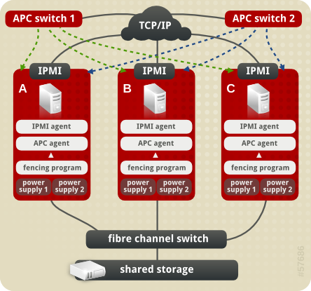
Figure 7.1. Cluster Configured with Backup Fencing Method
7.1. Backup Fencing Prerequisite Configuration
Table 7.1, “Configuration Prerequisities” summarizes the prerequisite components that have been set up before this procedure begins.
Table 7.1. Configuration Prerequisities
| Component | Name | Comment |
|---|---|---|
| cluster | backupclust | three-node cluster |
| cluster node | clusternode1.example.com | node in cluster backupclust configured with 2 APC switches, an IPMI management board, and 2 power supplies |
| cluster node | clusternode2.example.com | node in cluster backupclust configured with 2 APC switches, an IPMI management board, and 2 power supplies |
| cluster node | clusternode3.example.com | node in cluster backupclust configured with 2 APC switches, an IPMI management board, and 2 power supplies |
| IP address | 10.15.86.96 | IP address for the first APC switch that controls the power for for clusternode1.example.com, clusternode2.example.com, and clusternode3.example.com. This switch runs on its own UPS. |
| IP address | 10.15.86.97 | IP address for the second APC switch that controls the power for for clusternode1.example.com, clusternode2.example.com, and clusternode3.example.com. This switch runs on its own UPS. |
| IP address | 10.15.86.50 | IP address for IPMI management board for clusternode1.example.com |
| IP address | 10.15.86.51 | IP address for IPMI management board for clusternode2.example.com |
| IP address | 10.15.86.52 | IP address for IPMI management board for clusternode3.example.com |
Table 7.2, “Configuration Prerequisities” summarizes the prerequisite components that have been set up for each of the APC switches before this procedure begins.
Table 7.2. Configuration Prerequisities
| Component | Name | Comment |
|---|---|---|
| login | apclogin | login value for both of the the APC switches that control the power for for clusternode1.example.com, clusternode2.example.com, and clusternode3.example.com |
| password | apcpword | password for both the APC switches that control the power for for clusternode1.example.com, clusternode2.example.com, and clusternode3.example.com |
| port | 1 | port number on both of the APC switches that clusternode1.example.com connects to |
| port | 2 | port number on both of the APC switches that clusternode2.example.com connects to |
| port | 3 | port number on both of the APC switches that clusternode3.example.com connects to |
Table 7.3, “Configuration Prerequisities” summarizes the prerequisite components that have been set up for each of the IPMI management boards before this procedure begins.
Table 7.3. Configuration Prerequisities
| Component | Name | Comment |
|---|---|---|
| login | ipmilogin | login name for IPMI management board for clusternode1.example.com, clusternode2.example.com, and clusternode3.example.com |
| password | ipmipword | password IPMI management board for clusternode1.example.com, clusternode2.example.com, and clusternode3.example.com |