Chapter 6. Planning an SR-IOV deployment
Optimize single root I/O virtualization (SR-IOV) deployments for NFV by setting individual parameters based on your Compute node hardware.
To evaluate your hardware impact on the SR-IOV parameters, see Discovering your NUMA node topology.
6.1. Hardware partitioning for an SR-IOV deployment
To achieve high performance with SR-IOV, partition the resources between the host and the guest.
Figure 6.1. NUMA node topology
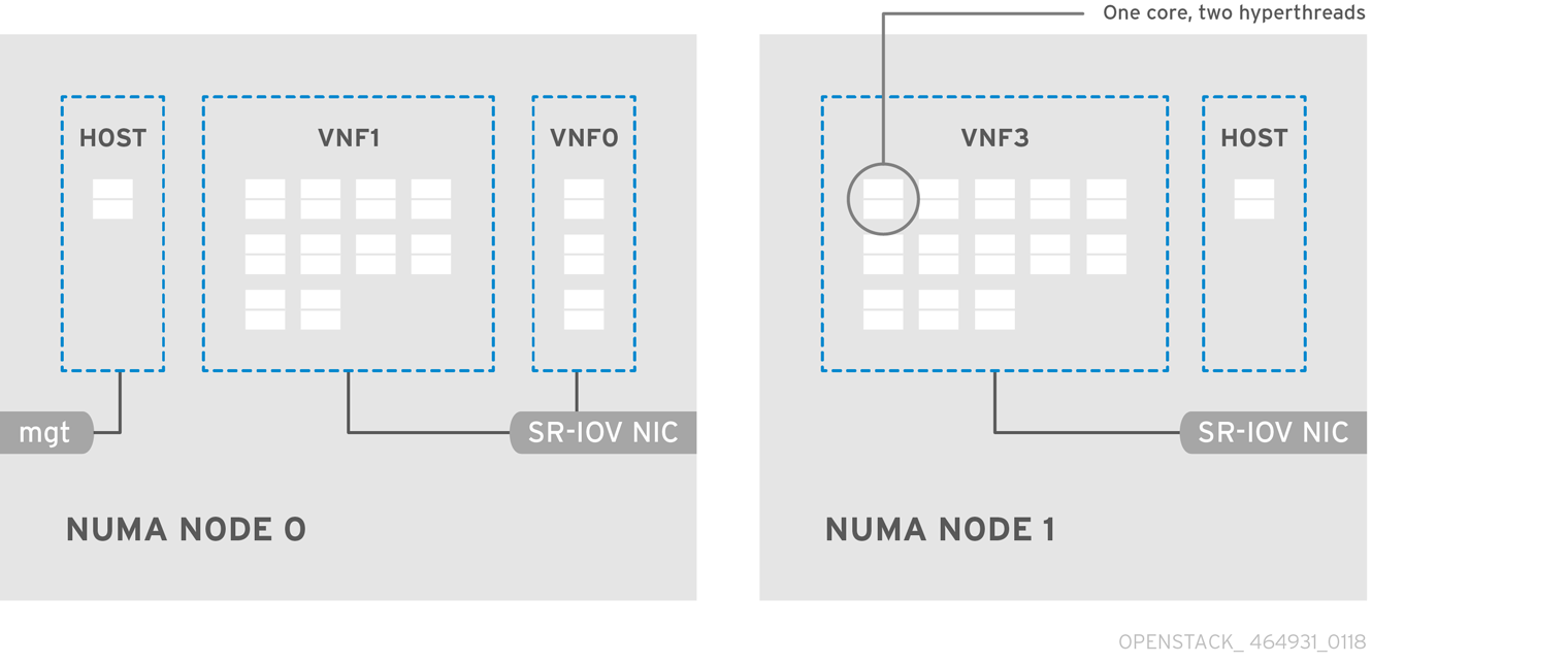
A typical topology includes 14 cores per NUMA node on dual socket Compute nodes. Both hyper-threading (HT) and non-HT cores are supported. Each core has two sibling threads. One core is dedicated to the host on each NUMA node. The virtual network function (VNF) handles the SR-IOV interface bonding. All the interrupt requests (IRQs) are routed on the host cores. The VNF cores are dedicated to the VNFs. They provide isolation from other VNFs and isolation from the host. Each VNF must use resources on a single NUMA node. The SR-IOV NICs used by the VNF must also be associated with that same NUMA node. This topology does not have a virtualization overhead. The host, OpenStack Networking (neutron), and Compute (nova) configuration parameters are exposed in a single file for ease, consistency, and to avoid incoherence that is fatal to proper isolation, causing preemption, and packet loss. The host and virtual machine isolation depend on a tuned profile, which defines the boot parameters and any Red Hat OpenStack Platform modifications based on the list of isolated CPUs.
6.2. Topology of an NFV SR-IOV deployment
The following image has two VNFs each with the management interface represented by mgt and the data plane interfaces. The management interface manages the ssh access, and so on. The data plane interfaces bond the VNFs to DPDK to ensure high availability, as VNFs bond the data plane interfaces using the DPDK library. The image also has two provider networks for redundancy. The Compute node has two regular NICs bonded together and shared between the VNF management and the Red Hat OpenStack Platform API management.
Figure 6.2. NFV SR-IOV topology
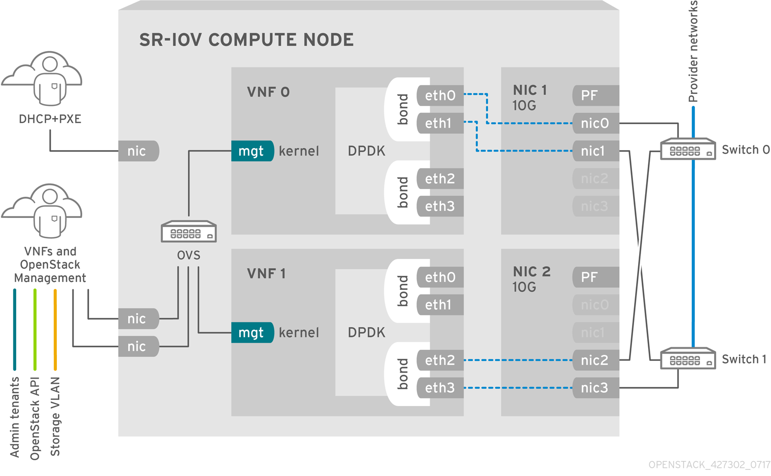
The image shows a VNF that uses DPDK at an application level, and has access to SR-IOV virtual functions (VFs) and physical functions (PFs), for better availability or performance, depending on the fabric configuration. DPDK improves performance, while the VF/PF DPDK bonds provide support for failover, and high availability. The VNF vendor must ensure that the DPDK poll mode driver (PMD) supports the SR-IOV card that is being exposed as a VF/PF. The management network uses OVS, therefore the VNF sees a mgmt network device using the standard virtIO drivers. You can use that device to initially connect to the VNF, and ensure that the DPDK application bonds the two VF/PFs.
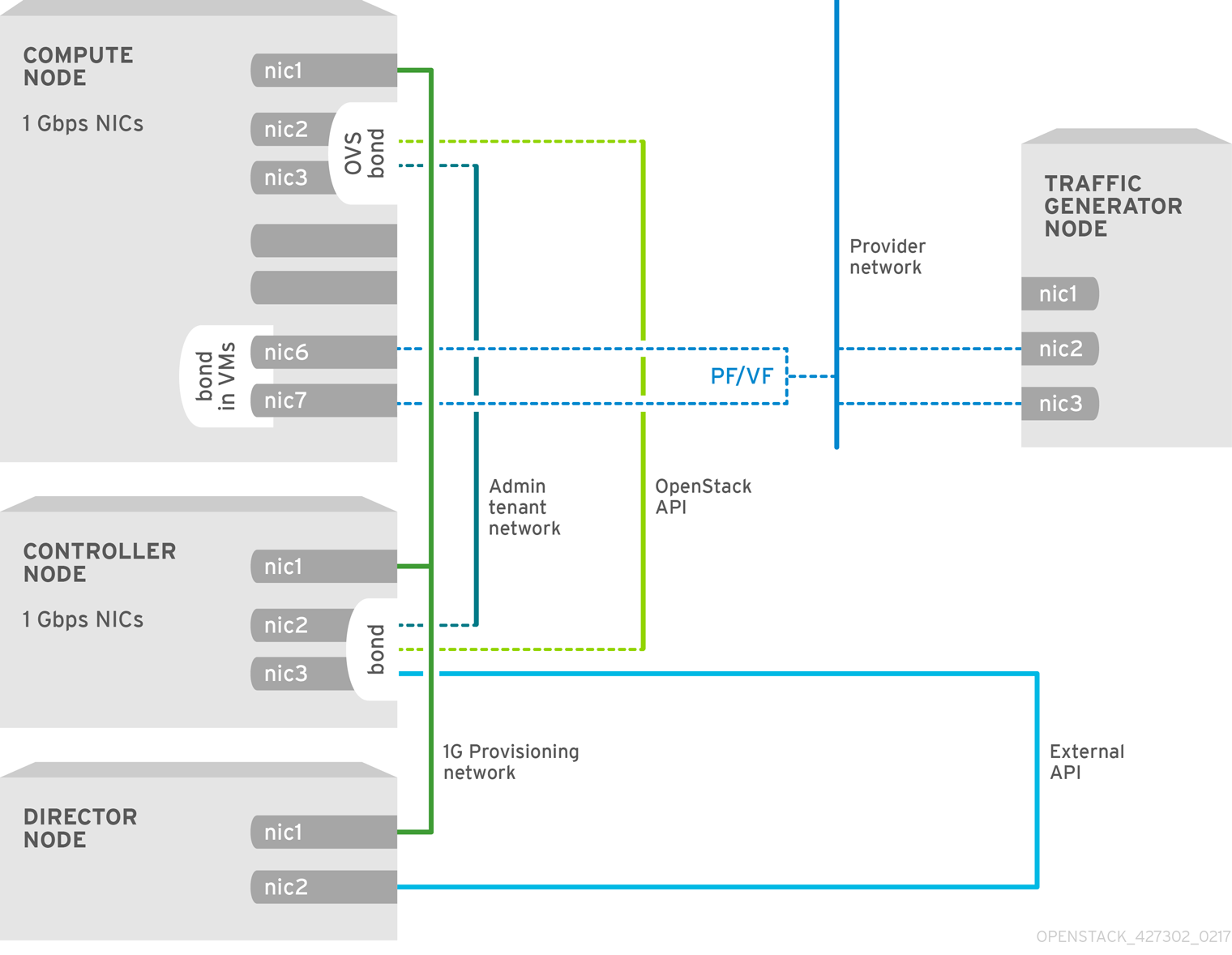
6.3. Topology for NFV SR-IOV without HCI
Observe the topology for SR-IOV without hyper-converged infrastructure (HCI) for NFV in the image below. It consists of compute and controller nodes with 1 Gbps NICs, and the director node.
Figure 6.3. NFV SR-IOV topology without HCI