
Chapter 15. OVN-Kubernetes default CNI network provider
15.1. About the OVN-Kubernetes default Container Network Interface (CNI) network provider
The OpenShift Container Platform cluster uses a virtualized network for pod and service networks. The OVN-Kubernetes Container Network Interface (CNI) plug-in is a network provider for the default cluster network. OVN-Kubernetes is based on Open Virtual Network (OVN) and provides an overlay-based networking implementation. A cluster that uses the OVN-Kubernetes network provider also runs Open vSwitch (OVS) on each node. OVN configures OVS on each node to implement the declared network configuration.
15.1.1. OVN-Kubernetes features
The OVN-Kubernetes Container Network Interface (CNI) cluster network provider implements the following features:
- Uses OVN (Open Virtual Network) to manage network traffic flows. OVN is a community developed, vendor-agnostic network virtualization solution.
- Implements Kubernetes network policy support, including ingress and egress rules.
- Uses the Geneve (Generic Network Virtualization Encapsulation) protocol rather than VXLAN to create an overlay network between nodes.
15.1.2. Supported default CNI network provider feature matrix
OpenShift Container Platform offers two supported choices, OpenShift SDN and OVN-Kubernetes, for the default Container Network Interface (CNI) network provider. The following table summarizes the current feature support for both network providers:
Table 15.1. Default CNI network provider feature comparison
| Feature | OVN-Kubernetes | OpenShift SDN |
|---|---|---|
| Egress IPs | Supported | Supported |
| Egress firewall [1] | Supported | Supported |
| Egress router | Partially supported [3] | Supported |
| IPsec encryption | Supported | Not supported |
| Kubernetes network policy | Supported | Partially supported [2] |
| Multicast | Supported | Supported |
- Egress firewall is also known as egress network policy in OpenShift SDN. This is not the same as network policy egress.
-
Network policy for OpenShift SDN does not support egress rules and some
ipBlockrules. - Egress router for OVN-Kubernetes supports only redirect mode.
15.1.3. OVN-Kubernetes limitations
The OVN-Kubernetes Container Network Interface (CNI) cluster network provider has a limitation that is related to traffic policies. The network provider does not support setting the external traffic policy or internal traffic policy for a Kubernetes service to local. The default value, cluster, is supported for both parameters. This limitation can affect you when you add a service of type LoadBalancer, NodePort, or add a service with an external IP.
15.2. Migrating from the OpenShift SDN cluster network provider
As a cluster administrator, you can migrate to the OVN-Kubernetes Container Network Interface (CNI) cluster network provider from the OpenShift SDN CNI cluster network provider.
To learn more about OVN-Kubernetes, read About the OVN-Kubernetes network provider.
15.2.1. Migration to the OVN-Kubernetes network provider
Migrating to the OVN-Kubernetes Container Network Interface (CNI) cluster network provider is a manual process that includes some downtime during which your cluster is unreachable. Although a rollback procedure is provided, the migration is intended to be a one-way process.
A migration to the OVN-Kubernetes cluster network provider is supported on installer-provisioned clusters on the following platforms:
- Bare metal hardware
- Amazon Web Services (AWS)
- Google Cloud Platform (GCP)
- Microsoft Azure
- Red Hat OpenStack Platform (RHOSP)
- VMware vSphere
Performing a migration on a user-provisioned cluster is not supported.
15.2.1.1. Considerations for migrating to the OVN-Kubernetes network provider
The subnets assigned to nodes and the IP addresses assigned to individual pods are not preserved during the migration.
While the OVN-Kubernetes network provider implements many of the capabilities present in the OpenShift SDN network provider, the configuration is not the same.
If your cluster uses any of the following OpenShift SDN capabilities, you must manually configure the same capability in OVN-Kubernetes:
- Namespace isolation
- Egress IP addresses
- Egress network policies
- Egress router pods
- Multicast
-
If your cluster uses any part of the
100.64.0.0/16IP address range, you cannot migrate to OVN-Kubernetes because it uses this IP address range internally.
The following sections highlight the differences in configuration between the aforementioned capabilities in OVN-Kubernetes and OpenShift SDN.
Namespace isolation
OVN-Kubernetes supports only the network policy isolation mode.
If your cluster uses OpenShift SDN configured in either the multitenant or subnet isolation modes, you cannot migrate to the OVN-Kubernetes network provider.
Egress IP addresses
The differences in configuring an egress IP address between OVN-Kubernetes and OpenShift SDN is described in the following table:
Table 15.2. Differences in egress IP address configuration
| OVN-Kubernetes | OpenShift SDN |
|---|---|
|
|
For more information on using egress IP addresses in OVN-Kubernetes, see "Configuring an egress IP address".
Egress network policies
The difference in configuring an egress network policy, also known as an egress firewall, between OVN-Kubernetes and OpenShift SDN is described in the following table:
Table 15.3. Differences in egress network policy configuration
| OVN-Kubernetes | OpenShift SDN |
|---|---|
|
|
For more information on using an egress firewall in OVN-Kubernetes, see "Configuring an egress firewall for a project".
Egress router pods
OVN-Kubernetes does not support using egress router pods in OpenShift Container Platform 4.7.
Multicast
The difference between enabling multicast traffic on OVN-Kubernetes and OpenShift SDN is described in the following table:
Table 15.4. Differences in multicast configuration
| OVN-Kubernetes | OpenShift SDN |
|---|---|
|
|
For more information on using multicast in OVN-Kubernetes, see "Enabling multicast for a project".
Network policies
OVN-Kubernetes fully supports the Kubernetes NetworkPolicy API in the networking.k8s.io/v1 API group. No changes are necessary in your network policies when migrating from OpenShift SDN.
15.2.1.2. How the migration process works
The migration process works as follows:
-
Set a temporary annotation set on the Cluster Network Operator (CNO) configuration object. This annotation triggers the CNO to watch for a change to the
defaultNetworkfield. - Suspend the Machine Config Operator (MCO) to ensure that it does not interrupt the migration.
-
Update the
defaultNetworkfield. The update causes the CNO to destroy the OpenShift SDN control plane pods and deploy the OVN-Kubernetes control plane pods. Additionally, it updates the Multus objects to reflect the new cluster network provider. - Reboot each node in the cluster. Because the existing pods in the cluster are unaware of the change to the cluster network provider, rebooting each node ensures that each node is drained of pods. New pods are attached to the new cluster network provided by OVN-Kubernetes.
- Enable the MCO after all nodes in the cluster reboot. The MCO rolls out an update to the systemd configuration necessary to complete the migration. The MCO updates a single machine per pool at a time by default, so the total time the migration takes increases with the size of the cluster.
15.2.2. Migrating to the OVN-Kubernetes default CNI network provider
As a cluster administrator, you can change the default Container Network Interface (CNI) network provider for your cluster to OVN-Kubernetes. During the migration, you must reboot every node in your cluster.
While performing the migration, your cluster is unavailable and workloads might be interrupted. Perform the migration only when an interruption in service is acceptable.
Prerequisites
- A cluster installed on installer-provisioned infrastructure and configured with the OpenShift SDN default CNI network provider in the network policy isolation mode.
-
Install the OpenShift CLI (
oc). -
Access to the cluster as a user with the
cluster-adminrole. - A recent backup of the etcd database is available.
- The cluster is in a known good state, without any errors.
- A reboot can be triggered manually for each node.
Procedure
To backup the configuration for the cluster network, enter the following command:
$ oc get Network.config.openshift.io cluster -o yaml > cluster-openshift-sdn.yaml
To enable the migration, set an annotation on the Cluster Network Operator configuration object by entering the following command:
$ oc annotate Network.operator.openshift.io cluster \
  'networkoperator.openshift.io/network-migration'=""
Stop all of the machine configuration pools managed by the Machine Config Operator (MCO):
Stop the master configuration pool:
$ oc patch MachineConfigPool master --type='merge' --patch \
  '{ "spec": { "paused": true } }'
Stop the worker configuration pool:
$ oc patch MachineConfigPool worker --type='merge' --patch \
  '{ "spec":{ "paused" :true } }'
Configure the OVN-Kubernetes cluster network provider by using one of the following commands:
To specify the network provider without changing the cluster network IP address block, enter the following command:
$ oc patch Network.config.openshift.io cluster \
  --type='merge' --patch '{ "spec": { "networkType": "OVNKubernetes" } }'
To specify a different cluster network IP address block, enter the following command:
$ oc patch Network.config.openshift.io cluster \
  --type='merge' --patch '{
    "spec": {
      "clusterNetwork": [
        {
          "cidr": "<cidr>",
          "hostPrefix": "<prefix>"
        }
      ],
      "networkType": "OVNKubernetes"
    }
  }'
where
cidris a CIDR block andprefixis the slice of the CIDR block apportioned to each node in your cluster. You cannot use any CIDR block that overlaps with the100.64.0.0/16CIDR block, because the OVN-Kubernetes network provider uses this block internally.ImportantYou cannot change the service network address block during the migration.
Optional: You can customize the following settings for OVN-Kubernetes to meet your network infrastructure requirements:
- Maximum transmission unit (MTU)
- Geneve (Generic Network Virtualization Encapsulation) overlay network port
To customize either of the previously noted settings, enter and customize the following command. If you do not need to change the default value, omit the key from the patch.
$ oc patch Network.operator.openshift.io cluster --type=merge \
  --patch '{
    "spec":{
      "defaultNetwork":{
        "ovnKubernetesConfig":{
          "mtu":<mtu>,
          "genevePort":<port>
    }}}}'
+
mtu-
The MTU for the Geneve overlay network. This value is normally configured automatically, but if the nodes in your cluster do not all use the same MTU, then you must set this explicitly to
100less than the smallest node MTU value. port-
The UDP port for the Geneve overlay network. If a value is not specified, the default is
6081. The port cannot be the same as the VXLAN port that is used by OpenShift SDN. The default value for the VXLAN port is4789.
+ .Example patch command to update mtu field
$ oc patch Network.operator.openshift.io cluster --type=merge \
  --patch '{
    "spec":{
      "defaultNetwork":{
        "ovnKubernetesConfig":{
          "mtu":1200
    }}}}'
Wait until the Multus daemon set rollout completes.
$ oc -n openshift-multus rollout status daemonset/multus
The name of the Multus pods is in form of
multus-<xxxxx>where<xxxxx>is a random sequence of letters. It might take several moments for the pods to restart.Example output
Waiting for daemon set "multus" rollout to finish: 1 out of 6 new pods have been updated...
...
Waiting for daemon set "multus" rollout to finish: 5 of 6 updated pods are available...
daemon set "multus" successfully rolled out
To complete the migration, reboot each node in your cluster. For example, you can use a bash script similar to the following example. The script assumes that you can connect to each host by using
sshand that you have configuredsudoto not prompt for a password.#!/bin/bash for ip in $(oc get nodes -o jsonpath='{.items[*].status.addresses[?(@.type=="InternalIP")].address}') do echo "reboot node $ip" ssh -o StrictHostKeyChecking=no core@$ip sudo shutdown -r -t 3 doneIf ssh access is not available, you might be able to reboot each node through the management portal for your infrastructure provider.
After the nodes in your cluster have rebooted, start all of the machine configuration pools:
Start the master configuration pool:
$ oc patch MachineConfigPool master --type='merge' --patch \
  '{ "spec": { "paused": false } }'
Start the worker configuration pool:
$ oc patch MachineConfigPool worker --type='merge' --patch \
  '{ "spec": { "paused": false } }'
As the MCO updates machines in each config pool, it reboots each node.
By default the MCO updates a single machine per pool at a time, so the time that the migration requires to complete grows with the size of the cluster.
Confirm the status of the new machine configuration on the hosts:
To list the machine configuration state and the name of the applied machine configuration, enter the following command:
$ oc describe node | egrep "hostname|machineconfig"
Example output
kubernetes.io/hostname=master-0
machineconfiguration.openshift.io/currentConfig: rendered-master-c53e221d9d24e1c8bb6ee89dd3d8ad7b
machineconfiguration.openshift.io/desiredConfig: rendered-master-c53e221d9d24e1c8bb6ee89dd3d8ad7b
machineconfiguration.openshift.io/reason:
machineconfiguration.openshift.io/state: Done
Verify that the following statements are true:
-
The value of
machineconfiguration.openshift.io/statefield isDone. -
The value of the
machineconfiguration.openshift.io/currentConfigfield is equal to the value of themachineconfiguration.openshift.io/desiredConfigfield.
-
The value of
To confirm that the machine config is correct, enter the following command:
$ oc get machineconfig <config_name> -o yaml | grep ExecStart
where
<config_name>is the name of the machine config from themachineconfiguration.openshift.io/currentConfigfield.The machine config must include the following update to the systemd configuration:
ExecStart=/usr/local/bin/configure-ovs.sh OVNKubernetes
Confirm that the migration succeeded:
To confirm that the default CNI network provider is OVN-Kubernetes, enter the following command. The value of
status.networkTypemust beOVNKubernetes.$ oc get network.config/cluster -o jsonpath='{.status.networkType}{"\n"}'To confirm that the cluster nodes are in the
Readystate, enter the following command:$ oc get nodes
If a node is stuck in the
NotReadystate, investigate the machine config daemon pod logs and resolve any errors.To list the pods, enter the following command:
$ oc get pod -n openshift-machine-config-operator
Example output
NAME                                         READY   STATUS    RESTARTS   AGE
machine-config-controller-75f756f89d-sjp8b   1/1     Running   0          37m
machine-config-daemon-5cf4b                  2/2     Running   0          43h
machine-config-daemon-7wzcd                  2/2     Running   0          43h
machine-config-daemon-fc946                  2/2     Running   0          43h
machine-config-daemon-g2v28                  2/2     Running   0          43h
machine-config-daemon-gcl4f                  2/2     Running   0          43h
machine-config-daemon-l5tnv                  2/2     Running   0          43h
machine-config-operator-79d9c55d5-hth92      1/1     Running   0          37m
machine-config-server-bsc8h                  1/1     Running   0          43h
machine-config-server-hklrm                  1/1     Running   0          43h
machine-config-server-k9rtx                  1/1     Running   0          43h
The names for the config daemon pods are in the following format:
machine-config-daemon-<seq>. The<seq>value is a random five character alphanumeric sequence.Display the pod log for the first machine config daemon pod shown in the previous output by enter the following command:
$ oc logs <pod> -n openshift-machine-config-operator
where
podis the name of a machine config daemon pod.- Resolve any errors in the logs shown by the output from the previous command.
To confirm that your pods are not in an error state, enter the following command:
$ oc get pods --all-namespaces -o wide --sort-by='{.spec.nodeName}'If pods on a node are in an error state, reboot that node.
Complete the following steps only if the migration succeeds and your cluster is in a good state:
To remove the migration annotation from the Cluster Network Operator configuration object, enter the following command:
$ oc annotate Network.operator.openshift.io cluster \
  networkoperator.openshift.io/network-migration-
To remove the OpenShift SDN network provider namespace, enter the following command:
$ oc delete namespace openshift-sdn
15.2.3. Additional resources
- Configuration parameters for the OVN-Kubernetes default CNI network provider
- Backing up etcd
- About network policy
OVN-Kubernetes capabilities
OpenShift SDN capabilities
- Network [operator.openshift.io/v1]
15.3. Rolling back to the OpenShift SDN network provider
As a cluster administrator, you can rollback to the OpenShift SDN Container Network Interface (CNI) cluster network provider from the OVN-Kubernetes CNI cluster network provider if the migration to OVN-Kubernetes is unsuccessful.
15.3.1. Rolling back the default CNI network provider to OpenShift SDN
As a cluster administrator, you can rollback your cluster to the OpenShift SDN default Container Network Interface (CNI) network provider. During the rollback, you must reboot every node in your cluster.
Only rollback to OpenShift SDN if the migration to OVN-Kubernetes fails.
Prerequisites
-
Install the OpenShift CLI (
oc). -
Access to the cluster as a user with the
cluster-adminrole. - A cluster installed on infrastructure configured with the OVN-Kubernetes default CNI network provider.
Procedure
To enable the migration, set an annotation on the Cluster Network Operator configuration object by entering the following command:
$ oc annotate Network.operator.openshift.io cluster \
  'networkoperator.openshift.io/network-migration'=""
Stop all of the machine configuration pools managed by the Machine Config Operator (MCO):
Stop the master configuration pool:
$ oc patch MachineConfigPool master --type='merge' --patch \
  '{ "spec": { "paused": true } }'
Stop the worker configuration pool:
$ oc patch MachineConfigPool worker --type='merge' --patch \
  '{ "spec":{ "paused" :true } }'
To configure the OpenShift SDN cluster network provider, enter the following command:
$ oc patch Network.config.openshift.io cluster \
  --type='merge' --patch '{ "spec": { "networkType": "OpenShiftSDN" } }'
Optional: You can customize the following settings for OpenShift SDN to meet your network infrastructure requirements:
- Maximum transmission unit (MTU)
- VXLAN port
To customize either or both of the previously noted settings, customize and enter the following command. If you do not need to change the default value, omit the key from the patch.
$ oc patch Network.operator.openshift.io cluster --type=merge \ --patch '{ "spec":{ "defaultNetwork":{ "openshiftSDNConfig":{ "mtu":<mtu>, "vxlanPort":<port> }}}}'mtu-
The MTU for the VXLAN overlay network. This value is normally configured automatically, but if the nodes in your cluster do not all use the same MTU, then you must set this explicitly to
50less than the smallest node MTU value. port-
The UDP port for the VXLAN overlay network. If a value is not specified, the default is
4789. The port cannot be the same as the Geneve port that is used by OVN-Kubernetes. The default value for the Geneve port is6081.
Example patch command
$ oc patch Network.operator.openshift.io cluster --type=merge \
  --patch '{
    "spec":{
      "defaultNetwork":{
        "openshiftSDNConfig":{
          "mtu":1200
    }}}}'
Wait until the Multus daemon set rollout completes.
$ oc -n openshift-multus rollout status daemonset/multus
The name of the Multus pods is in form of
multus-<xxxxx>where<xxxxx>is a random sequence of letters. It might take several moments for the pods to restart.Example output
Waiting for daemon set "multus" rollout to finish: 1 out of 6 new pods have been updated...
...
Waiting for daemon set "multus" rollout to finish: 5 of 6 updated pods are available...
daemon set "multus" successfully rolled out
To complete the rollback, reboot each node in your cluster. For example, you could use a bash script similar to the following. The script assumes that you can connect to each host by using
sshand that you have configuredsudoto not prompt for a password.#!/bin/bash for ip in $(oc get nodes -o jsonpath='{.items[*].status.addresses[?(@.type=="InternalIP")].address}') do echo "reboot node $ip" ssh -o StrictHostKeyChecking=no core@$ip sudo shutdown -r -t 3 doneIf ssh access is not available, you might be able to reboot each node through the management portal for your infrastructure provider.
After the nodes in your cluster have rebooted, start all of the machine configuration pools:
Start the master configuration pool:
$ oc patch MachineConfigPool master --type='merge' --patch \
  '{ "spec": { "paused": false } }'
Start the worker configuration pool:
$ oc patch MachineConfigPool worker --type='merge' --patch \
  '{ "spec": { "paused": false } }'
As the MCO updates machines in each config pool, it reboots each node.
By default the MCO updates a single machine per pool at a time, so the time that the migration requires to complete grows with the size of the cluster.
Confirm the status of the new machine configuration on the hosts:
To list the machine configuration state and the name of the applied machine configuration, enter the following command:
$ oc describe node | egrep "hostname|machineconfig"
Example output
kubernetes.io/hostname=master-0
machineconfiguration.openshift.io/currentConfig: rendered-master-c53e221d9d24e1c8bb6ee89dd3d8ad7b
machineconfiguration.openshift.io/desiredConfig: rendered-master-c53e221d9d24e1c8bb6ee89dd3d8ad7b
machineconfiguration.openshift.io/reason:
machineconfiguration.openshift.io/state: Done
Verify that the following statements are true:
-
The value of
machineconfiguration.openshift.io/statefield isDone. -
The value of the
machineconfiguration.openshift.io/currentConfigfield is equal to the value of themachineconfiguration.openshift.io/desiredConfigfield.
-
The value of
To confirm that the machine config is correct, enter the following command:
$ oc get machineconfig <config_name> -o yaml
where
<config_name>is the name of the machine config from themachineconfiguration.openshift.io/currentConfigfield.
Confirm that the migration succeeded:
To confirm that the default CNI network provider is OVN-Kubernetes, enter the following command. The value of
status.networkTypemust beOpenShiftSDN.$ oc get network.config/cluster -o jsonpath='{.status.networkType}{"\n"}'To confirm that the cluster nodes are in the
Readystate, enter the following command:$ oc get nodes
If a node is stuck in the
NotReadystate, investigate the machine config daemon pod logs and resolve any errors.To list the pods, enter the following command:
$ oc get pod -n openshift-machine-config-operator
Example output
NAME                                         READY   STATUS    RESTARTS   AGE
machine-config-controller-75f756f89d-sjp8b   1/1     Running   0          37m
machine-config-daemon-5cf4b                  2/2     Running   0          43h
machine-config-daemon-7wzcd                  2/2     Running   0          43h
machine-config-daemon-fc946                  2/2     Running   0          43h
machine-config-daemon-g2v28                  2/2     Running   0          43h
machine-config-daemon-gcl4f                  2/2     Running   0          43h
machine-config-daemon-l5tnv                  2/2     Running   0          43h
machine-config-operator-79d9c55d5-hth92      1/1     Running   0          37m
machine-config-server-bsc8h                  1/1     Running   0          43h
machine-config-server-hklrm                  1/1     Running   0          43h
machine-config-server-k9rtx                  1/1     Running   0          43h
The names for the config daemon pods are in the following format:
machine-config-daemon-<seq>. The<seq>value is a random five character alphanumeric sequence.To display the pod log for each machine config daemon pod shown in the previous output, enter the following command:
$ oc logs <pod> -n openshift-machine-config-operator
where
podis the name of a machine config daemon pod.- Resolve any errors in the logs shown by the output from the previous command.
To confirm that your pods are not in an error state, enter the following command:
$ oc get pods --all-namespaces -o wide --sort-by='{.spec.nodeName}'If pods on a node are in an error state, reboot that node.
Complete the following steps only if the migration succeeds and your cluster is in a good state:
To remove the migration annotation from the Cluster Network Operator configuration object, enter the following command:
$ oc annotate Network.operator.openshift.io cluster \
  networkoperator.openshift.io/network-migration-
To remove the OVN-Kubernetes network provider namespace, enter the following command:
$ oc delete namespace openshift-ovn-kubernetes
15.4. IPsec encryption configuration
With IPsec enabled, all network traffic between nodes on the OVN-Kubernetes Container Network Interface (CNI) cluster network travels through an encrypted tunnel.
IPsec is disabled by default.
IPsec encryption can be enabled only during cluster installation and cannot be disabled after it is enabled. For installation documentation, refer to Selecting a cluster installation method and preparing it for users.
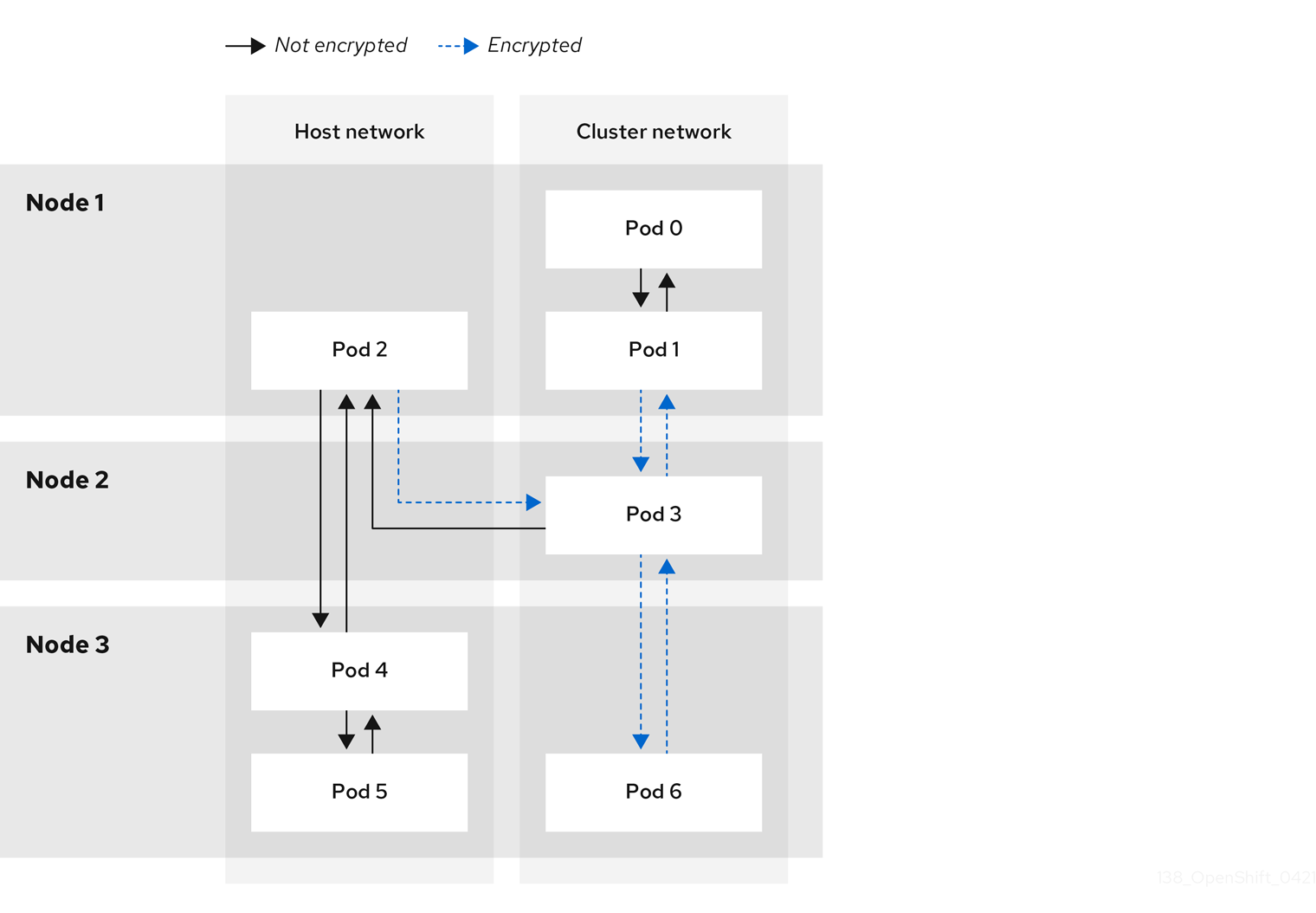
15.4.1. Types of network traffic flows encrypted by IPsec
With IPsec enabled, only the following network traffic flows between pods are encrypted:
- Traffic between pods on different nodes on the cluster network
- Traffic from a pod on the host network to a pod on the cluster network
The following traffic flows are not encrypted:
- Traffic between pods on the same node on the cluster network
- Traffic between pods on the host network
- Traffic from a pod on the cluster network to a pod on the host network
The encrypted and unencrypted flows are illustrated in the following diagram:
15.4.2. Encryption protocol and tunnel mode for IPsec
The encrypt cipher used is AES-GCM-16-256. The integrity check value (ICV) is 16 bytes. The key length is 256 bits.
The IPsec tunnel mode used is Transport mode, a mode that encrypts end-to-end communication.
15.4.3. Security certificate generation and rotation
The Cluster Network Operator (CNO) generates a self-signed X.509 certificate authority (CA) that is used by IPsec for encryption. Certificate signing requests (CSRs) from each node are automatically fulfilled by the CNO.
The CA is valid for 10 years. The individual node certificates are valid for 5 years and are automatically rotated after 4 1/2 years elapse.
15.5. Configuring an egress firewall for a project
As a cluster administrator, you can create an egress firewall for a project that restricts egress traffic leaving your OpenShift Container Platform cluster.
15.5.1. How an egress firewall works in a project
As a cluster administrator, you can use an egress firewall to limit the external hosts that some or all pods can access from within the cluster. An egress firewall supports the following scenarios:
- A pod can only connect to internal hosts and cannot initiate connections to the public Internet.
- A pod can only connect to the public Internet and cannot initiate connections to internal hosts that are outside the OpenShift Container Platform cluster.
- A pod cannot reach specified internal subnets or hosts outside the OpenShift Container Platform cluster.
- A pod can connect to only specific external hosts.
For example, you can allow one project access to a specified IP range but deny the same access to a different project. Or you can restrict application developers from updating from Python pip mirrors, and force updates to come only from approved sources.
You configure an egress firewall policy by creating an EgressFirewall custom resource (CR) object. The egress firewall matches network traffic that meets any of the following criteria:
- An IP address range in CIDR format
- A DNS name that resolves to an IP address
- A port number
- A protocol that is one of the following protocols: TCP, UDP, and SCTP
If your egress firewall includes a deny rule for 0.0.0.0/0, access to your OpenShift Container Platform API servers is blocked. To ensure that pods can continue to access the OpenShift Container Platform API servers, you must include the IP address range that the API servers listen on in your egress firewall rules, as in the following example:
apiVersion: k8s.ovn.org/v1
kind: EgressFirewall
metadata:
  name: default
  namespace: <namespace> 1
spec:
  egress:
  - to:
      cidrSelector: <api_server_address_range> 2
    type: Allow
# ...
  - to:
      cidrSelector: 0.0.0.0/0 3
    type: Deny
To find the IP address for your API servers, run oc get ep kubernetes -n default.
For more information, see BZ#1988324.
Egress firewall rules do not apply to traffic that goes through routers. Any user with permission to create a Route CR object can bypass egress firewall policy rules by creating a route that points to a forbidden destination.
15.5.1.1. Limitations of an egress firewall
An egress firewall has the following limitations:
- No project can have more than one EgressFirewall object.
- A maximum of one EgressFirewall object with a maximum of 8,000 rules can be defined per project.
Violating any of these restrictions results in a broken egress firewall for the project, and may cause all external network traffic to be dropped.
An Egress Firewall resource can be created in the kube-node-lease, kube-public, kube-system, openshift and openshift- projects.
15.5.1.2. Matching order for egress firewall policy rules
The egress firewall policy rules are evaluated in the order that they are defined, from first to last. The first rule that matches an egress connection from a pod applies. Any subsequent rules are ignored for that connection.
15.5.1.3. How Domain Name Server (DNS) resolution works
If you use DNS names in any of your egress firewall policy rules, proper resolution of the domain names is subject to the following restrictions:
- Domain name updates are polled based on the TTL (time to live) value of the domain returned by the local non-authoritative servers.
- The pod must resolve the domain from the same local name servers when necessary. Otherwise the IP addresses for the domain known by the egress firewall controller and the pod can be different. If the IP addresses for a hostname differ, the egress firewall might not be enforced consistently.
- Because the egress firewall controller and pods asynchronously poll the same local name server, the pod might obtain the updated IP address before the egress controller does, which causes a race condition. Due to this current limitation, domain name usage in EgressFirewall objects is only recommended for domains with infrequent IP address changes.
The egress firewall always allows pods access to the external interface of the node that the pod is on for DNS resolution.
If you use domain names in your egress firewall policy and your DNS resolution is not handled by a DNS server on the local node, then you must add egress firewall rules that allow access to your DNS server’s IP addresses. if you are using domain names in your pods.
15.5.2. EgressFirewall custom resource (CR) object
You can define one or more rules for an egress firewall. A rule is either an Allow rule or a Deny rule, with a specification for the traffic that the rule applies to.
The following YAML describes an EgressFirewall CR object:
EgressFirewall object
apiVersion: k8s.ovn.org/v1
kind: EgressFirewall
metadata:
  name: <name> 1
spec:
  egress: 2
    ...
15.5.2.1. EgressFirewall rules
The following YAML describes an egress firewall rule object. The egress stanza expects an array of one or more objects.
Egress policy rule stanza
egress:
- type: <type> 1
  to: 2
    cidrSelector: <cidr> 3
    dnsName: <dns_name> 4
  ports: 5
      ...
- 1
- The type of rule. The value must be either
AlloworDeny. - 2
- A stanza describing an egress traffic match rule that specifies the
cidrSelectorfield or thednsNamefield. You cannot use both fields in the same rule. - 3
- An IP address range in CIDR format.
- 4
- A DNS domain name.
- 5
- Optional: A stanza describing a collection of network ports and protocols for the rule.
Ports stanza
ports:
- port: <port> 1
  protocol: <protocol> 2
15.5.2.2. Example EgressFirewall CR objects
The following example defines several egress firewall policy rules:
apiVersion: k8s.ovn.org/v1
kind: EgressFirewall
metadata:
  name: default
spec:
  egress: 1
  - type: Allow
    to:
      cidrSelector: 1.2.3.0/24
  - type: Deny
    to:
cidrSelector: 0.0.0.0/0- 1
- A collection of egress firewall policy rule objects.
The following example defines a policy rule that denies traffic to the host at the 172.16.1.1 IP address, if the traffic is using either the TCP protocol and destination port 80 or any protocol and destination port 443.
apiVersion: k8s.ovn.org/v1
kind: EgressFirewall
metadata:
  name: default
spec:
  egress:
  - type: Deny
    to:
      cidrSelector: 172.16.1.1
    ports:
    - port: 80
      protocol: TCP
    - port: 443
15.5.3. Creating an egress firewall policy object
As a cluster administrator, you can create an egress firewall policy object for a project.
If the project already has an EgressFirewall object defined, you must edit the existing policy to make changes to the egress firewall rules.
Prerequisites
- A cluster that uses the OVN-Kubernetes default Container Network Interface (CNI) network provider plug-in.
-
Install the OpenShift CLI (
oc). - You must log in to the cluster as a cluster administrator.
Procedure
Create a policy rule:
-
Create a
<policy_name>.yamlfile where<policy_name>describes the egress policy rules. - In the file you created, define an egress policy object.
-
Create a
Enter the following command to create the policy object. Replace
<policy_name>with the name of the policy and<project>with the project that the rule applies to.$ oc create -f <policy_name>.yaml -n <project>
In the following example, a new EgressFirewall object is created in a project named
project1:$ oc create -f default.yaml -n project1
Example output
egressfirewall.k8s.ovn.org/v1 created
-
Optional: Save the
<policy_name>.yamlfile so that you can make changes later.
15.6. Viewing an egress firewall for a project
As a cluster administrator, you can list the names of any existing egress firewalls and view the traffic rules for a specific egress firewall.
15.6.1. Viewing an EgressFirewall object
You can view an EgressFirewall object in your cluster.
Prerequisites
- A cluster using the OVN-Kubernetes default Container Network Interface (CNI) network provider plug-in.
-
Install the OpenShift Command-line Interface (CLI), commonly known as
oc. - You must log in to the cluster.
Procedure
Optional: To view the names of the EgressFirewall objects defined in your cluster, enter the following command:
$ oc get egressfirewall --all-namespaces
To inspect a policy, enter the following command. Replace
<policy_name>with the name of the policy to inspect.$ oc describe egressfirewall <policy_name>
Example output
Name:		default
Namespace:	project1
Created:	20 minutes ago
Labels:		<none>
Annotations:	<none>
Rule:		Allow to 1.2.3.0/24
Rule:		Allow to www.example.com
Rule:		Deny to 0.0.0.0/0
15.7. Editing an egress firewall for a project
As a cluster administrator, you can modify network traffic rules for an existing egress firewall.
15.7.1. Editing an EgressFirewall object
As a cluster administrator, you can update the egress firewall for a project.
Prerequisites
- A cluster using the OVN-Kubernetes default Container Network Interface (CNI) network provider plug-in.
-
Install the OpenShift CLI (
oc). - You must log in to the cluster as a cluster administrator.
Procedure
Find the name of the EgressFirewall object for the project. Replace
<project>with the name of the project.$ oc get -n <project> egressfirewall
Optional: If you did not save a copy of the EgressFirewall object when you created the egress network firewall, enter the following command to create a copy.
$ oc get -n <project> egressfirewall <name> -o yaml > <filename>.yaml
Replace
<project>with the name of the project. Replace<name>with the name of the object. Replace<filename>with the name of the file to save the YAML to.After making changes to the policy rules, enter the following command to replace the EgressFirewall object. Replace
<filename>with the name of the file containing the updated EgressFirewall object.$ oc replace -f <filename>.yaml
15.8. Removing an egress firewall from a project
As a cluster administrator, you can remove an egress firewall from a project to remove all restrictions on network traffic from the project that leaves the OpenShift Container Platform cluster.
15.8.1. Removing an EgressFirewall object
As a cluster administrator, you can remove an egress firewall from a project.
Prerequisites
- A cluster using the OVN-Kubernetes default Container Network Interface (CNI) network provider plug-in.
-
Install the OpenShift CLI (
oc). - You must log in to the cluster as a cluster administrator.
Procedure
Find the name of the EgressFirewall object for the project. Replace
<project>with the name of the project.$ oc get -n <project> egressfirewall
Enter the following command to delete the EgressFirewall object. Replace
<project>with the name of the project and<name>with the name of the object.$ oc delete -n <project> egressfirewall <name>
15.9. Configuring an egress IP address
As a cluster administrator, you can configure the OVN-Kubernetes default Container Network Interface (CNI) network provider to assign one or more egress IP addresses to a namespace, or to specific pods in a namespace.
15.9.1. Egress IP address architectural design and implementation
The OpenShift Container Platform egress IP address functionality allows you to ensure that the traffic from one or more pods in one or more namespaces has a consistent source IP address for services outside the cluster network.
For example, you might have a pod that periodically queries a database that is hosted on a server outside of your cluster. To enforce access requirements for the server, a packet filtering device is configured to allow traffic only from specific IP addresses. To ensure that you can reliably allow access to the server from only that specific pod, you can configure a specific egress IP address for the pod that makes the requests to the server.
An egress IP address is implemented as an additional IP address on the primary network interface of a node and must be in the same subnet as the primary IP address of the node. The additional IP address must not be assigned to any other node in the cluster.
In some cluster configurations, application pods and ingress router pods run on the same node. If you configure an egress IP for an application project in this scenario, the IP is not used when you send a request to a route from the application project.
15.9.1.1. Platform support
Support for the egress IP address functionality on various platforms is summarized in the following table:
The egress IP address implementation is not compatible with Amazon Web Services (AWS), Azure Cloud, or any other public cloud platform incompatible with the automatic layer 2 network manipulation required by the egress IP feature.
| Platform | Supported |
|---|---|
| Bare metal | Yes |
| vSphere | Yes |
| Red Hat OpenStack Platform (RHOSP) | No |
| Public cloud | No |
15.9.1.2. Assignment of egress IPs to pods
To assign one or more egress IPs to a namespace or specific pods in a namespace, the following conditions must be satisfied:
-
At least one node in your cluster must have the
k8s.ovn.org/egress-assignable: ""label. -
An
EgressIPobject exists that defines one or more egress IP addresses to use as the source IP address for traffic leaving the cluster from pods in a namespace.
If you create EgressIP objects prior to labeling any nodes in your cluster for egress IP assignment, OpenShift Container Platform might assign every egress IP address to the first node with the k8s.ovn.org/egress-assignable: "" label.
To ensure that egress IP addresses are widely distributed across nodes in the cluster, always apply the label to the nodes you intent to host the egress IP addresses before creating any EgressIP objects.
15.9.1.3. Assignment of egress IPs to nodes
When creating an EgressIP object, the following conditions apply to nodes that are labeled with the k8s.ovn.org/egress-assignable: "" label:
- An egress IP address is never assigned to more than one node at a time.
- An egress IP address is equally balanced between available nodes that can host the egress IP address.
-
If the
spec.EgressIPsarray in anEgressIPobject specifies more than one IP address, no node will ever host more than one of the specified addresses. - If a node becomes unavailable, any egress IP addresses assigned to it are automatically reassigned, subject to the previously described conditions.
When a pod matches the selector for multiple EgressIP objects, there is no guarantee which of the egress IP addresses that are specified in the EgressIP objects is assigned as the egress IP address for the pod.
Additionally, if an EgressIP object specifies multiple egress IP addresses, there is no guarantee which of the egress IP addresses might be used. For example, if a pod matches a selector for an EgressIP object with two egress IP addresses, 10.10.20.1 and 10.10.20.2, either might be used for each TCP connection or UDP conversation.
15.9.1.4. Architectural diagram of an egress IP address configuration
The following diagram depicts an egress IP address configuration. The diagram describes four pods in two different namespaces running on three nodes in a cluster. The nodes are assigned IP addresses from the 192.168.126.0/18 CIDR block on the host network.
Both Node 1 and Node 3 are labeled with k8s.ovn.org/egress-assignable: "" and thus available for the assignment of egress IP addresses.
The dashed lines in the diagram depict the traffic flow from pod1, pod2, and pod3 traveling through the pod network to egress the cluster from Node 1 and Node 3. When an external service receives traffic from any of the pods selected by the example EgressIP object, the source IP address is either 192.168.126.10 or 192.168.126.102.
The following resources from the diagram are illustrated in detail:
NamespaceobjectsThe namespaces are defined in the following manifest:
Namespace objects
apiVersion: v1 kind: Namespace metadata: name: namespace1 labels: env: prod --- apiVersion: v1 kind: Namespace metadata: name: namespace2 labels: env: prodEgressIPobjectThe following
EgressIPobject describes a configuration that selects all pods in any namespace with theenvlabel set toprod. The egress IP addresses for the selected pods are192.168.126.10and192.168.126.102.EgressIPobjectapiVersion: k8s.ovn.org/v1 kind: EgressIP metadata: name: egressips-prod spec: egressIPs: - 192.168.126.10 - 192.168.126.102 namespaceSelector: matchLabels: env: prod status: assignments: - node: node1 egressIP: 192.168.126.10 - node: node3 egressIP: 192.168.126.102For the configuration in the previous example, OpenShift Container Platform assigns both egress IP addresses to the available nodes. The
statusfield reflects whether and where the egress IP addresses are assigned.
15.9.2. EgressIP object
The following YAML describes the API for the EgressIP object. The scope of the object is cluster-wide; it is not created in a namespace.
apiVersion: k8s.ovn.org/v1
kind: EgressIP
metadata:
  name: <name> 1
spec:
  egressIPs: 2
  - <ip_address>
  namespaceSelector: 3
    ...
  podSelector: 4
    ...
- 1
- The name for the
EgressIPsobject. - 2
- An array of one or more IP addresses.
- 3
- One or more selectors for the namespaces to associate the egress IP addresses with.
- 4
- Optional: One or more selectors for pods in the specified namespaces to associate egress IP addresses with. Applying these selectors allows for the selection of a subset of pods within a namespace.
The following YAML describes the stanza for the namespace selector:
Namespace selector stanza
namespaceSelector: 1
  matchLabels:
    <label_name>: <label_value>
- 1
- One or more matching rules for namespaces. If more than one match rule is provided, all matching namespaces are selected.
The following YAML describes the optional stanza for the pod selector:
Pod selector stanza
podSelector: 1
  matchLabels:
    <label_name>: <label_value>
- 1
- Optional: One or more matching rules for pods in the namespaces that match the specified
namespaceSelectorrules. If specified, only pods that match are selected. Others pods in the namespace are not selected.
In the following example, the EgressIP object associates the 192.168.126.11 and 192.168.126.102 egress IP addresses with pods that have the app label set to web and are in the namespaces that have the env label set to prod:
Example EgressIP object
apiVersion: k8s.ovn.org/v1
kind: EgressIP
metadata:
  name: egress-group1
spec:
  egressIPs:
  - 192.168.126.11
  - 192.168.126.102
  podSelector:
    matchLabels:
      app: web
  namespaceSelector:
    matchLabels:
      env: prod
In the following example, the EgressIP object associates the 192.168.127.30 and 192.168.127.40 egress IP addresses with any pods that do not have the environment label set to development:
Example EgressIP object
apiVersion: k8s.ovn.org/v1
kind: EgressIP
metadata:
  name: egress-group2
spec:
  egressIPs:
  - 192.168.127.30
  - 192.168.127.40
  namespaceSelector:
    matchExpressions:
    - key: environment
      operator: NotIn
      values:
      - development
15.9.3. Labeling a node to host egress IP addresses
You can apply the k8s.ovn.org/egress-assignable="" label to a node in your cluster so that OpenShift Container Platform can assign one or more egress IP addresses to the node.
Prerequisites
-
Install the OpenShift CLI (
oc). - Log in to the cluster as a cluster administrator.
Procedure
To label a node so that it can host one or more egress IP addresses, enter the following command:
$ oc label nodes <node_name> k8s.ovn.org/egress-assignable="" 1- 1
- The name of the node to label.
15.9.4. Next steps
15.9.5. Additional resources
15.10. Assigning an egress IP address
As a cluster administrator, you can assign an egress IP address for traffic leaving the cluster from a namespace or from specific pods in a namespace.
15.10.1. Assigning an egress IP address to a namespace
You can assign one or more egress IP addresses to a namespace or to specific pods in a namespace.
Prerequisites
-
Install the OpenShift CLI (
oc). - Log in to the cluster as a cluster administrator.
- Configure at least one node to host an egress IP address.
Procedure
Create an
EgressIPobject:-
Create a
<egressips_name>.yamlfile where<egressips_name>is the name of the object. In the file that you created, define an
EgressIPobject, as in the following example:apiVersion: k8s.ovn.org/v1 kind: EgressIP metadata: name: egress-project1 spec: egressIPs: - 192.168.127.10 - 192.168.127.11 namespaceSelector: matchLabels: env: qa
-
Create a
To create the object, enter the following command.
$ oc apply -f <egressips_name>.yaml 1- 1
- Replace
<egressips_name>with the name of the object.
Example output
egressips.k8s.ovn.org/<egressips_name> created
-
Optional: Save the
<egressips_name>.yamlfile so that you can make changes later. Add labels to the namespace that requires egress IP addresses. To add a label to the namespace of an
EgressIPobject defined in step 1, run the following command:$ oc label ns <namespace> env=qa 1- 1
- Replace
<namespace>with the namespace that requires egress IP addresses.
15.10.2. Additional resources
15.11. Considerations for the use of an egress router pod
15.11.1. About an egress router pod
The OpenShift Container Platform egress router pod redirects traffic to a specified remote server from a private source IP address that is not used for any other purpose. An egress router pod enables you to send network traffic to servers that are set up to allow access only from specific IP addresses.
The egress router pod is not intended for every outgoing connection. Creating large numbers of egress router pods can exceed the limits of your network hardware. For example, creating an egress router pod for every project or application could exceed the number of local MAC addresses that the network interface can handle before reverting to filtering MAC addresses in software.
The egress router image is not compatible with Amazon AWS, Azure Cloud, or any other cloud platform that does not support layer 2 manipulations due to their incompatibility with macvlan traffic.
15.11.1.1. Egress router modes
In redirect mode, an egress router pod configures iptables rules to redirect traffic from its own IP address to one or more destination IP addresses. Client pods that need to use the reserved source IP address must be modified to connect to the egress router rather than connecting directly to the destination IP.
The egress router CNI plug-in supports redirect mode only. This is a difference with the egress router implementation that you can deploy with OpenShift SDN. Unlike the egress router for OpenShift SDN, the egress router CNI plug-in does not support HTTP proxy mode or DNS proxy mode.
15.11.1.2. Egress router pod implementation
The egress router implementation uses the egress router Container Network Interface (CNI) plug-in. The plug-in adds a secondary network interface to a pod.
An egress router is a pod that has two network interfaces. For example, the pod can have eth0 and net1 network interfaces. The eth0 interface is on the cluster network and the pod continues to use the interface for ordinary cluster-related network traffic. The net1 interface is on a secondary network and has an IP address and gateway for that network. Other pods in the OpenShift Container Platform cluster can access the egress router service and the service enables the pods to access external services. The egress router acts as a bridge between pods and an external system.
Traffic that leaves the egress router exits through a node, but the packets have the MAC address of the net1 interface from the egress router pod.
15.11.1.3. Deployment considerations
An egress router pod adds an additional IP address and MAC address to the primary network interface of the node. As a result, you might need to configure your hypervisor or cloud provider to allow the additional address.
- Red Hat OpenStack Platform (RHOSP)
If you deploy OpenShift Container Platform on RHOSP, you must allow traffic from the IP and MAC addresses of the egress router pod on your OpenStack environment. If you do not allow the traffic, then communication will fail:
$ openstack port set --allowed-address \
  ip_address=<ip_address>,mac_address=<mac_address> <neutron_port_uuid>
- Red Hat Virtualization (RHV)
- If you are using RHV, you must select No Network Filter for the Virtual network interface controller (vNIC).
- VMware vSphere
- If you are using VMware vSphere, see the VMware documentation for securing vSphere standard switches. View and change VMware vSphere default settings by selecting the host virtual switch from the vSphere Web Client.
Specifically, ensure that the following are enabled:
15.11.1.4. Failover configuration
To avoid downtime, you can deploy an egress router pod with a Deployment resource, as in the following example. To create a new Service object for the example deployment, use the oc expose deployment/egress-demo-controller command.
apiVersion: apps/v1
kind: Deployment
metadata:
  name: egress-demo-controller
spec:
  replicas: 1  1
  selector:
    matchLabels:
      name: egress-router
  template:
    metadata:
      name: egress-router
      labels:
        name: egress-router
      annotations:
        k8s.v1.cni.cncf.io/networks: egress-router-redirect
    spec:  2
      containers:
        - name: egress-router-redirect
          image: registry.redhat.io/openshift3/ose-pod
15.11.2. Additional resources
15.12. Deploying an egress router pod in redirect mode
As a cluster administrator, you can deploy an egress router pod to redirect traffic to specified destination IP addresses from a reserved source IP address.
The egress router implementation uses the egress router Container Network Interface (CNI) plug-in.
The egress router CNI plug-in is a Technology Preview feature only. Technology Preview features are not supported with Red Hat production service level agreements (SLAs) and might not be functionally complete. Red Hat does not recommend using them in production. These features provide early access to upcoming product features, enabling customers to test functionality and provide feedback during the development process.
For more information about the support scope of Red Hat Technology Preview features, see https://access.redhat.com/support/offerings/techpreview/.
15.12.1. Network attachment definition for an egress router in redirect mode
Before a pod can act as an egress router, you must specify the network interface configuration as a NetworkAttachmentDefinition object. The object specifies information such as the IP address to attach to the egress router pod, the network destinations, and a network gateway. As the pod for the egress router starts, Multus uses the network attachment definition to add a network interface with the specified properties to the pod.
Example network attachment definition
apiVersion: "k8s.cni.cncf.io/v1"
kind: NetworkAttachmentDefinition
metadata:
  name: egress-router-redirect  <.>
spec:
  config: '{
    "cniVersion": "0.4.0",
    "type": "egress-router",
    "name": "egress-router",
    "ip": {
      "addresses": [
        "192.168.12.99/24"  <.>
        ],
      "destinations": [
        "192.168.12.91/32"  <.>
        ],
      "gateway": "192.168.12.1"  <.>
      }
    }'
<.> The name of the network attachment definition is used later in the specification for the egress router pod.
<.> The addresses key specifies the reserved source IP address to use with the additional network interface. Specify a single IP address in CIDR notation, such as 192.168.12.99/24.
<.> The destinations key specifies a single IP address in CIDR notation that the egress router sends packets to. The network address translation (NAT) tables for the egress router pod are configured so that connections to the cluster IP address of the pod are redirected to the same port on the destination IP address. Using this example, connections to the pod are redirected to 192.168.12.91, with a source IP address of 192.168.12.99.
<.> The gateway key specifies the IP address for the network gateway.
15.12.2. Egress router pod specification for redirect mode
After you create a network attachment definition, you add a pod that references the definition.
Example egress router pod specification
apiVersion: v1
kind: Pod
metadata:
  name: egress-router-pod
  annotations:
    k8s.v1.cni.cncf.io/networks: egress-router-redirect  <.>
spec:
  containers:
    - name: egress-router-pod
      image: registry.redhat.com/openshift3/ose-pod
<.> The specified network must match the name of the network attachment definition. You can specify a namespace, interface name, or both, by replacing the values in the following pattern: <namespace>/<network>@<interface>. By default, Multus adds a secondary network interface to the pod with a name such as net1, net2, and so on.
15.12.3. Deploying an egress router pod in redirect mode
You can deploy an egress router pod to redirect traffic from its own reserved source IP address to one or more destination IP addresses.
After you add an egress router pod, the client pods that need to use the reserved source IP address must be modified to connect to the egress router rather than connecting directly to the destination IP.
Prerequisites
-
Install the OpenShift CLI (
oc). -
Log in as a user with
cluster-adminprivileges.
Procedure
- Create a network attachment definition.
- Create an egress router pod.
To ensure that other pods can find the IP address of the egress router pod, create a service that uses the egress router pod, as in the following example:
apiVersion: v1
kind: Service
metadata:
  name: egress-1
spec:
  ports:
  - name: database
    protocol: TCP
    port: 3306
  type: ClusterIP
  selector:
    name: egress-router-pod
After you create the service, your pods can connect to the service. The egress router pod redirects the connection to the corresponding port on the destination IP address. The connections originate from the reserved source IP address.
Verification
To verify that the egress router pod started and has the secondary network interface, complete the following procedure:
View the events for the egress router pod:
$ oc get events --field-selector involvedObject.name=egress-router-pod
If the pod references the network attachment definition, the previous command returns output that is similar to the following:
Example output
LAST SEEN   TYPE     REASON           OBJECT                  MESSAGE
5m4s        Normal   Scheduled        pod/egress-router-pod   Successfully assigned default/egress-router-pod to ci-ln-9x2bnsk-f76d1-j2v6g-worker-c-24g65
5m3s        Normal   AddedInterface   pod/egress-router-pod   Add eth0 [10.129.2.31/23]
5m3s        Normal   AddedInterface   pod/egress-router-pod   Add net1 [192.168.12.99/24] from default/egress-router-redirect
Optional: View the routing table for the egress router pod.
Get the node name for the egress router pod:
$ POD_NODENAME=$(oc get pod egress-router-pod -o jsonpath="{.spec.nodeName}")Enter into a debug session on the target node. This step instantiates a debug pod called
<node_name>-debug:$ oc debug node/$POD_NODENAME
Set
/hostas the root directory within the debug shell. The debug pod mounts the root file system of the host in/hostwithin the pod. By changing the root directory to/host, you can run binaries from the executable paths of the host:# chroot /host
From within the
chrootenvironment console, get the container ID:# crictl ps --name egress-router-redirect | awk '{print $1}'Example output
CONTAINER
bac9fae69ddb6
Determine the process ID of the container. In this example, the container ID is
bac9fae69ddb6:# crictl inspect -o yaml bac9fae69ddb6 | grep 'pid:' | awk '{print $2}'Example output
68857
Enter the network namespace of the container:
# nsenter -n -t 68857
Display the routing table:
# ip route
In the following example output, the
net1network interface is the default route. Traffic for the cluster network uses theeth0network interface. Traffic for the192.168.12.0/24network uses thenet1network interface and originates from the reserved source IP address192.168.12.99. The pod routes all other traffic to the gateway at IP address192.168.12.1. Routing for the service network is not shown.Example output
default via 192.168.12.1 dev net1
10.129.2.0/23 dev eth0 proto kernel scope link src 10.129.2.31
192.168.12.0/24 dev net1 proto kernel scope link src 192.168.12.99
192.168.12.1 dev net1
15.13. Enabling multicast for a project
15.13.1. About multicast
With IP multicast, data is broadcast to many IP addresses simultaneously.
At this time, multicast is best used for low-bandwidth coordination or service discovery and not a high-bandwidth solution.
Multicast traffic between OpenShift Container Platform pods is disabled by default. If you are using the OVN-Kubernetes default Container Network Interface (CNI) network provider, you can enable multicast on a per-project basis.
15.13.2. Enabling multicast between pods
You can enable multicast between pods for your project.
Prerequisites
-
Install the OpenShift CLI (
oc). -
You must log in to the cluster with a user that has the
cluster-adminrole.
Procedure
Run the following command to enable multicast for a project. Replace
<namespace>with the namespace for the project you want to enable multicast for.$ oc annotate namespace <namespace> \ k8s.ovn.org/multicast-enabled=true
Verification
To verify that multicast is enabled for a project, complete the following procedure:
Change your current project to the project that you enabled multicast for. Replace
<project>with the project name.$ oc project <project>
Create a pod to act as a multicast receiver:
$ cat <<EOF| oc create -f -
apiVersion: v1
kind: Pod
metadata:
  name: mlistener
  labels:
    app: multicast-verify
spec:
  containers:
    - name: mlistener
      image: registry.access.redhat.com/ubi8
      command: ["/bin/sh", "-c"]
      args:
        ["dnf -y install socat hostname && sleep inf"]
      ports:
        - containerPort: 30102
          name: mlistener
          protocol: UDP
EOF
Create a pod to act as a multicast sender:
$ cat <<EOF| oc create -f -
apiVersion: v1
kind: Pod
metadata:
  name: msender
  labels:
    app: multicast-verify
spec:
  containers:
    - name: msender
      image: registry.access.redhat.com/ubi8
      command: ["/bin/sh", "-c"]
      args:
        ["dnf -y install socat && sleep inf"]
EOF
In a new terminal window or tab, start the multicast listener.
Get the IP address for the Pod:
$ POD_IP=$(oc get pods mlistener -o jsonpath='{.status.podIP}')Start the multicast listener by entering the following command:
$ oc exec mlistener -i -t -- \
    socat UDP4-RECVFROM:30102,ip-add-membership=224.1.0.1:$POD_IP,fork EXEC:hostname
Start the multicast transmitter.
Get the pod network IP address range:
$ CIDR=$(oc get Network.config.openshift.io cluster \
    -o jsonpath='{.status.clusterNetwork[0].cidr}')
To send a multicast message, enter the following command:
$ oc exec msender -i -t -- \
    /bin/bash -c "echo | socat STDIO UDP4-DATAGRAM:224.1.0.1:30102,range=$CIDR,ip-multicast-ttl=64"
If multicast is working, the previous command returns the following output:
mlistener
15.14. Disabling multicast for a project
15.14.1. Disabling multicast between pods
You can disable multicast between pods for your project.
Prerequisites
-
Install the OpenShift CLI (
oc). -
You must log in to the cluster with a user that has the
cluster-adminrole.
Procedure
Disable multicast by running the following command:
$ oc annotate namespace <namespace> \ 1 k8s.ovn.org/multicast-enabled-- 1
- The
namespacefor the project you want to disable multicast for.
15.15. Configuring hybrid networking
As a cluster administrator, you can configure the OVN-Kubernetes Container Network Interface (CNI) cluster network provider to allow Linux and Windows nodes to host Linux and Windows workloads, respectively.
15.15.1. Configuring hybrid networking with OVN-Kubernetes
You can configure your cluster to use hybrid networking with OVN-Kubernetes. This allows a hybrid cluster that supports different node networking configurations. For example, this is necessary to run both Linux and Windows nodes in a cluster.
You must configure hybrid networking with OVN-Kubernetes cluster provider during the installation of your cluster. You cannot switch to hybrid networking after the installation process.
In addition, the hybrid OVN-Kubernetes cluster network provider is a requirement for Windows Machine Config Operator (WMCO).
Prerequisites
-
You defined
OVNKubernetesfor thenetworking.networkTypeparameter in theinstall-config.yamlfile. See the installation documentation for configuring OpenShift Container Platform network customizations on your chosen cloud provider for more information.
Procedure
Change to the directory that contains the installation program and create the manifests:
$ ./openshift-install create manifests --dir <installation_directory>
where:
<installation_directory>-
Specifies the name of the directory that contains the
install-config.yamlfile for your cluster.
Create a stub manifest file for the advanced network configuration that is named
cluster-network-03-config.ymlin the<installation_directory>/manifests/directory:$ cat <<EOF > <installation_directory>/manifests/cluster-network-03-config.yml apiVersion: operator.openshift.io/v1 kind: Network metadata: name: cluster spec: EOF
where:
<installation_directory>-
Specifies the directory name that contains the
manifests/directory for your cluster.
Open the
cluster-network-03-config.ymlfile in an editor and configure OVN-Kubernetes with hybrid networking, such as in the following example:Specify a hybrid networking configuration
apiVersion: operator.openshift.io/v1 kind: Network metadata: name: cluster spec: defaultNetwork: ovnKubernetesConfig: hybridOverlayConfig: hybridClusterNetwork: 1 - cidr: 10.132.0.0/14 hostPrefix: 23 hybridOverlayVXLANPort: 9898 2- 1
- Specify the CIDR configuration used for nodes on the additional overlay network. The
hybridClusterNetworkCIDR cannot overlap with theclusterNetworkCIDR. - 2
- Specify a custom VXLAN port for the additional overlay network. This is required for running Windows nodes in a cluster installed on vSphere, and must not be configured for any other cloud provider. The custom port can be any open port excluding the default
4789port. For more information on this requirement, see the Microsoft documentation on Pod-to-pod connectivity between hosts is broken.
NoteWindows Server Long-Term Servicing Channel (LTSC): Windows Server 2019 is not supported on clusters with a custom
hybridOverlayVXLANPortvalue because this Windows server version does not support selecting a custom VXLAN port.-
Save the
cluster-network-03-config.ymlfile and quit the text editor. -
Optional: Back up the
manifests/cluster-network-03-config.ymlfile. The installation program deletes themanifests/directory when creating the cluster.
Complete any further installation configurations, and then create your cluster. Hybrid networking is enabled when the installation process is finished.