Administration Guide
Administration Tasks in Red Hat Virtualization
Abstract
Part I. Administering and Maintaining the Red Hat Virtualization Environment
- Managing physical and virtual resources such as hosts and virtual machines. This includes upgrading and adding hosts, importing domains, converting virtual machines created on foreign hypervisors, and managing virtual machine pools.
- Monitoring the overall system resources for potential problems such as extreme load on one of the hosts, insufficient memory or disk space, and taking any necessary actions (such as migrating virtual machines to other hosts to lessen the load or freeing resources by shutting down machines).
- Responding to the new requirements of virtual machines (for example, upgrading the operating system or allocating more memory).
- Managing customized object properties using tags.
- Managing searches saved as public bookmarks.
- Managing user setup and setting permission levels.
- Troubleshooting for specific users or virtual machines for overall system functionality.
- Generating general and specific reports.
Chapter 1. Global Configuration
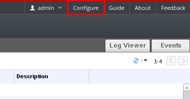
Figure 1.1. Accessing the Configure window
1.1. Roles
1.1.1. Creating a New Role
Procedure 1.1. Creating a New Role
- On the header bar, click the Configure button to open the Configure window. The window shows a list of default User and Administrator roles, and any custom roles.
- Click New. The New Role dialog box displays.

Figure 1.2. The New Role Dialog
- Enter the Name and Description of the new role.
- Select either Admin or User as the Account Type.
- Use the or buttons to view more or fewer of the permissions for the listed objects in the Check Boxes to Allow Action list. You can also expand or collapse the options for each object.
- For each of the objects, select or clear the actions you wish to permit or deny for the role you are setting up.
- Click to apply the changes you have made. The new role displays on the list of roles.
1.1.2. Editing or Copying a Role
Procedure 1.2. Editing or Copying a Role
- On the header bar, click the Configure button to open the Configure window. The window shows a list of default User and Administrator roles, and any custom roles.
- Select the role you wish to change. Click Edit to open the Edit Role window, or click Copy to open the Copy Role window.
- If necessary, edit the Name and Description of the role.
- Use the or buttons to view more or fewer of the permissions for the listed objects. You can also expand or collapse the options for each object.
- For each of the objects, select or clear the actions you wish to permit or deny for the role you are editing.
- Click to apply the changes you have made.
1.1.3. User Role and Authorization Examples
Example 1.1. Cluster Permissions
cluster called Accounts. She is assigned the ClusterAdmin role on the accounts cluster. This enables her to manage all virtual machines in the cluster, since the virtual machines are child objects of the cluster. Managing the virtual machines includes editing, adding, or removing virtual resources such as disks, and taking snapshots. It does not allow her to manage any resources outside this cluster. Because ClusterAdmin is an administrator role, it allows her to use the Administration Portal to manage these resources, but does not give her any access via the User Portal.
Example 1.2. VM PowerUser Permissions
johndesktop for him. John is assigned the UserVmManager role on the johndesktop virtual machine. This allows him to access this single virtual machine using the User Portal. Because he has UserVmManager permissions, he can modify the virtual machine and add resources to it, such as new virtual disks. Because UserVmManager is a user role, it does not allow him to use the Administration Portal.
Example 1.3. Data Center Power User Role Permissions
PowerUserRole permissions for the data center in which her new virtual machine will reside. This is because to create a new virtual machine, she needs to make changes to several components within the data center, including creating the virtual disk in the storage domain.
DataCenterAdmin privileges to Penelope. As a PowerUser for a data center, Penelope can log in to the User Portal and perform virtual machine-specific actions on virtual machines within the data center. She cannot perform data center-level operations such as attaching hosts or storage to a data center.
Example 1.4. Network Administrator Permissions
NetworkAdmin privileges on the IT department's data center, she can add and remove networks in the data center, and attach and detach networks for all virtual machines belonging to the data center.
VnicProfileUser permissions and UserVmManager permissions for the virtual machines used by the internal training department. With these permissions, Pat can perform simple administrative tasks such as adding network interfaces onto virtual machines in the Extended tab of the User Portal. However, he does not have permissions to alter the networks for the hosts on which the virtual machines run, or the networks on the data center to which the virtual machines belong.
Example 1.5. Custom Role Permissions
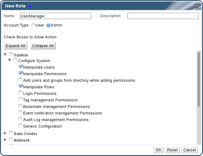
Figure 1.3. UserManager Custom Role
System - the top level object of the hierarchy shown in Figure 1.3, “UserManager Custom Role”. This means they apply to all other objects in the system. The role is set to have an Account Type of Admin. This means that when she is assigned this role, Rachel can only use the Administration Portal, not the User Portal.
1.2. System Permissions
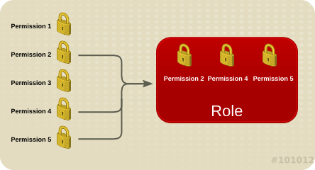
Figure 1.4. Permissions & Roles
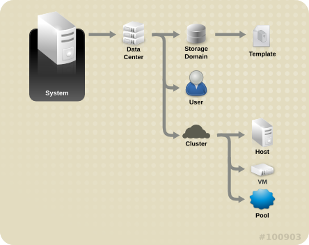
Figure 1.5. Red Hat Virtualization Object Hierarchy
1.2.1. User Properties
1.2.2. User and Administrator Roles
- Administrator Role: Allows access to the Administration Portal for managing physical and virtual resources. An administrator role confers permissions for actions to be performed in the User Portal; however, it has no bearing on what a user can see in the User Portal.
- User Role: Allows access to the User Portal for managing and accessing virtual machines and templates. A user role determines what a user can see in the User Portal. Permissions granted to a user with an administrator role are reflected in the actions available to that user in the User Portal.
administrator role on a cluster, you can manage all virtual machines in the cluster using the Administration Portal. However, you cannot access any of these virtual machines in the User Portal; this requires a user role.
1.2.3. User Roles Explained
| Role | Privileges | Notes |
|---|---|---|
| UserRole | Can access and use virtual machines and pools. | Can log in to the User Portal, use assigned virtual machines and pools, view virtual machine state and details. |
| PowerUserRole | Can create and manage virtual machines and templates. | Apply this role to a user for the whole environment with the Configure window, or for specific data centers or clusters. For example, if a PowerUserRole is applied on a data center level, the PowerUser can create virtual machines and templates in the data center. |
| UserVmManager | System administrator of a virtual machine. | Can manage virtual machines and create and use snapshots. A user who creates a virtual machine in the User Portal is automatically assigned the UserVmManager role on the machine. |
| Role | Privileges | Notes |
|---|---|---|
| UserTemplateBasedVm | Limited privileges to only use Templates. | Can use templates to create virtual machines. |
| DiskOperator | Virtual disk user. | Can use, view and edit virtual disks. Inherits permissions to use the virtual machine to which the virtual disk is attached. |
| VmCreator | Can create virtual machines in the User Portal. | This role is not applied to a specific virtual machine; apply this role to a user for the whole environment with the Configure window. Alternatively apply this role for specific data centers or clusters. When applying this role to a cluster, you must also apply the DiskCreator role on an entire data center, or on specific storage domains. |
| TemplateCreator | Can create, edit, manage and remove virtual machine templates within assigned resources. | This role is not applied to a specific template; apply this role to a user for the whole environment with the Configure window. Alternatively apply this role for specific data centers, clusters, or storage domains. |
| DiskCreator | Can create, edit, manage and remove virtual disks within assigned clusters or data centers. | This role is not applied to a specific virtual disk; apply this role to a user for the whole environment with the Configure window. Alternatively apply this role for specific data centers or storage domains. |
| TemplateOwner | Can edit and delete the template, assign and manage user permissions for the template. | This role is automatically assigned to the user who creates a template. Other users who do not have TemplateOwner permissions on a template cannot view or use the template. |
| VnicProfileUser | Logical network and network interface user for virtual machine and template. | Can attach or detach network interfaces from specific logical networks. |
1.2.4. Administrator Roles Explained
| Role | Privileges | Notes |
|---|---|---|
| SuperUser | System Administrator of the Red Hat Virtualization environment. | Has full permissions across all objects and levels, can manage all objects across all data centers. |
| ClusterAdmin | Cluster Administrator. | Possesses administrative permissions for all objects underneath a specific cluster. |
| DataCenterAdmin | Data Center Administrator. | Possesses administrative permissions for all objects underneath a specific data center except for storage. |
Important
| Role | Privileges | Notes |
|---|---|---|
| TemplateAdmin | Administrator of a virtual machine template. | Can create, delete, and configure the storage domains and network details of templates, and move templates between domains. |
| StorageAdmin | Storage Administrator. | Can create, delete, configure, and manage an assigned storage domain. |
| HostAdmin | Host Administrator. | Can attach, remove, configure, and manage a specific host. |
| NetworkAdmin | Network Administrator. | Can configure and manage the network of a particular data center or cluster. A network administrator of a data center or cluster inherits network permissions for virtual pools within the cluster. |
| VmPoolAdmin | System Administrator of a virtual pool. | Can create, delete, and configure a virtual pool; assign and remove virtual pool users; and perform basic operations on a virtual machine in the pool. |
| GlusterAdmin | Gluster Storage Administrator. | Can create, delete, configure, and manage Gluster storage volumes. |
| VmImporterExporter | Import and export Administrator of a virtual machine. | Can import and export virtual machines. Able to view all virtual machines and templates exported by other users. |
1.3. Scheduling Policies
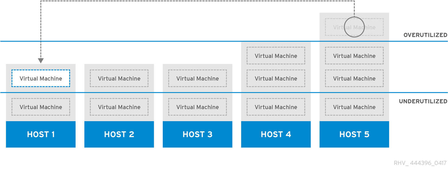
Figure 1.6. Evenly Distributed Scheduling Policy
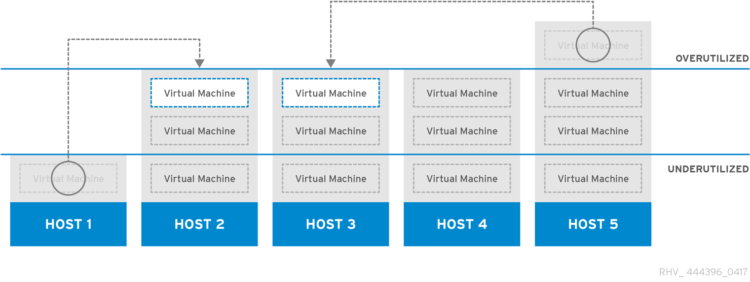
Figure 1.7. Power Saving Scheduling Policy
1.3.1. Creating a Scheduling Policy
Procedure 1.3. Creating a Scheduling Policy
- Click the button in the header bar of the Administration Portal to open the Configure window.
- Click Scheduling Policies to view the scheduling policies tab.
- Click to open the New Scheduling Policy window.
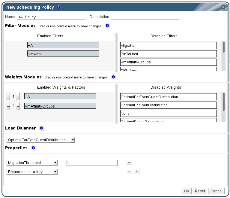
Figure 1.8. The New Scheduling Policy Window
- Enter a Name and Description for the scheduling policy.
- Configure filter modules:
- In the Filter Modules section, drag and drop the preferred filter modules to apply to the scheduling policy from the Disabled Filters section into the Enabled Filters section.
- Specific filter modules can also be set as the First, to be given highest priority, or Last, to be given lowest priority, for basic optimization.To set the priority, right-click any filter module, hover the cursor over Position and select First or Last.
- Configure weight modules:
- In the Weights Modules section, drag and drop the preferred weights modules to apply to the scheduling policy from the Disabled Weights section into the Enabled Weights & Factors section.
- Use the and buttons to the left of the enabled weight modules to increase or decrease the weight of those modules.
- Specify a load balancing policy:
- From the drop-down menu in the Load Balancer section, select the load balancing policy to apply to the scheduling policy.
- From the drop-down menu in the Properties section, select a load balancing property to apply to the scheduling policy and use the text field to the right of that property to specify a value.
- Use the and buttons to add or remove additional properties.
- Click .
1.3.2. Explanation of Settings in the New Scheduling Policy and Edit Scheduling Policy Window
|
Field Name
|
Description
|
|---|---|
|
Name
|
The name of the scheduling policy. This is the name used to refer to the scheduling policy in the Red Hat Virtualization Manager.
|
|
Description
|
A description of the scheduling policy. This field is recommended but not mandatory.
|
|
Filter Modules
|
A set of filters for controlling the hosts on which a virtual machine in a cluster can run. Enabling a filter will filter out hosts that do not meet the conditions specified by that filter, as outlined below:
|
|
Weights Modules
|
A set of weightings for controlling the relative priority of factors considered when determining the hosts in a cluster on which a virtual machine can run.
|
|
Load Balancer
|
This drop-down menu allows you to select a load balancing module to apply. Load balancing modules determine the logic used to migrate virtual machines from hosts experiencing high usage to hosts experiencing lower usage.
|
|
Properties
|
This drop-down menu allows you to add or remove properties for load balancing modules, and is only available when you have selected a load balancing module for the scheduling policy. No properties are defined by default, and the properties that are available are specific to the load balancing module that is selected. Use the and buttons to add or remove additional properties to or from the load balancing module.
|
1.4. Instance Types
|
Name
|
Memory
|
vCPUs
|
|---|---|---|
|
Tiny
|
512 MB
|
1
|
|
Small
|
2 GB
|
1
|
|
Medium
|
4 GB
|
2
|
|
Large
|
8 GB
|
2
|
|
XLarge
|
16 GB
|
4
|
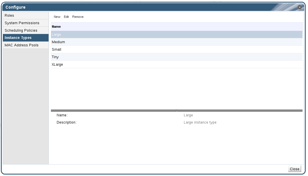
Figure 1.9. The Instance Types Tab
 ). If the value of one of these fields is changed, the virtual machine will be detached from the instance type, changing to Custom, and the chain will appear broken (
 ). However, if the value is changed back, the chain will relink and the instance type will move back to the selected one.
1.4.1. Creating Instance Types
Procedure 1.4. Creating an Instance Type
- On the header bar, click Configure.
- Click the Instance Types tab.
- Click to open the New Instance Type window.

Figure 1.10. The New Instance Type Window
- Enter a Name and Description for the instance type.
- Click and configure the instance type's settings as required. The settings that appear in the New Instance Type window are identical to those in the New Virtual Machine window, but with the relevant fields only. See Explanation of Settings in the New Virtual Machine and Edit Virtual Machine Windows in the Virtual Machine Management Guide.
- Click .
1.4.2. Editing Instance Types
Procedure 1.5. Editing Instance Type Properties
- On the header bar, click .
- Click the tab.
- Select the instance type to be edited.
- Click to open the Edit Instance Type window.
- Change the settings as required.
- Click .
1.4.3. Removing Instance Types
Procedure 1.6. Removing an Instance Type
- On the header bar, click .
- Click the tab.
- Select the instance type to be removed.
- Click to open the Remove Instance Type window.
- If any virtual machines are based on the instance type to be removed, a warning window listing the attached virtual machines will appear. To continue removing the instance type, select the Approve Operation checkbox. Otherwise click .
- Click .
1.5. MAC Address Pools
1.5.1. Creating MAC Address Pools
Procedure 1.7. Creating a MAC Address Pool
- On the header bar, click the Configure button to open the window.
- Click the MAC Address Pools tab.
- Click the button to open the New MAC Address Pool window.

Figure 1.11. The New MAC Address Pool Window
- Enter the Name and Description of the new MAC address pool.
- Select the Allow Duplicates check box to allow a MAC address to be used multiple times in a pool. The MAC address pool will not automatically use a duplicate MAC address, but enabling the duplicates option means a user can manually use a duplicate MAC address.
Note
If one MAC address pool has duplicates disabled, and another has duplicates enabled, each MAC address can be used once in the pool with duplicates disabled but can be used multiple times in the pool with duplicates enabled. - Enter the required MAC Address Ranges. To enter multiple ranges click the plus button next to the From and To fields.
- Click .
1.5.2. Editing MAC Address Pools
Procedure 1.8. Editing MAC Address Pool Properties
- On the header bar, click the Configure button to open the window.
- Click the MAC Address Pools tab.
- Select the MAC address pool to be edited.
- Click the button to open the Edit MAC Address Pool window.
- Change the Name, Description, Allow Duplicates, and MAC Address Ranges fields as required.
Note
When a MAC address range is updated, the MAC addresses of existing NICs are not reassigned. MAC addresses that were already assigned, but are outside of the new MAC address range, are added as user-specified MAC addresses and are still tracked by that MAC address pool. - Click .
1.5.3. Editing MAC Address Pool Permissions
Procedure 1.9. Editing MAC Address Pool Permissions
- On the header bar, click the Configure button to open the Configure window.
- Click the MAC Address Pools tab.
- Select the required MAC address pool.
- Edit the user permissions for the MAC address pool:
- To add user permissions to a MAC address pool:
- Click Add in the user permissions pane at the bottom of the Configure window.
- Search for and select the required users.
- Select the required role from the Role to Assign drop-down list.
- Click OK to add the user permissions.
- To remove user permissions from a MAC address pool:
- Select the user permission to be removed in the user permissions pane at the bottom of the Configure window.
- Click Remove to remove the user permissions.
1.5.4. Removing MAC Address Pools
Procedure 1.10. Removing a MAC Address Pool
- On the header bar, click the Configure button to open the window.
- Click the MAC Address Pools tab.
- Select the MAC address pool to be removed.
- Click the button to open the Remove MAC Address Pool window.
- Click .
Chapter 2. Dashboard
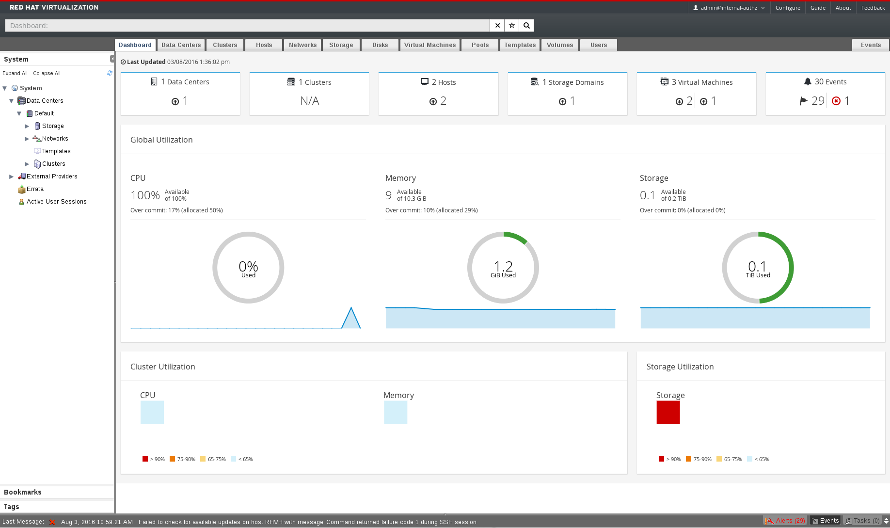
Figure 2.1. The Dashboard
2.1. Prerequisites
2.2. Global Inventory

Figure 2.2. Global Inventory
|
Icon
|
Status
|
|---|---|
 |
None of that resource added to Red Hat Virtualization.
|
 |
Shows the number of a resource with a warning status. Clicking on the icon navigates to the appropriate tab with the search limited to that resource with a warning status. The search is limited differently for each resource:
|
 |
Shows the number of a resource with an up status. Clicking on the icon navigates to the appropriate tab with the search limited to resources that are up.
|
 |
Shows the number of a resource with a down status. Clicking on the icon navigates to the appropriate tab with the search limited to resources with a down status. The search is limited differently for each resource:
|
 |
Shows the number of events with an alert status. Clicking on the icon navigates to the Events tab with the search limited to events with the severity of alert.
|
 |
Shows the number of events with an error status. Clicking on the icon navigates to the Events tab with the search limited to events with the severity of error.
|
2.3. Global Utilization
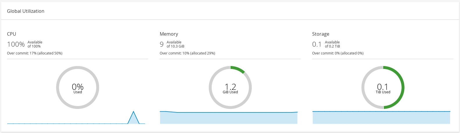
Figure 2.3. Global Utilization
- The top section shows the percentage of the available CPU, memory or storage and the over commit ratio. For example, the over commit ratio for the CPU is calculated by dividing the number of virtual cores by the number of physical cores that are available for the running virtual machines based on the latest data in the Data Warehouse.
- The donut displays the usage in percentage for the CPU, memory or storage and shows the average usage for all hosts based on the average usage in the last 5 minutes. Hovering over a section of the donut will display the value of the selected section.
- The line graph at the bottom displays the trend in the last 24 hours. Each data point shows the average usage for a specific hour. Hovering over a point on the graph displays the time and the percentage used for the CPU graph and the amount of usage for the memory and storage graphs.
2.3.1. Top Utilized Resources

Figure 2.4. Top Utilized Resources (Memory)
2.4. Cluster Utilization
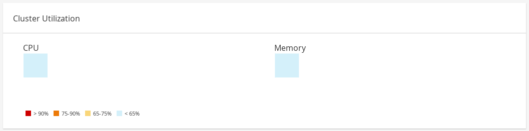
Figure 2.5. Cluster Utilization
2.4.1. CPU
2.4.2. Memory
2.5. Storage Utilization
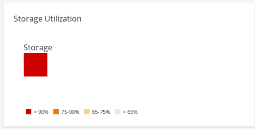
Figure 2.6. Storage Utilization
Part II. Administering the Resources
Chapter 3. Quality of Service
3.1. Storage Quality of Service
3.1.1. Creating a Storage Quality of Service Entry
Procedure 3.1. Creating a Storage Quality of Service Entry
- Click the Data Centers resource tab and select a data center.
- Click QoS in the details pane.
- Click Storage.
- Click .
- Enter a name for the quality of service entry in the QoS Name field.
- Enter a description for the quality of service entry in the Description field.
- Specify the throughput quality of service:
- Select the Throughput check box.
- Enter the maximum permitted total throughput in the Total field.
- Enter the maximum permitted throughput for read operations in the Read field.
- Enter the maximum permitted throughput for write operations in the Write field.
- Specify the input and output quality of service:
- Select the IOps check box.
- Enter the maximum permitted number of input and output operations per second in the Total field.
- Enter the maximum permitted number of input operations per second in the Read field.
- Enter the maximum permitted number of output operations per second in the Write field.
- Click .
3.1.2. Removing a Storage Quality of Service Entry
Procedure 3.2. Removing a Storage Quality of Service Entry
- Click the Data Centers resource tab and select a data center.
- Click QoS in the details pane.
- Click Storage.
- Select the storage quality of service entry to remove.
- Click .
- Click when prompted.
[unlimited].
3.2. Virtual Machine Network Quality of Service
3.2.1. Creating a Virtual Machine Network Quality of Service Entry
Procedure 3.3. Creating a Virtual Machine Network Quality of Service Entry
- Click the Data Centers resource tab and select a data center.
- Click the QoS tab in the details pane.
- Click .
- Click .
- Enter a name for the virtual machine network quality of service entry in the Name field.
- Enter the limits for the Inbound and Outbound network traffic.
- Click .
3.2.2. Settings in the New Virtual Machine Network QoS and Edit Virtual Machine Network QoS Windows Explained
|
Field Name
|
Description
|
|---|---|
|
Data Center
|
The data center to which the virtual machine network QoS policy is to be added. This field is configured automatically according to the selected data center.
|
|
Name
|
A name to represent the virtual machine network QoS policy within the Manager.
|
|
Inbound
|
The settings to be applied to inbound traffic. Select or clear the Inbound check box to enable or disable these settings.
|
|
Outbound
|
The settings to be applied to outbound traffic. Select or clear the Outbound check box to enable or disable these settings.
|
engine-config command to change the value of the MaxAverageNetworkQoSValue, MaxPeakNetworkQoSValue, or MaxBurstNetworkQoSValue configuration keys. You must restart the ovirt-engine service for any changes to take effect. For example:
# engine-config -s MaxAverageNetworkQoSValue=2048
# systemctl restart ovirt-engine
3.2.3. Removing a Virtual Machine Network Quality of Service Entry
Procedure 3.4. Removing a Virtual Machine Network Quality of Service Entry
- Click the Data Centers resource tab and select a data center.
- Click the QoS tab in the details pane.
- Click VM Network.
- Select the virtual machine network quality of service entry to remove.
- Click .
- Click when prompted.
3.3. Host Network Quality of Service
3.3.1. Creating a Host Network Quality of Service Entry
Procedure 3.5. Creating a Host Network Quality of Service Entry
- Click the Data Centers resource tab and select a data center.
- Click QoS in the details pane.
- Click Host Network.
- Click .
- Enter a name for the quality of service entry in the QoS Name field.
- Enter a description for the quality of service entry in the Description field.
- Enter the desired values for Weighted Share, Rate Limit [Mbps], and Committed Rate [Mbps].
- Click .
3.3.2. Settings in the New Host Network Quality of Service and Edit Host Network Quality of Service Windows Explained
|
Field Name
|
Description
|
|---|---|
|
Data Center
|
The data center to which the host network QoS policy is to be added. This field is configured automatically according to the selected data center.
|
|
QoS Name
|
A name to represent the host network QoS policy within the Manager.
|
|
Description
|
A description of the host network QoS policy.
|
|
Outbound
|
The settings to be applied to outbound traffic.
|
engine-config command to change the value of the MaxAverageNetworkQoSValue configuration key. You must restart the ovirt-engine service for the change to take effect. For example:
# engine-config -s MaxAverageNetworkQoSValue=2048
# systemctl restart ovirt-engine
3.3.3. Removing a Host Network Quality of Service Entry
Procedure 3.6. Removing a Host Network Quality of Service Entry
- Click the Data Centers resource tab and select a data center.
- Click the QoS tab in the details pane.
- Click Host Network.
- Select the network quality of service entry to remove.
- Click .
- Click when prompted.
3.4. CPU Quality of Service
3.4.1. Creating a CPU Quality of Service Entry
Procedure 3.7. Creating a CPU Quality of Service Entry
- Click the Data Centers resource tab and select a data center.
- Click QoS in the details pane.
- Click CPU.
- Click .
- Enter a name for the quality of service entry in the QoS Name field.
- Enter a description for the quality of service entry in the Description field.
- Enter the maximum processing capability the quality of service entry permits in the Limit field, in percentage. Do not include the
%symbol. - Click .
3.4.2. Removing a CPU Quality of Service Entry
Procedure 3.8. Removing a CPU Quality of Service Entry
- Click the Data Centers resource tab and select a data center.
- Click QoS in the details pane.
- Click CPU.
- Select the CPU quality of service entry to remove.
- Click .
- Click when prompted.
[unlimited].
Chapter 4. Data Centers
4.1. Introduction to Data Centers
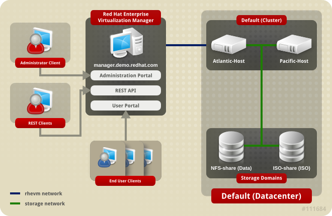
Figure 4.1. Data Centers
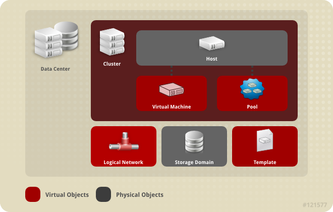
Figure 4.2. Data Center Objects
4.2. The Storage Pool Manager
4.3. SPM Priority
4.4. Using the Events Tab to Identify Problem Objects in Data Centers
4.5. Data Center Tasks
4.5.1. Creating a New Data Center
Note
Procedure 4.1. Creating a New Data Center
- Select the Data Centers resource tab to list all data centers in the results list.
- Click to open the New Data Center window.
- Enter the Name and Description of the data center.
- Select the Storage Type, Compatibility Version, and Quota Mode of the data center from the drop-down menus.
- Click to create the data center and open the New Data Center - Guide Me window.
- The Guide Me window lists the entities that need to be configured for the data center. Configure these entities or postpone configuration by clicking the button; configuration can be resumed by selecting the data center and clicking the button.
4.5.2. Explanation of Settings in the New Data Center and Edit Data Center Windows
|
Field
|
Description/Action
|
|---|---|
|
Name
|
The name of the data center. This text field has a 40-character limit and must be a unique name with any combination of uppercase and lowercase letters, numbers, hyphens, and underscores.
|
|
Description
| The description of the data center. This field is recommended but not mandatory. |
|
Type
|
The storage type. Choose one of the following:
Different types of storage domains (iSCSI, NFS, FC, POSIX, and Gluster) can be added to the same data center. Local and shared domains, however, cannot be mixed.
You can change the storage type after the data center is initialized. See Section 4.5.6, “Changing the Data Center Storage Type”.
|
|
Compatibility Version
|
The version of Red Hat Virtualization. Choose one of the following:
|
|
Quota Mode
| Quota is a resource limitation tool provided with Red Hat Virtualization. Choose one of:
|
4.5.3. Re-Initializing a Data Center: Recovery Procedure
Procedure 4.2. Re-Initializing a Data Center
- Click the Data Centers resource tab and select the data center to re-initialize.
- Ensure that any storage domains attached to the data center are in maintenance mode.
- Right-click the data center and select Re-Initialize Data Center from the drop-down menu to open the Data Center Re-Initialize window.
- The Data Center Re-Initialize window lists all available (detached; in maintenance mode) storage domains. Click the radio button for the storage domain you are adding to the data center.
- Select the Approve operation check box.
- Click to close the window and re-initialize the data center.
4.5.4. Removing a Data Center
Procedure 4.3. Removing a Data Center
- Ensure the storage domains attached to the data center is in maintenance mode.
- Click the Data Centers resource tab and select the data center to remove.
- Click to open the Remove Data Center(s) confirmation window.
- Click .
4.5.5. Force Removing a Data Center
Non Responsive if the attached storage domain is corrupt or if the host becomes Non Responsive. You cannot Remove the data center under either circumstance.
Procedure 4.4. Force Removing a Data Center
- Click the Data Centers resource tab and select the data center to remove.
- Click Force Remove to open the Force Remove Data Center confirmation window.
- Select the Approve operation check box.
- Click OK
4.5.6. Changing the Data Center Storage Type
Limitations
- Shared to Local - For a data center that does not contain more than one host and more than one cluster, since a local data center does not support it.
- Local to Shared - For a data center that does not contain a local storage domain.
Procedure 4.5. Changing the Data Center Storage Type
- From the Administration Portal, click the Data Centers tab.
- Select the data center to change from the list displayed.
- Click .
- Change the Storage to the desired value.
- Click .
4.5.7. Changing the Data Center Compatibility Version
Note
Procedure 4.6. Changing the Data Center Compatibility Version
- From the Administration Portal, click the Data Centers tab.
- Select the data center to change from the list displayed.
- Click .
- Change the Compatibility Version to the desired value.
- Click to open the Change Data Center Compatibility Version confirmation window.
- Click to confirm.
Important
4.6. Data Centers and Storage Domains
4.6.1. Attaching an Existing Data Domain to a Data Center
Procedure 4.7. Attaching an Existing Data Domain to a Data Center
- Click the Data Centers resource tab and select the appropriate data center.
- Select the Storage tab in the details pane to list the storage domains already attached to the data center.
- Click to open the Attach Storage window.
- Select the check box for the data domain to attach to the data center. You can select multiple check boxes to attach multiple data domains.
- Click .
4.6.2. Attaching an Existing ISO domain to a Data Center
Procedure 4.8. Attaching an Existing ISO Domain to a Data Center
- Click the Data Centers resource tab and select the appropriate data center.
- Select the Storage tab in the details pane to list the storage domains already attached to the data center.
- Click to open the Attach ISO Library window.
- Click the radio button for the appropriate ISO domain.
- Click .
4.6.3. Attaching an Existing Export Domain to a Data Center
Note
Procedure 4.9. Attaching an Existing Export Domain to a Data Center
- Click the Data Centers resource tab and select the appropriate data center.
- Select the Storage tab in the details pane to list the storage domains already attached to the data center.
- Click to open the Attach Export Domain window.
- Click the radio button for the appropriate Export domain.
- Click .
4.6.4. Detaching a Storage Domain from a Data Center
Note
Procedure 4.10. Detaching a Storage Domain from a Data Center
- Click the Data Centers resource tab and select the appropriate data center.
- Select the Storage tab in the details pane to list the storage domains attached to the data center.
- Select the storage domain to detach. If the storage domain is
Active, click to open the Maintenance Storage Domain(s) confirmation window. - Click to initiate maintenance mode.
- Click to open the Detach Storage confirmation window.
- Click .
4.7. Data Centers and Permissions
4.7.1. Managing System Permissions for a Data Center
- Create and remove clusters associated with the data center.
- Add and remove hosts, virtual machines, and pools associated with the data center.
- Edit user permissions for virtual machines associated with the data center.
Note
4.7.2. Data Center Administrator Roles Explained
The table below describes the administrator roles and privileges applicable to data center administration.
| Role | Privileges | Notes |
|---|---|---|
| DataCenterAdmin | Data Center Administrator | Can use, create, delete, manage all physical and virtual resources within a specific data center except for storage, including clusters, hosts, templates and virtual machines. |
| NetworkAdmin | Network Administrator | Can configure and manage the network of a particular data center. A network administrator of a data center inherits network permissions for virtual machines within the data center as well. |
4.7.3. Assigning an Administrator or User Role to a Resource
Procedure 4.11. Assigning a Role to a Resource
- Use the resource tabs, tree mode, or the search function to find and select the resource in the results list.
- Click the tab in the details pane to list the assigned users, the user's role, and the inherited permissions for the selected resource.
- Click .
- Enter the name or user name of an existing user into the Search text box and click . Select a user from the resulting list of possible matches.
- Select a role from the Role to Assign: drop-down list.
- Click .
4.7.4. Removing an Administrator or User Role from a Resource
Procedure 4.12. Removing a Role from a Resource
- Use the resource tabs, tree mode, or the search function to find and select the resource in the results list.
- Click the tab in the details pane to list the assigned users, the user's role, and the inherited permissions for the selected resource.
- Select the user to remove from the resource.
- Click . The Remove Permission window opens to confirm permissions removal.
- Click .
Chapter 5. Clusters
5.1. Introduction to Clusters
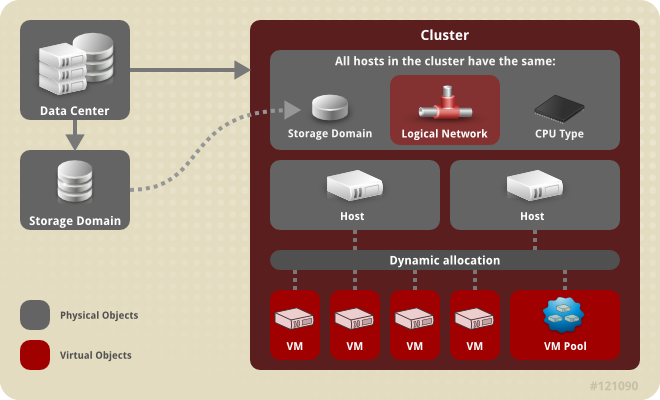
Figure 5.1. Cluster
5.2. Cluster Tasks
5.2.1. Creating a New Cluster
Procedure 5.1. Creating a New Cluster
- Select the Clusters resource tab.
- Click .
- Select the Data Center the cluster will belong to from the drop-down list.
- Enter the Name and Description of the cluster.
- Select a network from the Management Network drop-down list to assign the management network role.
- Select the CPU Architecture and CPU Type from the drop-down lists. It is important to match the CPU processor family with the minimum CPU processor type of the hosts you intend to attach to the cluster, otherwise the host will be non-operational.
Note
For both Intel and AMD CPU types, the listed CPU models are in logical order from the oldest to the newest. If your cluster includes hosts with different CPU models, select the oldest CPU model. For more information on each CPU model, see https://access.redhat.com/solutions/634853. - Select the Compatibility Version of the cluster from the drop-down list.
- Select either the Enable Virt Service or Enable Gluster Service radio button to define whether the cluster will be populated with virtual machine hosts or with Gluster-enabled nodes.
- Optionally select the Enable to set VM maintenance reason check box to enable an optional reason field when a virtual machine is shut down from the Manager, allowing the administrator to provide an explanation for the maintenance.
- Optionally select the Enable to set Host maintenance reason check box to enable an optional reason field when a host is placed into maintenance mode from the Manager, allowing the administrator to provide an explanation for the maintenance.
- Optionally select the /dev/hwrng source (external hardware device) check box to specify the random number generator device that all hosts in the cluster will use. The /dev/urandom source (Linux-provided device) is enabled by default.
- Click the Optimization tab to select the memory page sharing threshold for the cluster, and optionally enable CPU thread handling and memory ballooning on the hosts in the cluster.
- Click the Migration Policy tab to define the virtual machine migration policy for the cluster.
- Click the Scheduling Policy tab to optionally configure a scheduling policy, configure scheduler optimization settings, enable trusted service for hosts in the cluster, enable HA Reservation, and add a custom serial number policy.
- Click the Console tab to optionally override the global SPICE proxy, if any, and specify the address of a SPICE proxy for hosts in the cluster.
- Click the Fencing policy tab to enable or disable fencing in the cluster, and select fencing options.
- Click the MAC Address Pool tab to specify a MAC address pool other than the default pool for the cluster. For more options on creating, editing, or removing MAC address pools, see Section 1.5, “MAC Address Pools”.
- Click to create the cluster and open the New Cluster - Guide Me window.
- The Guide Me window lists the entities that need to be configured for the cluster. Configure these entities or postpone configuration by clicking the button; configuration can be resumed by selecting the cluster and clicking the button.
5.2.2. Explanation of Settings and Controls in the New Cluster and Edit Cluster Windows
5.2.2.1. General Cluster Settings Explained
|
Field
|
Description/Action
|
|---|---|
|
Data Center
|
The data center that will contain the cluster. The data center must be created before adding a cluster.
|
|
Name
|
The name of the cluster. This text field has a 40-character limit and must be a unique name with any combination of uppercase and lowercase letters, numbers, hyphens, and underscores.
|
|
Description / Comment
| The description of the cluster or additional notes. These fields are recommended but not mandatory. |
|
Management Network
|
The logical network which will be assigned the management network role. The default is ovirtmgmt. On existing clusters, the management network can only be changed via the button in the Logical Networks tab in the details pane.
|
| CPU Architecture | The CPU architecture of the cluster. Different CPU types are available depending on which CPU architecture is selected.
|
|
CPU Type
| The CPU type of the cluster. See CPU Requirements in the Planning and Prerequisites Guide for a list of supported CPU types. All hosts in a cluster must run either Intel, AMD, or IBM POWER 8 CPU type; this cannot be changed after creation without significant disruption. The CPU type should be set to the oldest CPU model in the cluster. Only features present in all models can be used. For both Intel and AMD CPU types, the listed CPU models are in logical order from the oldest to the newest. |
|
Compatibility Version
| The version of Red Hat Virtualization. Choose one of:
|
|
Enable Virt Service
| If this radio button is selected, hosts in this cluster will be used to run virtual machines. |
|
Enable Gluster Service
| If this radio button is selected, hosts in this cluster will be used as Red Hat Gluster Storage Server nodes, and not for running virtual machines. |
|
Import existing gluster configuration
|
This check box is only available if the Enable Gluster Service radio button is selected. This option allows you to import an existing Gluster-enabled cluster and all its attached hosts to Red Hat Virtualization Manager.
The following options are required for each host in the cluster that is being imported:
|
| Enable to set VM maintenance reason | If this check box is selected, an optional reason field will appear when a virtual machine in the cluster is shut down from the Manager. This allows you to provide an explanation for the maintenance, which will appear in the logs and when the virtual machine is powered on again. |
| Enable to set Host maintenance reason | If this check box is selected, an optional reason field will appear when a host in the cluster is moved into maintenance mode from the Manager. This allows you to provide an explanation for the maintenance, which will appear in the logs and when the host is activated again. |
| Additional Random Number Generator source |
If the check box is selected, all hosts in the cluster have the additional random number generator device available. This enables passthrough of entropy from the random number generator device to virtual machines.
|
5.2.2.2. Optimization Settings Explained
|
Field
|
Description/Action
|
|---|---|
|
Memory Optimization
|
|
|
CPU Threads
|
Selecting the Count Threads As Cores check box allows hosts to run virtual machines with a total number of processor cores greater than the number of cores in the host.
The exposed host threads would be treated as cores which can be utilized by virtual machines. For example, a 24-core system with 2 threads per core (48 threads total) can run virtual machines with up to 48 cores each, and the algorithms to calculate host CPU load would compare load against twice as many potential utilized cores.
|
|
Memory Balloon
|
Selecting the Enable Memory Balloon Optimization check box enables memory overcommitment on virtual machines running on the hosts in this cluster. When this option is set, the Memory Overcommit Manager (MoM) will start ballooning where and when possible, with a limitation of the guaranteed memory size of every virtual machine.
To have a balloon running, the virtual machine needs to have a balloon device with relevant drivers. Each virtual machine includes a balloon device unless specifically removed. Each host in this cluster receives a balloon policy update when its status changes to
Up. If necessary, you can manually update the balloon policy on a host without having to change the status. See Section 5.2.5, “Updating the MoM Policy on Hosts in a Cluster”.
It is important to understand that in some scenarios ballooning may collide with KSM. In such cases MoM will try to adjust the balloon size to minimize collisions. Additionally, in some scenarios ballooning may cause sub-optimal performance for a virtual machine. Administrators are advised to use ballooning optimization with caution.
|
|
KSM control
|
Selecting the Enable KSM check box enables MoM to run Kernel Same-page Merging (KSM) when necessary and when it can yield a memory saving benefit that outweighs its CPU cost.
|
5.2.2.3. Migration Policy Settings Explained
|
Policy
|
Description
|
|---|---|
|
Legacy
|
Legacy behavior of 3.6 version. Overrides in
vdsm.conf are still applied. The guest agent hook mechanism is disabled.
|
|
Minimal downtime
|
A policy that lets virtual machines migrate in typical situations. Virtual machines should not experience any significant downtime. The migration will be aborted if the virtual machine migration does not converge after a long time (dependent on QEMU iterations, with a maximum of 500 milliseconds). The guest agent hook mechanism is enabled.
|
|
Post-copy migration
|
This is a Technology Preview feature. Virtual machines should not experience any significant downtime similar to the minimal downtime policy. The migration will switch to post-copy if the virtual machine migration does not converge after a long time. The disadvantage of this policy is that in the post-copy phase, the virtual machine may slow down significantly as the missing parts of memory are transferred between the hosts. If anything goes wrong during the post-copy phase, such as a network failure between the hosts, then the running virtual machine instance will be lost. It is therefore not possible to abort a migration during the post-copy phase. The guest agent hook mechanism is enabled.
|
|
Suspend workload if needed
|
A policy that lets virtual machines migrate in most situations, including virtual machines running heavy workloads. Virtual machines may experience a more significant downtime. The migration may still be aborted for extreme workloads. The guest agent hook mechanism is enabled.
|
|
Policy
|
Description
|
|---|---|
|
Auto
|
Bandwidth is copied from the Rate Limit [Mbps] setting in the data center Host Network QoS. If the rate limit has not been defined, it is computed as a minimum of link speeds of sending and receiving network interfaces. If rate limit has not been set, and link speeds are not available, it is determined by local VDSM setting on sending host.
|
|
Hypervisor default
|
Bandwidth is controlled by local VDSM setting on sending Host.
|
|
Custom
|
Defined by user (in Mbps). This value is divided by the number of concurrent migrations (default is 2, to account for ingoing and outgoing migration). Therefore, the user-defined bandwidth must be large enough to accommodate all concurrent migrations.
For example, if the
Custom bandwidth is defined as 600 Mbps, a virtual machine migration's maximum bandwidth is actually 300 Mbps.
|
|
Field
|
Description/Action
|
|---|---|
|
Migrate Virtual Machines
|
Migrates all virtual machines in order of their defined priority.
|
|
Migrate only Highly Available Virtual Machines
|
Migrates only highly available virtual machines to prevent overloading other hosts.
|
|
Do Not Migrate Virtual Machines
| Prevents virtual machines from being migrated. |
|
Property
|
Description
|
|---|---|
|
Auto Converge migrations
|
Allows you to set whether auto-convergence is used during live migration of virtual machines. Large virtual machines with high workloads can dirty memory more quickly than the transfer rate achieved during live migration, and prevent the migration from converging. Auto-convergence capabilities in QEMU allow you to force convergence of virtual machine migrations. QEMU automatically detects a lack of convergence and triggers a throttle-down of the vCPUs on the virtual machine. Auto-convergence is disabled globally by default.
|
|
Enable migration compression
|
The option allows you to set whether migration compression is used during live migration of the virtual machine. This feature uses Xor Binary Zero Run-Length-Encoding to reduce virtual machine downtime and total live migration time for virtual machines running memory write-intensive workloads or for any application with a sparse memory update pattern. Migration compression is disabled globally by default.
|
5.2.2.4. Scheduling Policy Settings Explained
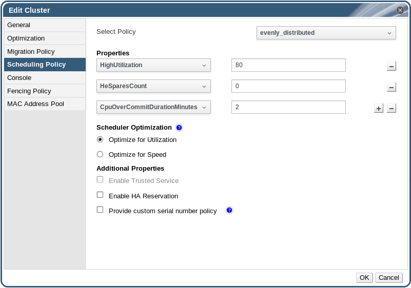
Figure 5.2. Scheduling Policy Settings: evenly_distributed
|
Field
|
Description/Action
|
|---|---|
|
Select Policy
|
Select a policy from the drop-down list.
|
|
Properties
|
The following properties appear depending on the selected policy, and can be edited if necessary:
|
|
Scheduler Optimization
|
Optimize scheduling for host weighing/ordering.
|
|
Enable Trusted Service
|
Enable integration with an OpenAttestation server. Before this can be enabled, use the
engine-config tool to enter the OpenAttestation server's details. For more information, see Section 10.4, “Trusted Compute Pools”.
|
|
Enable HA Reservation
|
Enable the Manager to monitor cluster capacity for highly available virtual machines. The Manager ensures that appropriate capacity exists within a cluster for virtual machines designated as highly available to migrate in the event that their existing host fails unexpectedly.
|
|
Provide custom serial number policy
|
This check box allows you to specify a serial number policy for the virtual machines in the cluster. Select one of the following options:
|
mom.Controllers.Balloon - INFO Ballooning guest:half1 from 1096400 to 1991580 are logged to /var/log/vdsm/mom.log. /var/log/vdsm/mom.log is the Memory Overcommit Manager log file.
5.2.2.5. Cluster Console Settings Explained
|
Field
|
Description/Action
|
|---|---|
|
Define SPICE Proxy for Cluster
|
Select this check box to enable overriding the SPICE proxy defined in global configuration. This feature is useful in a case where the user (who is, for example, connecting via the User Portal) is outside of the network where the hypervisors reside.
|
|
Overridden SPICE proxy address
|
The proxy by which the SPICE client will connect to virtual machines. The address must be in the following format:
protocol://[host]:[port] |
5.2.2.6. Fencing Policy Settings Explained
| Field | Description/Action |
|---|---|
| Enable fencing | Enables fencing on the cluster. Fencing is enabled by default, but can be disabled if required; for example, if temporary network issues are occurring or expected, administrators can disable fencing until diagnostics or maintenance activities are completed. Note that if fencing is disabled, highly available virtual machines running on non-responsive hosts will not be restarted elsewhere. |
| Skip fencing if host has live lease on storage | If this check box is selected, any hosts in the cluster that are Non Responsive and still connected to storage will not be fenced. |
| Skip fencing on cluster connectivity issues | If this check box is selected, fencing will be temporarily disabled if the percentage of hosts in the cluster that are experiencing connectivity issues is greater than or equal to the defined Threshold. The Threshold value is selected from the drop-down list; available values are 25, 50, 75, and 100. |
| Skip fencing if gluster bricks are up | This option is only available when Red Hat Gluster Storage functionality is enabled. If this check box is selected, fencing is skipped if bricks are running and can be reached from other peers. See Chapter 2. Configure High Availability using Fencing Policies and Appendix A. Fencing Policies for Red Hat Gluster Storage in Maintaining Red Hat Hyperconverged Infrastructure for more information. |
| Skip fencing if gluster quorum not met | This option is only available when Red Hat Gluster Storage functionality is enabled. If this check box is selected, fencing is skipped if bricks are running and shutting down the host will cause loss of quorum. See Chapter 2. Configure High Availability using Fencing Policies and Appendix A. Fencing Policies for Red Hat Gluster Storage in Maintaining Red Hat Hyperconverged Infrastructure for more information. |
5.2.3. Editing a Resource
Edit the properties of a resource.
Procedure 5.2. Editing a Resource
- Use the resource tabs, tree mode, or the search function to find and select the resource in the results list.
- Click to open the Edit window.
- Change the necessary properties and click .
The new properties are saved to the resource. The Edit window will not close if a property field is invalid.
5.2.4. Setting Load and Power Management Policies for Hosts in a Cluster
Procedure 5.3. Setting Load and Power Management Policies for Hosts
- Use the resource tabs, tree mode, or the search function to find and select the cluster in the results list.
- Click to open the Edit Cluster window.
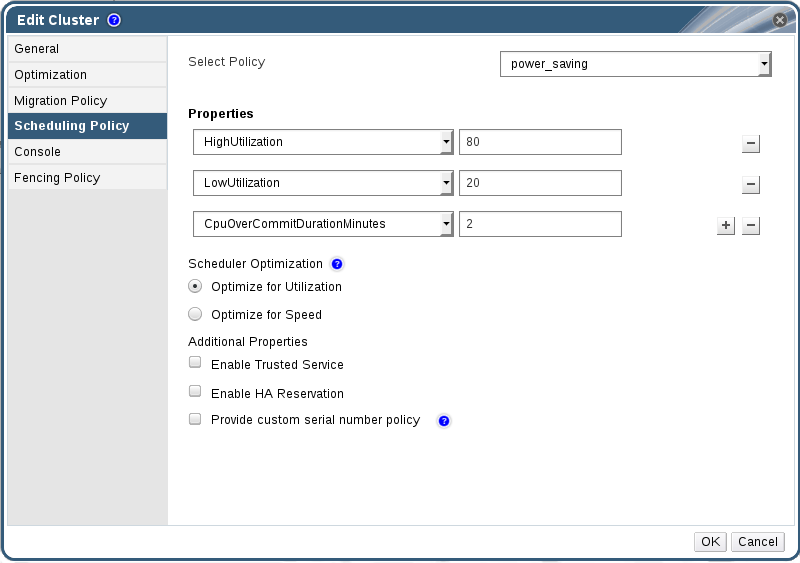
Figure 5.3. Edit Scheduling Policy
- Select one of the following policies:
- none
- vm_evenly_distributed
- Set the minimum number of virtual machines that must be running on at least one host to enable load balancing in the HighVmCount field.
- Define the maximum acceptable difference between the number of virtual machines on the most highly-utilized host and the number of virtual machines on the least-utilized host in the MigrationThreshold field.
- Define the number of slots for virtual machines to be reserved on SPM hosts in the SpmVmGrace field.
- Optionally, in the HeSparesCount field, enter the number of additional self-hosted engine nodes on which to reserve enough free memory to start the Manager virtual machine if it migrates or shuts down. See Configuring Memory Slots Reserved for the Self-Hosted Engine on Additional Hosts in the Self-Hosted Engine Guide for more information.
- evenly_distributed
- Set the time (in minutes) that a host can run a CPU load outside of the defined utilization values before the scheduling policy takes action in the CpuOverCommitDurationMinutes field.
- Enter the CPU utilization percentage at which virtual machines start migrating to other hosts in the HighUtilization field.
- Enter the minimum required free memory in MB above which virtual machines start migrating to other hosts in the MinFreeMemoryForUnderUtilized.
- Enter the maximum required free memory in MB below which virtual machines start migrating to other hosts in the MaxFreeMemoryForOverUtilized.
- Optionally, in the HeSparesCount field, enter the number of additional self-hosted engine nodes on which to reserve enough free memory to start the Manager virtual machine if it migrates or shuts down. See Configuring Memory Slots Reserved for the Self-Hosted Engine on Additional Hosts in the Self-Hosted Engine Guide for more information.
- power_saving
- Set the time (in minutes) that a host can run a CPU load outside of the defined utilization values before the scheduling policy takes action in the CpuOverCommitDurationMinutes field.
- Enter the CPU utilization percentage below which the host will be considered under-utilized in the LowUtilization field.
- Enter the CPU utilization percentage at which virtual machines start migrating to other hosts in the HighUtilization field.
- Enter the minimum required free memory in MB above which virtual machines start migrating to other hosts in the MinFreeMemoryForUnderUtilized.
- Enter the maximum required free memory in MB below which virtual machines start migrating to other hosts in the MaxFreeMemoryForOverUtilized.
- Optionally, in the HeSparesCount field, enter the number of additional self-hosted engine nodes on which to reserve enough free memory to start the Manager virtual machine if it migrates or shuts down. See Configuring Memory Slots Reserved for the Self-Hosted Engine on Additional Hosts in the Self-Hosted Engine Guide for more information.
- Choose one of the following as the Scheduler Optimization for the cluster:
- Select Optimize for Utilization to include weight modules in scheduling to allow best selection.
- Select Optimize for Speed to skip host weighting in cases where there are more than ten pending requests.
- If you are using an OpenAttestation server to verify your hosts, and have set up the server's details using the
engine-configtool, select the Enable Trusted Service check box. - Optionally select the Enable HA Reservation check box to enable the Manager to monitor cluster capacity for highly available virtual machines.
- Optionally select the Provide custom serial number policy check box to specify a serial number policy for the virtual machines in the cluster, and then select one of the following options:
- Select Host ID to set the host's UUID as the virtual machine's serial number.
- Select Vm ID to set the virtual machine's UUID as its serial number.
- Select Custom serial number, and then specify a custom serial number in the text field.
- Click .
5.2.5. Updating the MoM Policy on Hosts in a Cluster
Procedure 5.4. Synchronizing MoM Policy on a Host
- Click the Clusters tab and select the cluster to which the host belongs.
- Click the Hosts tab in the details pane and select the host that requires an updated MoM policy.
- Click .
5.2.6. CPU Profiles
5.2.6.1. Creating a CPU Profile
Procedure 5.5. Creating a CPU Profile
- Click the Clusters resource tab and select a cluster.
- Click the CPU Profiles sub tab in the details pane.
- Click .
- Enter a name for the CPU profile in the Name field.
- Enter a description for the CPU profile in the Description field.
- Select the quality of service to apply to the CPU profile from the QoS list.
- Click .
5.2.6.2. Removing a CPU Profile
Procedure 5.6. Removing a CPU Profile
- Click the Clusters resource tab and select a cluster.
- Click the CPU Profiles sub tab in the details pane.
- Select the CPU profile to remove.
- Click .
- Click .
default CPU profile.
5.2.7. Importing an Existing Red Hat Gluster Storage Cluster
gluster peer status command is executed on that host through SSH, then displays a list of hosts that are a part of the cluster. You must manually verify the fingerprint of each host and provide passwords for them. You will not be able to import the cluster if one of the hosts in the cluster is down or unreachable. As the newly imported hosts do not have VDSM installed, the bootstrap script installs all the necessary VDSM packages on the hosts after they have been imported, and reboots them.
Procedure 5.7. Importing an Existing Red Hat Gluster Storage Cluster to Red Hat Virtualization Manager
- Select the Clusters resource tab to list all clusters in the results list.
- Click to open the New Cluster window.
- Select the Data Center the cluster will belong to from the drop-down menu.
- Enter the Name and Description of the cluster.
- Select the Enable Gluster Service radio button and the Import existing gluster configuration check box.The Import existing gluster configuration field is displayed only if you select Enable Gluster Service radio button.
- In the Address field, enter the hostname or IP address of any server in the cluster.The host Fingerprint displays to ensure you are connecting with the correct host. If a host is unreachable or if there is a network error, an error Error in fetching fingerprint displays in the Fingerprint field.
- Enter the Root Password for the server, and click OK.
- The Add Hosts window opens, and a list of hosts that are a part of the cluster displays.
- For each host, enter the Name and the Root Password.
- If you wish to use the same password for all hosts, select the Use a Common Password check box to enter the password in the provided text field.Click to set the entered password all hosts.Make sure the fingerprints are valid and submit your changes by clicking .
5.2.8. Explanation of Settings in the Add Hosts Window
| Field | Description |
|---|---|
| Use a common password | Tick this check box to use the same password for all hosts belonging to the cluster. Enter the password in the Password field, then click the Apply button to set the password on all hosts. |
| Name | Enter the name of the host. |
| Hostname/IP | This field is automatically populated with the fully qualified domain name or IP of the host you provided in the New Cluster window. |
| Root Password | Enter a password in this field to use a different root password for each host. This field overrides the common password provided for all hosts in the cluster. |
| Fingerprint | The host fingerprint is displayed to ensure you are connecting with the correct host. This field is automatically populated with the fingerprint of the host you provided in the New Cluster window. |
5.2.9. Removing a Cluster
Move all hosts out of a cluster before removing it.
Note
Procedure 5.8. Removing a Cluster
- Use the resource tabs, tree mode, or the search function to find and select the cluster in the results list.
- Ensure there are no hosts in the cluster.
- Click to open the Remove Cluster(s) confirmation window.
- Click
The cluster is removed.
5.2.10. Changing the Cluster Compatibility Version
Note
Procedure 5.9. Changing the Cluster Compatibility Version
- From the Administration Portal, click the Clusters tab.
- Select the cluster to change from the list displayed.
- Click .
- Change the Compatibility Version to the desired value.
- Click to open the Change Cluster Compatibility Version confirmation window.
- Click to confirm.
Important
5.3. Clusters and Permissions
5.3.1. Managing System Permissions for a Cluster
- Create and remove associated clusters.
- Add and remove hosts, virtual machines, and pools associated with the cluster.
- Edit user permissions for virtual machines associated with the cluster.
Note
5.3.2. Cluster Administrator Roles Explained
The table below describes the administrator roles and privileges applicable to cluster administration.
| Role | Privileges | Notes |
|---|---|---|
| ClusterAdmin | Cluster Administrator |
Can use, create, delete, manage all physical and virtual resources in a specific cluster, including hosts, templates and virtual machines. Can configure network properties within the cluster such as designating display networks, or marking a network as required or non-required.
However, a ClusterAdmin does not have permissions to attach or detach networks from a cluster, to do so NetworkAdmin permissions are required.
|
| NetworkAdmin | Network Administrator | Can configure and manage the network of a particular cluster. A network administrator of a cluster inherits network permissions for virtual machines within the cluster as well. |
5.3.3. Assigning an Administrator or User Role to a Resource
Procedure 5.10. Assigning a Role to a Resource
- Use the resource tabs, tree mode, or the search function to find and select the resource in the results list.
- Click the tab in the details pane to list the assigned users, the user's role, and the inherited permissions for the selected resource.
- Click .
- Enter the name or user name of an existing user into the Search text box and click . Select a user from the resulting list of possible matches.
- Select a role from the Role to Assign: drop-down list.
- Click .
5.3.4. Removing an Administrator or User Role from a Resource
Procedure 5.11. Removing a Role from a Resource
- Use the resource tabs, tree mode, or the search function to find and select the resource in the results list.
- Click the tab in the details pane to list the assigned users, the user's role, and the inherited permissions for the selected resource.
- Select the user to remove from the resource.
- Click . The Remove Permission window opens to confirm permissions removal.
- Click .
Chapter 6. Logical Networks
6.1. Logical Network Tasks
6.1.1. Using the Networks Tab
- Attaching or detaching the networks to clusters and hosts
- Removing network interfaces from virtual machines and templates
- Adding and removing permissions for users to access and manage networks
Warning
Important
- Directory Services
- DNS
- Storage
6.1.2. Creating a New Logical Network in a Data Center or Cluster
Procedure 6.1. Creating a New Logical Network in a Data Center or Cluster
- Click the Data Centers or Clusters resource tabs, and select a data center or cluster in the results list.
- Click the Logical Networks tab of the details pane to list the existing logical networks.
- From the Data Centers details pane, click to open the New Logical Network window.
- From the Clusters details pane, click to open the New Logical Network window.
- Enter a Name, Description, and Comment for the logical network.
- Optionally select the Create on external provider check box. Select the External Provider from the drop-down list and provide the IP address of the Physical Network. The External Provider drop-down list will not list any external providers in read-only mode.If Create on external provider is selected, the Network Label, VM Network, and MTU options are disabled.
- Enter a new label or select an existing label for the logical network in the Network Label text field.
- Optionally enable Enable VLAN tagging.
- Optionally disable VM Network.
- Set the MTU value to Default (1500) or Custom.
- From the Cluster tab, select the clusters to which the network will be assigned. You can also specify whether the logical network will be a required network.
- If Create on external provider is selected, the Subnet tab will be visible. From the Subnet tab, select the Create subnet and enter a Name, CIDR, and Gateway address, and select an IP Version for the subnet that the logical network will provide. You can also add DNS servers as required.
- From the vNIC Profiles tab, add vNIC profiles to the logical network as required.
- Click OK.
Note
6.1.3. Editing a Logical Network
Procedure 6.2. Editing a Logical Network
Important
- Click the Data Centers resource tab, and select the data center of the logical network in the results list.
- Click the Logical Networks tab in the details pane to list the logical networks in the data center.
- Select a logical network and click to open the Edit Logical Network window.
- Edit the necessary settings.
Note
You can edit the name of a new or existing network, with the exception of the default network, without having to stop the virtual machines. - Click OK to save the changes.
Note
6.1.4. Removing a Logical Network
ovirtmgmt management network.
Procedure 6.3. Removing Logical Networks
- Click the Data Centers resource tab, and select the data center of the logical network in the results list.
- Click the Logical Networks tab in the details pane to list the logical networks in the data center.
- Select a logical network and click to open the Remove Logical Network(s) window.
- Optionally, select the Remove external network(s) from the provider(s) as well check box to remove the logical network both from the Manager and from the external provider if the network is provided by an external provider. The check box is grayed out if the external provider is in read-only mode.
- Click OK.
6.1.5. Viewing or Editing the Gateway for a Logical Network
Procedure 6.4. Viewing or Editing the Gateway for a Logical Network
- Click the Hosts resource tab, and select the desired host.
- Click the Network Interfaces tab in the details pane to list the network interfaces attached to the host and their configurations.
- Click the button to open the Setup Host Networks window.
- Hover your cursor over an assigned logical network and click the pencil icon to open the Edit Management Network window.
6.1.6. Explanation of Settings and Controls in the New Logical Network and Edit Logical Network Windows
6.1.6.1. Logical Network General Settings Explained
|
Field Name
|
Description
|
|---|---|
|
Name
|
The name of the logical network. This text field must be a unique name with any combination of uppercase and lowercase letters, numbers, hyphens, and underscores. The logical network name is limited to 15 characters for Manager version 4.1.5 and earlier.
|
|
Description
|
The description of the logical network. This text field has a 40-character limit.
|
|
Comment
|
A field for adding plain text, human-readable comments regarding the logical network.
|
|
Create on external provider
|
Allows you to create the logical network to an OpenStack Networking instance that has been added to the Manager as an external provider.
External Provider - Allows you to select the external provider on which the logical network will be created.
|
|
Enable VLAN tagging
|
VLAN tagging is a security feature that gives all network traffic carried on the logical network a special characteristic. VLAN-tagged traffic cannot be read by interfaces that do not also have that characteristic. Use of VLANs on logical networks also allows a single network interface to be associated with multiple, differently VLAN-tagged logical networks. Enter a numeric value in the text entry field if VLAN tagging is enabled.
|
|
VM Network
|
Select this option if only virtual machines use this network. If the network is used for traffic that does not involve virtual machines, such as storage communications, do not select this check box.
|
|
MTU
|
Choose either Default, which sets the maximum transmission unit (MTU) to the value given in the parenthesis (), or Custom to set a custom MTU for the logical network. You can use this to match the MTU supported by your new logical network to the MTU supported by the hardware it interfaces with. Enter a numeric value in the text entry field if Custom is selected.
|
|
Network Label
|
Allows you to specify a new label for the network or select from existing labels already attached to host network interfaces. If you select an existing label, the logical network will be automatically assigned to all host network interfaces with that label.
|
6.1.6.2. Logical Network Cluster Settings Explained
|
Field Name
|
Description
|
|---|---|
|
Attach/Detach Network to/from Cluster(s)
|
Allows you to attach or detach the logical network from clusters in the data center and specify whether the logical network will be a required network for individual clusters.
Name - the name of the cluster to which the settings will apply. This value cannot be edited.
Attach All - Allows you to attach or detach the logical network to or from all clusters in the data center. Alternatively, select or clear the Attach check box next to the name of each cluster to attach or detach the logical network to or from a given cluster.
Required All - Allows you to specify whether the logical network is a required network on all clusters. Alternatively, select or clear the Required check box next to the name of each cluster to specify whether the logical network is a required network for a given cluster.
|
6.1.6.3. Logical Network vNIC Profiles Settings Explained
|
Field Name
|
Description
|
|---|---|
|
vNIC Profiles
|
Allows you to specify one or more vNIC profiles for the logical network. You can add or remove a vNIC profile to or from the logical network by clicking the plus or minus button next to the vNIC profile. The first field is for entering a name for the vNIC profile.
Public - Allows you to specify whether the profile is available to all users.
QoS - Allows you to specify a network quality of service (QoS) profile to the vNIC profile.
|
6.1.7. Designate a Specific Traffic Type for a Logical Network with the Manage Networks Window
Procedure 6.5. Specifying Traffic Types for Logical Networks
- Click the Clusters resource tab, and select a cluster from the results list.
- Select the Logical Networks tab in the details pane to list the logical networks assigned to the cluster.
- Click to open the Manage Networks window.

Figure 6.1. Manage Networks
- Select appropriate check boxes.
- Click to save the changes and close the window.
Note
6.1.8. Explanation of Settings in the Manage Networks Window
|
Field
|
Description/Action
|
|---|---|
|
Assign
|
Assigns the logical network to all hosts in the cluster.
|
|
Required
|
A Network marked "required" must remain operational in order for the hosts associated with it to function properly. If a required network ceases to function, any hosts associated with it become non-operational.
|
|
VM Network
| A logical network marked "VM Network" carries network traffic relevant to the virtual machine network. |
|
Display Network
| A logical network marked "Display Network" carries network traffic relevant to SPICE and to the virtual network controller. |
|
Migration Network
| A logical network marked "Migration Network" carries virtual machine and storage migration traffic. |
6.1.9. Editing the Virtual Function Configuration on a NIC
Procedure 6.6. Editing the Virtual Function Configuration on a NIC
- Select an SR-IOV-capable host and click the Network Interfaces tab in the details pane.
- Click to open the Setup Host Networks window.
- Select an SR-IOV-capable NIC, marked with a
 , and click the pencil icon to open the Edit Virtual Functions (SR-IOV) configuration of NIC window.
- To edit the number of virtual functions, click the Number of VFs setting drop-down button and edit the Number of VFs text field.
Important
Changing the number of VFs will delete all previous VFs on the network interface before creating new VFs. This includes any VFs that have virtual machines directly attached. - The All Networks check box is selected by default, allowing all networks to access the virtual functions. To specify the virtual networks allowed to access the virtual functions, select the Specific networks radio button to list all networks. You can then either select the check box for desired networks, or you can use the Labels text field to automatically select networks based on one or more network labels.
- Click to close the window. Note that the configuration changes will not take effect until you click the button in the Setup Host Networks window.
6.2. Virtual Network Interface Cards
6.2.1. vNIC Profile Overview
6.2.2. Creating or Editing a vNIC Profile
Note
Procedure 6.7. Creating or Editing a vNIC Profile
- Click the Networks resource tab, and select a logical network in the results list.
- Select the vNIC Profiles tab in the details pane. If you selected the logical network in tree mode, you can select the vNIC Profiles tab in the results list.
- Click or to open the VM Interface Profile window.

Figure 6.2. The VM Interface Profile window
- Enter the Name and Description of the profile.
- Select the relevant Quality of Service policy from the QoS list.
- Select a Network Filter from the drop-down list to manage the traffic of network packets to and from virtual machines. For more information on network filters, see Applying network filtering in the Red Hat Enterprise Linux Virtualization Deployment and Administration Guide.
- Select the Passthrough check box to enable passthrough of the vNIC and allow direct device assignment of a virtual function. Enabling the passthrough property will disable QoS, network filtering, and port mirroring as these are not compatible. For more information on passthrough, see Section 6.2.4, “Enabling Passthrough on a vNIC Profile”.
- If Passthrough is selected, optionally deselect the Migratable check box to disable migration for vNICs using this profile. If you keep this check box selected, see Additional Prerequisites for Virtual Machines with SR-IOV-Enabled vNICs in the Virtual Machine Management Guide.
- Use the Port Mirroring and Allow all users to use this Profile check boxes to toggle these options.
- Select a custom property from the custom properties list, which displays Please select a key... by default. Use the and buttons to add or remove custom properties.
- Click .
Note
6.2.3. Explanation of Settings in the VM Interface Profile Window
|
Field Name
|
Description
|
|---|---|
|
Network
|
A drop-down list of the available networks to apply the vNIC profile to.
|
|
Name
|
The name of the vNIC profile. This must be a unique name with any combination of uppercase and lowercase letters, numbers, hyphens, and underscores between 1 and 50 characters.
|
| Description |
The description of the vNIC profile. This field is recommended but not mandatory.
|
| QoS |
A drop-down list of the available Network Quality of Service policies to apply to the vNIC profile. QoS policies regulate inbound and outbound network traffic of the vNIC.
|
| Network Filter |
A drop-down list of the available network filters to apply to the vNIC profile. Network filters improve network security by filtering the type of packets that can be sent to and from virtual machines. The default filter is
vdsm-no-mac-spoofing, which is a combination of no-mac-spoofing and no-arp-mac-spoofing. For more information on the network filters provided by libvirt, see the Pre-existing network filters section of the Red Hat Enterprise Linux Virtualization Deployment and Administration Guide.
<No Network Filter> should be used for virtual machine VLANs and bonds. On trusted virtual machines, choosing not to use a network filter can improve performance.
|
| Passthrough |
A check box to toggle the passthrough property. Passthrough allows a vNIC to connect directly to a virtual function of a host NIC. The passthrough property cannot be edited if the vNIC profile is attached to a virtual machine.
QoS, network filters, and port mirroring are disabled in the vNIC profile if passthrough is enabled.
|
| Migratable |
A check box to toggle whether or not vNICs using this profile can be migrated. Migration is enabled by default on regular vNIC profiles; the check box is selected and cannot be changed. When the Passthrough check box is selected, Migratable becomes available and can be deselected, if required, to disable migration of passthrough vNICs.
|
| Port Mirroring |
A check box to toggle port mirroring. Port mirroring copies layer 3 network traffic on the logical network to a virtual interface on a virtual machine. It it not selected by default. For further details, see Port Mirroring in the Technical Reference.
|
| Device Custom Properties |
A drop-down menu to select available custom properties to apply to the vNIC profile. Use the and buttons to add and remove properties respectively.
|
| Allow all users to use this Profile |
A check box to toggle the availability of the profile to all users in the environment. It is selected by default.
|
6.2.4. Enabling Passthrough on a vNIC Profile
Procedure 6.8. Enabling Passthrough
- Select a logical network from the Networks results list and click the vNIC Profiles tab in the details pane to list all vNIC profiles for that logical network.
- Click to open the VM Interface Profile window.
- Enter the Name and Description of the profile.
- Select the Passthrough check box.
- Optionally deselect the Migratable check box to disable migration for vNICs using this profile. If you keep this check box selected, see Additional Prerequisites for Virtual Machines with SR-IOV-Enabled vNICs in the Virtual Machine Management Guide.
- If necessary, select a custom property from the custom properties list, which displays Please select a key... by default. Use the and buttons to add or remove custom properties.
- Click to save the profile and close the window.
6.2.5. Removing a vNIC Profile
Procedure 6.9. Removing a vNIC Profile
- Click the Networks resource tab, and select a logical network in the results list.
- Select the Profiles tab in the details pane to display available vNIC profiles. If you selected the logical network in tree mode, you can select the VNIC Profiles tab in the results list.
- Select one or more profiles and click to open the Remove VM Interface Profile(s) window.
- Click to remove the profile and close the window.
6.2.6. Assigning Security Groups to vNIC Profiles
Note
Note
# neutron security-group-list
Procedure 6.10. Assigning Security Groups to vNIC Profiles
- Click the Networks tab and select a logical network from the results list.
- Click the vNIC Profiles tab in the details pane.
- Click , or select an existing vNIC profile and click , to open the VM Interface Profile window.
- From the custom properties drop-down list, select SecurityGroups. Leaving the custom property drop-down blank applies the default security settings, which permit all outbound traffic and intercommunication but deny all inbound traffic from outside of the default security group. Note that removing the SecurityGroups property later will not affect the applied security group.
- In the text field, enter the ID of the security group to attach to the vNIC profile.
- Click .
6.2.7. User Permissions for vNIC Profiles
Procedure 6.11. User Permissions for vNIC Profiles
- Click the Networks tab and select a logical network from the results list.
- Click the vNIC Profiles resource tab to display the vNIC profiles.
- Click the Permissions tab in the details pane to show the current user permissions for the profile.
- Click the button to open the Add Permission to User window, and the button to open the Remove Permission window, to change user permissions for the vNIC profile.
- In the Add Permissions to User window, click My Groups to display your user groups. You can use this option to grant permissions to other users in your groups.
6.2.8. Configuring vNIC Profiles for UCS Integration
vdsm-hook-vmfex-dev hook allows virtual machines to connect to Cisco's UCS-defined port profiles by configuring the vNIC profile. The UCS-defined port profiles contain the properties and settings used to configure virtual interfaces in UCS. The vdsm-hook-vmfex-dev hook is installed by default with VDSM. See Appendix A, VDSM and Hooks for more information.
Note
Procedure 6.12. Configuring the Custom Device Property
- On the Red Hat Virtualization Manager, configure the
vmfexcustom property and set the cluster compatibility level using--cver.# engine-config -s CustomDeviceProperties='{type=interface;prop={vmfex=^[a-zA-Z0-9_.-]{2,32}$}}' --cver=3.6 - Verify that the
vmfexcustom device property was added.# engine-config -g CustomDeviceProperties
- Restart the engine.
# systemctl restart ovirt-engine.service
Procedure 6.13. Configuring a vNIC Profile for UCS Integration
- Click the Networks resource tab, and select a logical network in the results list.
- Select the vNIC Profiles tab in the details pane. If you selected the logical network in tree mode, you can select the vNIC Profiles tab in the results list.
- Click or to open the VM Interface Profile window.
- Enter the Name and Description of the profile.
- Select the
vmfexcustom property from the custom properties list and enter the UCS port profile name. - Click .
6.3. External Provider Networks
6.3.1. Importing Networks From External Providers
Procedure 6.14. Importing a Network From an External Provider
- Click the Networks tab.
- Click the button to open the Import Networks window.
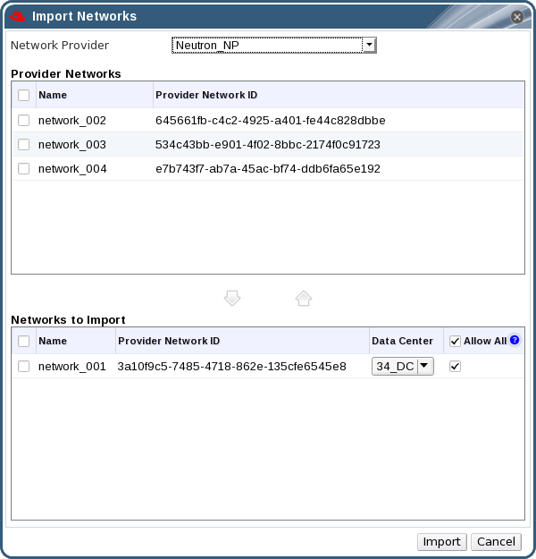
Figure 6.3. The Import Networks Window
- From the Network Provider drop-down list, select an external provider. The networks offered by that provider are automatically discovered and listed in the Provider Networks list.
- Using the check boxes, select the networks to import in the Provider Networks list and click the down arrow to move those networks into the Networks to Import list.
- It is possible to customize the name of the network that you are importing. To customize the name, click on the network's name in the Name column, and change the text.
- From the Data Center drop-down list, select the data center into which the networks will be imported.
- Optionally, clear the Allow All check box for a network in the Networks to Import list to prevent that network from being available to all users.
- Click the button.
6.3.2. Limitations to Using External Provider Networks
- Logical networks offered by external providers must be used as virtual machine networks, and cannot be used as display networks.
- The same logical network can be imported more than once, but only to different data centers.
- You cannot edit logical networks offered by external providers in the Manager. To edit the details of a logical network offered by an external provider, you must edit the logical network directly from the external provider that provides that logical network.
- Port mirroring is not available for virtual network interface cards connected to logical networks offered by external providers.
- If a virtual machine uses a logical network offered by an external provider, that provider cannot be deleted from the Manager while the logical network is still in use by the virtual machine.
- Networks offered by external providers are non-required. As such, scheduling for clusters in which such logical networks have been imported will not take those logical networks into account during host selection. Moreover, it is the responsibility of the user to ensure the availability of the logical network on hosts in clusters in which such logical networks have been imported.
6.3.3. Configuring Subnets on External Provider Logical Networks
6.3.3.1. Configuring Subnets on External Provider Logical Networks
6.3.3.2. Adding Subnets to External Provider Logical Networks
Procedure 6.15. Adding Subnets to External Provider Logical Networks
- Click the Networks tab.
- Click the logical network provided by an external provider to which the subnet will be added.
- Click the Subnets tab in the details pane.
- Click the button to open the New External Subnet window.
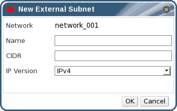
Figure 6.4. The New External Subnet Window
- Enter a Name and CIDR for the new subnet.
- From the IP Version drop-down menu, select either IPv4 or IPv6.
- Click .
6.3.3.3. Removing Subnets from External Provider Logical Networks
Procedure 6.16. Removing Subnets from External Provider Logical Networks
- Click the Networks tab.
- Click the logical network provided by an external provider from which the subnet will be removed.
- Click the Subnets tab in the details pane.
- Click the subnet to remove.
- Click the button and click when prompted.
6.4. Logical Networks and Permissions
6.4.1. Managing System Permissions for a Network
- Create, edit and remove networks.
- Edit the configuration of the network, including configuring port mirroring.
- Attach and detach networks from resources including clusters and virtual machines.
6.4.2. Network Administrator and User Roles Explained
The table below describes the administrator and user roles and privileges applicable to network administration.
| Role | Privileges | Notes |
|---|---|---|
| NetworkAdmin | Network Administrator for data center, cluster, host, virtual machine, or template. The user who creates a network is automatically assigned NetworkAdmin permissions on the created network. | Can configure and manage the network of a particular data center, cluster, host, virtual machine, or template. A network administrator of a data center or cluster inherits network permissions for virtual pools within the cluster. To configure port mirroring on a virtual machine network, apply the NetworkAdmin role on the network and the UserVmManager role on the virtual machine. |
| VnicProfileUser | Logical network and network interface user for virtual machine and template. | Can attach or detach network interfaces from specific logical networks. |
6.4.3. Assigning an Administrator or User Role to a Resource
Procedure 6.17. Assigning a Role to a Resource
- Use the resource tabs, tree mode, or the search function to find and select the resource in the results list.
- Click the tab in the details pane to list the assigned users, the user's role, and the inherited permissions for the selected resource.
- Click .
- Enter the name or user name of an existing user into the Search text box and click . Select a user from the resulting list of possible matches.
- Select a role from the Role to Assign: drop-down list.
- Click .
6.4.4. Removing an Administrator or User Role from a Resource
Procedure 6.18. Removing a Role from a Resource
- Use the resource tabs, tree mode, or the search function to find and select the resource in the results list.
- Click the tab in the details pane to list the assigned users, the user's role, and the inherited permissions for the selected resource.
- Select the user to remove from the resource.
- Click . The Remove Permission window opens to confirm permissions removal.
- Click .
6.5. Hosts and Networking
6.5.1. Refreshing Host Capabilities
Procedure 6.19. To Refresh Host Capabilities
- Use the resource tabs, tree mode, or the search function to find and select a host in the results list.
- Click → .
6.5.2. Editing Host Network Interfaces and Assigning Logical Networks to Hosts
Warning
Changing certain properties (e.g. VLAN, MTU) of the management network could lead to loss of connectivity to hosts in the data center, if its underlying network infrastructure isn't configured to accommodate the changes. Are you sure you want to proceed?
Important
Procedure 6.20. Editing Host Network Interfaces and Assigning Logical Networks to Hosts
- Click the Hosts resource tab, and select the desired host.
- Click the Network Interfaces tab in the details pane.
- Click the button to open the Setup Host Networks window.
- Attach a logical network to a physical host network interface by selecting and dragging the logical network into the Assigned Logical Networks area next to the physical host network interface.Alternatively, right-click the logical network and select a network interface from the drop-down menu.
- Configure the logical network:
- Hover your cursor over an assigned logical network and click the pencil icon to open the Edit Management Network window.
- From the IPv4 tab, select a Boot Protocol from None, DHCP, or Static. If you selected Static, enter the IP, Netmask / Routing Prefix, and the Gateway.
Note
Each logical network can have a separate gateway defined from the management network gateway. This ensures traffic that arrives on the logical network will be forwarded using the logical network's gateway instead of the default gateway used by the management network.Note
The IPv6 tab should not be used as it is currently not supported. - Use the QoS tab to override the default host network quality of service. Select Override QoS and enter the desired values in the following fields:
- Weighted Share: Signifies how much of the logical link's capacity a specific network should be allocated, relative to the other networks attached to the same logical link. The exact share depends on the sum of shares of all networks on that link. By default this is a number in the range 1-100.
- Rate Limit [Mbps]: The maximum bandwidth to be used by a network.
- Committed Rate [Mbps]: The minimum bandwidth required by a network. The Committed Rate requested is not guaranteed and will vary depending on the network infrastructure and the Committed Rate requested by other networks on the same logical link.
For more information on configuring host network quality of service see Section 3.3, “Host Network Quality of Service” - To configure a network bridge, click the Custom Properties tab and select from the drop-down list. Enter a valid key and value with the following syntax: key=value. Separate multiple entries with a whitespace character. The following keys are valid, with the values provided as examples. For more information on these parameters, see Section B.1, “Explanation of bridge_opts Parameters”.
forward_delay=1500
gc_timer=3765
group_addr=1:80:c2:0:0:0
group_fwd_mask=0x0
hash_elasticity=4
hash_max=512
hello_time=200
hello_timer=70
max_age=2000
multicast_last_member_count=2
multicast_last_member_interval=100
multicast_membership_interval=26000
multicast_querier=0
multicast_querier_interval=25500
multicast_query_interval=13000
multicast_query_response_interval=1000
multicast_query_use_ifaddr=0
multicast_router=1
multicast_snooping=1
multicast_startup_query_count=2
multicast_startup_query_interval=3125
- To configure ethernet properties, click the Custom Properties tab and select from the drop-down list. Enter a valid value using the format of the command-line arguments of ethtool. For example:
--coalesce em1 rx-usecs 14 sample-interval 3 --offload em2 rx on lro on tso off --change em1 speed 1000 duplex half
This field can accept wildcards. For example, to apply the same option to all of this network's interfaces, use:--coalesce * rx-usecs 14 sample-interval 3
The option is not available by default; you need to add it using the engine configuration tool. See Section B.2, “How to Set Up Red Hat Virtualization Manager to Use Ethtool” for more information. For more information on ethtool properties, see the manual page by typingman ethtoolin the command line. - To configure Fibre Channel over Ethernet (FCoE), click the Custom Properties tab and select from the drop-down list. Enter a valid key and value with the following syntax: key=value. At least
enable=yesis required. You can also adddcb=and[yes|no]auto_vlan=. Separate multiple entries with a whitespace character. The option is not available by default; you need to add it using the engine configuration tool. See Section B.3, “How to Set Up Red Hat Virtualization Manager to Use FCoE” for more information.[yes|no]Note
A separate, dedicated logical network is recommended for use with FCoE. - To change the default network used by the host from the management network (ovirtmgmt) to a non-management network, configure the property in the Custom Properties tab.
- For the management network, set the custom property to
false. - For the non-management network, set to
true.
Repeat this configuration on each host in the Data Center. The option is not available by default; you need to add it using the engine configuration tool. See Section B.4, “How to Set Up Red Hat Virtualization Manager to Use a Non-Management Network” for more information. - If your logical network definition is not synchronized with the network configuration on the host, select the Sync network check box. A logical network cannot be edited or moved to another interface until it is synchronized.
Note
Networks are not considered synchronized if they have one of the following conditions:- The VM Network is different from the physical host network.
- The VLAN identifier is different from the physical host network.
- A Custom MTU is set on the logical network, and is different from the physical host network.
- Select the Verify connectivity between Host and Engine check box to check network connectivity; this action will only work if the host is in maintenance mode.
- Select the Save network configuration check box to make the changes persistent when the environment is rebooted.
- Click .
Note
6.5.3. Adding Multiple VLANs to a Single Network Interface Using Logical Networks
Important
Procedure 6.21. Adding Multiple VLANs to a Network Interface using Logical Networks
- Click the Hosts resource tab, and select in the results list a host associated with the cluster to which your VLAN-tagged logical networks are assigned.
- Click the Network Interfaces tab in the details pane to list the physical network interfaces attached to the data center.
- Click to open the Setup Host Networks window.
- Drag your VLAN-tagged logical networks into the Assigned Logical Networks area next to the physical network interface. The physical network interface can have multiple logical networks assigned due to the VLAN tagging.
- Edit the logical networks by hovering your cursor over an assigned logical network and clicking the pencil icon to open the Edit Network window.If your logical network definition is not synchronized with the network configuration on the host, select the Sync network check box.Select a Boot Protocol from:Click OK.
- None,
- DHCP, or
- Static,Provide the IP and Subnet Mask.
- Select the Verify connectivity between Host and Engine check box to run a network check; this will only work if the host is in maintenance mode.
- Select the Save network configuration check box
- Click .
6.5.4. Assigning Additional IPv4 Addresses to a Host Network
ovirtmgmt management network, is created with only one IP address when initially set up. This means that if a NIC's configuration file (for example, /etc/sysconfig/network-scripts/ifcfg-eth01) is configured with multiple IP addresses, only the first listed IP address will be assigned to the host network. Additional IP addresses may be required if connecting to storage, or to a server on a separate private subnet using the same NIC.
vdsm-hook-extra-ipv4-addrs hook allows you to configure additional IPv4 addresses for host networks. For more information about hooks, see Appendix A, VDSM and Hooks.
Procedure 6.22. Assigning Additional IPv4 Addresses to a Host Network
- On the host that you want to configure additional IPv4 addresses for, install the VDSM hook package. The package is available by default on Red Hat Virtualization Hosts but needs to be installed on Red Hat Enterprise Linux hosts.
# yum install vdsm-hook-extra-ipv4-addrs
- On the Manager, run the following command to add the key:
# engine-config -s 'UserDefinedNetworkCustomProperties=ipv4_addrs=.*'
- Restart the ovirt-engine service:
# systemctl restart ovirt-engine.service
- In the Administration Portal, click the Hosts resource tab, and select the host for which additional IP addresses must be configured.
- Click the Network Interfaces tab in the details pane and click the button to open the Setup Host Networks window.
- Edit the host network interface by hovering the cursor over the assigned logical network and clicking the pencil icon to open the Edit Management Network window.
- Select ipv4_addr from the Custom Properties drop-down list and add the additional IP address and prefix (for example 5.5.5.5/24). Multiple IP addresses must be comma-separated.
- Click .
- Select the Save network configuration check box.
- Click .
ip addr show on the host to confirm that they have been added.
6.5.5. Adding Network Labels to Host Network Interfaces
Note
Procedure 6.23. Adding Network Labels to Host Network Interfaces
- Click the Hosts resource tab, and select in the results list a host associated with the cluster to which your VLAN-tagged logical networks are assigned.
- Click the Network Interfaces tab in the details pane to list the physical network interfaces attached to the data center.
- Click to open the Setup Host Networks window.
- Click , and right-click . Select a physical network interface to label.
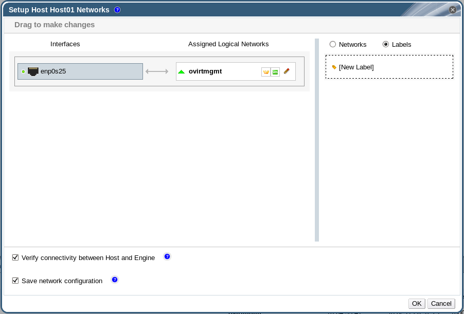
- Enter a name for the network label in the Label text field.
- Click .
6.5.6. Bonds
6.5.6.1. Bonding Logic in Red Hat Virtualization
- Are either of the devices already carrying logical networks?
- Are the devices carrying compatible logical networks?
| Bonding Scenario | Result |
|---|---|
|
NIC + NIC
|
The Create New Bond window is displayed, and you can configure a new bond device.
If the network interfaces carry incompatible logical networks, the bonding operation fails until you detach incompatible logical networks from the devices forming your new bond.
|
|
NIC + Bond
|
The NIC is added to the bond device. Logical networks carried by the NIC and the bond are all added to the resultant bond device if they are compatible.
If the bond devices carry incompatible logical networks, the bonding operation fails until you detach incompatible logical networks from the devices forming your new bond.
|
|
Bond + Bond
|
If the bond devices are not attached to logical networks, or are attached to compatible logical networks, a new bond device is created. It contains all of the network interfaces, and carries all logical networks, of the component bond devices. The Create New Bond window is displayed, allowing you to configure your new bond.
If the bond devices carry incompatible logical networks, the bonding operation fails until you detach incompatible logical networks from the devices forming your new bond.
|
6.5.6.2. Bonds
Important
Bonding Modes
Mode 0 (round-robin policy)- Transmits packets through network interface cards in sequential order. Packets are transmitted in a loop that begins with the first available network interface card in the bond and end with the last available network interface card in the bond. All subsequent loops then start with the first available network interface card. Mode 0 offers fault tolerance and balances the load across all network interface cards in the bond. However, Mode 0 cannot be used in conjunction with bridges, and is therefore not compatible with virtual machine logical networks.
Mode 1 (active-backup policy)- Sets all network interface cards to a backup state while one network interface card remains active. In the event of failure in the active network interface card, one of the backup network interface cards replaces that network interface card as the only active network interface card in the bond. The MAC address of the bond in Mode 1 is visible on only one port to prevent any confusion that might otherwise be caused if the MAC address of the bond changed to reflect that of the active network interface card. Mode 1 provides fault tolerance and is supported in Red Hat Virtualization.
Mode 2 (XOR policy)- Selects the network interface card through which to transmit packets based on the result of an XOR operation on the source and destination MAC addresses modulo network interface card slave count. This calculation ensures that the same network interface card is selected for each destination MAC address used. Mode 2 provides fault tolerance and load balancing and is supported in Red Hat Virtualization.
Mode 3 (broadcast policy)- Transmits all packets to all network interface cards. Mode 3 provides fault tolerance and is supported in Red Hat Virtualization.
Mode 4 (IEEE 802.3ad policy)- Creates aggregation groups in which the interfaces share the same speed and duplex settings. Mode 4 uses all network interface cards in the active aggregation group in accordance with the IEEE 802.3ad specification and is supported in Red Hat Virtualization.
Mode 5 (adaptive transmit load balancing policy)- Ensures the distribution of outgoing traffic accounts for the load on each network interface card in the bond and that the current network interface card receives all incoming traffic. If the network interface card assigned to receive traffic fails, another network interface card is assigned to the role of receiving incoming traffic. Mode 5 cannot be used in conjunction with bridges, therefore it is not compatible with virtual machine logical networks.
Mode 6 (adaptive load balancing policy)- Combines Mode 5 (adaptive transmit load balancing policy) with receive load balancing for IPv4 traffic without any special switch requirements. ARP negotiation is used for balancing the receive load. Mode 6 cannot be used in conjunction with bridges, therefore it is not compatible with virtual machine logical networks.
6.5.6.3. Creating a Bond Device Using the Administration Portal
Procedure 6.24. Creating a Bond Device using the Administration Portal
- Click the Hosts resource tab, and select the host in the results list.
- Click the Network Interfaces tab in the details pane to list the physical network interfaces attached to the host.
- Click to open the Setup Host Networks window.
- Select and drag one of the devices over the top of another device and drop it to open the Create New Bond window. Alternatively, right-click the device and select another device from the drop-down menu.If the devices are incompatible, the bond operation fails and suggests how to correct the compatibility issue.
- Select the Bond Name and Bonding Mode from the drop-down menus.Bonding modes 1, 2, 4, and 5 can be selected. Any other mode can be configured using the Custom option.
- Click to create the bond and close the Create New Bond window.
- Assign a logical network to the newly created bond device.
- Optionally choose to Verify connectivity between Host and Engine and Save network configuration.
- Click accept the changes and close the Setup Host Networks window.
Note
ad_partner_mac is reported as 00:00:00:00:00:00. The Manager will display a warning in the form of an exclamation mark icon on the bond in the Network Interfaces tab. No warning is provided if any of the slaves are up and running.
6.5.6.4. Example Uses of Custom Bonding Options with Host Interfaces
Example 6.1. xmit_hash_policy
mode=4 xmit_hash_policy=layer2+3
Example 6.2. ARP Monitoring
arp_interval on the bond device of the host by selecting a Custom bonding mode, and entering the following into the text field:
mode=1 arp_interval=1 arp_ip_target=192.168.0.2
Example 6.3. Primary
mode=1 primary=eth0
6.5.7. Changing the FQDN of a Host
Procedure 6.25. Updating the FQDN of a Host
- Place the host into maintenance mode so the virtual machines are live migrated to another host. See Section 7.5.8, “Moving a Host to Maintenance Mode” for more information. Alternatively, manually shut down or migrate all the virtual machines to another host. See Manually Migrating Virtual Machines in the Virtual Machine Management Guide for more information.
- Click , and click to remove the host from the Administration Portal.
- Use the hostnamectl tool to update the host name. For more options, see Configure Host Names in the Red Hat Enterprise Linux 7 Networking Guide.
# hostnamectl set-hostname NEW_FQDN
- Reboot the host.
- Re-register the host with the Manager. See Section 7.5.1, “Adding a Host to the Red Hat Virtualization Manager” for more information.
Chapter 7. Hosts
7.1. Introduction to Hosts
Note
- Must belong to only one cluster in the system.
- Must have CPUs that support the AMD-V or Intel VT hardware virtualization extensions.
- Must have CPUs that support all functionality exposed by the virtual CPU type selected upon cluster creation.
- Has a minimum of 2 GB RAM.
- Can have an assigned system administrator with system permissions.
7.2. Red Hat Virtualization Host
yum. Using the yum command is the only way to install additional packages and have them persist after an upgrade.
Note
grubby tool. The grubby tool makes persistent changes to the grub.cfg file. Navigate to the Terminal sub-tab in the host's Cockpit user interface to use grubby commands. See the Red Hat Enterprise Linux System Administrator's Guide for more information.
Warning
7.3. Red Hat Enterprise Linux Hosts
Red Hat Enterprise Linux Server entitlement and the Red Hat Virtualization entitlement.
Important
7.4. Satellite Host Provider Hosts
7.5. Host Tasks
7.5.1. Adding a Host to the Red Hat Virtualization Manager
Procedure 7.1. Adding a Host to the Red Hat Virtualization Manager
- From the Administration Portal, click the Hosts resource tab.
- Click .
- Use the drop-down list to select the Data Center and Host Cluster for the new host.
- Enter the Name and the Address of the new host. The standard SSH port, port 22, is auto-filled in the SSH Port field.
- Select an authentication method to use for the Manager to access the host.
- Enter the root user's password to use password authentication.
- Alternatively, copy the key displayed in the SSH PublicKey field to
/root/.ssh/authorized_keyson the host to use public key authentication.
- Click the button to expand the advanced host settings.
- Optionally disable automatic firewall configuration.
- Optionally add a host SSH fingerprint to increase security. You can add it manually, or fetch it automatically.
- Optionally configure Power Management, SPM, Console, Network Provider, and Kernel. See Section 7.5.5, “Explanation of Settings and Controls in the New Host and Edit Host Windows” for more information. Hosted Engine is used when deploying or undeploying a host for a self-hosted engine deployment.
- Click .
Installing, and you can view the progress of the installation in the details pane. After a brief delay the host status changes to Up.
Important
7.5.2. Adding a Satellite Host Provider Host
Procedure 7.2. Adding a Satellite Host Provider Host
- Click the Hosts resource tab to list the hosts in the results list.
- Click to open the New Host window.
- Use the drop-down menu to select the Host Cluster for the new host.
- Select the Foreman/Satellite check box to display the options for adding a Satellite host provider host and select the provider from which the host is to be added.
- Select either Discovered Hosts or Provisioned Hosts.
- Discovered Hosts (default option): Select the host, host group, and compute resources from the drop-down lists.
- Provisioned Hosts: Select a host from the Providers Hosts drop-down list.
Any details regarding the host that can be retrieved from the external provider are automatically set, and can be edited as desired. - Enter the Name, Address, and SSH Port (Provisioned Hosts only) of the new host.
- Select an authentication method to use with the host.
- Enter the root user's password to use password authentication.
- Copy the key displayed in the SSH PublicKey field to
/root/.ssh/authorized_hostson the host to use public key authentication (Provisioned Hosts only).
- You have now completed the mandatory steps to add a Red Hat Enterprise Linux host. Click the drop-down button to show the advanced host settings.
- Optionally disable automatic firewall configuration.
- Optionally add a host SSH fingerprint to increase security. You can add it manually, or fetch it automatically.
- You can configure the Power Management, SPM, Console, and Network Provider using the applicable tabs now; however, as these are not fundamental to adding a Red Hat Enterprise Linux host, they are not covered in this procedure.
- Click to add the host and close the window.
Installing, and you can view the progress of the installation in the details pane. After installation is complete, the status will update to Reboot. The host must be activated for the status to change to Up.
7.5.3. Configuring Satellite Errata Management for a Host
Important
Procedure 7.3. Configuring Satellite Errata Management for a Host
- Add the Satellite server as an external provider. See Section 12.2.1, “Adding a Red Hat Satellite Instance for Host Provisioning” for more information.
- Associate the required host with the Satellite server.
Note
The host must be registered to the Satellite server and have the katello-agent package installed.For more information on how to configure a host registration see Configuring a Host for Registration in the Red Hat Satellite User Guide and for more information on how to register a host and install the katello-agent package see Registration in the Red Hat Satellite User Guide- In the Hosts tab, select the host in the results list.
- Click to open the Edit Host window.
- Check the checkbox.
- Select the required Satellite server from the drop-down list.
- Click .
7.5.4. Adding a Red Hat OpenStack Platform Network Node as a Host
- You already have working knowledge of Red Hat OpenStack Platform.
- You have already added an OpenStack Networking external network provider to the Manager. See Section 12.2.3, “Adding an OpenStack Networking (Neutron) Instance for Network Provisioning”.
- The machine to be added as a host has no repositories currently enabled.
Procedure 7.4. Adding a Network Node as a Host
- Use the Red Hat OpenStack Platform director to deploy the Networker role on the network node. See Creating a New Role and Networker in the Red Hat OpenStack Platform Advanced Overcloud Customization Guide.
- Enable the Red Hat Virtualization repositories. See Subscribing to the Required Entitlements in the Installation Guide.
- Install the Openstack Networking hook:
# yum install vdsm-hook-openstacknet
- Add the network node to the Manager as a host. See Section 7.5.1, “Adding a Host to the Red Hat Virtualization Manager”.
Important
Do not select the OpenStack Networking provider from the Network Provider tab. This is currently not supported. - Remove the firewall rule that rejects ICMP traffic:
# iptables -D INPUT -j REJECT --reject-with icmp-host-prohibited
7.5.5. Explanation of Settings and Controls in the New Host and Edit Host Windows
7.5.5.1. Host General Settings Explained
|
Field Name
|
Description
|
|---|---|
|
Host Cluster
|
The cluster and data center to which the host belongs.
|
|
Use Foreman/Satellite
|
Select or clear this check box to view or hide options for adding hosts provided by Satellite host providers. The following options are also available:
Discovered Hosts
Provisioned Hosts
|
|
Name
|
The name of the cluster. This text field has a 40-character limit and must be a unique name with any combination of uppercase and lowercase letters, numbers, hyphens, and underscores.
|
|
Comment
|
A field for adding plain text, human-readable comments regarding the host.
|
|
Affinity Labels
|
Add or remove a selected Affinity Label.
|
|
Address
|
The IP address, or resolvable hostname of the host.
|
|
Password
|
The password of the host's root user. This can only be given when you add the host; it cannot be edited afterwards.
|
|
SSH PublicKey
|
Copy the contents in the text box to the
/root/.known_hosts file on the host to use the Manager's ssh key instead of using a password to authenticate with the host.
|
|
Automatically configure host firewall
|
When adding a new host, the Manager can open the required ports on the host's firewall. This is enabled by default. This is an Advanced Parameter.
|
|
SSH Fingerprint
|
You can the host's SSH fingerprint, and compare it with the fingerprint you expect the host to return, ensuring that they match. This is an Advanced Parameter.
|
7.5.5.2. Host Power Management Settings Explained
|
Field Name
|
Description
|
|---|---|
|
Enable Power Management
|
Enables power management on the host. Select this check box to enable the rest of the fields in the Power Management tab.
|
|
Kdump integration
|
Prevents the host from fencing while performing a kernel crash dump, so that the crash dump is not interrupted. In Red Hat Enterprise Linux 7.1 and later, kdump is available by default. If kdump is available on the host, but its configuration is not valid (the kdump service cannot be started), enabling Kdump integration will cause the host (re)installation to fail. If this is the case, see Section 7.6.4, “fence_kdump Advanced Configuration”.
|
|
Disable policy control of power management
|
Power management is controlled by the Scheduling Policy of the host's cluster. If power management is enabled and the defined low utilization value is reached, the Manager will power down the host machine, and restart it again when load balancing requires or there are not enough free hosts in the cluster. Select this check box to disable policy control.
|
|
Agents by Sequential Order
|
Lists the host's fence agents. Fence agents can be sequential, concurrent, or a mix of both.
Fence agents are sequential by default. Use the up and down buttons to change the sequence in which the fence agents are used.
To make two fence agents concurrent, select one fence agent from the Concurrent with drop-down list next to the other fence agent. Additional fence agents can be added to the group of concurrent fence agents by selecting the group from the Concurrent with drop-down list next to the additional fence agent.
|
|
Add Fence Agent
|
Click the plus () button to add a new fence agent. The Edit fence agent window opens. See the table below for more information on the fields in this window.
|
|
Power Management Proxy Preference
|
By default, specifies that the Manager will search for a fencing proxy within the same cluster as the host, and if no fencing proxy is found, the Manager will search in the same dc (data center). Use the up and down buttons to change the sequence in which these resources are used. This field is available under Advanced Parameters.
|
|
Field Name
|
Description
|
|---|---|
|
Address
|
The address to access your host's power management device. Either a resolvable hostname or an IP address.
|
|
User Name
|
User account with which to access the power management device. You can set up a user on the device, or use the default user.
|
|
Password
|
Password for the user accessing the power management device.
|
|
Type
|
The type of power management device in your host.
Choose one of the following:
For more information about power management devices, see Power Management in the Technical Reference.
|
|
Port
|
The port number used by the power management device to communicate with the host.
|
|
Slot
|
The number used to identify the blade of the power management device.
|
|
Service Profile
|
The service profile name used to identify the blade of the power management device. This field appears instead of Slot when the device type is
cisco_ucs.
|
|
Options
|
Power management device specific options. Enter these as 'key=value'. See the documentation of your host's power management device for the options available.
For Red Hat Enterprise Linux 7 hosts, if you are using cisco_ucs as the power management device, you also need to append
ssl_insecure=1 to the Options field.
|
|
Secure
|
Select this check box to allow the power management device to connect securely to the host. This can be done via ssh, ssl, or other authentication protocols depending on the power management agent.
|
7.5.5.3. SPM Priority Settings Explained
|
Field Name
|
Description
|
|---|---|
|
SPM Priority
|
Defines the likelihood that the host will be given the role of Storage Pool Manager (SPM). The options are Low, Normal, and High priority. Low priority means that there is a reduced likelihood of the host being assigned the role of SPM, and High priority means there is an increased likelihood. The default setting is Normal.
|
7.5.5.4. Host Console Settings Explained
|
Field Name
|
Description
|
|---|---|
|
Override display address
|
Select this check box to override the display addresses of the host. This feature is useful in a case where the hosts are defined by internal IP and are behind a NAT firewall. When a user connects to a virtual machine from outside of the internal network, instead of returning the private address of the host on which the virtual machine is running, the machine returns a public IP or FQDN (which is resolved in the external network to the public IP).
|
|
Display address
|
The display address specified here will be used for all virtual machines running on this host. The address must be in the format of a fully qualified domain name or IP.
|
7.5.5.5. Network Provider Settings Explained
|
Field Name
|
Description
|
|---|---|
|
External Network Provider
|
If you have added an external network provider and want the host's network to be provisioned by the external network provider, select one from the list.
|
7.5.5.6. Kernel Settings Explained
Important
|
Field Name
|
Description
|
|---|---|
|
Hostdev Passthrough & SR-IOV
|
Enables the IOMMU flag in the kernel to allow a host device to be used by a virtual machine as if the device is a device attached directly to the virtual machine itself. The host hardware and firmware must also support IOMMU. The virtualization extension and IOMMU extension must be enabled on the hardware. See Configuring a Host for PCI Passthrough in the Installation Guide. IBM POWER8 has IOMMU enabled by default.
|
|
Nested Virtualization
|
Enables the vmx or svm flag to allow you to run virtual machines within virtual machines. This option is only intended for evaluation purposes and not supported for production purposes. The
vdsm-hook-nestedvt hook must be installed on the host.
|
|
Unsafe Interrupts
|
If IOMMU is enabled but the passthrough fails because the hardware does not support interrupt remapping, you can consider enabling this option. Note that you should only enable this option if the virtual machines on the host are trusted; having the option enabled potentially exposes the host to MSI attacks from the virtual machines. This option is only intended to be used as a workaround when using uncertified hardware for evaluation purposes.
|
|
PCI Reallocation
|
If your SR-IOV NIC is unable to allocate virtual functions because of memory issues, consider enabling this option. The host hardware and firmware must also support PCI reallocation. This option is only intended to be used as a workaround when using uncertified hardware for evaluation purposes.
|
|
Kernel command line
|
This field allows you to append more kernel parameters to the default parameters.
|
Note
7.5.5.7. Hosted Engine Settings Explained
|
Field Name
|
Description
|
|---|---|
|
Choose hosted engine deployment action
|
Three options are available:
|
7.5.6. Configuring Host Power Management Settings
Important
maintenance mode before configuring power management settings. Otherwise, all running virtual machines on that host will be stopped ungracefully upon restarting the host, which can cause disruptions in production environments. A warning dialog will appear if you have not correctly set your host to maintenance mode.
Procedure 7.5. Configuring Power Management Settings
- In the Hosts tab, select the host in the results list.
- Click to open the Edit Host window.
- Click the Power Management tab to display the Power Management settings.
- Select the Enable Power Management check box to enable the fields.
- Select the Kdump integration check box to prevent the host from fencing while performing a kernel crash dump.
Important
When you enable Kdump integration on an existing host, the host must be reinstalled for kdump to be configured. See Section 7.5.12, “Reinstalling Hosts”. - Optionally, select the Disable policy control of power management check box if you do not want your host's power management to be controlled by the Scheduling Policy of the host's cluster.
- Click the plus () button to add a new power management device. The Edit fence agent window opens. For information about this window, see Section 7.5.5.2, “Host Power Management Settings Explained”
- Enter the User Name and Password of the power management device into the appropriate fields.
- Select the power management device Type in the drop-down list.
- Enter the IP address in the Address field.
- Enter the SSH Port number used by the power management device to communicate with the host.
- Enter the Slot number used to identify the blade of the power management device.
- Enter the Options for the power management device. Use a comma-separated list of 'key=value' entries.
- If both IPv4 and IPv6 IP addresses can be used (default), leave the Options field blank.
- If only IPv4 IP addresses can be used, enter
inet4_only=1. - If only IPv6 IP addresses can be used, enter
inet6_only=1.
- Select the Secure check box to enable the power management device to connect securely to the host.
- Click to ensure the settings are correct. Test Succeeded, Host Status is: on will display upon successful verification.If the host is powered off, you will see Test Succeeded, Host Status is: offIf the test fails, the default settings that are configured when selecting the power management device type may not match your configuration. This occurs when you change the default fence settings on your hardware. To resolve the problem, update the fence agent settings as follows:
- Install the
fence-agentspackage.yum install fence-agents
- Open the man page for the agent and search for
STDIN Parameterssection. This contains the names of the parameters that you will need to manually edit. For example, for ilo4 type:man fence_ilo4
- Check your hardware configuration and determine which value(s) you have changed.
- In the Options field in the Edit fence agent window, add the relevant parameter according to the man page and enter the required value according to your configuration.
- Click to determine if the change was successful. If it was not, check the hardware configuration for additional changes that you have made and repeat the procedure.
- Click to close the Edit fence agent window.
- In the Power Management tab, optionally expand the Advanced Parameters and use the up and down buttons to specify the order in which the Manager will search the host's cluster and dc (datacenter) for a fencing proxy.
- Click .
7.5.7. Configuring Host Storage Pool Manager Settings
Procedure 7.6. Configuring SPM settings
- Click the Hosts resource tab, and select a host from the results list.
- Click to open the Edit Host window.
- Click the SPM tab to display the SPM Priority settings.
- Use the radio buttons to select the appropriate SPM priority for the host.
- Click to save the settings and close the window.
7.5.8. Moving a Host to Maintenance Mode
Procedure 7.7. Placing a Host into Maintenance Mode
- Click the Hosts resource tab, and select the desired host.
- Click → to open the Maintenance Host(s) confirmation window.
- Optionally, enter a Reason for moving the host into maintenance mode in the Maintenance Host(s) confirmation window. This allows you to provide an explanation for the maintenance, which will appear in the logs and when the host is activated again.
Note
The host maintenance Reason field will only appear if it has been enabled in the cluster settings. See Section 5.2.2.1, “General Cluster Settings Explained” for more information. - Optionally, select the required options for hosts that support Gluster.Select the Ignore Gluster Quorum and Self-Heal Validations option to avoid the default checks. By default, the Manager checks that the Gluster quorum is not lost when the host is moved to maintenance mode. The Manager also checks that there is no self-heal activity that will be affected by moving the host to maintenance mode. If the Gluster quorum will be lost or if there is self-heal activity that will be affected, the Manager prevents the host from being placed into maintenance mode. Only use this option if there is no other way to place the host in maintenance mode.Select the Stop Gluster Service option to stop all Gluster services while moving the host to maintenance mode.
Note
These fields will only appear in the host maintenance window when the selected host supports Gluster. See Replacing the Primary Gluster Storage Node in Maintaining Red Hat Hyperconverged Infrastructure for more information. - Click to initiate maintenance mode.
Preparing for Maintenance, and finally Maintenance when the operation completes successfully. VDSM does not stop while the host is in maintenance mode.
Note
7.5.9. Activating a Host from Maintenance Mode
Procedure 7.8. Activating a Host from Maintenance Mode
- Click the Hosts resources tab and select the host.
- Click → .
Unassigned, and finally Up when the operation is complete. Virtual machines can now run on the host. Virtual machines that were migrated off the host when it was placed into maintenance mode are not automatically migrated back to the host when it is activated, but can be migrated manually. If the host was the Storage Pool Manager (SPM) before being placed into maintenance mode, the SPM role does not return automatically when the host is activated.
7.5.10. Removing a Host
Procedure 7.9. Removing a host
- In the Administration Portal, click the Hosts resource tab and select the host in the results list.
- Place the host into maintenance mode.
- Click to open the Remove Host(s) confirmation window.
- Select the Force Remove check box if the host is part of a Red Hat Gluster Storage cluster and has volume bricks on it, or if the host is non-responsive.
- Click .
7.5.11. Updating a Host Between Minor Releases
7.5.12. Reinstalling Hosts
Important
Procedure 7.10. Reinstalling Red Hat Virtualization Host or Red Hat Enterprise Linux hosts
- Use the Hosts resource tab, tree mode, or the search function to find and select the host in the results list.
- Click → . If migration is enabled at cluster level, any virtual machines running on the host are migrated to other hosts. If the host is the SPM, this function is moved to another host. The status of the host changes as it enters maintenance mode.
- Click → to open the Install Host window.
- Click to reinstall the host.
Important
7.5.13. Customizing Hosts with Tags
Procedure 7.11. Customizing hosts with tags
- Use the Hosts resource tab, tree mode, or the search function to find and select the host in the results list.
- Click to open the Assign Tags window.
Figure 7.1. Assign Tags Window
- The Assign Tags window lists all available tags. Select the check boxes of applicable tags.
- Click to assign the tags and close the window.
7.5.14. Viewing Host Errata
Procedure 7.12. Viewing Host Errata
- Click the Hosts resource tab, and select a host from the results list.
- Click the General tab in the details pane.
- Click the Errata sub-tab in the General tab.
7.5.15. Viewing the Health Status of a Host
- OK: No icon
- Info:

- Warning:

- Error:

- Failure:

GET request on a host will include the external_status element, which contains the health status.
events collection. For more information, see Adding Events in the REST API Guide.
7.5.16. Viewing Host Devices
Procedure 7.13. Viewing Host Devices
- Use the Hosts resource tab, tree mode, or the search function to find and select a host from the results list.
- Click the Host Devices tab in the details pane.
7.5.17. Preparing Host and Guest Systems for GPU Passthrough
grub configuration files. You can edit the host grub configuration file using the Kernel command line free text entry field in the Administration Portal. Both the host machine and the virtual machine require reboot for the changes to take effect.
Important
Procedure 7.14. Preparing a Host for GPU Passthrough
- From the Administration Portal, select a host.
- Click the General tab in the details pane, and click Hardware. Locate the GPU device vendor ID:product ID. In this example, the IDs are
10de:13baand10de:0fbc. - Right-click the host and select Edit. Click the Kernel tab.
- In the Kernel command line free text entry field, enter the IDs located in the previous steps.
pci-stub.ids=10de:13ba,10de:0fbc
- Blacklist the corresponding drivers on the host. For example, to blacklist nVidia's nouveau driver, next to pci-stub.ids=xxxx:xxxx, enter rdblacklist=nouveau.
pci-stub.ids=10de:13ba,10de:0fbc rdblacklist=nouveau
- Click to save the changes.
- Click → to commit the changes to the host.
- Reboot the host after the reinstallation is complete.
Note
pci-stub driver, run the lspci command:
# lspci -nnk
...
01:00.0 VGA compatible controller [0300]: NVIDIA Corporation GM107GL [Quadro K2200] [10de:13ba] (rev a2)
        Subsystem: NVIDIA Corporation Device [10de:1097]
        Kernel driver in use: pci-stub
01:00.1 Audio device [0403]: NVIDIA Corporation Device [10de:0fbc] (rev a1)
        Subsystem: NVIDIA Corporation Device [10de:1097]
        Kernel driver in use: pci-stub
...
grub configuration file manually, see Preparing Host and Guest Systems for GPU Passthrough in the 3.6 Administration Guide.
Procedure 7.15. Preparing a Guest Virtual Machine for GPU Passthrough
- For Linux
- Only proprietary GPU drivers are supported. Black list the corresponding open source driver in the
grubconfiguration file. For example:$ vi /etc/default/grub ... GRUB_CMDLINE_LINUX="nofb splash=quiet console=tty0 ... rdblacklist=nouveau" ...
- Locate the GPU BusID. In this example, is BusID is
00:09.0.# lspci | grep VGA 00:09.0 VGA compatible controller: NVIDIA Corporation GK106GL [Quadro K4000] (rev a1)
- Edit the
/etc/X11/xorg.conffile and append the following content:Section "Device" Identifier "Device0" Driver "nvidia" VendorName "NVIDIA Corporation" BusID "PCI:0:9:0" EndSection
- Restart the virtual machine.
- For Windows
- Download and install the corresponding drivers for the device. For example, for Nvidia drivers, go to NVIDIA Driver Downloads.
- Restart the virtual machine.
7.5.18. Accessing Cockpit from the Administration Portal
Procedure 7.16. Accessing Cockpit from the Administration Portal
- Install the Cockpit UI plug-in on the Manager machine:
# yum install cockpit-ovirt-uiplugin
- Restart the
ovirt-engineservice:# systemctl restart ovirt-engine.service
- In the Administration Portal, click the Hosts tab and select a host.
- Open the Cockpit user interface in a new tab, or view it directly through the Administration Portal:
- Right-click the host and select to open the Cockpit user interface in a new browser tab.
- Click the Cockpit sub-tab to view the Cockpit user interface in the details pane of the Hosts tab.
Note
If Cockpit is not available on the selected host, the Cockpit sub-tab shows basic troubleshooting steps.
7.6. Host Resilience
7.6.1. Host High Availability
7.6.2. Power Management by Proxy in Red Hat Virtualization
- Any host in the same cluster as the host requiring fencing.
- Any host in the same data center as the host requiring fencing.
7.6.3. Setting Fencing Parameters on a Host
Procedure 7.17. Setting fencing parameters on a host
- Use the Hosts resource tab, tree mode, or the search function to find and select the host in the results list.
- Click to open the Edit Host window.
- Click the Power Management tab.
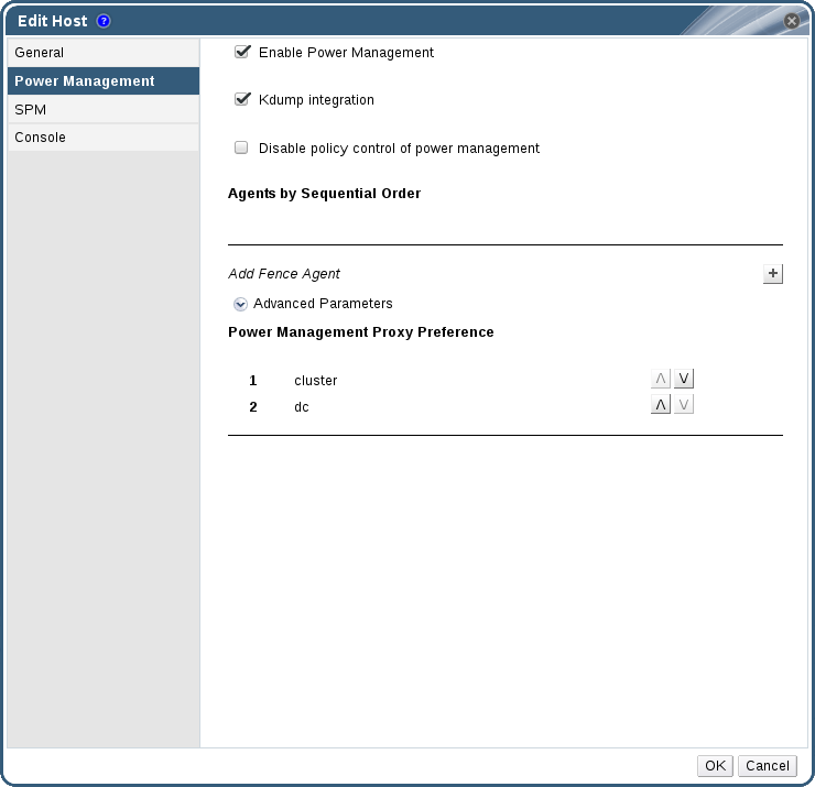
Figure 7.2. Power Management Settings
- Select the Enable Power Management check box to enable the fields.
- Select the Kdump integration check box to prevent the host from fencing while performing a kernel crash dump.
Important
When you enable Kdump integration on an existing host, the host must be reinstalled for kdump to be configured. See Section 7.5.12, “Reinstalling Hosts”. - Optionally, select the Disable policy control of power management check box if you do not want your host's power management to be controlled by the Scheduling Policy of the host's cluster.
- Click the plus () button to add a new power management device. The Edit fence agent window opens.

Figure 7.3. Edit fence agent
- Enter the Address, User Name, and Password of the power management device.
- Select the power management device Type from the drop-down list.
Note
For more information on how to set up a custom power management device, see https://access.redhat.com/articles/1238743. - Enter the SSH Port number used by the power management device to communicate with the host.
- Enter the Slot number used to identify the blade of the power management device.
- Enter the Options for the power management device. Use a comma-separated list of 'key=value' entries.
- Select the Secure check box to enable the power management device to connect securely to the host.
- Click the button to ensure the settings are correct. Test Succeeded, Host Status is: on will display upon successful verification.
Warning
Power management parameters (userid, password, options, etc) are tested by Red Hat Virtualization Manager only during setup and manually after that. If you choose to ignore alerts about incorrect parameters, or if the parameters are changed on the power management hardware without the corresponding change in Red Hat Virtualization Manager, fencing is likely to fail when most needed. - Click to close the Edit fence agent window.
- In the Power Management tab, optionally expand the Advanced Parameters and use the up and down buttons to specify the order in which the Manager will search the host's cluster and dc (datacenter) for a fencing proxy.
- Click .
7.6.4. fence_kdump Advanced Configuration
Select a host to view the status of the kdump service in the General tab of the details pane:
- Enabled: kdump is configured properly and the kdump service is running.
- Disabled: the kdump service is not running (in this case kdump integration will not work properly).
- Unknown: happens only for hosts with an earlier VDSM version that does not report kdump status.
Enabling Kdump integration in the Power Management tab of the New Host or Edit Host window configures a standard fence_kdump setup. If the environment's network configuration is simple and the Manager's FQDN is resolvable on all hosts, the default fence_kdump settings are sufficient for use.
engine-config:
engine-config -s FenceKdumpDestinationAddress=A.B.C.D
- The Manager has two NICs, where one of these is public-facing, and the second is the preferred destination for fence_kdump messages.
- You need to execute the fence_kdump listener on a different IP or port.
- You need to set a custom interval for fence_kdump notification messages, to prevent possible packet loss.
7.6.4.1. fence_kdump listener Configuration
Procedure 7.18. Manually Configuring the fence_kdump Listener
- Create a new file (for example,
my-fence-kdump.conf) in/etc/ovirt-engine/ovirt-fence-kdump-listener.conf.d/ - Enter your customization with the syntax OPTION=value and save the file.
Important
The edited values must also be changed inengine-configas outlined in the fence_kdump Listener Configuration Options table in Section 7.6.4.2, “Configuring fence_kdump on the Manager”. - Restart the fence_kdump listener:
# systemctl restart ovirt-fence-kdump-listener.service
| Variable | Description | Default | Note |
|---|---|---|---|
| LISTENER_ADDRESS | Defines the IP address to receive fence_kdump messages on. | 0.0.0.0 | If the value of this parameter is changed, it must match the value of FenceKdumpDestinationAddress in engine-config. |
| LISTENER_PORT | Defines the port to receive fence_kdump messages on. | 7410 | If the value of this parameter is changed, it must match the value of FenceKdumpDestinationPort in engine-config. |
| HEARTBEAT_INTERVAL | Defines the interval in seconds of the listener's heartbeat updates. | 30 | If the value of this parameter is changed, it must be half the size or smaller than the value of FenceKdumpListenerTimeout in engine-config. |
| SESSION_SYNC_INTERVAL | Defines the interval in seconds to synchronize the listener's host kdumping sessions in memory to the database. | 5 | If the value of this parameter is changed, it must be half the size or smaller than the value of KdumpStartedTimeout in engine-config. |
| REOPEN_DB_CONNECTION_INTERVAL | Defines the interval in seconds to reopen the database connection which was previously unavailable. | 30 | - |
| KDUMP_FINISHED_TIMEOUT | Defines the maximum timeout in seconds after the last received message from kdumping hosts after which the host kdump flow is marked as FINISHED. | 60 | If the value of this parameter is changed, it must be double the size or higher than the value of FenceKdumpMessageInterval in engine-config. |
7.6.4.2. Configuring fence_kdump on the Manager
# engine-config -g OPTION
Procedure 7.19. Manually Configuring Kdump with engine-config
- Edit kdump's configuration using the
engine-configcommand:# engine-config -s OPTION=value
Important
The edited values must also be changed in the fence_kdump listener configuration file as outlined in theKdump Configuration Optionstable. See Section 7.6.4.1, “fence_kdump listener Configuration”. - Restart the
ovirt-engineservice:# systemctl restart ovirt-engine.service
- Reinstall all hosts with Kdump integration enabled, if required (see the table below).
engine-config:
| Variable | Description | Default | Note |
|---|---|---|---|
| FenceKdumpDestinationAddress | Defines the hostname(s) or IP address(es) to send fence_kdump messages to. If empty, the Manager's FQDN is used. | Empty string (Manager FQDN is used) | If the value of this parameter is changed, it must match the value of LISTENER_ADDRESS in the fence_kdump listener configuration file, and all hosts with Kdump integration enabled must be reinstalled. |
| FenceKdumpDestinationPort | Defines the port to send fence_kdump messages to. | 7410 | If the value of this parameter is changed, it must match the value of LISTENER_PORT in the fence_kdump listener configuration file, and all hosts with Kdump integration enabled must be reinstalled. |
| FenceKdumpMessageInterval | Defines the interval in seconds between messages sent by fence_kdump. | 5 | If the value of this parameter is changed, it must be half the size or smaller than the value of KDUMP_FINISHED_TIMEOUT in the fence_kdump listener configuration file, and all hosts with Kdump integration enabled must be reinstalled. |
| FenceKdumpListenerTimeout | Defines the maximum timeout in seconds since the last heartbeat to consider the fence_kdump listener alive. | 90 | If the value of this parameter is changed, it must be double the size or higher than the value of HEARTBEAT_INTERVAL in the fence_kdump listener configuration file. |
| KdumpStartedTimeout | Defines the maximum timeout in seconds to wait until the first message from the kdumping host is received (to detect that host kdump flow has started). | 30 | If the value of this parameter is changed, it must be double the size or higher than the value of SESSION_SYNC_INTERVAL in the fence_kdump listener configuration file, and FenceKdumpMessageInterval. |
7.6.5. Soft-Fencing Hosts
- On the first network failure, the status of the host changes to "connecting".
- The Manager then makes three attempts to ask VDSM for its status, or it waits for an interval determined by the load on the host. The formula for determining the length of the interval is configured by the configuration values TimeoutToResetVdsInSeconds (the default is 60 seconds) + [DelayResetPerVmInSeconds (the default is 0.5 seconds)]*(the count of running virtual machines on host) + [DelayResetForSpmInSeconds (the default is 20 seconds)] * 1 (if host runs as SPM) or 0 (if the host does not run as SPM). To give VDSM the maximum amount of time to respond, the Manager chooses the longer of the two options mentioned above (three attempts to retrieve the status of VDSM or the interval determined by the above formula).
- If the host does not respond when that interval has elapsed,
vdsm restartis executed via SSH. - If
vdsm restartdoes not succeed in re-establishing the connection between the host and the Manager, the status of the host changes toNon Responsiveand, if power management is configured, fencing is handed off to the external fencing agent.
Note
7.6.6. Using Host Power Management Functions
When power management has been configured for a host, you can access a number of options from the Administration Portal interface. While each power management device has its own customizable options, they all support the basic options to start, stop, and restart a host.
Procedure 7.20. Using Host Power Management Functions
- Use the Hosts resource tab, tree mode, or the search function to find and select the host in the results list.
- Click the → drop-down menu.
- Select one of the following options:
- Restart: This option stops the host and waits until the host's status changes to
Down. When the agent has verified that the host is down, the highly available virtual machines are restarted on another host in the cluster. The agent then restarts this host. When the host is ready for use its status displays asUp. - Start: This option starts the host and lets it join a cluster. When it is ready for use its status displays as
Up. - Stop: This option powers off the host. Before using this option, ensure that the virtual machines running on the host have been migrated to other hosts in the cluster. Otherwise the virtual machines will crash and only the highly available virtual machines will be restarted on another host. When the host has been stopped its status displays as
Non-Operational.
Note
If Power Management is not enabled, you can restart or stop the host by selecting it, clicking the Management drop-down menu, and selecting → or Stop.Important
When two fencing agents are defined on a host, they can be used concurrently or sequentially. For concurrent agents, both agents have to respond to the Stop command for the host to be stopped; and when one agent responds to the Start command, the host will go up. For sequential agents, to start or stop a host, the primary agent is used first; if it fails, the secondary agent is used. - Selecting one of the above options opens a confirmation window. Click OK to confirm and proceed.
The selected action is performed.
7.6.7. Manually Fencing or Isolating a Non-responsive Host
Warning
Procedure 7.21. Manually fencing or isolating a non-responsive host
- On the Hosts tab, select the host. The status must display as
non-responsive. - Manually reboot the host. This could mean physically entering the lab and rebooting the host.
- On the Administration Portal, right-click the host entry and select the button.
- A message displays prompting you to ensure that the host has been shut down or rebooted. Select the Approve Operation check box and click OK.
- If your hosts take an unusually long time to boot, you can set
ServerRebootTimeoutto specify how many seconds to wait before determining that the host isNon Responsive:# engine-config --set ServerRebootTimeout=integer
7.7. Hosts and Permissions
7.7.1. Managing System Permissions for a Host
- Edit the configuration of the host.
- Set up the logical networks.
- Remove the host.
7.7.2. Host Administrator Roles Explained
The table below describes the administrator roles and privileges applicable to host administration.
| Role | Privileges | Notes |
|---|---|---|
| HostAdmin | Host Administrator | Can configure, manage, and remove a specific host. Can also perform network-related operations on a specific host. |
7.7.3. Assigning an Administrator or User Role to a Resource
Procedure 7.22. Assigning a Role to a Resource
- Use the resource tabs, tree mode, or the search function to find and select the resource in the results list.
- Click the tab in the details pane to list the assigned users, the user's role, and the inherited permissions for the selected resource.
- Click .
- Enter the name or user name of an existing user into the Search text box and click . Select a user from the resulting list of possible matches.
- Select a role from the Role to Assign: drop-down list.
- Click .
7.7.4. Removing an Administrator or User Role from a Resource
Procedure 7.23. Removing a Role from a Resource
- Use the resource tabs, tree mode, or the search function to find and select the resource in the results list.
- Click the tab in the details pane to list the assigned users, the user's role, and the inherited permissions for the selected resource.
- Select the user to remove from the resource.
- Click . The Remove Permission window opens to confirm permissions removal.
- Click .
Chapter 8. Storage
- Network File System (NFS)
- GlusterFS exports
- CephFS
- Other POSIX compliant file systems
- Internet Small Computer System Interface (iSCSI)
- Local storage attached directly to the virtualization hosts
- Fibre Channel Protocol (FCP)
- Parallel NFS (pNFS)
- Data Domain: A data domain holds the virtual hard disks and OVF files of all the virtual machines and templates in a data center. In addition, snapshots of the virtual machines are also stored in the data domain.The data domain cannot be shared across data centers. Data domains of multiple types (iSCSI, NFS, FC, POSIX, and Gluster) can be added to the same data center, provided they are all shared, rather than local, domains.You must attach a data domain to a data center before you can attach domains of other types to it.
- ISO Domain: ISO domains store ISO files (or logical CDs) used to install and boot operating systems and applications for the virtual machines. An ISO domain removes the data center's need for physical media. An ISO domain can be shared across different data centers. ISO domains can only be NFS-based. Only one ISO domain can be added to a data center.
- Export Domain: Export domains are temporary storage repositories that are used to copy and move images between data centers and Red Hat Virtualization environments. Export domains can be used to backup virtual machines. An export domain can be moved between data centers, however, it can only be active in one data center at a time. Export domains can only be NFS-based. Only one export domain can be added to a data center.
Note
The export storage domain is deprecated. Storage data domains can be unattached from a data center and imported to another data center in the same environment, or in a different environment. Virtual machines, floating virtual disks, and templates can then be uploaded from the imported storage domain to the attached data center. See Section 8.6, “Importing Existing Storage Domains” for information on importing storage domains.
Important
8.1. Understanding Storage Domains
8.2. Preparing and Adding NFS Storage
8.2.1. Preparing NFS Storage
Note
Procedure 8.1. Configuring the Required System User Accounts and System User Groups
- Create the group
kvm:# groupadd kvm -g 36
- Create the user
vdsmin the groupkvm:# useradd vdsm -u 36 -g 36
- Set the ownership of your exported directories to 36:36, which gives vdsm:kvm ownership:
# chown -R 36:36 /exports/data
# chown -R 36:36 /exports/export
- Change the mode of the directories so that read and write access is granted to the owner, and so that read and execute access is granted to the group and other users:
# chmod 0755 /exports/data
# chmod 0755 /exports/export
8.2.2. Attaching NFS Storage
- In the Red Hat Virtualization Manager Administration Portal, click the resource tab.
- Click .
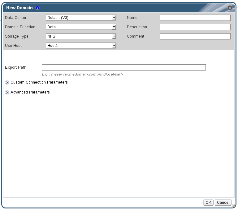
Figure 8.1. The New Domain Window
- Enter a Name for the storage domain.
- Accept the default values for the Data Center, Domain Function, Storage Type, Format, and Use Host lists.
- Enter the Export Path to be used for the storage domain.The export path should be in the format of 192.168.0.10:/data or domain.example.com:/data.
- Optionally, you can configure the advanced parameters.
- Click Advanced Parameters.
- Enter a percentage value into the Warning Low Space Indicator field. If the free space available on the storage domain is below this percentage, warning messages are displayed to the user and logged.
- Enter a GB value into the Critical Space Action Blocker field. If the free space available on the storage domain is below this value, error messages are displayed to the user and logged, and any new action that consumes space, even temporarily, will be blocked.
- Select the Wipe After Delete check box to enable the wipe after delete option. This option can be edited after the domain is created, but doing so will not change the wipe after delete property of disks that already exist.
- Click OK.The new NFS data domain is displayed in the Storage tab with a status of
Lockeduntil the disk is prepared. The data domain is then automatically attached to the data center.
8.2.3. Increasing NFS Storage
Procedure 8.2. Increasing an Existing NFS Storage Domain
- Click the Storage resource tab and select an NFS storage domain.
- In the details pane, click the Data Center tab and click the button to place the storage domain into maintenance mode. This unmounts the existing share and makes it possible to resize the storage domain.
- On the NFS server, resize the storage. For Red Hat Enterprise Linux 6 systems, see Red Hat Enterprise Linux 6 Storage Administration Guide. For Red Hat Enterprise Linux 7 systems, see Red Hat Enterprise Linux 7 Storage Administration Guide.
- In the details pane, click the Data Center tab and click the button to mount the storage domain.
8.3. Preparing and Adding Local Storage
8.3.1. Preparing Local Storage
Note
Important
/var directory. For RHVH, prepend /var to the directories in the Preparing Local Storage procedure.
/var directory will be lost when Red Had Virtualization Host is reinstalled. To avoid this, you can mount external storage to a host machine for use as a local storage domain. For more information on mounting storage, see the Red Hat Enterprise Linux Storage Administration Guide.
Procedure 8.3. Preparing Local Storage
- On the host, create the directory to be used for the local storage.
# mkdir -p /data/images
- Ensure that the directory has permissions allowing read/write access to the
vdsmuser (UID 36) andkvmgroup (GID 36).# chown 36:36 /data /data/images
# chmod 0755 /data /data/images
8.3.2. Adding Local Storage
Procedure 8.4. Adding Local Storage
- Click the Hosts resource tab, and select a host in the results list.
- Click → to open the Maintenance Host(s) confirmation window.
- Click to initiate maintenance mode.
- Click → .
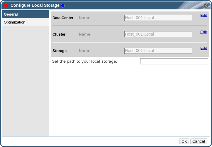
Figure 8.2. Configure Local Storage Window
- Click the buttons next to the Data Center, Cluster, and Storage fields to configure and name the local storage domain.
- Set the path to your local storage in the text entry field.
- If applicable, select the Optimization tab to configure the memory optimization policy for the new local storage cluster.
- Click to save the settings and close the window.
8.4. Adding POSIX Compliant File System Storage
Important
8.4.1. Attaching POSIX Compliant File System Storage
Procedure 8.5. Attaching POSIX Compliant File System Storage
- Click the Storage resource tab to list the existing storage domains in the results list.
- Click to open the New Domain window.
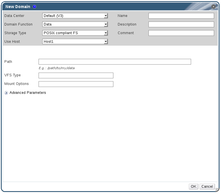
Figure 8.3. POSIX Storage
- Enter the Name for the storage domain.
- Select the Data Center to be associated with the storage domain. The Data Center selected must be of type POSIX (POSIX compliant FS). Alternatively, select
(none). - Select
Data / POSIX compliant FSfrom the Domain Function / Storage Type drop-down menu.If applicable, select the Format from the drop-down menu. - Select a host from the Use Host drop-down menu. Only hosts within the selected data center will be listed. The host that you select will be used to connect the storage domain.
- Enter the Path to the POSIX file system, as you would normally provide it to the
mountcommand. - Enter the VFS Type, as you would normally provide it to the
mountcommand using the-targument. Seeman mountfor a list of valid VFS types. - Enter additional Mount Options, as you would normally provide them to the
mountcommand using the-oargument. The mount options should be provided in a comma-separated list. Seeman mountfor a list of valid mount options. - Optionally, you can configure the advanced parameters.
- Click Advanced Parameters.
- Enter a percentage value into the Warning Low Space Indicator field. If the free space available on the storage domain is below this percentage, warning messages are displayed to the user and logged.
- Enter a GB value into the Critical Space Action Blocker field. If the free space available on the storage domain is below this value, error messages are displayed to the user and logged, and any new action that consumes space, even temporarily, will be blocked.
- Select the Wipe After Delete check box to enable the wipe after delete option. This option can be edited after the domain is created, but doing so will not change the wipe after delete property of disks that already exist.
- Click to attach the new Storage Domain and close the window.
8.5. Adding Block Storage
Important
Important
8.5.1. Adding iSCSI Storage
Procedure 8.6. Adding iSCSI Storage
- Click the Storage resource tab to list the existing storage domains in the results list.
- Click the button to open the New Domain window.
- Enter the Name of the new storage domain.
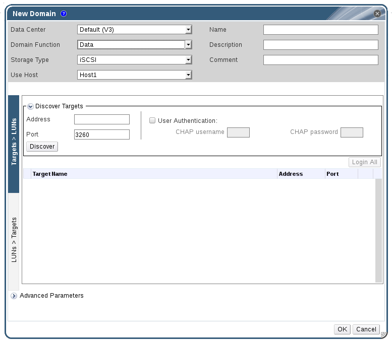
Figure 8.4. New iSCSI Domain
- Use the Data Center drop-down menu to select an data center.
- Use the drop-down menus to select the Domain Function and the Storage Type. The storage domain types that are not compatible with the chosen domain function are not available.
- Select an active host in the Use Host field. If this is not the first data domain in a data center, you must select the data center's SPM host.
Important
All communication to the storage domain is through the selected host and not directly from the Red Hat Virtualization Manager. At least one active host must exist in the system and be attached to the chosen data center. All hosts must have access to the storage device before the storage domain can be configured. - The Red Hat Virtualization Manager is able to map either iSCSI targets to LUNs, or LUNs to iSCSI targets. The New Domain window automatically displays known targets with unused LUNs when iSCSI is selected as the storage type. If the target that you are adding storage from is not listed then you can use target discovery to find it, otherwise proceed to the next step.
iSCSI Target Discovery
- Click Discover Targets to enable target discovery options. When targets have been discovered and logged in to, the New Domain window automatically displays targets with LUNs unused by the environment.
Note
LUNs used externally to the environment are also displayed.You can use the Discover Targets options to add LUNs on many targets, or multiple paths to the same LUNs. - Enter the fully qualified domain name or IP address of the iSCSI host in the Address field.
- Enter the port to connect to the host on when browsing for targets in the Port field. The default is
3260. - If the Challenge Handshake Authentication Protocol (CHAP) is being used to secure the storage, select the User Authentication check box. Enter the CHAP user name and CHAP password.
Note
It is now possible to use the REST API to define specific credentials to each iSCSI target per host. See Defining Credentials to an iSCSI Target in the REST API Guide for more information. - Click the button.
- Select the target to use from the discovery results and click the button.Alternatively, click the to log in to all of the discovered targets.
Important
If more than one path access is required, ensure to discover and log in to the target through all the required paths. Modifying a storage domain to add additional paths is currently not supported.
- Click the + button next to the desired target. This will expand the entry and display all unused LUNs attached to the target.
- Select the check box for each LUN that you are using to create the storage domain.
- Optionally, you can configure the advanced parameters.
- Click Advanced Parameters.
- Enter a percentage value into the Warning Low Space Indicator field. If the free space available on the storage domain is below this percentage, warning messages are displayed to the user and logged.
- Enter a GB value into the Critical Space Action Blocker field. If the free space available on the storage domain is below this value, error messages are displayed to the user and logged, and any new action that consumes space, even temporarily, will be blocked.
- Select the Wipe After Delete check box to enable the wipe after delete option. This option can be edited after the domain is created, but doing so will not change the wipe after delete property of disks that already exist.
- Select the Discard After Delete check box to enable the discard after delete option. This option can be edited after the domain is created. This option is only available to block storage domains.
- Click to create the storage domain and close the window.
8.5.2. Configuring iSCSI Multipathing
Prerequisites
- Ensure you have created an iSCSI storage domain and discovered and logged into all the paths to the iSCSI target(s).
- Ensure you have created Non-Required logical networks to bond with the iSCSI storage connections. You can configure multiple logical networks or bond networks to allow network failover.
Procedure 8.7. Configuring iSCSI Multipathing
- Click the Data Centers tab and select a data center from the results list.
- In the details pane, click the iSCSI Multipathing tab.
- Click .
- In the Add iSCSI Bond window, enter a Name and a Description for the bond.
- Select the networks to be used for the bond from the Logical Networks list. The networks must be Non-Required networks.
Note
To change a network's Required designation, from the Administration Portal, select a network, click the Cluster tab, and click the button. - Select the storage domain to be accessed via the chosen networks from the Storage Targets list. Ensure to select all paths to the same target.
- Click .
8.5.3. Adding FCP Storage
Procedure 8.8. Adding FCP Storage
- Click the resource tab to list all storage domains.
- Click to open the New Domain window.
- Enter the Name of the storage domain.
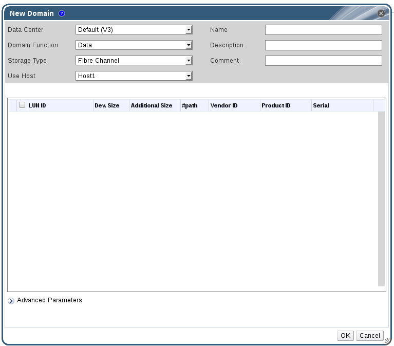
Figure 8.5. Adding FCP Storage
- Use the Data Center drop-down menu to select an FCP data center.If you do not yet have an appropriate FCP data center, select
(none). - Use the drop-down menus to select the Domain Function and the Storage Type. The storage domain types that are not compatible with the chosen data center are not available.
- Select an active host in the Use Host field. If this is not the first data domain in a data center, you must select the data center's SPM host.
Important
All communication to the storage domain is through the selected host and not directly from the Red Hat Virtualization Manager. At least one active host must exist in the system and be attached to the chosen data center. All hosts must have access to the storage device before the storage domain can be configured. - The New Domain window automatically displays known targets with unused LUNs when Data / Fibre Channel is selected as the storage type. Select the LUN ID check box to select all of the available LUNs.
- Optionally, you can configure the advanced parameters.
- Click Advanced Parameters.
- Enter a percentage value into the Warning Low Space Indicator field. If the free space available on the storage domain is below this percentage, warning messages are displayed to the user and logged.
- Enter a GB value into the Critical Space Action Blocker field. If the free space available on the storage domain is below this value, error messages are displayed to the user and logged, and any new action that consumes space, even temporarily, will be blocked.
- Select the Wipe After Delete check box to enable the wipe after delete option. This option can be edited after the domain is created, but doing so will not change the wipe after delete property of disks that already exist.
- Select the Discard After Delete check box to enable the discard after delete option. This option can be edited after the domain is created. This option is only available to block storage domains.
- Click to create the storage domain and close the window.
Locked status while it is being prepared for use. When ready, it is automatically attached to the data center.
8.5.4. Increasing iSCSI or FCP Storage
- Add an existing LUN to the current storage domain.
- Create a new storage domain with new LUNs and add it to an existing datacenter. See Section 8.5.1, “Adding iSCSI Storage”
- Expand the storage domain by resizing the underlying LUNs.
Prerequisites
- The storage domain's status must be
UP. - The LUN must be accessible to all the hosts whose status is
UP, or else the operation will fail and the LUN will not be added to the domain. The hosts themselves, however, will not be affected. If a newly added host, or a host that is coming out of maintenance or aNon Operationalstate, cannot access the LUN, the host's state will beNon Operational.
Procedure 8.9. Increasing an Existing iSCSI or FCP Storage Domain
- Click the Storage resource tab and select an iSCSI or FCP domain.
- Click the button.
- Click Targets > LUNs, and click the expansion button.
- Enter the connection information for the storage server and click to initiate the connection.
- Click LUNs > Targets and select the check box of the newly available LUN.
- Click to add the LUN to the selected storage domain.
Procedure 8.10. Refreshing the LUN Size
- Click the Storage resource tab and select an iSCSI or FCP domain.
- Click the button.
- Click on LUNs > Targets.
- In the Additional Size column, click the button of the LUN to refresh.
- Click to refresh the LUN to indicate the new storage size.
8.5.5. Reusing LUNs
Physical device initialization failed. Please check that the device is empty and accessible by the host.
[ ERROR ] Error creating Volume Group: Failed to initialize physical device: ("[u'/dev/mapper/000000000000000000000000000000000']",)
[ ERROR ] Failed to execute stage 'Misc configuration': Failed to initialize physical device: ("[u'/dev/mapper/000000000000000000000000000000000']",)Procedure 8.11. Clearing the Partition Table from a LUN
Important
- Run the
ddcommand with the ID of the LUN that you want to reuse, the maximum number of bytes to read and write at a time, and the number of input blocks to copy:# dd if=/dev/zero of=/dev/mapper/LUN_ID bs=1M count=200 oflag=direct
8.6. Importing Existing Storage Domains
8.6.1. Overview of Importing Existing Storage Domains
- Data
- Importing an existing data storage domain allows you to access all of the virtual machines and templates that the data storage domain contains. After you import the storage domain, you must manually import virtual machines, floating disk images, and templates into the destination data center. The process for importing the virtual machines and templates that a data storage domain contains is similar to that for an export storage domain. However, because data storage domains contain all the virtual machines and templates in a given data center, importing data storage domains is recommended for data recovery or large-scale migration of virtual machines between data centers or environments.
Important
You can import existing data storage domains that were attached to data centers with a compatibility level of 3.5 or higher. - ISO
- Importing an existing ISO storage domain allows you to access all of the ISO files and virtual diskettes that the ISO storage domain contains. No additional action is required after importing the storage domain to access these resources; you can attach them to virtual machines as required.
- Export
- Importing an existing export storage domain allows you to access all of the virtual machine images and templates that the export storage domain contains. Because export domains are designed for exporting and importing virtual machine images and templates, importing export storage domains is recommended method of migrating small numbers of virtual machines and templates inside an environment or between environments. For information on exporting and importing virtual machines and templates to and from export storage domains, see Exporting and Importing Virtual Machines and Templates in the Virtual Machine Management Guide.
Note
The export storage domain is deprecated. Storage data domains can be unattached from a data center and imported to another data center in the same environment, or in a different environment. Virtual machines, floating virtual disks, and templates can then be uploaded from the imported storage domain to the attached data center.
8.6.2. Importing Storage Domains
Procedure 8.12. Importing a Storage Domain
- Click the Storage resource tab.
- Click .
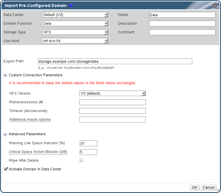
Figure 8.6. The Import Pre-Configured Domain window
- Select the data center to which to attach the storage domain from the Data Center drop-down list.
- Enter a name for the storage domain.
- Select the Domain Function and Storage Type from the appropriate drop-down lists.
- Select a host from the Use host drop-down list.
Important
All communication to the storage domain is through the selected host and not directly from the Red Hat Virtualization Manager. At least one active host must exist in the system and be attached to the chosen data center. All hosts must have access to the storage device before the storage domain can be configured. - Enter the details of the storage domain.
Note
The fields for specifying the details of the storage domain change in accordance with the value you select in the Domain Function / Storage Type list. These options are the same as those available for adding a new storage domain. For more information on these options, see Section 8.1, “Understanding Storage Domains”. - Select the Activate Domain in Data Center check box to activate the storage domain after attaching it to the selected data center.
- Click .
8.6.3. Migrating Storage Domains between Data Centers in the Same Environment
Procedure 8.13. Migrating a Storage Domain between Data Centers in the Same Environment
- Shut down all virtual machines running on the required storage domain.
- Click the Storage resource tab and select the storage domain from the results list.
- Click the Data Center tab in the details pane.
- Click , then click to move the storage domain to maintenance mode.
- Click , then click to detach the storage domain from the source data center.
- Click .
- Select the destination data center and click .
8.6.4. Migrating Storage Domains between Data Centers in Different Environments
Procedure 8.14. Migrating a Storage Domain between Data Centers in Different Environments
- Log in to the Administration Portal of the source environment.
- Shut down all virtual machines running on the required storage domain.
- Click the Storage resource tab and select the storage domain from the results list.
- Click the Data Center tab in the details pane.
- Click , then click to move the storage domain to maintenance mode.
- Click , then click to detach the storage domain from the source data center.
- Click .
- In the Remove Storage(s) window, ensure the Format Domain, i.e. Storage Content will be lost! check box is not selected. This step preserves the data in the storage domain for later use.
- Click to remove the storage domain from the source environment.
- Log in to the Administration Portal of the destination environment.
- Click the Storage resource tab.
- Click .
Figure 8.7. The Import Pre-Configured Domain window
- Select the destination data center from the Data Center drop-down list.
- Enter a name for the storage domain.
- Select the Domain Function and Storage Type from the appropriate drop-down lists.
- Select a host from the Use Host drop-down list.
- Enter the details of the storage domain.
Note
The fields for specifying the details of the storage domain change in accordance with the value you select in the Storage Type drop-down list. These options are the same as those available for adding a new storage domain. For more information on these options, see Section 8.1, “Understanding Storage Domains”. - Select the Activate Domain in Data Center check box to automatically activate the storage domain when it is attached.
- Click .
8.6.5. Importing Virtual Machines from Imported Data Storage Domains
Procedure 8.15. Importing Virtual Machines from an Imported Data Storage Domain
- Click the Storage resource tab.
- Click the imported data storage domain.
- Click the VM Import tab in the details pane.
- Select one or more virtual machines to import.
- Click .
- For each virtual machine in the Import Virtual Machine(s) window, ensure the correct target cluster is selected in the Cluster list.
- Map external virtual machine vNIC profiles to profiles that are present on the target cluster(s):
- Click .
- Select the vNIC profile to use from the Target vNic Profile drop-down list.
- If multiple target clusters are selected in the Import Virtual Machine(s) window, select each target cluster in the Target Cluster drop-down list and ensure the mappings are correct.
- Click .
- If a MAC address conflict is detected, an exclamation mark appears next to the name of the virtual machine. Mouse over the icon to view a tooltip displaying the type of error that occurred.Select the check box to reassign new MAC addresses to all problematic virtual machines. Alternatively, you can select the Reassign check box per virtual machine.
Note
If there are no available addresses to assign, the import operation will fail. However, in the case of MAC addresses that are outside the cluster's MAC address pool range, it is possible to import the virtual machine without reassigning a new MAC address. - Click .
8.6.6. Importing Templates from Imported Data Storage Domains
Procedure 8.16. Importing Templates from an Imported Data Storage Domain
- Click the Storage resource tab.
- Click the imported data storage domain.
- Click the Template Import tab in the details pane.
- Select one or more templates to import.
- Click .
- Select the cluster into which the templates are imported from the Cluster list.
- Click .
8.6.7. Importing a Disk Image from an Imported Storage Domain
Note
Procedure 8.17. Importing a Disk Image
- Select a storage domain that has been imported into the data center.
- In the details pane, click Disk Import.
- Select one or more disk images and click to open the Import Disk(s) window.
- Select the appropriate Disk Profile for each disk.
- Click to import the selected disks.
8.6.8. Importing an Unregistered Disk Image from an Imported Storage Domain
Note
Procedure 8.18. Importing a Disk Image
- Select a storage domain that has been imported into the data center.
- Right-click the storage domain and select Scan Disks so that the Manager can identify unregistered disks.
- In the details pane, click Disk Import.
- Select one or more disk images and click to open the Import Disk(s) window.
- Select the appropriate Disk Profile for each disk.
- Click to import the selected disks.
8.7. Storage Tasks
8.7.1. Populating the ISO Storage Domain
Procedure 8.19. Populating the ISO Storage Domain
- Copy the required ISO image to a temporary directory on the system running Red Hat Virtualization Manager.
- Log in to the system running Red Hat Virtualization Manager as the
rootuser. - Use the
engine-iso-uploadercommand to upload the ISO image. This action will take some time. The amount of time varies depending on the size of the image being uploaded and available network bandwidth.Example 8.1. ISO Uploader Usage
In this example the ISO imageRHEL6.isois uploaded to the ISO domain calledISODomainusing NFS. The command will prompt for an administrative user name and password. The user name must be provided in the form user name@domain.#
engine-iso-uploader--iso-domain=ISODomainuploadRHEL6.iso
8.7.2. Moving Storage Domains to Maintenance Mode
Important
Procedure 8.20. Moving storage domains to maintenance mode
- Shut down all the virtual machines running on the storage domain.
- Click the Storage resource tab and select a storage domain.
- Click the Data Centers tab in the details pane.
- Click to open the Storage Domain maintenance confirmation window.
- Click to initiate maintenance mode. The storage domain is deactivated and has an
Inactivestatus in the results list.
Note
8.7.3. Editing Storage Domains
- Active: When the storage domain is in an active state, the Name, Description, Comment, Warning Low Space Indicator (%), Critical Space Action Blocker (GB), Wipe After Delete, and Discard After Delete fields can be edited. The Name field can only be edited while the storage domain is active. All other fields can also be edited while the storage domain is inactive.
- Inactive: When the storage domain is in maintenance mode or unattached, thus in an inactive state, you can edit all fields except Name, Data Center, Domain Function, Storage Type, and Format. The storage domain must be inactive to edit storage connections, mount options, and other advanced parameters. This is only supported for NFS, POSIX, and Local storage types.
Note
iSCSI storage connections cannot be edited via the Administration Portal, but can be edited via the REST API. See Updating an iSCSI Storage Connection in the REST API Guide.
Procedure 8.21. Editing an Active Storage Domain
- Click the Storage resource tab and select a storage domain.
- Click .
- Edit the available fields as required.
- Click .
Procedure 8.22. Editing an Inactive Storage Domain
- Click the Storage resource tab and select a storage domain.
- If the storage domain is active, click the Data Center tab in the details pane and click .
- Click .
- Edit the storage path and other details as required. The new connection details must be of the same storage type as the original connection.
- Click .
- Click the Data Center tab in the details pane and click .
8.7.4. Updating OVFs
Procedure 8.23. Updating OVFs
- Use the Storage resource tab, tree mode, or the search function to find and select the appropriate storage domain in the results list.
- Right-click the storage domain and select Update OVFs.
8.7.5. Activating Storage Domains from Maintenance Mode
- Click the Storage resource tab and select an inactive storage domain in the results list.
- Click the Data Centers tab in the details pane.
- Select the appropriate storage domain and click .
Important
If you attempt to activate the ISO domain before activating the data domain, an error message displays and the domain is not activated.
8.7.6. Removing a Storage Domain
Procedure 8.24. Removing a Storage Domain
- Click the Storage resource tab and select the appropriate storage domain in the results list.
- Move the domain into maintenance mode to deactivate it.
- Detach the domain from the data center.
- Click to open the Remove Storage confirmation window.
- Select a host from the list.
- Click to remove the storage domain and close the window.
8.7.7. Destroying a Storage Domain
Procedure 8.25. Destroying a Storage Domain
- Use the Storage resource tab, tree mode, or the search function to find and select the appropriate storage domain in the results list.
- Right-click the storage domain and select to open the Destroy Storage Domain confirmation window.
- Select the Approve operation check box and click to destroy the storage domain and close the window.
8.7.8. Detaching a Storage Domain from a Data Center
Procedure 8.26. Detaching a Storage Domain from the Data Center
- Click the Storage resource tab, and select a storage domain from the results list.
- Click the Data Centers tab in the details pane and select the storage domain.
- Click to open the Maintenance Storage Domain(s) confirmation window.
- Click to initiate maintenance mode.
- Click to open the Detach Storage confirmation window.
- Click to detach the storage domain.
8.7.9. Attaching a Storage Domain to a Data Center
Procedure 8.27. Attaching a Storage Domain to a Data Center
- Click the Storage resource tab, and select a storage domain from the results list.
- Click the Data Centers tab in the details pane.
- Click to open the Attach to Data Center window.
- Select the radio button of the appropriate data center.
- Click to attach the storage domain.
8.7.10. Disk Profiles
8.7.10.1. Creating a Disk Profile
Procedure 8.28. Creating a Disk Profile
- Click the Storage resource tab and select a data storage domain.
- Click the Disk Profiles sub tab in the details pane.
- Click .
- Enter a name for the disk profile in the Name field.
- Enter a description for the disk profile in the Description field.
- Select the quality of service to apply to the disk profile from the QoS list.
- Click .
8.7.10.2. Removing a Disk Profile
Procedure 8.29. Removing a Disk Profile
- Click the Storage resource tab and select a data storage domain.
- Click the Disk Profiles sub tab in the details pane.
- Select the disk profile to remove.
- Click .
- Click .
8.7.11. Viewing the Health Status of a Storage Domain
- OK: No icon
- Info:
- Warning:
- Error:
- Failure:
GET request on a storage domain will include the external_status element, which contains the health status.
events collection. For more information, see Adding Events in the REST API Guide.
8.7.12. Setting Discard After Delete for a Storage Domain
blkdiscard command is called on a logical volume when it is removed and the underlying storage is notified that the blocks are free. The storage array can use the freed space and allocate it when requested. Discard After Delete only works on block storage. The flag is not available on the Red Hat Virtualization Manager for file storage, for example NFS.
Restrictions:
- Discard After Delete is only available on block storage domains, such as iSCSI or Fibre Channel.
- The underlying storage must support
Discard.
8.8. Storage and Permissions
8.8.1. Managing System Permissions for a Storage Domain
- Edit the configuration of the storage domain.
- Move the storage domain into maintenance mode.
- Remove the storage domain.
Note
8.8.2. Storage Administrator Roles Explained
The table below describes the administrator roles and privileges applicable to storage domain administration.
| Role | Privileges | Notes |
|---|---|---|
| StorageAdmin | Storage Administrator | Can create, delete, configure and manage a specific storage domain. |
| GlusterAdmin | Gluster Storage Administrator | Can create, delete, configure and manage Gluster storage volumes. |
8.8.3. Assigning an Administrator or User Role to a Resource
Procedure 8.30. Assigning a Role to a Resource
- Use the resource tabs, tree mode, or the search function to find and select the resource in the results list.
- Click the tab in the details pane to list the assigned users, the user's role, and the inherited permissions for the selected resource.
- Click .
- Enter the name or user name of an existing user into the Search text box and click . Select a user from the resulting list of possible matches.
- Select a role from the Role to Assign: drop-down list.
- Click .
8.8.4. Removing an Administrator or User Role from a Resource
Procedure 8.31. Removing a Role from a Resource
- Use the resource tabs, tree mode, or the search function to find and select the resource in the results list.
- Click the tab in the details pane to list the assigned users, the user's role, and the inherited permissions for the selected resource.
- Select the user to remove from the resource.
- Click . The Remove Permission window opens to confirm permissions removal.
- Click .
Chapter 9. Working with Red Hat Gluster Storage
9.1. Red Hat Gluster Storage Nodes
9.1.1. Adding Red Hat Gluster Storage Nodes
Procedure 9.1. Adding a Red Hat Gluster Storage Node
- Click the Hosts resource tab to list the hosts in the results list.
- Click to open the New Host window.
- Use the drop-down menus to select the Data Center and Host Cluster for the Red Hat Gluster Storage node.
- Enter the Name, Address, and SSH Port of the Red Hat Gluster Storage node.
- Select an authentication method to use with the Red Hat Gluster Storage node.
- Enter the root user's password to use password authentication.
- Copy the key displayed in the SSH PublicKey field to
/root/.ssh/authorized_keyson the Red Hat Gluster Storage node to use public key authentication.
- Click to add the node and close the window.
9.1.2. Removing a Red Hat Gluster Storage Node
Procedure 9.2. Removing a Red Hat Gluster Storage Node
- Use the Hosts resource tab, tree mode, or the search function to find and select the Red Hat Gluster Storage node in the results list.
- Click → to open the Maintenance Host(s) confirmation window.
- Click to move the host to maintenance mode.
- Click to open the Remove Host(s) confirmation window.
- Select the Force Remove check box if the node has volume bricks on it, or if the node is non-responsive.
- Click to remove the node and close the window.
9.2. Using Red Hat Gluster Storage as a Storage Domain
9.2.1. Introduction to Red Hat Gluster Storage (GlusterFS) Volumes
9.2.2. Gluster Storage Terminology
|
Term
|
Definition
|
|---|---|
|
Brick
|
A brick is the GlusterFS basic unit of storage, represented by an export directory on a server in the trusted storage pool. A Brick is expressed by combining a server with an export directory in the following format:
SERVER:EXPORT
For example:
myhostname:/exports/myexportdir/
|
|
Block Storage
|
Block special files or block devices correspond to devices through which the system moves data in the form of blocks. These device nodes often represent addressable devices such as hard disks, CD-ROM drives, or memory-regions. Red Hat Gluster Storage supports XFS file system with extended attributes.
|
|
Cluster
|
A trusted pool of linked computers, working together closely thus in many respects forming a single computer. In Red Hat Gluster Storage terminology a cluster is called a trusted storage pool.
|
|
Client
|
The machine that mounts the volume (this may also be a server).
|
|
Distributed File System
|
A file system that allows multiple clients to concurrently access data spread across multiple servers/bricks in a trusted storage pool. Data sharing among multiple locations is fundamental to all distributed file systems.
|
|
Geo-Replication
|
Geo-replication provides a continuous, asynchronous, and incremental replication service from site to another over Local Area Networks (LAN), Wide Area Network (WAN), and across the Internet.
|
|
glusterd
|
The Gluster management daemon that needs to run on all servers in the trusted storage pool.
|
|
Metadata
|
Metadata is data providing information about one or more other pieces of data.
|
|
N-way Replication
|
Local synchronous data replication typically deployed across campus or Amazon Web Services Availability Zones.
|
|
Namespace
|
Namespace is an abstract container or environment created to hold a logical grouping of unique identifiers or symbols. Each Red Hat Gluster Storage trusted storage pool exposes a single namespace as a POSIX mount point that contains every file in the trusted storage pool.
|
|
POSIX
|
Portable Operating System Interface (for Unix) is the name of a family of related standards specified by the IEEE to define the application programming interface (API), along with shell and utilities interfaces for software compatible with variants of the UNIX operating system. Red Hat Gluster Storage exports a fully POSIX compatible file system.
|
|
RAID
|
Redundant Array of Inexpensive Disks (RAID) is a technology that provides increased storage reliability through redundancy, combining multiple low-cost, less-reliable disk drives components into a logical unit where all drives in the array are interdependent.
|
|
RRDNS
|
Round Robin Domain Name Service (RRDNS) is a method to distribute load across application servers. RRDNS is implemented by creating multiple A records with the same name and different IP addresses in the zone file of a DNS server.
|
|
Server
|
The machine (virtual or bare-metal) which hosts the actual file system in which data will be stored.
|
|
Scale-Up Storage
|
Increases the capacity of the storage device, but only in a single dimension. An example might be adding additional disk capacity to a single computer in a trusted storage pool.
|
|
Scale-Out Storage
|
Increases the capability of a storage device in multiple dimensions. For example adding a server to a trusted storage pool increases CPU, disk capacity, and throughput for the trusted storage pool.
|
|
Subvolume
|
A subvolume is a brick after being processed by at least one translator.
|
|
Translator
|
A translator connects to one or more subvolumes, does something with them, and offers a subvolume connection.
|
|
Trusted Storage Pool
|
A storage pool is a trusted network of storage servers. When you start the first server, the storage pool consists of that server alone.
|
|
User Space
|
Applications running in user space do not directly interact with hardware, instead using the kernel to moderate access. User Space applications are generally more portable than applications in kernel space. Gluster is a user space application.
|
|
Virtual File System (VFS)
|
VFS is a kernel software layer that handles all system calls related to the standard Linux file system. It provides a common interface to several kinds of file systems.
|
|
Volume File
|
The volume file is a configuration file used by GlusterFS process. The volume file will usually be located at:
/var/lib/glusterd/vols/VOLNAME.
|
|
Volume
|
A volume is a logical collection of bricks. Most of the Gluster management operations happen on the volume.
|
9.2.3. Attaching a Red Hat Gluster Storage Volume as a Storage Domain
rh-common-rpms repository on the Customer Portal.
- To set up a Red Hat Gluster Storage node, see the Red Hat Gluster Storage Installation Guide.
- To check the compatibility of Red Hat Gluster Storage nodes within a cluster and the compatibility of Red Hat Gluster Storage servers with Red Hat Virtualization, see Red Hat Gluster Storage Version Compatibility and Support.
- To prepare a host to be used with Red Hat Storage Gluster volumes, see the Configuring Red Hat Virtualization with Red Hat Gluster Storage Guide.
- To set up Red Hat Gluster Storage in a Red Hat Hyperconverged Infrastructure deployment, see Deploying Red Hat Hyperconverged Infrastructure.
- To geo-replicate data from one Red Hat Gluster Storage volume to another as a backup for disaster recovery, see Configure Disaster Recovery using Geo-replication.
- To restore a Red Hat Gluster Storage volume from a geo-replicated backup, see Restoring a Volume from a Geo-replicated Backup.
Procedure 9.3. Adding a Red Hat Gluster Storage Volume as a Storage Domain
- Click the Storage resource tab to list the existing storage domains in the results list.
- Click to open the New Domain window.

Figure 9.1. Red Hat Gluster Storage
- Enter the Name for the storage domain.
- Select the Data Center to be associated with the storage domain.
- Select
Datafrom the Domain Function drop-down list. - Select
GlusterFSfrom the Storage Type drop-down list. - Select a host from the Use Host drop-down list. Only hosts within the selected data center will be listed. To mount the volume, the host that you select must have the glusterfs and glusterfs-fuse packages installed.
- In the Path field, enter the IP address or FQDN of the Red Hat Gluster Storage server and the volume name separated by a colon.
- Enter additional Mount Options, as you would normally provide them to the
mountcommand using the-oargument. The mount options should be provided in a comma-separated list. Seeman mountfor a list of valid mount options. - Optionally, you can configure the advanced parameters.
- Click Advanced Parameters.
- Enter a percentage value into the Warning Low Space Indicator field. If the free space available on the storage domain is below this percentage, warning messages are displayed to the user and logged.
- Enter a GB value into the Critical Space Action Blocker field. If the free space available on the storage domain is below this value, error messages are displayed to the user and logged, and any new action that consumes space, even temporarily, will be blocked.
- Select the Wipe After Delete check box to enable the wipe after delete option. This option can be edited after the domain is created, but doing so will not change the wipe after delete property of disks that already exist.
- Click to mount the volume as a storage domain and close the window.
9.2.4. Creating a Storage Volume
Important
Procedure 9.4. Creating A Storage Volume
- Click the Volumes resource tab to list existing volumes in the results list.
- Click to open the New Volume window.
- Use the drop-down menus to select the Data Center and Volume Cluster.
- Enter the Name of the volume.
- Use the drop-down menu to select the Type of the volume.
- If active, select the appropriate Transport Type check box.
- Click the button to select bricks to add to the volume. Bricks must be created externally on the Red Hat Gluster Storage nodes.
- If active, use the Gluster, NFS, and CIFS check boxes to select the appropriate access protocols used for the volume.
- Enter the volume access control as a comma-separated list of IP addresses or hostnames in the Allow Access From field.You can use the * wildcard to specify ranges of IP addresses or hostnames.
- Select the Optimize for Virt Store option to set the parameters to optimize your volume for virtual machine storage. Select this if you intend to use this volume as a storage domain.
- Click to create the volume. The new volume is added and displays on the Volume tab.
9.2.5. Adding Bricks to a Volume
You can expand your volumes by adding new bricks. You need to add at least one brick to a distributed volume, multiples of two bricks to replicated volumes, and multiples of four bricks to striped volumes when expanding your storage space.
Procedure 9.5. Adding Bricks to a Volume
- On the Volumes tab on the navigation pane, select the volume to which you want to add bricks.
- Click the tab from the Details pane.
- Click to open the Add Bricks window.
- Use the Server drop-down menu to select the server on which the brick resides.
- Enter the path of the Brick Directory. The directory must already exist.
- Click . The brick appears in the list of bricks in the volume, with server addresses and brick directory names.
- Click .
The new bricks are added to the volume and the bricks display in the volume's Bricks tab.
9.2.6. Explanation of Settings in the Add Bricks Window
|
Field Name
|
Description
|
|---|---|
|
Volume Type
|
Displays the type of volume. This field cannot be changed; it was set when you created the volume.
|
|
Server
|
The server where the bricks are hosted.
|
| Brick Directory |
The brick directory or mountpoint.
|
9.2.7. Optimizing Red Hat Gluster Storage Volumes to Store Virtual Machine Images
Important
virt. This sets the cluster.quorum-type parameter to auto, and the cluster.server-quorum-type parameter to server.
# gluster volume set VOLUME_NAME group virt
# gluster volume info VOLUME_NAME
9.2.8. Starting Volumes
After a volume has been created or an existing volume has been stopped, it needs to be started before it can be used.
Procedure 9.6. Starting Volumes
- In the Volumes tab, select the volume to be started.You can select multiple volumes to start by using
ShiftorCtrlkey. - Click the button.
Up.
You can now use your volume for virtual machine storage.
9.2.9. Tuning Volumes
Tuning volumes allows you to affect their performance. To tune volumes, you add options to them.
Procedure 9.7. Tuning Volumes
- Click the Volumes tab.A list of volumes displays.
- Select the volume that you want to tune, and click the tab from the Details pane.The Volume Options tab displays a list of options set for the volume.
- Click to set an option. The Add Option dialog box displays. Select the Option Key from the drop down list and enter the option value.
- Click .The option is set and displays in the Volume Options tab.
You have tuned the options for your storage volume.
9.2.10. Editing Volume Options
You have tuned your volume by adding options to it. You can change the options for your storage volume.
Procedure 9.8. Editing Volume Options
- Click the Volumes tab.A list of volumes displays.
- Select the volume that you want to edit, and click the Volume Options tab from the Details pane.The Volume Options tab displays a list of options set for the volume.
- Select the option you want to edit. Click . The Edit Option dialog box displays. Enter a new value for the option.
- Click .The edited option displays in the Volume Options tab.
You have changed the options on your volume.
9.2.11. Reset Volume Options
You can reset options to revert them to their default values.
- Click the Volumes tab.A list of volumes displays.
- Select the volume and click the tab from the Details pane.The Volume Options tab displays a list of options set for the volume.
- Select the option you want to reset. Click . A dialog box displays, prompting to confirm the reset option.
- Click .The selected option is reset.
Note
You have reset volume options to default.
9.2.12. Removing Bricks from a Volume
You can shrink volumes, as needed, while the cluster is online and available. For example, you might need to remove a brick that has become inaccessible in a distributed volume due to hardware or network failure.
Procedure 9.9. Removing Bricks from a Volume
- On the Volumes tab on the navigation pane, select the volume from which you wish to remove bricks.
- Click the tab from the Details pane.
- Select the bricks you wish to remove. Click .
- A window opens, prompting to confirm the deletion. Click OK to confirm.
The bricks are removed from the volume.
9.2.13. Stopping Red Hat Gluster Storage Volumes
Procedure 9.10. Stopping Volumes
- In the Volumes tab, select the volume to be stopped.You can select multiple volumes to stop by using
ShiftorCtrlkey. - Click .
9.2.14. Deleting Red Hat Gluster Storage Volumes
- In the Volumes tab, select the volume to be deleted.
- Click . A dialog box displays, prompting to confirm the deletion. Click .
9.2.15. Rebalancing Volumes
If a volume has been expanded or shrunk by adding or removing bricks to or from that volume, the data on the volume must be rebalanced amongst the servers.
Procedure 9.11. Rebalancing a Volume
- Click the Volumes tab.A list of volumes displays.
- Select the volume to rebalance.
- Click Rebalance.
The selected volume is rebalanced.
9.3. Clusters and Gluster Hooks
9.3.1. Managing Gluster Hooks
- View a list of hooks available in the hosts.
- View the content and status of hooks.
- Enable or disable hooks.
- Resolve hook conflicts.
9.3.2. Listing Hooks
List the Gluster hooks in your environment.
Procedure 9.12. Listing a Hook
- Use the Cluster resource tab, tree mode, or the search function to find and select a cluster in the results list.
- Select the Gluster Hooks sub-tab to list the hooks in the details pane.
You have listed the Gluster hooks in your environment.
9.3.3. Viewing the Content of Hooks
View the content of a Gluster hook in your environment.
Procedure 9.13. Viewing the Content of a Hook
- Use the Cluster resource tab, tree mode, or the search function to find and select a cluster in the results list.
- Select the Gluster Hooks sub-tab to list the hooks in the details pane.
- Select a hook with content type Text and click the button to open the Hook Content window.
You have viewed the content of a hook in your environment.
9.3.4. Enabling or Disabling Hooks
Toggle the activity of a Gluster hook by enabling or disabling it.
Procedure 9.14. Enabling or Disabling a Hook
- Use the Cluster resource tab, tree mode, or the search function to find and select a cluster in the results list.
- Select the Gluster Hooks sub-tab to list the hooks in the details pane.
- Select a hook and click one of the or buttons. The hook is enabled or disabled on all nodes of the cluster.
You have toggled the activity of a Gluster hook in your environment.
9.3.5. Refreshing Hooks
By default, the Manager checks the status of installed hooks on the engine and on all servers in the cluster and detects new hooks by running a periodic job every hour. You can refresh hooks manually by clicking the Sync button.
Procedure 9.15. Refreshing a Hook
- Use the Cluster resource tab, tree mode, or the search function to find and select a cluster in the results list.
- Select the Gluster Hooks sub-tab to list the hooks in the details pane.
- Click the button.
The hooks are synchronized and updated in the details pane.
9.3.6. Resolving Conflicts
- Content Conflict - the content of the hook is different across servers.
- Missing Conflict - one or more servers of the cluster do not have the hook.
- Status Conflict - the status of the hook is different across servers.
- Multiple Conflicts - a hook has a combination of two or more of the aforementioned conflicts.
9.3.7. Resolving Content Conflicts
A hook that is not consistent across the servers and engine will be flagged as having a conflict. To resolve the conflict, you must select a version of the hook to be copied across all servers and the engine.
Procedure 9.16. Resolving a Content Conflict
- Use the Cluster resource tab, tree mode, or the search function to find and select a cluster in the results list.
- Select the Gluster Hooks sub-tab to list the hooks in the details pane.
- Select the conflicting hook and click the button to open the Resolve Conflicts window.
- Select the engine or a server from the list of sources to view the content of that hook and establish which version of the hook to copy.
Note
The content of the hook will be overwritten in all servers and in the engine. - Use the Use content from drop-down menu to select the preferred server or the engine.
- Click OK to resolve the conflict and close the window.
The hook from the selected server is copied across all servers and the engine to be consistent across the environment.
9.3.8. Resolving Missing Hook Conflicts
A hook that is not present on all the servers and the engine will be flagged as having a conflict. To resolve the conflict, either select a version of the hook to be copied across all servers and the engine, or remove the missing hook entirely.
Procedure 9.17. Resolving a Missing Hook Conflict
- Use the Cluster resource tab, tree mode, or the search function to find and select a cluster in the results list.
- Select the Gluster Hooks sub-tab to list the hooks in the details pane.
- Select the conflicting hook and click the button to open the Resolve Conflicts window.
- Select any source with a status of Enabled to view the content of the hook.
- Select the appropriate radio button, either Copy the hook to all the servers or Remove the missing hook. The latter will remove the hook from the engine and all servers.
- Click OK to resolve the conflict and close the window.
Depending on your chosen resolution, the hook has either been removed from the environment entirely, or has been copied across all servers and the engine to be consistent across the environment.
9.3.9. Resolving Status Conflicts
A hook that does not have a consistent status across the servers and engine will be flagged as having a conflict. To resolve the conflict, select a status to be enforced across all servers in the environment.
Procedure 9.18. Resolving a Status Conflict
- Use the Cluster resource tab, tree mode, or the search function to find and select a cluster in the results list.
- Select the Gluster Hooks sub-tab to list the hooks in the details pane.
- Select the conflicting hook and click the button to open the Resolve Conflicts window.
- Set Hook Status to Enable or Disable.
- Click OK to resolve the conflict and close the window.
The selected status for the hook is enforced across the engine and the servers to be consistent across the environment.
9.3.10. Resolving Multiple Conflicts
A hook may have a combination of two or more conflicts. These can all be resolved concurrently or independently through the Resolve Conflicts window. This procedure will resolve all conflicts for the hook so that it is consistent across the engine and all servers in the environment.
Procedure 9.19. Resolving Multiple Conflicts
- Use the Cluster resource tab, tree mode, or the search function to find and select a cluster in the results list.
- Select the Gluster Hooks sub-tab to list the hooks in the details pane.
- Select the conflicting hook and click the button to open the Resolve Conflicts window.
- Choose a resolution to each of the affecting conflicts, as per the appropriate procedure.
- Click OK to resolve the conflicts and close the window.
You have resolved all of the conflicts so that the hook is consistent across the engine and all servers.
9.3.11. Managing Gluster Sync
Note
Chapter 10. Pools
10.1. Introduction to Virtual Machine Pools
Note
10.2. Virtual Machine Pool Tasks
10.2.1. Creating a Virtual Machine Pool
Procedure 10.1. Creating a Virtual Machine Pool
- Click the Pools tab.
- Click the button to open the New Pool window.
- Use the drop down-list to select the Cluster or use the selected default.
- Use the Template drop-down menu to select the required template and version or use the selected default. A template provides standard settings for all the virtual machines in the pool.
- Use the Operating System drop-down list to select an Operating System or use the default provided by the template.
- Use the Optimized for drop-down list to optimize virtual machines for either Desktop use or Server use.
- Enter a Name and Description, any Comments, and the Number of VMs for the pool.
- Enter the number of virtual machines to be prestarted in the Prestarted VMs field.
- Select the Maximum number of VMs per user that a single user is allowed to run in a session. The minimum is one.
- Select the Delete Protection check box to enable delete protection.
- Optionally, click the Show Advanced Options button and perform the following steps:
- Click the Type tab:
- Select a Pool Type:
- Manual - The administrator is responsible for explicitly returning the virtual machine to the pool.
- Automatic - The virtual machine is automatically returned to the virtual machine pool.
- Select the Stateful Pool check box to ensure that virtual machines are started in a stateful mode. This means that changes made by a previous user will persist on a virtual machine.
- Click the Console tab:
- Select the Override SPICE Proxy check box.
- In the Overridden SPICE proxy address text field, specify the address of a SPICE proxy to override the global SPICE proxy.
- Click .
10.2.2. Explanation of Settings and Controls in the New Pool and Edit Pool Windows
10.2.2.1. New Pool and Edit Pool General Settings Explained
|
Field Name
|
Description
|
|---|---|
|
Template
|
The template and template sub version on which the virtual machine pool is based. If you create a pool based on the
latest sub version of a template, all virtual machines in the pool, when rebooted, will automatically receive the latest template version. For more information on configuring templates for virtual machines see Virtual Machine General Settings Explained and Explanation of Settings in the New Template and Edit Template Windows in the Virtual Machine Management Guide.
|
|
Description
|
A meaningful description of the virtual machine pool.
|
|
Comment
|
A field for adding plain text human-readable comments regarding the virtual machine pool.
|
|
Prestarted VMs
|
Allows you to specify the number of virtual machines in the virtual machine pool that will be started before they are taken and kept in that state to be taken by users. The value of this field must be between
0 and the total number of virtual machines in the virtual machine pool.
|
|
Number of VMs/Increase number of VMs in pool by
|
Allows you to specify the number of virtual machines to be created and made available in the virtual machine pool. In the edit window it allows you to increase the number of virtual machines in the virtual machine pool by the specified number. By default, the maximum number of virtual machines you can create in a pool is 1000. This value can be configured using the
MaxVmsInPool key of the engine-config command.
|
|
Maximum number of VMs per user
|
Allows you to specify the maximum number of virtual machines a single user can take from the virtual machine pool at any one time. The value of this field must be between
1 and 32,767.
|
|
Delete Protection
|
Allows you to prevent the virtual machines in the pool from being deleted.
|
10.2.2.2. New and Edit Pool Type Settings Explained
|
Field Name
|
Description
|
|---|---|
|
Pool Type
|
This drop-down menu allows you to specify the type of the virtual machine pool. The following options are available:
|
|
Stateful Pool
|
Specify whether the state of virtual machines in the pool is preserved when a virtual machine is passed to a different user. This means that changes made by a previous user will persist on the virtual machine.
|
10.2.2.3. New Pool and Edit Pool Console Settings Explained
|
Field Name
|
Description
|
|---|---|
|
Override SPICE proxy
|
Select this check box to enable overriding the SPICE proxy defined in global configuration. This feature is useful in a case where the user (who is, for example, connecting via the User Portal) is outside of the network where the hosts reside.
|
|
Overridden SPICE proxy address
|
The proxy by which the SPICE client will connect to virtual machines. This proxy overrides both the global SPICE proxy defined for the Red Hat Virtualization environment and the SPICE proxy defined for the cluster to which the virtual machine pool belongs, if any. The address must be in the following format:
protocol://[host]:[port] |
10.2.2.4. Virtual Machine Pool Host Settings Explained
|
Field Name
|
Sub-element
|
Description
|
|---|---|---|
|
Start Running On
|
Defines the preferred host on which the virtual machine is to run. Select either:
| |
|
Migration Options
|
Migration mode
|
Defines options to run and migrate the virtual machine. If the options here are not used, the virtual machine will run or migrate according to its cluster's policy.
|
|
Use custom migration policy
|
Defines the migration convergence policy. If the check box is left unselected, the host determines the policy.
| |
|
Use custom migration downtime
|
This check box allows you to specify the maximum number of milliseconds the virtual machine can be down during live migration. Configure different maximum downtimes for each virtual machine according to its workload and SLA requirements. Enter
0 to use the VDSM default value.
| |
|
Auto Converge migrations
|
Only activated with Legacy migration policy. Allows you to set whether auto-convergence is used during live migration of the virtual machine. Large virtual machines with high workloads can dirty memory more quickly than the transfer rate achieved during live migration, and prevent the migration from converging. Auto-convergence capabilities in QEMU allow you to force convergence of virtual machine migrations. QEMU automatically detects a lack of convergence and triggers a throttle-down of the vCPUs on the virtual machine. Auto-convergence is disabled globally by default.
| |
|
Enable migration compression
|
Only activated with Legacy migration policy. The option allows you to set whether migration compression is used during live migration of the virtual machine. This feature uses Xor Binary Zero Run-Length-Encoding to reduce virtual machine downtime and total live migration time for virtual machines running memory write-intensive workloads or for any application with a sparse memory update pattern. Migration compression is disabled globally by default.
| |
|
Pass-Through Host CPU
|
This check box allows virtual machines to take advantage of the features of the physical CPU of the host on which they are situated. This option can only be enabled when Do not allow migration is selected.
| |
|
Configure NUMA
|
NUMA Node Count
|
The number of virtual NUMA nodes to assign to the virtual machine. If the Tune Mode is Preferred, this value must be set to
1.
|
|
Tune Mode
|
The method used to allocate memory.
| |
| |
Opens the NUMA Topology window. This window shows the host's total CPUs, memory, and NUMA nodes, and the virtual machine's virtual NUMA nodes. Pin virtual NUMA nodes to host NUMA nodes by clicking and dragging each vNUMA from the box on the right to a NUMA node on the left.
|
10.2.2.5. New Pool and Edit Pool Resource Allocation Settings Explained
|
Field Name
|
Sub-element
|
Description
|
|---|---|---|
|
Disk Allocation
| ||
|
Auto select target
|
Select this check box to automatically select the storage domain that has the most free space. The Target and Profile fields are disabled.
| |
|
Format
|
This field is read-only and always displays QCOW2 unless the storage domain type is OpenStack Volume (Cinder), in which case the format is Raw.
|
10.2.3. Editing a Virtual Machine Pool
10.2.3.1. Editing a Virtual Machine Pool
Note
Procedure 10.2. Editing a Virtual Machine Pool
- Click the Pools resource tab, and select a virtual machine pool from the results list.
- Click to open the Edit Pool window.
- Edit the properties of the virtual machine pool.
- Click .
10.2.3.2. Prestarting Virtual Machines in a Pool
Procedure 10.3. Prestarting Virtual Machines in a Pool
- Use the Pools resource tab, tree mode, or the search function to find and select the virtual machine pool in the results list.
- Click to open the Edit Pool window.
- Enter the number of virtual machines to be prestarted in the Prestarted VMs field.
- Select the Pool tab. Ensure Pool Type is set to Automatic.
- Click .
10.2.3.3. Adding Virtual Machines to a Virtual Machine Pool
Procedure 10.4. Adding Virtual Machines to a Virtual Machine Pool
- Use the Pools resource tab, tree mode, or the search function to find and select the virtual machine pool in the results list.
- Click to open the Edit Pool window.
- Enter the number of additional virtual machines to add in the Increase number of VMs in pool by field.
- Click .
10.2.3.4. Detaching Virtual Machines from a Virtual Machine Pool
Procedure 10.5. Detaching Virtual Machines from a Virtual Machine Pool
- Use the Pools resource tab, tree mode, or the search function to find and select the virtual machine pool in the results list.
- Ensure the virtual machine has a status of
Downbecause you cannot detach a running virtual machine.Click the Virtual Machines tab in the details pane to list the virtual machines in the pool. - Select one or more virtual machines and click to open the Detach Virtual Machine(s) confirmation window.
- Click to detach the virtual machine from the pool.
Note
10.2.4. Removing a Virtual Machine Pool
Procedure 10.6. Removing a Virtual Machine Pool
- Use the Pools resource tab, tree mode, or the search function to find and select the virtual machine pool in the results list.
- Click to open the Remove Pool(s) confirmation window.
- Click to remove the pool.
10.3. Pools and Permissions
10.3.1. Managing System Permissions for a Virtual Machine Pool
- Create, edit, and remove pools.
- Add and detach virtual machines from the pool.
Note
10.3.2. Virtual Machine Pool Administrator Roles Explained
The table below describes the administrator roles and privileges applicable to pool administration.
| Role | Privileges | Notes |
|---|---|---|
| VmPoolAdmin | System Administrator role of a virtual pool. | Can create, delete, and configure a virtual pool, assign and remove virtual pool users, and perform basic operations on a virtual machine. |
| ClusterAdmin | Cluster Administrator | Can use, create, delete, manage all virtual machine pools in a specific cluster. |
10.3.3. Assigning an Administrator or User Role to a Resource
Procedure 10.7. Assigning a Role to a Resource
- Use the resource tabs, tree mode, or the search function to find and select the resource in the results list.
- Click the tab in the details pane to list the assigned users, the user's role, and the inherited permissions for the selected resource.
- Click .
- Enter the name or user name of an existing user into the Search text box and click . Select a user from the resulting list of possible matches.
- Select a role from the Role to Assign: drop-down list.
- Click .
10.3.4. Removing an Administrator or User Role from a Resource
Procedure 10.8. Removing a Role from a Resource
- Use the resource tabs, tree mode, or the search function to find and select the resource in the results list.
- Click the tab in the details pane to list the assigned users, the user's role, and the inherited permissions for the selected resource.
- Select the user to remove from the resource.
- Click . The Remove Permission window opens to confirm permissions removal.
- Click .
10.4. Trusted Compute Pools
- Configuring the Manager to communicate with an OpenAttestation server.
- Creating a trusted cluster that can only run trusted hosts.
- Adding trusted hosts to the trusted cluster. Hosts must be running the OpenAttestation agent to be verified as trusted by the OpenAttestation sever.
10.4.1. Connecting an OpenAttestation Server to the Manager
engine-config to add the OpenAttestation server's FQDN or IP address:
# engine-config -s AttestationServer=attestationserver.example.com
|
Option
|
Default Value
|
Description
|
|---|---|---|
|
AttestationServer
|
oat-server
|
The FQDN or IP address of the OpenAttestation server. This must be set for the Manager to communicate with the OpenAttestation server.
|
|
AttestationPort
|
8443
|
The port used by the OpenAttestation server to communicate with the Manager.
|
|
AttestationTruststore
|
TrustStore.jks
|
The trust store used for securing communication with the OpenAttestation server.
|
|
AttestationTruststorePass
|
password
|
The password used to access the trust store.
|
|
AttestationFirstStageSize
|
10
|
Used for quick initialization. Changing this value without good reason is not recommended.
|
|
SecureConnectionWithOATServers
|
true
|
Enables or disables secure communication with OpenAttestation servers.
|
|
PollUri
|
AttestationService/resources/PollHosts
|
The URI used for accessing the OpenAttestation service.
|
10.4.2. Creating a Trusted Cluster
Procedure 10.9. Creating a Trusted Cluster
- Select the Clusters tab.
- Click .
- Enter a Name for the cluster.
- Select the Enable Virt Service radio button.
- In the Scheduling Policy tab, select the Enable Trusted Service check box.
- Click .
10.4.3. Adding a Trusted Host
- Intel TXT is enabled in the BIOS.
- The OpenAttestation agent is installed and running.
- Software running on the host matches the OpenAttestation server's White List database.
Procedure 10.10. Adding a Trusted Host
- Select the Hosts tab.
- Click .
- Select a trusted cluster from the Host Cluster drop-down list.
- Enter a Name for the host.
- Enter the Address of the host.
- Enter the host's root Password.
- Click .
Non Operational state and should be removed from the trusted cluster.
Chapter 11. Virtual Disks
11.1. Understanding Virtual Machine Storage
kpartx, vgscan, vgchange or mount to investigate the virtual machine's processes or problems.
11.2. Understanding Virtual Disks
- PreallocatedA preallocated virtual disk allocates all the storage required for a virtual machine up front. For example, a 20 GB preallocated logical volume created for the data partition of a virtual machine will take up 20 GB of storage space immediately upon creation.
- SparseA sparse allocation allows an administrator to define the total storage to be assigned to the virtual machine, but the storage is only allocated when required.For example, a 20 GB thin provisioned logical volume would take up 0 GB of storage space when first created. When the operating system is installed it may take up the size of the installed file, and would continue to grow as data is added up to a maximum of 20 GB size.
/dev/vda0) can change, causing disk corruption. You can also view a virtual disk's ID in /dev/disk/by-id.
Note
| Storage | Format | Type | Note |
|---|---|---|---|
| NFS or iSCSI/FCP | RAW or QCOW2 | Sparse or Preallocated | |
| NFS | RAW | Preallocated | A file with an initial size which equals the amount of storage defined for the virtual disk, and has no formatting. |
| NFS | RAW | Sparse | A file with an initial size which is close to zero, and has no formatting. |
| NFS | QCOW2 | Sparse | A file with an initial size which is close to zero, and has QCOW2 formatting. Subsequent layers will be QCOW2 formatted. |
| SAN | RAW | Preallocated | A block device with an initial size which equals the amount of storage defined for the virtual disk, and has no formatting. |
| SAN | QCOW2 | Sparse | A block device with an initial size which is much smaller than the size defined for the virtual disk (currently 1 GB), and has QCOW2 formatting for which space is allocated as needed (currently in 1 GB increments). |
11.3. Settings to Wipe Virtual Disks After Deletion
wipe_after_delete flag, viewed in the Administration Portal as the Wipe After Delete check box will replace used data with zeros when a virtual disk is deleted. If it is set to false, which is the default, deleting the disk will open up those blocks for re-use but will not wipe the data. It is, therefore, possible for this data to be recovered because the blocks have not been returned to zero.
wipe_after_delete flag only works on block storage. On file storage, for example NFS, the option does nothing because the file system will ensure that no data exists.
wipe_after_delete for virtual disks is more secure, and is recommended if the virtual disk has contained any sensitive data. This is a more intensive operation and users may experience degradation in performance and prolonged delete times.
Note
wipe_after_delete flag default can be changed to true during the setup process (see Configuring the Red Hat Virtualization Manager in the Installation Guide), or by using the engine configuration tool on the Red Hat Virtualization Manager. Restart the engine for the setting change to take effect.
Note
wipe_after_delete flag default will not change the Wipe After Delete property of disks that already exist.
Procedure 11.1. Setting SANWipeAfterDelete to Default to True Using the Engine Configuration Tool
- Run the engine configuration tool with the
--setaction:# engine-config --set SANWipeAfterDelete=true
- Restart the engine for the change to take effect:
# systemctl restart ovirt-engine.service
/var/log/vdsm/vdsm.log file located on the host can be checked to confirm that a virtual disk was successfully wiped and deleted.
storage_domain_id/volume_id was zeroed and will be deleted. For example:
a9cb0625-d5dc-49ab-8ad1-72722e82b0bf/a49351a7-15d8-4932-8d67-512a369f9d61 was zeroed and will be deleted
finished with VG:storage_domain_id LVs: list_of_volume_ids, img: image_id. For example:
finished with VG:a9cb0625-d5dc-49ab-8ad1-72722e82b0bf LVs: {'a49351a7-15d8-4932-8d67-512a369f9d61': ImgsPar(imgs=['11f8b3be-fa96-4f6a-bb83-14c9b12b6e0d'], parent='00000000-0000-0000-0000-000000000000')}, img: 11f8b3be-fa96-4f6a-bb83-14c9b12b6e0d
zeroing storage_domain_id/volume_id failed. Zero and remove this volume manually, and an unsuccessful delete will display Remove failed for some of VG: storage_domain_id zeroed volumes: list_of_volume_ids.
11.5. Read Only Disks in Red Hat Virtualization
Important
EXT3, EXT4, or XFS).
11.6. Virtual Disk Tasks
11.6.1. Creating a Virtual Disk
Procedure 11.2. Creating a Floating Virtual Disk
Important
- In the Administration Portal, click the Disks resource tab.
- Click .
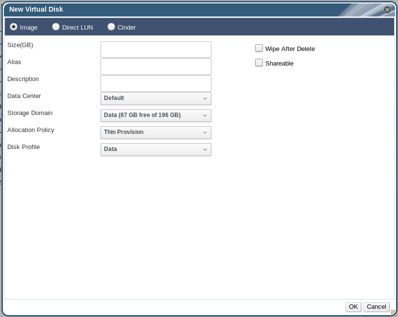
Figure 11.1. Add Virtual Disk Window (Floating Virtual Disk)
- Use the radio buttons to specify whether the virtual disk will be an Image, Direct LUN, or Cinder disk.
- Select the options required for your virtual disk. The options change based on the disk type selected. See Section 11.6.2, “Explanation of Settings in the New Virtual Disk Window” for more details on each option for each disk type.
- Click OK.
Procedure 11.3. Creating a Virtual Disk Attached to a Virtual Machine
- In the Administration Portal, click the Virtual Machines resource tab.
- Select a virtual machine.
- Click the Disks resource tab in the bottom pane.
- Click .
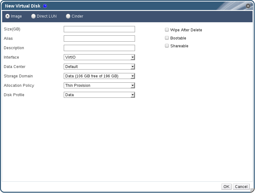
Figure 11.2. Add Virtual Disk Window (Attached Virtual Disk)
- Use the radio buttons to specify whether the virtual disk will be an Image, Direct LUN, or Cinder disk.
- Select the options required for your virtual disk. The options change based on the disk type selected. See Section 11.6.2, “Explanation of Settings in the New Virtual Disk Window” for more details on each option for each disk type.
- Click OK.
11.6.2. Explanation of Settings in the New Virtual Disk Window
Important
- Live storage migration of direct LUN hard disk images is not supported.
- Direct LUN disks are not included in virtual machine exports.
- Direct LUN disks are not included in virtual machine snapshots.
Note
- Size: The size of the new virtual disk in GB.
- Alias: The name of the virtual disk, limited to 40 characters.
- Description: A description of the virtual disk. This field is recommended but not mandatory.
- (Direct LUN): By default the last 4 characters of the LUN ID are inserted into the field. The default behavior can be configured by setting the
PopulateDirectLUNDiskDescriptionWithLUNIdconfiguration key to the appropriate value using theengine-configcommand. The configuration key can be set to-1for the full LUN ID to be used or0for this feature to be ignored. A positive integer populates the description with the corresponding number of characters of the LUN ID. See Section 19.2.2, “Syntax for the engine-config Command” for more information.
- Interface: The virtual interface that the disk presents to virtual machines. The interface type can be updated after stopping all virtual machines that the disk is attached to.
- IDE is a widely used interface for mass storage devices. It does not require additional drivers.
- VirtIO is a simple, high-performance, para-virtualized storage device. It is faster than IDE and requires additional drivers, which have been included since Red Hat Enterprise Linux 5. Windows does not include these drivers, but they can be installed from the guest tools ISO or virtual floppy disk.
- VirtIO maps PCI functions and storage devices 1:1, limiting scalability.
- Because VirtIO is not a true SCSI device, some applications may break when they are moved from physical to virtual machines.
- VirtIO-SCSI is a virtual SCSI HBA for KVM guests. It replaces and supersedes VirtIO. While it provides the same performance as VirtIO, VirtIO-SCSI has significant advantages. VirtIO-SCSI requires additional drivers, which have been included since Red Hat Enterprise Linux 6.4. Windows does not include these drivers, but they can be installed from the guest tools ISO or virtual floppy disk.
Important
VirtIO-SCSI must be enabled in order to appear in the Interface dropdown list. To enable VirtIO-SCSI, select the virtual machine, click Edit, click Show Advanced Options, click the Resource Allocation tab, and click the VirtIO-SCSI Enabled radio button.- VirtIO-SCSI is more scalable than VirtIO, allowing virtual machines to connect to more storage devices.
- VirtIO-SCSI uses standard device naming, so that VirtIO-SCSI disks have the same paths as a bare-metal system. This simplifies physical-to-virtual and virtual-to-virtual migration.
- VirtIO-SCSI can present physical storage devices directly to guests, using SCSI device passthrough.
- Data Center: The data center in which the virtual disk will be available.
- Storage Domain: The storage domain in which the virtual disk will be stored. The drop-down list shows all storage domains available in the given data center, and also shows the total space and currently available space in the storage domain.
- Allocation Policy: The provisioning policy for the new virtual disk.
- Preallocated allocates the entire size of the disk on the storage domain at the time the virtual disk is created. The virtual size and the actual size of a preallocated disk are the same. Preallocated virtual disks take more time to create than thinly provisioned virtual disks, but have better read and write performance. Preallocated virtual disks are recommended for servers and other I/O intensive virtual machines. If a virtual machine is able to write more than 1 GB every four seconds, use preallocated disks where possible.
- Thin Provision allocates 1 GB at the time the virtual disk is created and sets a maximum limit on the size to which the disk can grow, for block-level storage (iSCSI, Fibre Channel). For file-level storage (NFS, Gluster), there is no maximum size; the file can grow. The virtual size of the disk is the maximum limit; the actual size of the disk is the space that has been allocated so far. Thinly provisioned disks are faster to create than preallocated disks and allow for storage over-commitment. Thinly provisioned virtual disks are recommended for desktops.
- Disk Profile: The disk profile assigned to the virtual disk. Disk profiles define the maximum amount of throughput and the maximum level of input and output operations for a virtual disk in a storage domain. Disk profiles are defined on the storage domain level based on storage quality of service entries created for data centers.
- Use Host (Direct LUN): The host on which the LUN will be mounted. You can select any host in the data center.
- Storage Type (Direct LUN): The type of external LUN to add. You can select from either iSCSI or Fibre Channel.
- Discover Targets (Direct LUN): This section can be expanded when you are using iSCSI external LUNs and Targets > LUNs is selected.
- Address - The host name or IP address of the target server.
- Port - The port by which to attempt a connection to the target server. The default port is 3260.
- User Authentication - The iSCSI server requires User Authentication. The User Authentication field is visible when you are using iSCSI external LUNs.
- CHAP username - The user name of a user with permission to log in to LUNs. This field is accessible when the User Authentication check box is selected.
- CHAP password - The password of a user with permission to log in to LUNs. This field is accessible when the User Authentication check box is selected.
- Wipe After Delete: Allows you to enable enhanced security for deletion of sensitive material when the virtual disk is deleted.
- Volume Type: The volume type of the virtual disk. The drop-down list shows all available volume types. The volume type will be managed and configured on OpenStack Cinder.
- Bootable: Allows you to enable the bootable flag on the virtual disk.
- Shareable: Allows you to attach the virtual disk to more than one virtual machine at a time.
- Enable SCSI Pass-Through (Direct LUN): Available when the Interface is set to VirtIO-SCSI. Selecting this check box enables passthrough of a physical SCSI device to the virtual disk. A VirtIO-SCSI interface with SCSI passthrough enabled automatically includes SCSI discard support. When this check box is not selected, the virtual disk uses an emulated SCSI device.
- Allow Privileged SCSI I/O (Direct LUN): Available when the Enable SCSI Pass-Through check box is selected. Selecting this check box enables unfiltered SCSI Generic I/O (SG_IO) access, allowing privileged SG_IO commands on the disk. This is required for persistent reservations.
11.6.3. Overview of Live Storage Migration
- You can live migrate multiple disks at one time.
- Multiple disks for the same virtual machine can reside across more than one storage domain, but the image chain for each disk must reside on a single storage domain.
- You can live migrate disks between any two storage domains in the same data center.
- You cannot live migrate direct LUN hard disk images or disks marked as shareable.
11.6.4. Moving a Virtual Disk
- You can move multiple disks at the same time.
- You can move disks between any two storage domains in the same data center.
- If the virtual disk is attached to a virtual machine that was created based on a template and used the thin provisioning storage allocation option, you must copy the disks for the template on which the virtual machine was based to the same storage domain as the virtual disk.
Procedure 11.4. Moving a Virtual Disk
- Select the Disks tab.
- Select one or more virtual disks to move.
- Click to open the Move Disk(s) window.
- From the Target list, select the storage domain to which the virtual disk(s) will be moved.
- From the Disk Profile list, select a profile for the disk(s), if applicable.
- Click .
Locked and a progress bar indicating the progress of the move operation.
11.6.5. Changing the Disk Interface Type
VirtIO interface can be attached to a virtual machine requiring the VirtIO-SCSI or IDE interface. This provides flexibility to migrate disks for the purpose of backup and restore, or disaster recovery. The disk interface for shareable disks can also be updated per virtual machine. This means that each virtual machine that uses the shared disk can use a different interface type.
Procedure 11.5. Changing a Disk Interface Type
- Select the Virtual Machines tab and stop the appropriate virtual machine(s).
- From the Disks sub-tab, select the disk and click .
- From the Interface list, select the new interface type and click .
Procedure 11.6. Attaching a Disk to a Different Virtual Machine using a Different Interface Type
- Select the Virtual Machines tab and stop the appropriate virtual machine(s).
- Select the virtual machine from which to detach the disk.
- From the Disks sub-tab, select the disk and click .
- From the Virtual Machines tab, select the new virtual machine that the disk will be attached to.
- Click .
- Select the disk in the Attach Virtual Disks window and select the appropriate interface from the Interface drop-down.
- Click .
11.6.6. Copying a Virtual Disk
You can copy a virtual disk from one storage domain to another. The copied disk can be attached to virtual machines.
Procedure 11.7. Copying a Virtual Disk
- Select the Disks tab.
- Select the virtual disks to copy.
- Click the button to open the Copy Disk(s) window.
- Optionally, enter an alias in the Alias text field.
- Use the Target drop-down menus to select the storage domain to which the virtual disk will be copied.
- Click .
The virtual disks are copied to the target storage domain, and have a status of Locked while being copied.
11.6.7. Uploading and Downloading a Virtual Disk to a Storage Domain
IMAGETRANSFERS service to create the transfer, and the IMAGETRANSFER service to specify whether to upload or download the image.
Prerequisites:
- You must configure the Image I/O Proxy (ovirt-imageio-proxy) when running
engine-setup. See Configuring the Red Hat Virtualization Manager in the Installation Guide for more information. - You must import the required certificate authority into the web browser used to access the Administration Portal.
- Internet Explorer 10, Firefox 35, or Chrome 13 or greater is required to perform this upload procedure. Previous browser versions do not support the required HTML5 APIs.
Note
Procedure 11.8. Uploading a Disk Image to a Storage Domain
- Click the Disks resource tab.
- Select Start from the Upload menu.
Note
You can also access this menu by clicking the Storage resource tab, selecting the storage domain, then selecting the Disks sub-tab.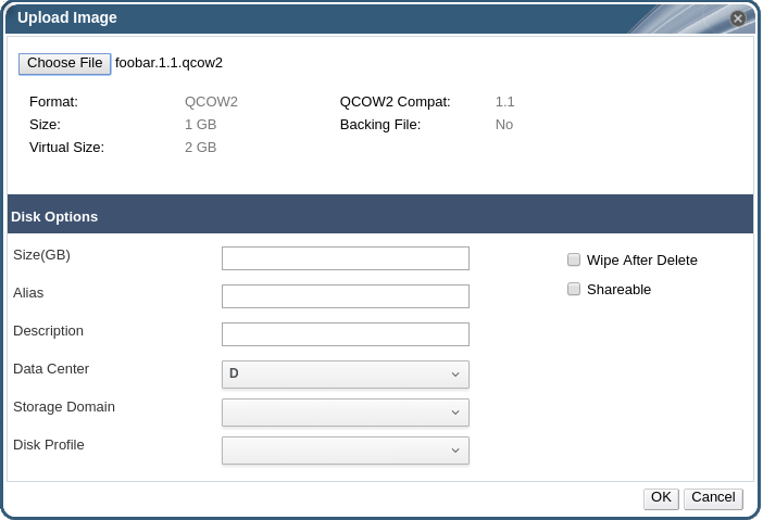
Figure 11.3. The Upload Image Screen
- Click , and select the image on the local disk.
- Fill in the fields in the Disk Options area. See Section 11.6.2, “Explanation of Settings in the New Virtual Disk Window” for a description of the relevant fields.
- Click .
11.6.8. Importing a Disk Image from an Imported Storage Domain
Note
Procedure 11.9. Importing a Disk Image
- Select a storage domain that has been imported into the data center.
- In the details pane, click Disk Import.
- Select one or more disk images and click to open the Import Disk(s) window.
- Select the appropriate Disk Profile for each disk.
- Click to import the selected disks.
11.6.9. Importing an Unregistered Disk Image from an Imported Storage Domain
Note
Procedure 11.10. Importing a Disk Image
- Select a storage domain that has been imported into the data center.
- Right-click the storage domain and select Scan Disks so that the Manager can identify unregistered disks.
- In the details pane, click Disk Import.
- Select one or more disk images and click to open the Import Disk(s) window.
- Select the appropriate Disk Profile for each disk.
- Click to import the selected disks.
11.6.10. Importing a Virtual Disk from an OpenStack Image Service
virtual disks managed by an OpenStack Image Service can be imported into the Red Hat Virtualization Manager if that OpenStack Image Service has been added to the Manager as an external provider.
- Click the Storage resource tab and select the OpenStack Image Service domain from the results list.
- Select the image to import in the Images tab of the details pane.
- Click to open the Import Image(s) window.
- From the Data Center drop-down menu, select the data center into which the virtual disk will be imported.
- From the Domain Name drop-down menu, select the storage domain in which the virtual disk will be stored.
- Optionally, select a quota from the Quota drop-down menu to apply a quota to the virtual disk.
- Click to import the image.
The image is imported as a floating disk and is displayed in the results list of the Disks resource tab. It can now be attached to a virtual machine.
11.6.11. Exporting a Virtual Disk to an OpenStack Image Service
Virtual disks can be exported to an OpenStack Image Service that has been added to the Manager as an external provider.
- Click the Disks resource tab.
- Select the disks to export.
- Click the Export button to open the Export Image(s) window.
- From the Domain Name drop-down list, select the OpenStack Image Service to which the disks will be exported.
- From the Quota drop-down list, select a quota for the disks if a quota is to be applied.
- Click OK.
The virtual disks are exported to the specified OpenStack Image Service where they are managed as virtual disks.
Important
11.6.12. Reclaiming Virtual Disk Space
Limitations
- NFS storage domains must use NFS version 4.2 or higher.
- You cannot sparsify a disk that uses a direct LUN or Cinder.
- You cannot sparsify a disk that uses a preallocated allocation policy. If you are creating a virtual machine from a template, you must select Thin from the Storage Allocation field, or if selecting Clone, ensure that the template is based on a virtual machine that has thin provisioning.
- You can only sparsify active snapshots.
Procedure 11.11. Sparsifying a Disk
- Click the Virtual Machines tab and select the virtual machine. Ensure that its status displays as
Down. If the virtual machine is running you must shut it down before proceeding. - Select the Disks tab in the details pane. Ensure that its status displays as
OK. - Select the Sparsify button. A Sparsify Disks window appears asking you to confirm the sparsify operation for the selected disk.
- Click OK.
Started to sparsify event appears in the Events tab at the bottom of the window during the sparsify operation and the disk's status displays as Locked. When the operation is complete, a Sparsified successfully event appears in the Events tab and the disk's status displays as OK. The unused disk space has been returned to the host and is available for use by other virtual machines.
Note
11.7. Virtual Disks and Permissions
11.7.1. Managing System Permissions for a Virtual Disk
- Create, edit, and remove virtual disks associated with a virtual machine or other resources.
- Edit user permissions for virtual disks.
Note
11.7.2. Virtual Disk User Roles Explained
The table below describes the user roles and privileges applicable to using and administrating virtual disks in the User Portal.
| Role | Privileges | Notes |
|---|---|---|
| DiskOperator | Virtual disk user. | Can use, view and edit virtual disks. Inherits permissions to use the virtual machine to which the virtual disk is attached. |
| DiskCreator | Can create, edit, manage and remove virtual disks within assigned clusters or data centers. | This role is not applied to a specific virtual disk; apply this role to a user for the whole environment with the Configure window. Alternatively apply this role for specific data centers, clusters, or storage domains. |
11.7.3. Assigning an Administrator or User Role to a Resource
Procedure 11.12. Assigning a Role to a Resource
- Use the resource tabs, tree mode, or the search function to find and select the resource in the results list.
- Click the tab in the details pane to list the assigned users, the user's role, and the inherited permissions for the selected resource.
- Click .
- Enter the name or user name of an existing user into the Search text box and click . Select a user from the resulting list of possible matches.
- Select a role from the Role to Assign: drop-down list.
- Click .
11.7.4. Removing an Administrator or User Role from a Resource
Procedure 11.13. Removing a Role from a Resource
- Use the resource tabs, tree mode, or the search function to find and select the resource in the results list.
- Click the tab in the details pane to list the assigned users, the user's role, and the inherited permissions for the selected resource.
- Select the user to remove from the resource.
- Click . The Remove Permission window opens to confirm permissions removal.
- Click .
Chapter 12. External Providers
12.1. Introduction to External Providers in Red Hat Virtualization
- Red Hat Satellite for Host Provisioning
- Satellite is a tool for managing all aspects of the life cycle of both physical and virtual hosts. In Red Hat Virtualization, hosts managed by Satellite can be added to and used by the Red Hat Virtualization Manager as virtualization hosts. After you add a Satellite instance to the Manager, the hosts managed by the Satellite instance can be added by searching for available hosts on that Satellite instance when adding a new host. For more information on installing Red Hat Satellite and managing hosts using Red Hat Satellite, see the Installation Guide and Host Configuration Guide.
- OpenStack Image Service (Glance) for Image Management
- OpenStack Image Service provides a catalog of virtual machine images. In Red Hat Virtualization, these images can be imported into the Red Hat Virtualization Manager and used as floating disks or attached to virtual machines and converted into templates. After you add an OpenStack Image Service to the Manager, it appears as a storage domain that is not attached to any data center. Virtual disks in a Red Hat Virtualization environment can also be exported to an OpenStack Image Service as virtual disks.
- OpenStack Networking (Neutron) for Network Provisioning
- OpenStack Networking provides software-defined networks. In Red Hat Virtualization, networks provided by OpenStack Networking can be imported into the Red Hat Virtualization Manager and used to carry all types of traffic and create complicated network topologies. After you add OpenStack Networking to the Manager, you can access the networks provided by OpenStack Networking by manually importing them.
- OpenStack Volume (Cinder) for Storage Management
- OpenStack Volume provides persistent block storage management for virtual hard drives. The OpenStack Cinder volumes are provisioned by Ceph Storage. In Red Hat Virtualization, you can create disks on OpenStack Volume storage that can be used as floating disks or attached to virtual machines. After you add OpenStack Volume to the Manager, you can create a disk on the storage provided by OpenStack Volume.
- VMware for Virtual Machine Provisioning
- Virtual machines created in VMware can be converted using V2V (virt-v2v) and imported into a Red Hat Virtualization environment. After you add a VMware provider to the Manager, you can import the virtual machines it provides. V2V conversion is performed on a designated proxy host as part of the import operation.
- Xen for Virtual Machine Provisioning
- Virtual machines created in Xen can be converted using V2V (virt-v2v) and imported into a Red Hat Virtualization environment. After you add a Xen host to the Manager, you can import the virtual machines it provides. V2V conversion is performed on a designated proxy host as part of the import operation.
- KVM for Virtual Machine Provisioning
- Virtual machines created in KVM can be imported into a Red Hat Virtualization environment. After you add a KVM host to the Manager, you can import the virtual machines it provides.
- External Network Provider for Network Provisioning
- Supported external sofware-defined network providers include any provider that implements the OpenStack Neutron REST API. Unlike OpenStack Networking (Neutron), the Neutron agent is not used as the virtual interface driver implementation on the host. Instead, the virtual interface driver needs to be provided by the implementer of the external network provider.
12.2. Adding External Providers
12.2.1. Adding a Red Hat Satellite Instance for Host Provisioning
Procedure 12.1. Adding a Satellite Instance for Host Provisioning
- Select the External Providers entry in the tree pane.
- Click to open the Add Provider window.
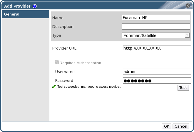
Figure 12.1. The Add Provider Window
- Enter a Name and Description.
- From the Type list, ensure that Foreman/Satellite is selected.
- Enter the URL or fully qualified domain name of the machine on which the Satellite instance is installed in the Provider URL text field. You do not need to specify a port number.
Important
IP addresses cannot be used to add a Satellite instance. - Enter the Username and Password for the Satellite instance. You must use the same user name and password as you would use to log in to the Satellite provisioning portal.
- Test the credentials:
- Click Test to test whether you can authenticate successfully with the Satellite instance using the provided credentials.
- If the Satellite instance uses SSL, the Import provider certificates window opens; click OK to import the certificate that the Satellite instance provides.
Important
You must import the certificate that the Satellite instance provides to ensure the Manager can communicate with the instance.
- Click .
12.2.2. Adding an OpenStack Image (Glance) Instance for Image Management
Procedure 12.2. Adding an OpenStack Image (Glance) Instance for Image Management
- Select the External Providers entry in the tree pane.
- Click to open the Add Provider window.
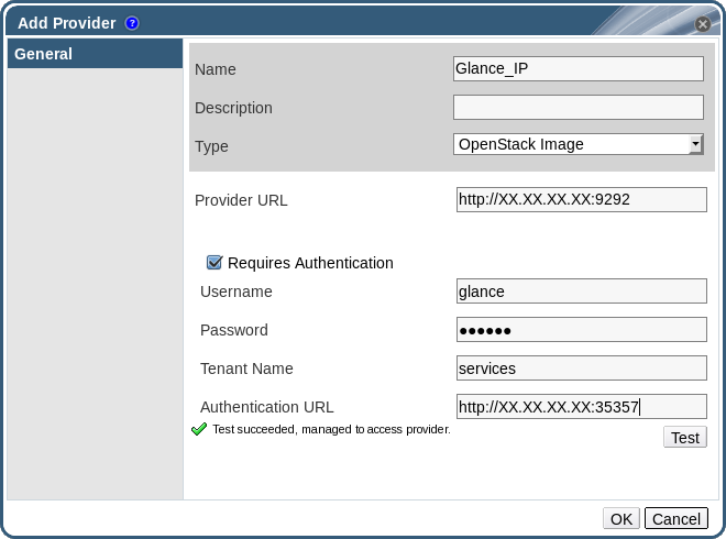
Figure 12.2. The Add Provider Window
- Enter a Name and Description.
- From the Type list, select OpenStack Image.
- Enter the URL or fully qualified domain name of the machine on which the OpenStack Image instance is installed in the Provider URL text field.
- Optionally, select the Requires Authentication check box and enter the Username, Password, Tenant Name, and Authentication URL for the OpenStack Image instance. You must use the user name and password for the OpenStack Image user registered in Keystone, the tenant of which the OpenStack Image instance is a member, and the URL and port of the Keystone server.
- Test the credentials:
- Click Test to test whether you can authenticate successfully with the OpenStack Image instance using the provided credentials.
- If the OpenStack Image instance uses SSL, the Import provider certificates window opens; click OK to import the certificate that the OpenStack Image instance provides.
Important
You must import the certificate that the OpenStack Image instance provides to ensure the Manager can communicate with the instance.
- Click .
12.2.3. Adding an OpenStack Networking (Neutron) Instance for Network Provisioning
Important
Procedure 12.3. Adding an OpenStack Networking (Neutron) Instance for Network Provisioning
- Select the External Providers entry in the tree pane.
- Click to open the Add Provider window.

Figure 12.3. The Add Provider Window
- Enter a Name and Description.
- From the Type list, select OpenStack Networking.
- Ensure that Open vSwitch is selected in the Networking Plugin field.
- Enter the URL or fully qualified domain name of the machine on which the OpenStack Networking instance is installed in the Provider URL text field, followed by the port number. The Read Only check box is selected by default. This prevents users from modifying the OpenStack Networking instance.
Important
You must leave the Read Only check box selected for your setup to be supported by Red Hat. - Optionally, select the Requires Authentication check box and enter the Username, Password, Tenant Name, and Authentication URL for the OpenStack Networking instance. You must use the user name and password for the OpenStack Networking user registered in Keystone, the tenant of which the OpenStack Networking instance is a member, and the URL and port of the Keystone server.
- Test the credentials:
- Click Test to test whether you can authenticate successfully with the OpenStack Networking instance using the provided credentials.
- If the OpenStack Networking instance uses SSL, the Import provider certificates window opens; click OK to import the certificate that the OpenStack Networking instance provides to ensure the Manager can communicate with the instance.
Warning
The following steps are provided only as a Technology Preview. Red Hat Virtualization only supports preconfigured neutron hosts. - Click the Agent Configuration tab.
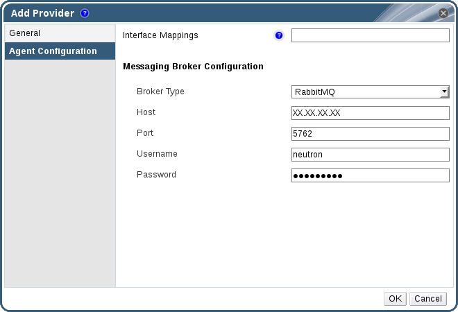
Figure 12.4. The Agent Configuration Tab
- Enter a comma-separated list of interface mappings for the Open vSwitch agent in the Interface Mappings field.
- Select the message broker type that the OpenStack Networking instance uses from the Broker Type list.
- Enter the URL or fully qualified domain name of the host on which the message broker is hosted in the Host field.
- Enter the Port by which to connect to the message broker. This port number will be 5762 by default if the message broker is not configured to use SSL, and 5761 if it is configured to use SSL.
- Enter the Username and Password of the OpenStack Networking user registered in the message broker instance.
- Click .
12.2.4. Adding an OpenStack Volume (Cinder) Instance for Storage Management
Important
Procedure 12.4. Adding an OpenStack Volume (Cinder) Instance for Storage Management
- Select the External Providers entry in the tree pane.
- Click to open the Add Provider window.
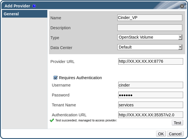
Figure 12.5. The Add Provider Window
- Enter a Name and Description.
- From the Type list, select OpenStack Volume.
- Select the Data Center to which OpenStack Volume storage volumes will be attached.
- Enter the URL or fully qualified domain name of the machine on which the OpenStack Volume instance is installed, followed by the port number, in the Provider URL text field.
- Optionally, select the Requires Authentication check box and enter the Username, Password, Tenant Name, and Authentication URL for the OpenStack Volume instance. You must use the user name and password for the OpenStack Volume user registered in Keystone, the tenant of which the OpenStack Volume instance is a member, and the URL, port, and API version of the Keystone server.
- Click Test to test whether you can authenticate successfully with the OpenStack Volume instance using the provided credentials.
- Click .
- If client Ceph authentication (cephx) is enabled, you must also complete the following steps. The cephx protocol is enabled by default.
- On your Ceph server, create a new secret key for the
client.cinderuser using theceph auth get-or-createcommand. See Cephx Config Reference for more information on cephx, and Managing Users for more information on creating keys for new users. If a key already exists for theclient.cinderuser, retrieve it using the same command. - In the Administration Portal, select the newly-created Cinder external provider from the Providers list.
- Click the Authentication Keys sub-tab.
- Click .
- Enter the secret key in the Value field.
- Copy the automatically-generated UUID, or enter an existing UUID in the text field.
- On your Cinder server, add the UUID from the previous step and the
cinderuser to/etc/cinder/cinder.conf:rbd_secret_uuid = UUID rbd_user = cinder
12.2.5. Adding a VMware Instance as a Virtual Machine Provider
Note
Procedure 12.5. Adding a VMware vCenter Instance as a Virtual Machine Provider
- Select the External Providers entry in the tree pane.
- Click to open the Add Provider window.
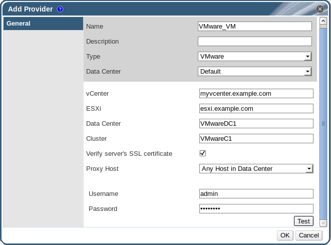
Figure 12.6. The Add Provider Window
- Enter a Name and Description.
- From the Type list, select VMware.
- Select the Data Center into which VMware virtual machines will be imported, or select Any Data Center to instead specify the destination data center during individual import operations (using the function in the Virtual Machines tab).
- Enter the IP address or fully qualified domain name of the VMware vCenter instance in the vCenter field.
- Enter the IP address or fully qualified domain name of the host from which the virtual machines will be imported in the ESXi field.
- Enter the name of the data center in which the specified ESXi host resides in the Data Center field.
- If you have exchanged the SSL certificate between the ESXi host and the Manager, leave Verify server's SSL certificate checked to verify the ESXi host's certificate. If not, uncheck the option.
- Select a host in the chosen data center with virt-v2v installed to serve as the Proxy Host during virtual machine import operations. This host must also be able to connect to the network of the VMware vCenter external provider. If you selected Any Data Center above, you cannot choose the host here, but instead can specify a host during individual import operations (using the function in the Virtual Machines tab).
- Enter the Username and Password for the VMware vCenter instance. The user must have access to the VMware data center and ESXi host on which the virtual machines reside.
- Test the credentials:
- Click Test to test whether you can authenticate successfully with the VMware vCenter instance using the provided credentials.
- If the VMware vCenter instance uses SSL, the Import provider certificates window opens; click OK to import the certificate that the VMware vCenter instance provides.
Important
You must import the certificate that the VMware vCenter instance provides to ensure the Manager can communicate with the instance.
- Click .
12.2.6. Adding a Xen Host as a Virtual Machine Provider
Note
Procedure 12.6. Adding a Xen Instance as a Virtual Machine Provider
- Enable public key authentication between the proxy host and the Xen host:
- Log in to the proxy host and generate SSH keys for the
vdsmuser.# sudo -u vdsm ssh-keygen
- Copy the
vdsmuser's public key to the Xen host. The proxy host'sknown_hostsfile will also be updated to include the host key of the Xen host.# sudo -u vdsm ssh-copy-id root@xenhost.example.com
- Log in to the Xen host to verify that the login works correctly.
# sudo -u vdsm ssh root@xenhost.example.com
- Select the External Providers entry in the tree pane.
- Click to open the Add Provider window.
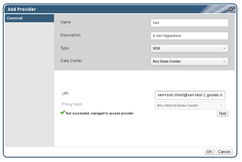
Figure 12.7. The Add Provider Window
- Enter a Name and Description.
- From the Type list, select XEN.
- Select the Data Center into which Xen virtual machines will be imported, or select Any Data Center to specify the destination data center during individual import operations (using the function in the Virtual Machines tab).
- Enter the URI in the field.
- Select a host in the chosen data center with virt-v2v installed to serve as the Proxy Host during virtual machine import operations. This host must also be able to connect to the network of the Xen external provider. If you selected Any Data Center above, you cannot choose the host here, but instead can specify a host during individual import operations (using the function in the Virtual Machines tab).
- Click Test to test whether you can authenticate successfully with the Xen host.
- Click .
12.2.7. Adding a KVM Host as a Virtual Machine Provider
Procedure 12.7. Adding a KVM Host as a Virtual Machine Provider
- Enable public key authentication between the proxy host and the KVM host:
- Log in to the proxy host and generate SSH keys for the
vdsmuser.# sudo -u vdsm ssh-keygen
- Copy the
vdsmuser's public key to the KVM host. The proxy host'sknown_hostsfile will also be updated to include the host key of the KVM host.# sudo -u vdsm ssh-copy-id root@kvmhost.example.com
- Log in to the KVM host to verify that the login works correctly.
# sudo -u vdsm ssh root@kvmhost.example.com
- Select the External Providers entry in the tree pane.
- Click to open the Add Provider window.
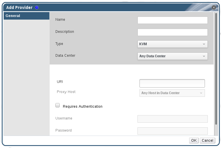
Figure 12.8. The Add Provider Window
- Enter a Name and Description.
- From the Type list, select KVM.
- Select the Data Center into which KVM virtual machines will be imported, or select Any Data Center to specify the destination data center during individual import operations (using the function in the Virtual Machines tab).
- Enter the URI in the field.
- Select a host in the chosen data center to serve as the Proxy Host during virtual machine import operations. This host must also be able to connect to the network of the KVM external provider. If you selected Any Data Center in the Data Center field above, you cannot choose the host here. The field is greyed out and shows Any Host in Data Center. Instead you can specify a host during individual import operations (using the function in the Virtual Machines tab).
- Optionally, select the Requires Authentication check box and enter the Username and Password for the KVM host. The user must have access to the KVM host on which the virtual machines reside.
- Click Test to test whether you can authenticate successfully with the KVM host using the provided credentials.
- Click .
12.2.8. Adding an External Network Provider
Procedure 12.8. Adding an External Network Provider for Network Provisioning
- Select the External Providers entry in the tree pane.
- Click .
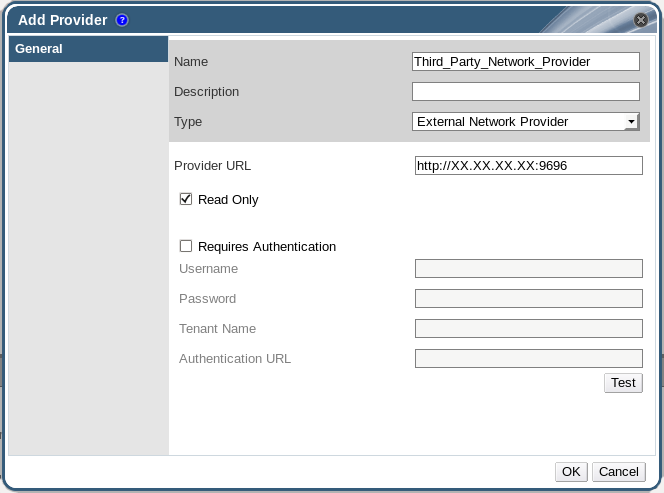
Figure 12.9. The Add Provider Window
- Enter a Name and Description.
- From the Type list, select External Network Provider.
- Enter the URL or fully qualified domain name of the machine on which the external network provider is installed in the Provider URL text field, followed by the port number. The Read-Only check box is selected by default. This prevents users from modifying the external network provider.
Important
You must leave the Read-Only check box selected for your setup to be supported by Red Hat. - Optionally, select the Requires Authentication check box and enter the Username, Password, Tenant Name, and Authentication URL for the external network provider.
- Test the credentials:
- Click Test to test whether you can authenticate successfully with the external network provider using the provided credentials.
- If the external network provider uses SSL, the Import provider certificates window opens; click OK to import the certificate that the external network provider provides to ensure the Manager can communicate with the instance.
- Click .
12.2.9. Adding Open Virtual Network (OVN) as an External Network Provider
Important
- Install the OVN virtual interface driver on any hosts to which you want to add OVN networks. The virtual interface driver connects vNICs to the appropriate OVS bridge and OVN logical network.
- Install the OVN provider, a proxy used by the Manager to interact with OVN. The OVN provider can be installed on any machine, but must be able to communicate with the OVN central server and the Manager.
- Add the OVN provider to Red Hat Virtualization as an external network provider.
Prerequisites
- The following packages are required by the OVN virtual interface driver and must be available on the hosts:
- openvswitch-ovn-host
- openvswitch
- openvswitch-ovn-common
- python-openvswitch
- The following packages are required by the OVN provider and must be available on the provider machine:
- openvswitch-ovn-central
- openvswitch
- openvswitch-ovn-common
- python-openvswitch
Procedure 12.9. Adding Open Virtual Network (OVN) as an External Network Provider
- Install and configure the OVN virtual interface driver on any hosts to which you want to add OVN networks.
- Install the driver:
- On a RHEL host:
# yum install ovirt-provider-ovn-driver
- On Red Hat Virtualization Host (RHVH), the RPM must be manually built and installed:
# git clone https://gerrit.ovirt.org/ovirt-provider-ovn
# cd ovirt-provider-ovn
# make rpm
# cd
# yum install rpmbuild/RPMS/noarch/ovirt-provider-ovn-driver-version.noarch.rpm
- Start and enable the service:
# systemctl start ovn-controller
# systemctl enable ovn-controller
- Configure the service:
# vdsm-tool ovn-config OVN_central_server_IP local_OVN_tunneling_IP
The local IP address used for OVN tunneling must be reachable by the OVN central server and by other hosts using OVN. It can be theovirtmgmtinterface on the host. - Open port 6081 in the firewall. This can be done either manually or by adding
ovn-host-firewall-serviceto the appropriate zone:# firewall-cmd --zone=ZoneName --add-service=ovn-host-firewall-service --permanent # firewall-cmd --reload
- Install and configure the OVN provider.
- Install the provider:
- If you are installing the provider on the same machine as the Manager:
# yum install ovirt-provider-ovn
- If you are not installing the provider on the same machine as the Manager, the RPM must be manually built and installed:
# git clone https://gerrit.ovirt.org/ovirt-provider-ovn
# cd ovirt-provider-ovn
# make rpm
# cd
# yum install rpmbuild/RPMS/noarch/ovirt-provider-ovn-version.noarch.rpm
- If you are not installing the provider on the same machine as the OVN central server, add the following entry to the
/etc/ovirt-provider-ovn/ovirt-provider-ovn.conffile:ovn-remote=tcp:OVN_central_server_IP:6641
- Open ports 9696, 6641, and 6642 in the firewall to allow communication between the OVN provider, the OVN central server, and the Manager. This can be done either manually or by adding the
ovirt-provider-ovnandovirt-provider-ovn-centralservices to the appropriate zone:# firewall-cmd --zone=ZoneName --add-service=ovirt-provider-ovn --permanent # firewall-cmd --zone=ZoneName --add-service=ovirt-provider-ovn-central --permanent # firewall-cmd --reload
- Start and enable the service:
# systemctl start ovirt-provider-ovn
# systemctl enable ovirt-provider-ovn
- Configure the OVN central server to listen to requests from ports 6642 and 6641:
# ovn-sbctl set-connection ptcp:6642
# ovn-nbctl set-connection ptcp:6641
- In the Administration Portal, select the External Providers entry in the tree pane.
- Click .
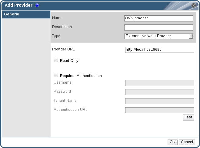
Figure 12.10. The Add Provider Window
- Enter a Name and Description.
- From the Type list, select External Network Provider.
- Enter the URL or fully qualified domain name of the OVN provider in the Provider URL text field, followed by the port number. If the OVN provider and the OVN central server are on separate machines, this is the URL of the provider machine, not the central server. If the OVN provider is on the same machine as the Manager, the URL can remain the default
http://localhost:9696. - Clear the Read-Only check box to allow creating new OVN networks from the Red Hat Virtualization Manager.
- Clear the Requires Authentication check box. Authentication and SSL are currently not supported for OVN external network providers.
- Click .
12.2.10. Add Provider General Settings Explained
|
Setting
|
Explanation
|
|---|---|
|
Name
|
A name to represent the provider in the Manager.
|
|
Description
|
A plain text, human-readable description of the provider.
|
|
Type
|
The type of external provider. Changing this setting alters the available fields for configuring the provider.
Foreman/Satellite
OpenStack Image
OpenStack Networking
OpenStack Volume
VMware
Xen
KVM
External Network Provider
|
|
Test
|
Allows users to test the specified credentials. This button is available to all provider types.
|
12.2.11. Add Provider Agent Configuration Settings Explained
|
Setting
|
Explanation
|
|---|---|
|
Interface Mappings
|
A comma-separated list of mappings in the format of label:interface.
|
|
Broker Type
|
The message broker type that the OpenStack Networking instance uses. Select RabbitMQ or Qpid.
|
|
Host
|
The URL or fully qualified domain name of the machine on which the message broker is installed.
|
|
Port
|
The remote port by which a connection with the above host is to be made. By default, this port is 5762 if SSL is not enabled on the host, and 5761 if SSL is enabled.
|
|
Username
|
A user name for authenticating the OpenStack Networking instance with the above message broker. By default, this user name is
neutron.
|
|
Password
|
The password against which the above user name is to be authenticated.
|
12.3. Editing External Providers
12.3.1. Editing an External Provider
Procedure 12.10. Editing an External Provider
- Select the External Providers entry in the tree pane.
- Select the external provider to edit.
- Click the button to open the Edit Provider window.
- Change the current values for the provider to the preferred values.
- Click .
12.4. Removing External Providers
12.4.1. Removing an External Provider
Procedure 12.11. Removing an External Provider
- Select the External Providers entry in the tree pane.
- Select the external provider to remove.
- Click .
- Click in the Remove Provider(s) window to confirm the removal of this provider.
Part III. Administering the Environment
Chapter 13. Backups and Migration
13.1. Backing Up and Restoring the Red Hat Virtualization Manager
13.1.1. Backing up Red Hat Virtualization Manager - Overview
engine-backup tool to take regular backups of the Red Hat Virtualization Manager. The tool backs up the engine database and configuration files into a single file and can be run without interrupting the ovirt-engine service.
Warning
engine-backup tool must be used for backup and restoration. If a third-party tool is used, it must back up the tar file produced by the engine-backup tool.
13.1.2. Syntax for the engine-backup Command
engine-backup command works in one of two basic modes:
# engine-backup --mode=backup
# engine-backup --mode=restore
engine-backup --help for a full list of parameters and their function.
Basic Options
--mode- Specifies whether the command will perform a backup operation or a restore operation. Two options are available -
backup, andrestore. This is a required parameter. --file- Specifies the path and name of a file into which backups are to be taken in backup mode, and the path and name of a file from which to read backup data in restore mode. This is a required parameter in both backup mode and restore mode.
--log- Specifies the path and name of a file into which logs of the backup or restore operation are to be written. This parameter is required in both backup mode and restore mode.
--scope- Specifies the scope of the backup or restore operation. There are four options:
all, which backs up or restores all databases and configuration data;files, which backs up or restores only files on the system;db, which backs up or restores only the Manager database; anddwhdb, which backs up or restores only the Data Warehouse database. The default scope isall.The--scopeparameter can be specified multiple times in the sameengine-backupcommand.
Manager Database Options
engine-backup command in restore mode. The option syntax below applies to restoring the Manager database. The same options exist for restoring the Data Warehouse database. See engine-backup --help for the Data Warehouse option syntax.
--provision-db- Creates a PostgreSQL database for the Manager database backup to be restored to. This is a required parameter when restoring a backup on a remote host or fresh installation that does not have a PostgreSQL database already configured.
--change-db-credentials- Allows you to specify alternate credentials for restoring the Manager database using credentials other than those stored in the backup itself. See
engine-backup --helpfor the additional parameters required by this parameter. --restore-permissionsor--no-restore-permissions- Restores (or does not restore) the permissions of database users. One of these parameters is required when restoring a backup.
Note
If a backup contains grants for extra database users, restoring the backup with the--restore-permissionsand--provision-db(or--provision-dwh-db) options will create the extra users with random passwords. You must change these passwords manually if the extra users require access to the restored system. See https://access.redhat.com/articles/2686731.
13.1.3. Creating a Backup with the engine-backup Command
engine-backup command while the Manager is active. Append one of the following options to --scope to specify which backup to perform:
all: A full backup of all databases and configuration files on the Managerfiles: A backup of only the files on the systemdb: A backup of only the Manager databasedwhdb: A backup of only the Data Warehouse database
Important
all, must be accompanied by the files scope, or a filesystem backup.
Procedure 13.1. Example Usage of the engine-backup Command
- Log on to the machine running the Red Hat Virtualization Manager.
- Create a backup:
Example 13.1. Creating a Full Backup
# engine-backup --scope=all --mode=backup --file=file_name --log=log_file_name
Example 13.2. Creating a Manager Database Backup
# engine-backup --scope=files --scope=db --mode=backup --file=file_name --log=log_file_name
Replace thedboption withdwhdbto back up the Data Warehouse database.Atarfile containing a backup is created using the path and file name provided.
tar files containing the backups can now be used to restore the environment.
13.1.4. Restoring a Backup with the engine-backup Command
engine-backup command involves more steps than creating a backup does, depending on the restoration destination. For example, the engine-backup command can be used to restore backups to fresh installations of Red Hat Virtualization, on top of existing installations of Red Hat Virtualization, and using local or remote databases.
Important
version file located in the root directory of the unpacked files.
13.1.5. Restoring a Backup to a Fresh Installation
engine-backup command can be used to restore a backup to a fresh installation of the Red Hat Virtualization Manager. The following procedure must be performed on a machine on which the base operating system has been installed and the required packages for the Red Hat Virtualization Manager have been installed, but the engine-setup command has not yet been run. This procedure assumes that the backup file or files can be accessed from the machine on which the backup is to be restored.
Warning
tar backup file produced by the engine-backup tool. If a third-party tool is used, it must create a backup of the tar file.
Procedure 13.2. Restoring a Backup to a Fresh Installation
- Log on to the Manager machine. If you are restoring the engine database to a remote host, you will need to log on to and perform the relevant actions on that host. Likewise, if also restoring the Data Warehouse to a remote host, you will need to log on to and perform the relevant actions on that host.
- Restore a complete backup or a database-only backup.
- Restore a complete backup:
# engine-backup --mode=restore --file=file_name --log=log_file_name --provision-db --restore-permissions
If Data Warehouse is also being restored as part of the complete backup, provision the additional database:engine-backup --mode=restore --file=file_name --log=log_file_name --provision-db --provision-dwh-db --restore-permissions
- Restore a database-only backup by restoring the configuration files and database backup:
# engine-backup --mode=restore --scope=files --scope=db --file=file_name --log=log_file_name --provision-db --restore-permissions
The example above restores a backup of the Manager database.# engine-backup --mode=restore --scope=files --scope=dwhdb --file=file_name --log=log_file_name --provision-dwh-db --restore-permissions
The example above restores a backup of the Data Warehouse database.
If successful, the following output displays:You should now run engine-setup. Done.
- Run the following command and follow the prompts to configure the restored Manager:
# engine-setup
13.1.6. Restoring a Backup to Overwrite an Existing Installation
engine-backup command can restore a backup to a machine on which the Red Hat Virtualization Manager has already been installed and set up. This is useful when you have taken a backup up of an installation, performed changes on that installation, and then want to restore the installation from the backup.
Warning
tar backup file produced by the engine-backup tool. If a third-party tool is used, it must create a backup of the tar file.
Important
engine-cleanup command to clean up the existing installation before using the engine-backup command. Because the engine-cleanup command only cleans the engine database, and does not drop the database or delete the user that owns that database, you do not need to create a new database or specify the database credentials because the user and database already exist.
Procedure 13.3. Restoring a Backup to Overwrite an Existing Installation
- Log on to the Red Hat Virtualization Manager machine.
- Remove the configuration files and clean the database associated with the Manager:
# engine-cleanup
- Restore a full backup or a database-only backup:
- Restore a full backup:
# engine-backup --mode=restore --file=file_name --log=log_file_name --restore-permissions
- Restore a database-only backup by restoring the configuration files and the database backup:
# engine-backup --mode=restore --scope=files --scope=db --file=file_name --log=log_file_name --restore-permissions
The example above restores a backup of the Manager database. If necessary, also restore the Data Warehouse database:# engine-backup --mode=restore --scope=dwhdb --file=file_name --log=log_file_name --restore-permissions
If successful, the following output displays:You should now run engine-setup. Done.
- Run the following command and follow the prompts to reconfigure the firewall and ensure the
ovirt-engineservice is correctly configured:# engine-setup
13.1.7. Restoring a Backup with Different Credentials
engine-backup command can restore a backup to a machine on which the Red Hat Virtualization Manager has already been installed and set up, but the credentials of the database in the backup are different to those of the database on the machine on which the backup is to be restored. This is useful when you have taken a backup of an installation and want to restore the installation from the backup to a different system.
Important
engine-cleanup command to clean up the existing installation before using the engine-backup command. Because the engine-cleanup command only cleans the engine database, and does not drop the database or delete the user that owns that database, you do not need to create a new database or specify the database credentials because the user and database already exist. However, if the credentials for the owner of the engine database are not known, you must change them before you can restore the backup.
Procedure 13.4. Restoring a Backup with Different Credentials
- Log on to the machine on which the Red Hat Virtualization Manager is installed.
- Run the following command and follow the prompts to remove the configuration files for and clean the database associated with the Manager:
# engine-cleanup
- Change the password for the owner of the engine database if the credentials of that user are not known:
- Enter the postgresql command line:
# su postgres
$ psql
- Change the password of the user that owns the
enginedatabase:postgres=# alter role user_name encrypted password 'new_password';
Repeat this for the user that owns theovirt_engine_dwhdatabase if necessary.
- Restore a complete backup or a database-only backup with the
--change-db-credentialsparameter to pass the credentials of the new database. The database_location for a database local to the Manager islocalhost.Note
The following examples use a--*passwordoption for each database without specifying a password, which will prompt for a password for each database. Passwords can be supplied for these options in the command itself, however this is not recommended as the password will then be stored in the shell history. Alternatively,--*passfile=password_file options can be used for each database to securely pass the passwords to theengine-backuptool without the need for interactive prompts.- Restore a complete backup:
# engine-backup --mode=restore --file=file_name --log=log_file_name --change-db-credentials --db-host=database_location --db-name=database_name --db-user=engine --db-password --no-restore-permissions
If Data Warehouse is also being restored as part of the complete backup, include the revised credentials for the additional database:engine-backup --mode=restore --file=file_name --log=log_file_name --change-db-credentials --db-host=database_location --db-name=database_name --db-user=engine --db-password --change-dwh-db-credentials --dwh-db-host=database_location --dwh-db-name=database_name --dwh-db-user=ovirt_engine_history --dwh-db-password --no-restore-permissions
- Restore a database-only backup by restoring the configuration files and the database backup:
# engine-backup --mode=restore --scope=files --scope=db --file=file_name --log=log_file_name --change-db-credentials --db-host=database_location --db-name=database_name --db-user=engine --db-password --no-restore-permissions
The example above restores a backup of the Manager database.# engine-backup --mode=restore --scope=files --scope=dwhdb --file=file_name --log=log_file_name --change-dwh-db-credentials --dwh-db-host=database_location --dwh-db-name=database_name --dwh-db-user=ovirt_engine_history --dwh-db-password --no-restore-permissions
The example above restores a backup of the Data Warehouse database.
If successful, the following output displays:You should now run engine-setup. Done.
- Run the following command and follow the prompts to reconfigure the firewall and ensure the
ovirt-engineservice is correctly configured:# engine-setup
13.1.8. Migrating the Engine Database to a Remote Server Database
engine database to a remote database server after the Red Hat Virtualization Manager has been initially configured. Use engine-backup to create a database backup and restore it on the new database server. This procedure assumes that the new database server has Red Hat Enterprise Linux 7 installed and the appropriate subscriptions configured. See Subscribing to the Required Entitlements in the Installation Guide.
Procedure 13.5. Migrating the Database
- Log in to the Red Hat Virtualization Manager machine and stop the
ovirt-engineservice so that it does not interfere with the engine backup:# systemctl stop ovirt-engine.service
- Create the
enginedatabase backup:# engine-backup --scope=files --scope=db --mode=backup --file=file_name --log=log_file_name
- Copy the backup file to the new database server:
# scp /tmp/engine.dump root@new.database.server.com:/tmp
- Log in to the new database server and install
engine-backup:# yum install ovirt-engine-tools-backup
- Restore the database on the new database server. file_name is the backup file copied from the Manager.
# engine-backup --mode=restore --scope=files --scope=db --file=file_name --log=log_file_name --provision-db --no-restore-permissions
- Now that the database has been migrated, start the
ovirt-engineservice:# systemctl start ovirt-engine.service
13.2. Backing Up and Restoring Virtual Machines Using the Backup and Restore API
13.2.1. The Backup and Restore API
Note
13.2.2. Backing Up a Virtual Machine
Procedure 13.6. Backing Up a Virtual Machine
- Using the REST API, create a snapshot of the virtual machine to back up:
POST /api/vms/11111111-1111-1111-1111-111111111111/snapshots/ HTTP/1.1
Accept: application/xml
Content-type: application/xml

<snapshot>
    <description>BACKUP</description>
</snapshot>
Note
When you take a snapshot of a virtual machine, a copy of the configuration data of the virtual machine as at the time the snapshot was taken is stored in thedataattribute of theconfigurationattribute ininitializationunder the snapshot.Important
You cannot take snapshots of disks that are marked as shareable or that are based on direct LUN disks. - Retrieve the configuration data of the virtual machine from the
dataattribute under the snapshot:GET /api/vms/11111111-1111-1111-1111-111111111111/snapshots/11111111-1111-1111-1111-111111111111 HTTP/1.1 Accept: application/xml Content-type: application/xml
- Identify the disk ID and snapshot ID of the snapshot:
GET /api/vms/11111111-1111-1111-1111-111111111111/snapshots/11111111-1111-1111-1111-111111111111/disks HTTP/1.1
Accept: application/xml
Content-type: application/xml
- Attach the snapshot to the backup virtual machine as an active disk attachment, with the correct interface type (for example,
virtio_scsi):POST /api/vms/22222222-2222-2222-2222-222222222222/diskattachments/ HTTP/1.1 Accept: application/xml Content-type: application/xml <disk_attachment> <active>true</active> <interface>virtio_scsi</interface> <disk id="11111111-1111-1111-1111-111111111111"> <snapshot id="11111111-1111-1111-1111-111111111111"/> </disk> </disk_attachment>
- Use the backup software on the backup virtual machine to back up the data on the snapshot disk.
- Remove the snapshot disk attachment from the backup virtual machine:
DELETE /api/vms/22222222-2222-2222-2222-222222222222/diskattachments/11111111-1111-1111-1111-111111111111  HTTP/1.1
Accept: application/xml
Content-type: application/xml
- Optionally, delete the snapshot:
DELETE /api/vms/11111111-1111-1111-1111-111111111111/snapshots/11111111-1111-1111-1111-111111111111 HTTP/1.1
Accept: application/xml
Content-type: application/xml
13.2.3. Restoring a Virtual Machine
Procedure 13.7. Restoring a Virtual Machine
- In the Administration Portal, create a floating disk on which to restore the backup. See Section 11.6.1, “Creating a Virtual Disk” for details on how to create a floating disk.
- Attach the disk to the backup virtual machine:
POST /api/vms/22222222-2222-2222-2222-222222222222/disks/ HTTP/1.1
Accept: application/xml
Content-type: application/xml

<disk id="11111111-1111-1111-1111-111111111111">
</disk>
- Use the backup software to restore the backup to the disk.
- Detach the disk from the backup virtual machine:
DELETE /api/vms/22222222-2222-2222-2222-222222222222/disks/11111111-1111-1111-1111-111111111111 HTTP/1.1 Accept: application/xml Content-type: application/xml <action> <detach>true</detach> </action> - Create a new virtual machine using the configuration data of the virtual machine being restored:
POST /api/vms/ HTTP/1.1 Accept: application/xml Content-type: application/xml <vm> <cluster> <name>cluster_name</name> </cluster> <name>NAME</name> ... </vm> - Attach the disk to the new virtual machine:
POST /api/vms/33333333-3333-3333-3333-333333333333/disks/ HTTP/1.1
Accept: application/xml
Content-type: application/xml

<disk id="11111111-1111-1111-1111-111111111111">
</disk>
Chapter 14. Errata Management with Red Hat Satellite
Important
Procedure 14.1. Configuring Red Hat Virtualization Errata
- Associate the Manager by adding the required Satellite server as an external provider. See Section 12.2.1, “Adding a Red Hat Satellite Instance for Host Provisioning” for more information.
Note
The Manager must be registered to the Satellite server as a content host and have the katello-agent package installed.For more information on how to configure a host registration see Configuring a Host for Registration in the Red Hat Satellite User Guide and for more information on how to register a host and install the katello-agent package see Registration in the Red Hat Satellite User Guide - Optionally, configure the required hosts to display available errata. See Section 7.5.3, “Configuring Satellite Errata Management for a Host” for more information.
- Optionally, configure the required virtual machines to display available errata. The associated host needs to be configured prior to configuring the required virtual machines. See Configuring Red Hat Satellite Errata Management for a Virtual Machine in the Virtual Machine Management Guide for more information.
Procedure 14.2. Viewing Red Hat Virtualization Manager Errata
- Select the Errata entry in the tree pane.
- Click the Security, Bugs, or Enhancements checkboxes to view only those errata types.
Chapter 15. Automating Configuration Tasks using Ansible
Note
# yum install ansible
15.1. Ansible Roles
15.1.1. Installing Ansible Roles
rhel-7-server-rhv-4.1-rpms repository. See Subscribing to the Required Entitlements in the Installation Guide for more information.
# yum install ovirt-ansible-roles
/usr/share/ansible/roles. The structure of the ovirt-ansible-roles package is as follows:
/usr/share/ansible/roles- stores the roles./usr/share/doc/ovirt-ansible-roles/- stores the examples, a basic overview, and the licence./usr/share/doc/ansible/roles/role_name- stores the documentation specific to the role.
15.1.2. Using Ansible Roles to Configure Red Hat Virtualization
Prerequisites
- Ensure the
roles_pathoption in/etc/ansible/ansible.cfgpoints to the location of your Ansible roles (/usr/share/ansible/roles). - Ensure that you have the Python SDK installed on the machine running the playbook.
Procedure 15.1. Configuring Red Hat Virtualization using Ansible Roles
- Create a file in your working directory to store the Red Hat Virtualization Manager user password:
# cat passwords.yml
  ---
  engine_password: youruserpassword
- Encrypt the user password. You will be asked for a vault password.
# ansible-vault encrypt passwords.yml
New Vault password:
Confirm New Vault password:
- Create a file that stores the Manager details such as the url, certificate location, and user.
# cat engine_vars.yml
---
engine_url: https://example.engine.redhat.com/ovirt-engine/api
engine_user: admin@internal
engine_cafile: /etc/pki/ovirt-engine/ca.pem
Note
If you prefer, these variables can be added directly to the playbook instead. - Create your playbook. To simplify this you can copy and modify an example in
/usr/share/doc/ovirt-ansible-roles/examples.# cat rhv_infra.yml --- - name: RHV infrastructure hosts: localhost connection: local gather_facts: false vars_files: # Contains variables to connect to the Manager - engine_vars.yml # Contains encrypted `engine_password` variable using ansible-vault - passwords.yml pre_tasks: - name: Login to RHV ovirt_auth: url: "{{ engine_url }}" username: "{{ engine_user }}" password: "{{ engine_password }}" ca_file: "{{ engine_cafile | default(omit) }}" insecure: "{{ engine_insecure | default(true) }}" tags: - always vars: data_center_name: mydatacenter data_center_description: mydatacenter data_center_local: false compatibility_version: 4.1 roles: - ovirt-datacenters post_tasks: - name: Logout from RHV ovirt_auth: state: absent ovirt_auth: "{{ ovirt_auth }}" tags: - always - Run the playbook.
# ansible-playbook --ask-vault-pass rhv_infra.yml
ovirt-datacenters Ansible role to create a data center named mydatacenter.
Chapter 16. Users and Roles
16.1. Introduction to Users
internal domain and a default user admin is created during the the Manager installation process.
internal domain using ovirt-aaa-jdbc-tool. User accounts created on local domains are known as local users. You can also attach external directory servers such as Red Hat Directory Server, Active Directory, OpenLDAP, and many other supported options to your Red Hat Virtualization environment and use them as external domains. User accounts created on external domains are known as directory users.
16.2. Introduction to Directory Servers
admin user on the internal domain. The user is also referred to as admin@internal. This account is intended for use when initially configuring the environment and for troubleshooting. After you have attached an external directory server, added the directory users, and assigned them with appropriate roles and permissions, the admin@internal user can be disabled if it is not required. The directory servers supported are:
- 389ds
- 389ds RFC-2307 Schema
- Active Directory
- IBM Security Directory Server
- IBM Security Directory Server RFC-2307 Schema
- FreeIPA
- iDM
- Novell eDirectory RFC-2307 Schema
- OpenLDAP RFC-2307 Schema
- OpenLDAP Standard Schema
- Oracle Unified Directory RFC-2307 Schema
- RFC-2307 Schema (Generic)
- Red Hat Directory Server (RHDS)
- Red Hat Directory Server (RHDS) RFC-2307 Schema
- iPlanet
Important
Important
sysprep in the creation of templates and virtual machines, then the Red Hat Virtualization administrative user must be delegated control over the Domain to:
- Join a computer to the domain
- Modify the membership of a group
16.3. Configuring an External LDAP Provider
16.3.1. Configuring an External LDAP Provider (Interactive Setup)
ovirt-engine-extension-aaa-ldap extension allows users to customize their external directory setup easily. The ovirt-engine-extension-aaa-ldap extension supports many different LDAP server types, and an interactive setup script is provided to assist you with the setup for most LDAP types.
- You need to know the domain name of the DNS or the LDAP server. Round-robin and failover policies are also supported.
- To set up secure connection between the LDAP server and the Manager, ensure a PEM-encoded CA certificate has been prepared.
- Have at least one set of account name and password ready to perform search and login queries to the LDAP server.
Procedure 16.1. Configuring an External LDAP Provider
- On the Red Hat Virtualization Manager, install the LDAP extension package:
# yum install ovirt-engine-extension-aaa-ldap-setup
- Run
ovirt-engine-extension-aaa-ldap-setupto start the interactive setup:# ovirt-engine-extension-aaa-ldap-setup
- Select an LDAP type by entering the corresponding number. If you are not sure which schema your LDAP server is, select the standard schema of your LDAP server type. For Active Directory, follow the procedure at Section 16.3.2, “Attaching an Active Directory”.
Available LDAP implementations:
 1 - 389ds
 2 - 389ds RFC-2307 Schema
 3 - Active Directory
 4 - IBM Security Directory Server
 5 - IBM Security Directory Server RFC-2307 Schema
 6 - IPA
 7 - Novell eDirectory RFC-2307 Schema
 8 - OpenLDAP RFC-2307 Schema
 9 - OpenLDAP Standard Schema
10 - Oracle Unified Directory RFC-2307 Schema
11 - RFC-2307 Schema (Generic)
12 - RHDS
13 - RHDS RFC-2307 Schema
14 - iPlanet
Please select:
- Press Enter to accept the default and configure domain name resolution for your LDAP server name:
It is highly recommended to use DNS resolution for LDAP server.
If for some reason you intend to use hosts or plain address disable DNS usage.
Use DNS (Yes, No) [Yes]:
- Select a DNS policy method:
- For option 1, the DNS servers listed in
/etc/resolv.confare used to resolve the IP address. Check that the/etc/resolv.conffile is updated with the correct DNS servers. - For option 2, enter the fully qualified domain name (FQDN) or the IP address of the LDAP server. You can use the
digcommand with the SRV record to find out the domain name. An SRV record takes the following format: _service._protocol.domain name. For example:dig _ldap._tcp.redhat.com SRV. - For option 3, enter a space-separated list of LDAP servers. Use either the FQDN or IP address of the servers. This policy provides load-balancing between the LDAP servers. Queries are distributed among all LDAP servers according to the round-robin algorithm.
- For option 4, enter a space-separated list of LDAP servers. Use either the FQDN or IP address of the servers. This policy defines the first LDAP server to be the default LDAP server to respond to queries. If the first server is not available, the query will go to the next LDAP server on the list.
1 - Single server
2 - DNS domain LDAP SRV record
3 - Round-robin between multiple hosts
4 - Failover between multiple hosts
Please select:
- Select the secure connection method your LDAP server supports and specify the method to obtain a PEM-encoded CA certificate:
Fileallows you to provide the full path to the certificate.URLallows you to specify a URL for the certificate.Inlineallows you to paste the content of the certificate in the terminal.Systemallows you to specify the default location for all CA files.Insecureskips certificate validation, but the connection is still encrypted using TLS.
NOTE:
It is highly recommended to use secure protocol to access the LDAP server.
Protocol startTLS is the standard recommended method to do so.
Only in cases in which the startTLS is not supported, fallback to non standard ldaps protocol.
Use plain for test environments only.
Please select protocol to use (startTLS, ldaps, plain) [startTLS]:
Please select method to obtain PEM encoded CA certificate (File, URL, Inline, System, Insecure):
Please enter the password:
Note
LDAPS stands for Lightweight Directory Access Protocol Over Secure Socket Links. For SSL connections, select theldapsoption. - Enter the search user distinguished name (DN). The user must have permissions to browse all users and groups on the directory server. The search user must be specified in LDAP annotation. If anonymous search is allowed, press Enter without any input.
Enter search user DN (for example uid=username,dc=example,dc=com or leave empty for anonymous):  uid=user1,ou=Users,ou=department-1,dc=example,dc=com
Enter search user password:
- Enter the base DN:
Please enter base DN (dc=redhat,dc=com) [dc=redhat,dc=com]: ou=department-1,dc=redhat,dc=com
- Select
Yesif you intend to configure single sign-on for virtual machines. Note that the feature cannot be used with single sign-on to the Administration Portal and the User Portal feature. The script reminds you that the profile name must match the domain name. You will still need to follow the instructions in Configuring Single Sign-On for Virtual Machines in the Virtual Machine Management Guide.Are you going to use Single Sign-On for Virtual Machines (Yes, No) [Yes]:
- Specify a profile name. The profile name is visible to users on the login page. This example uses
redhat.com.Note
To rename the profile after the domain has been configured, edit theovirt.engine.aaa.authn.profile.nameattribute in the/etc/ovirt-engine/extensions.d/redhat.com-authn.propertiesfile. Restart theovirt-engineservice for the changes to take effect.Please specify profile name that will be visible to users:redhat.com
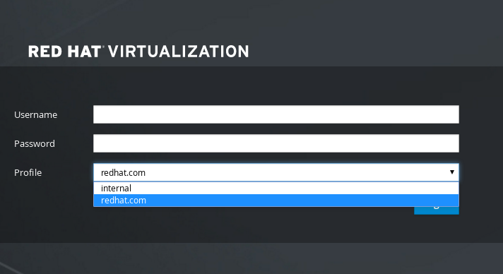
Figure 16.1. The Administration Portal Login Page
Note
Users must select the profile from the drop-down list when logging in for the first time. The information is stored in browser cookies and preselected the next time the user logs in. - Test the login function to ensure your LDAP server is connected to your Red Hat Virtualization environment properly. For the login query, enter your
user nameandpassword:NOTE: It is highly recommended to test drive the configuration before applying it into engine. Login sequence is executed automatically, but it is recommended to also execute Search sequence manually after successful Login sequence. Please provide credentials to test login flow: Enter user name: Enter user password: [ INFO ] Executing login sequence... ... [ INFO ] Login sequence executed successfully
- Check that the user details are correct. If the user details are incorrect, select
Abort:Please make sure that user details are correct and group membership meets expectations (search for PrincipalRecord and GroupRecord titles). Abort if output is incorrect. Select test sequence to execute (Done, Abort, Login, Search) [Abort]:
- Manually testing the Search function is recommended. For the search query, select
Principalfor user accounts, and selectGroupfor group accounts. SelectYestoResolve Groupsif you want the group account information for the user account to be returned. Three configuration files are created and displayed in the screen output.Select test sequence to execute (Done, Abort, Login, Search) [Search]: Search Select entity to search (Principal, Group) [Principal]: Term to search, trailing '*' is allowed: testuser1 Resolve Groups (Yes, No) [No]:
- Select
Doneto complete the setup:Select test sequence to execute (Done, Abort, Login, Search) [Abort]: Done [ INFO ] Stage: Transaction setup [ INFO ] Stage: Misc configuration [ INFO ] Stage: Package installation [ INFO ] Stage: Misc configuration [ INFO ] Stage: Transaction commit [ INFO ] Stage: Closing up CONFIGURATION SUMMARY Profile name is: redhat.com The following files were created: /etc/ovirt-engine/aaa/redhat.com.properties /etc/ovirt-engine/extensions.d/redhat.com.properties /etc/ovirt-engine/extensions.d/redhat.com-authn.properties [ INFO ] Stage: Clean up Log file is available at /tmp/ovirt-engine-extension-aaa-ldap-setup-20171004101225-mmneib.log: [ INFO ] Stage: Pre-termination [ INFO ] Stage: Termination - Restart the
ovirt-engineservice. The profile you have created is now available on the Administration Portal and the User Portal login pages. To assign the user accounts on the LDAP server appropriate roles and permissions, for example to log in to the User Portal, see Section 16.6, “Administering User Tasks From the Administration Portal”.# systemctl restart ovirt-engine.service
Note
/usr/share/doc/ovirt-engine-extension-aaa-ldap-version.
16.3.2. Attaching an Active Directory
- You need to know the Active Directory forest name. The forest name is also known as the root domain name.
Note
Examples of the most common Active Directory configurations, which cannot be configured using the ovirt-engine-extension-aaa-ldap-setup tool, are provided in/usr/share/ovirt-engine-extension-aaa-ldap/examples/README.md. - You need to either add the DNS server that can resolve the Active Directory forest name to the
/etc/resolv.conffile on the Manager, or note down the Active Directory DNS servers and enter them when prompted by the interactive setup script. - To set up secure connection between the LDAP server and the Manager, ensure a PEM-encoded CA certificate has been prepared. See Section D.2, “Setting Up SSL or TLS Connections between the Manager and an LDAP Server” for more information.
- Unless anonymous search is supported, a user with permissions to browse all users and groups must be available on the Active Directory to be used as the search user. Note down the search user's distinguished name (DN). Do not use the administrative user for the Active Directory.
- Have at least one set of account name and password ready to perform search and login queries to the Active Directory.
Procedure 16.2. Configuring an External LDAP Provider
- On the Red Hat Virtualization Manager, install the LDAP extension package:
# yum install ovirt-engine-extension-aaa-ldap-setup
- Run
ovirt-engine-extension-aaa-ldap-setupto start the interactive setup:# ovirt-engine-extension-aaa-ldap-setup
- Select an LDAP type by entering the corresponding number. The LDAP-related questions after this step are different for different LDAP types.
Available LDAP implementations:
 1 - 389ds
 2 - 389ds RFC-2307 Schema
 3 - Active Directory
 4 - IBM Security Directory Server
 5 - IBM Security Directory Server RFC-2307 Schema
 6 - IPA
 7 - Novell eDirectory RFC-2307 Schema
 8 - OpenLDAP RFC-2307 Schema
 9 - OpenLDAP Standard Schema
10 - Oracle Unified Directory RFC-2307 Schema
11 - RFC-2307 Schema (Generic)
12 - RHDS
13 - RHDS RFC-2307 Schema
14 - iPlanet
Please select: 3
- Enter the Active Directory forest name. If the forest name is not resolvable by your Manager's DNS, the script prompts you to enter a space-separated list of Active Directory DNS server names.
Please enter Active Directory Forest name: ad-example.redhat.com
[ INFO  ] Resolving Global Catalog SRV record for ad-example.redhat.com
[ INFO  ] Resolving LDAP SRV record for ad-example.redhat.com
- Select the secure connection method your LDAP server supports and specify the method to obtain a PEM-encoded CA certificate. The file option allows you to provide the full path to the certificate. The URL option allows you to specify a URL to the certificate. Use the inline option to paste the content of the certificate in the terminal. The system option allows you to specify the location for all CA files. The insecure option allows you to use startTLS in insecure mode.
NOTE:
It is highly recommended to use secure protocol to access the LDAP server.
Protocol startTLS is the standard recommended method to do so.
Only in cases in which the startTLS is not supported, fallback to non standard ldaps protocol.
Use plain for test environments only.
Please select protocol to use (startTLS, ldaps, plain) [startTLS]: startTLS
Please select method to obtain PEM encoded CA certificate (File, URL, Inline, System, Insecure): File
Please enter the password:
Note
LDAPS stands for Lightweight Directory Access Protocol Over Secure Socket Links. For SSL connections, select theldapsoption.For more information on creating a PEM-encoded CA certificate, see Section D.2, “Setting Up SSL or TLS Connections between the Manager and an LDAP Server”. - Enter the search user distinguished name (DN). The user must have permissions to browse all users and groups on the directory server. The search user must be of LDAP annotation. If anonymous search is allowed, press Enter without any input.
Enter search user DN (empty for anonymous): uid=user1,ou=Users,dc=test,dc=redhat,dc=com
Enter search user password:
- Specify a profile name. The profile name is visible to users on the login page. This example uses
redhat.com.Please specify profile name that will be visible to users:redhat.com
Figure 16.2. The Administration Portal Login Page
Note
Users need to select the desired profile from the drop-down list when logging in for the first time. The information is then stored in browser cookies and preselected the next time the user logs in. - Test the search and login function to ensure your LDAP server is connected to your Red Hat Virtualization environment properly. For the login query, enter the account name and password. For the search query, select
Principalfor user accounts, and selectGroupfor group accounts. EnterYestoResolve Groupsif you want the group account information for the user account to be returned. SelectDoneto complete the setup. Three configuration files are created and displayed in the screen output.NOTE: It is highly recommended to test drive the configuration before applying it into engine. Perform at least one Login sequence and one Search sequence. Select test sequence to execute (Done, Abort, Login, Search) [Abort]: Login Enter search user name: testuser1 Enter search user password: [ INFO ] Executing login sequence... ... Select test sequence to execute (Done, Abort, Login, Search) [Abort]: Search Select entity to search (Principal, Group) [Principal]: Term to search, trailing '*' is allowed: testuser1 Resolve Groups (Yes, No) [No]: [ INFO ] Executing login sequence... ... Select test sequence to execute (Done, Abort, Login, Search) [Abort]: Done [ INFO ] Stage: Transaction setup [ INFO ] Stage: Misc configuration [ INFO ] Stage: Package installation [ INFO ] Stage: Misc configuration [ INFO ] Stage: Transaction commit [ INFO ] Stage: Closing up CONFIGURATION SUMMARY Profile name is: redhat.com The following files were created: /etc/ovirt-engine/aaa/redhat.com.properties /etc/ovirt-engine/extensions.d/redhat.com-authz.properties /etc/ovirt-engine/extensions.d/redhat.com-authn.properties [ INFO ] Stage: Clean up Log file is available at /tmp/ovirt-engine-extension-aaa-ldap-setup-20160114064955-1yar9i.log: [ INFO ] Stage: Pre-termination [ INFO ] Stage: Termination - The profile you have created is now available on the Administration Portal and the User Portal login pages. To assign the user accounts on the LDAP server appropriate roles and permissions, for example to log in to the User Portal, see Section 16.6, “Administering User Tasks From the Administration Portal”.
Note
/usr/share/doc/ovirt-engine-extension-aaa-ldap-version.
16.3.3. Configuring an External LDAP Provider (Manual Method)
ovirt-engine-extension-aaa-ldap extension uses the LDAP protocol to access directory servers and is fully customizable. Kerberos authentication is not required unless you want to enable the single sign-on to the User Portal or the Administration Portal feature.
Procedure 16.3. Configuring an External LDAP Provider Manually
- On the Red Hat Virtualization Manager, install the LDAP extension package:
# yum install ovirt-engine-extension-aaa-ldap
- Copy the LDAP configuration template file into the
/etc/ovirt-enginedirectory. Template files are available for active directories (ad) and other directory types (simple). This example uses the simple configuration template.# cp -r /usr/share/ovirt-engine-extension-aaa-ldap/examples/simple/. /etc/ovirt-engine
- Rename the configuration files to match the profile name you want visible to users on the Administration Portal and the User Portal login pages:
# mv /etc/ovirt-engine/aaa/profile1.properties /etc/ovirt-engine/aaa/example.properties
# mv /etc/ovirt-engine/extensions.d/profile1-authn.properties /etc/ovirt-engine/extensions.d/example-authn.properties
# mv /etc/ovirt-engine/extensions.d/profile1-authz.properties /etc/ovirt-engine/extensions.d/example-authz.properties
- Edit the LDAP property configuration file by uncommenting an LDAP server type and updating the domain and passwords fields:
# vi /etc/ovirt-engine/aaa/example.properties
Example 16.1. Example profile: LDAP server section
# Select one
#
include = <openldap.properties>
#include = <389ds.properties>
#include = <rhds.properties>
#include = <ipa.properties>
#include = <iplanet.properties>
#include = <rfc2307-389ds.properties>
#include = <rfc2307-rhds.properties>
#include = <rfc2307-openldap.properties>
#include = <rfc2307-edir.properties>
#include = <rfc2307-generic.properties>

# Server
#
vars.server = ldap1.company.com

# Search user and its password.
#
vars.user = uid=search,cn=users,cn=accounts,dc=company,dc=com
vars.password = 123456

pool.default.serverset.single.server = ${global:vars.server}
pool.default.auth.simple.bindDN = ${global:vars.user}
pool.default.auth.simple.password = ${global:vars.password}
To use TLS or SSL protocol to interact with the LDAP server, obtain the root CA certificate for the LDAP server and use it to create a public keystore file. Uncomment the following lines and specify the full path to the public keystore file and the password to access the file.Note
For more information on creating a public keystore file, see Section D.2, “Setting Up SSL or TLS Connections between the Manager and an LDAP Server”.Example 16.2. Example profile: keystore section
# Create keystore, import certificate chain and uncomment
# if using tls.
pool.default.ssl.startTLS = true
pool.default.ssl.truststore.file = /full/path/to/myrootca.jks
pool.default.ssl.truststore.password = password
- Review the authentication configuration file. The profile name visible to users on the Administration Portal and the User Portal login pages is defined by
ovirt.engine.aaa.authn.profile.name. The configuration profile location must match the LDAP configuration file location. All fields can be left as default.# vi /etc/ovirt-engine/extensions.d/example-authn.properties
Example 16.3. Example authentication configuration file
ovirt.engine.extension.name = example-authn
ovirt.engine.extension.bindings.method = jbossmodule
ovirt.engine.extension.binding.jbossmodule.module = org.ovirt.engine-extensions.aaa.ldap
ovirt.engine.extension.binding.jbossmodule.class = org.ovirt.engineextensions.aaa.ldap.AuthnExtension
ovirt.engine.extension.provides = org.ovirt.engine.api.extensions.aaa.Authn
ovirt.engine.aaa.authn.profile.name = example
ovirt.engine.aaa.authn.authz.plugin = example-authz
config.profile.file.1 = ../aaa/example.properties
- Review the authorization configuration file. The configuration profile location must match the LDAP configuration file location. All fields can be left as default.
# vi /etc/ovirt-engine/extensions.d/example-authz.properties
Example 16.4. Example authorization configuration file
ovirt.engine.extension.name = example-authz
ovirt.engine.extension.bindings.method = jbossmodule
ovirt.engine.extension.binding.jbossmodule.module = org.ovirt.engine-extensions.aaa.ldap
ovirt.engine.extension.binding.jbossmodule.class = org.ovirt.engineextensions.aaa.ldap.AuthzExtension
ovirt.engine.extension.provides = org.ovirt.engine.api.extensions.aaa.Authz
config.profile.file.1 = ../aaa/example.properties
- Ensure that the ownership and permissions of the configuration profile are appropriate:
# chown ovirt:ovirt /etc/ovirt-engine/aaa/example.properties
# chmod 600 /etc/ovirt-engine/aaa/example.properties
- Restart the engine service:
# systemctl restart ovirt-engine.service
- The example profile you have created is now available on the Administration Portal and the User Portal login pages. To give the user accounts on the LDAP server appropriate permissions, for example to log in to the User Portal, see Section 16.6, “Administering User Tasks From the Administration Portal”.
Note
/usr/share/doc/ovirt-engine-extension-aaa-ldap-version.
16.3.4. Removing an External LDAP Provider
Procedure 16.4. Removing an External LDAP Provider
- Remove the LDAP provider configuration files, replacing the default name
profile1:# rm /etc/ovirt-engine/extensions.d/profile1-authn.properties # rm /etc/ovirt-engine/extensions.d/profile1-authz.properties # rm /etc/ovirt-engine/aaa/profile1.properties
- Restart the
ovirt-engineservice:# systemctl restart ovirt-engine
- In the Administration Portal, in the Users resource tab, select the users of this provider (those whose Authorization provider is
profile1-authz) and click Remove.
16.4. Configuring LDAP and Kerberos for Single Sign-on
ovirt-engine-extension-aaa-misc and ovirt-engine-extension-aaa-ldap; and two Apache modules: mod_auth_gssapi and mod_session. You can configure single sign-on that does not involve Kerberos, however this is outside the scope of this documentation.
Note
- The existing Key Distribution Center (KDC) server uses the MIT version of Kerberos 5.
- You have administrative rights to the KDC server.
- The Kerberos client is installed on the Red Hat Virtualization Manager and user machines.
- The
kadminutility is used to create Kerberos service principals andkeytabfiles.
On the KDC server
- Create a service principal and a
keytabfile for the Apache service on the Red Hat Virtualization Manager.
On the Red Hat Virtualization Manager
- Install the authentication and authorization extension packages and the Apache Kerberos authentication module.
- Configure the extension files.
Procedure 16.5. Configuring Kerberos for the Apache Service
- On the KDC server, use the
kadminutility to create a service principal for the Apache service on the Red Hat Virtualization Manager. The service principal is a reference ID to the KDC for the Apache service.# kadmin kadmin> addprinc -randkey HTTP/fqdn-of-rhevm@REALM.COM
- Generate a
keytabfile for the Apache service. Thekeytabfile stores the shared secret key.kadmin> ktadd -k /tmp/http.keytab HTTP/fqdn-of-rhevm@REALM.COM
kadmin> quit
- Copy the
keytabfile from the KDC server to the Red Hat Virtualization Manager:# scp /tmp/http.keytab root@rhevm.example.com:/etc/httpd
Procedure 16.6. Configuring Single Sign-on to the User Portal or Administration Portal
- On the Red Hat Virtualization Manager, ensure that the ownership and permissions for the keytab are appropriate:
# chown apache /etc/httpd/http.keytab
# chmod 400 /etc/httpd/http.keytab
- Install the authentication extension package, LDAP extension package, and the
mod_auth_gssapiandmod_sessionApache modules:# yum install ovirt-engine-extension-aaa-misc ovirt-engine-extension-aaa-ldap mod_auth_gssapi mod_session
- Copy the SSO configuration template file into the
/etc/ovirt-enginedirectory. Template files are available for Active Directory (ad-sso) and other directory types (simple-sso). This example uses the simple SSO configuration template.# cp -r /usr/share/ovirt-engine-extension-aaa-ldap/examples/simple-sso/. /etc/ovirt-engine
- Move
ovirt-sso.confinto the Apache configuration directory:# mv /etc/ovirt-engine/aaa/ovirt-sso.conf /etc/httpd/conf.d
- Review the authentication method file. You do not need to edit this file, as the realm is automatically fetched from the
keytabfile.# vi /etc/httpd/conf.d/ovirt-sso.conf
Example 16.5. Example authentication method file
<LocationMatch ^/ovirt-engine/sso/(interactive-login-negotiate|oauth/token-http-auth)|^/ovirt-engine/api> <If "req('Authorization') !~ /^(Bearer|Basic)/i"> RewriteEngine on RewriteCond %{LA-U:REMOTE_USER} ^(.*)$ RewriteRule ^(.*)$ - [L,NS,P,E=REMOTE_USER:%1] RequestHeader set X-Remote-User %{REMOTE_USER}s AuthType GSSAPI AuthName "Kerberos Login" # Modify to match installation GssapiCredStore keytab:/etc/httpd/http.keytab GssapiUseSessions On Session On SessionCookieName ovirt_gssapi_session path=/private;httponly;secure; Require valid-user ErrorDocument 401 "<html><meta http-equiv=\"refresh\" content=\"0; url=/ovirt-engine/sso/login-unauthorized\"/><body><a href=\"/ovirt-engine/sso/login-unauthorized\">Here</a></body></html>" </If> </LocationMatch> - Rename the configuration files to match the profile name you want visible to users on the Administration Portal and the User Portal login pages:
# mv /etc/ovirt-engine/aaa/profile1.properties /etc/ovirt-engine/aaa/example.properties
# mv /etc/ovirt-engine/extensions.d/profile1-http-authn.properties /etc/ovirt-engine/extensions.d/example-http-authn.properties
# mv /etc/ovirt-engine/extensions.d/profile1-http-mapping.properties /etc/ovirt-engine/extensions.d/example-http-mapping.properties
# mv /etc/ovirt-engine/extensions.d/profile1-authz.properties /etc/ovirt-engine/extensions.d/example-authz.properties
- Edit the LDAP property configuration file by uncommenting an LDAP server type and updating the domain and passwords fields:
# vi /etc/ovirt-engine/aaa/example.properties
Example 16.6. Example profile: LDAP server section
# Select one
include = <openldap.properties>
#include = <389ds.properties>
#include = <rhds.properties>
#include = <ipa.properties>
#include = <iplanet.properties>
#include = <rfc2307-389ds.properties>
#include = <rfc2307-rhds.properties>
#include = <rfc2307-openldap.properties>
#include = <rfc2307-edir.properties>
#include = <rfc2307-generic.properties>

# Server
#
vars.server = ldap1.company.com

# Search user and its password.
#
vars.user = uid=search,cn=users,cn=accounts,dc=company,dc=com
vars.password = 123456

pool.default.serverset.single.server = ${global:vars.server}
pool.default.auth.simple.bindDN = ${global:vars.user}
pool.default.auth.simple.password = ${global:vars.password}
To use TLS or SSL protocol to interact with the LDAP server, obtain the root CA certificate for the LDAP server and use it to create a public keystore file. Uncomment the following lines and specify the full path to the public keystore file and the password to access the file.Note
For more information on creating a public keystore file, see Section D.2, “Setting Up SSL or TLS Connections between the Manager and an LDAP Server”.Example 16.7. Example profile: keystore section
# Create keystore, import certificate chain and uncomment
# if using ssl/tls.
pool.default.ssl.startTLS = true
pool.default.ssl.truststore.file = /full/path/to/myrootca.jks
pool.default.ssl.truststore.password = password
- Review the authentication configuration file. The profile name visible to users on the Administration Portal and the User Portal login pages is defined by
ovirt.engine.aaa.authn.profile.name. The configuration profile location must match the LDAP configuration file location. All fields can be left as default.# vi /etc/ovirt-engine/extensions.d/example-http-authn.properties
Example 16.8. Example authentication configuration file
ovirt.engine.extension.name = example-http-authn
ovirt.engine.extension.bindings.method = jbossmodule
ovirt.engine.extension.binding.jbossmodule.module = org.ovirt.engine-extensions.aaa.misc
ovirt.engine.extension.binding.jbossmodule.class = org.ovirt.engineextensions.aaa.misc.http.AuthnExtension
ovirt.engine.extension.provides = org.ovirt.engine.api.extensions.aaa.Authn
ovirt.engine.aaa.authn.profile.name = example-http
ovirt.engine.aaa.authn.authz.plugin = example-authz
ovirt.engine.aaa.authn.mapping.plugin = example-http-mapping
config.artifact.name = HEADER
config.artifact.arg = X-Remote-User
- Review the authorization configuration file. The configuration profile location must match the LDAP configuration file location. All fields can be left as default.
# vi /etc/ovirt-engine/extensions.d/example-authz.properties
Example 16.9. Example authorization configuration file
ovirt.engine.extension.name = example-authz
ovirt.engine.extension.bindings.method = jbossmodule
ovirt.engine.extension.binding.jbossmodule.module = org.ovirt.engine-extensions.aaa.ldap
ovirt.engine.extension.binding.jbossmodule.class = org.ovirt.engineextensions.aaa.ldap.AuthzExtension
ovirt.engine.extension.provides = org.ovirt.engine.api.extensions.aaa.Authz
config.profile.file.1 = ../aaa/example.properties
- Review the authentication mapping configuration file. The configuration profile location must match the LDAP configuration file location. The configuration profile extension name must match the
ovirt.engine.aaa.authn.mapping.pluginvalue in the authentication configuration file. All fields can be left as default.# vi /etc/ovirt-engine/extensions.d/example-http-mapping.properties
Example 16.10. Example authentication mapping configuration file
ovirt.engine.extension.name = example-http-mapping ovirt.engine.extension.bindings.method = jbossmodule ovirt.engine.extension.binding.jbossmodule.module = org.ovirt.engine-extensions.aaa.misc ovirt.engine.extension.binding.jbossmodule.class = org.ovirt.engineextensions.aaa.misc.mapping.MappingExtension ovirt.engine.extension.provides = org.ovirt.engine.api.extensions.aaa.Mapping config.mapAuthRecord.type = regex config.mapAuthRecord.regex.mustMatch = true config.mapAuthRecord.regex.pattern = ^(?<user>.*?)((\\\\(?<at>@)(?<suffix>.*?)@.*)|(?<realm>@.*))$ config.mapAuthRecord.regex.replacement = ${user}${at}${suffix} - Ensure that the ownership and permissions of the configuration files are appropriate:
# chown ovirt:ovirt /etc/ovirt-engine/aaa/example.properties
# chown ovirt:ovirt /etc/ovirt-engine/extensions.d/example-http-authn.properties
# chown ovirt:ovirt /etc/ovirt-engine/extensions.d/example-http-mapping.properties
# chown ovirt:ovirt /etc/ovirt-engine/extensions.d/example-authz.properties
# chmod 600 /etc/ovirt-engine/aaa/example.properties
# chmod 640 /etc/ovirt-engine/extensions.d/example-http-authn.properties
# chmod 640 /etc/ovirt-engine/extensions.d/example-http-mapping.properties
# chmod 640 /etc/ovirt-engine/extensions.d/example-authz.properties
- Restart the Apache service and the
ovirt-engineservice:# systemctl restart httpd.service
# systemctl restart ovirt-engine.service
16.5. User Authorization
16.5.1. User Authorization Model
- The user performing the action
- The type of action being performed
- The object on which the action is being performed
16.5.2. User Actions
user must have the appropriate permission for the object being acted upon. Each type of action corresponds to a permission. There are many different permissions in the system, so for simplicity:

Figure 16.3. Actions
Important
16.6. Administering User Tasks From the Administration Portal
16.6.1. Adding Users and Assigning User Portal Permissions
Procedure 16.7. Adding Users and Assigning User Portal Permissions
- On the header bar, click Configure to open the Configure window. Click System Permissions.
- Click to open the Add System Permission to User window.
- Select a profile under Search. The profile is the domain you want to search. Enter a name or part of a name in the search text field, and click . Alternatively, click to view a list of all users and groups.
- Select the check boxes for the appropriate users or groups.
- Select an appropriate role to assign under Role to Assign. The role gives the user account the permission to log in to the User Portal.
- Click .
16.6.2. Viewing User Information
Procedure 16.8. Viewing User Information
- Click the Users tab to display the list of authorized users.
- Select the user, or perform a search if the user is not visible on the results list.
- The details pane displays for the selected user, usually with the General tab displaying general information, such as the domain name, email and status of the user.
- The other tabs allow you to view groups, permissions, quotas, and events for the user.For example, to view the groups to which the user belongs, click the Directory Groups tab.
16.6.3. Viewing User Permissions on Resources
Procedure 16.9. Viewing User Permissions on Resources
- Click the resource tabs, and select a resource in the results list.
- Click the Permissions tab of the details pane to list the assigned users, the user's role, and the inherited permissions for the selected resource.
16.6.4. Removing Users
Procedure 16.10. Removing Users
- Click the Users tab to display the list of authorized users.
- Select the user to be removed. Ensure the user is not running any virtual machines.
- Click the button. A message displays prompting you to confirm the removal. Click .
16.6.5. Viewing Logged-In Users
16.6.6. Terminating a User Session
Procedure 16.11. Terminating a User Session
- Click the Active User Sessions entry in the tree pane.
- Select the user session to be terminated.
- Click Terminate Session.
- Click OK.
16.7. Administering User Tasks From the Command Line
ovirt-aaa-jdbc-tool tool to manage user accounts on the internal domain. Changes made using the tool take effect immediately and do not require you to restart the ovirt-engine service. For a full list of user options, run ovirt-aaa-jdbc-tool user --help. Common examples are provided in this section.
Important
16.7.1. Creating a New User
--attribute command specifies account details. For a full list of options, run ovirt-aaa-jdbc-tool user add --help.
# ovirt-aaa-jdbc-tool user add test1 --attribute=firstName=John --attribute=lastName=Doe
adding user test1...
user added successfully
16.7.2. Setting a User Password
--password-valid-to. Otherwise, the password expiry time defaults to the current time. The date format is yyyy-MM-dd HH:mm:ssX. In this example, -0800 stands for GMT minus 8 hours. For more options, run ovirt-aaa-jdbc-tool user password-reset --help.
# ovirt-aaa-jdbc-tool user password-reset test1 --password-valid-to="2025-08-01 12:00:00-0800"
Password:
Reenter password:
updating user test1...
user updated successfully
Note
- A minimum of 6 characters.
- Three previous passwords used cannot be set again during the password change.
ovirt-aaa-jdbc-tool settings show.
16.7.3. Setting User Timeout
# engine-config --set UserSessionTimeOutInterval=integer
30 minutes. A negative value ensures that sessions never expire.
16.7.4. Pre-encrypting a User Password
ovirt-engine-crypto-tool. This option is useful if you are adding users and passwords to the database with a script.
Note
ovirt-engine-crypto-tool script is used because all passwords must be encrypted with the same algorithm.
- Run the following command:
# /usr/share/ovirt-engine/bin/ovirt-engine-crypto-tool.sh pbe-encode
The script will prompt you to enter the password.Alternatively, you can use--password=file:file, with the password in the first line of the file:# /usr/share/ovirt-engine/bin/ovirt-engine-crypto-tool.sh pbe-encode --password=file:file
- Set the new password with the
ovirt-aaa-jdbc-tooltool, using the--encryptedoption:# ovirt-aaa-jdbc-tool user password-reset test1 --password-valid-to="2025-08-01 12:00:00-0800" --encrypted
- Enter and confirm the encrypted password:
Password:
Reenter password:
updating user test1...
user updated successfully
16.7.5. Viewing User Information
# ovirt-aaa-jdbc-tool user show test1
16.7.6. Editing User Information
# ovirt-aaa-jdbc-tool user edit test1 --attribute=email=jdoe@example.com
16.7.7. Removing a User
- You can remove a user account:
# ovirt-aaa-jdbc-tool user delete test1
- Remove the user from the Administration Portal. See Section 16.6.4, “Removing Users” for more information.
16.7.8. Disabling the Internal Administrative User
admin@internal user created during engine-setup. Make sure you have at least one user in the environment with full administrative permissions before disabling the default admin user. See Section 16.6.1, “Adding Users and Assigning User Portal Permissions” for more information.
# ovirt-aaa-jdbc-tool user edit admin --flag=+disabledNote
ovirt-aaa-jdbc-tool user edit username --flag=-disabled
16.7.9. Managing Groups
ovirt-aaa-jdbc-tool group --help. Common examples are provided in this section.
# ovirt-aaa-jdbc-tool group add group1
# ovirt-aaa-jdbc-tool group-manage useradd group1 --user=test1
Note
ovirt-aaa-jdbc-tool group-manage --help.
# ovirt-aaa-jdbc-tool group show group1
- Create the first group:
# ovirt-aaa-jdbc-tool group add group1
- Create the second group:
# ovirt-aaa-jdbc-tool group add group1-1
- Add the second group to the first group:
# ovirt-aaa-jdbc-tool group-manage groupadd group1 --group=group1-1
- Add the first group in the Administration Portal and assign the group appropriate roles and permissions. See Section 16.6.1, “Adding Users and Assigning User Portal Permissions” for more information.
16.7.10. Querying Users and Groups
query module. For a full list of options, run ovirt-aaa-jdbc-tool query --help.
# ovirt-aaa-jdbc-tool query --what=user
# ovirt-aaa-jdbc-tool query --what=group
j:
# ovirt-aaa-jdbc-tool query --what=user --pattern="name=j*"
# ovirt-aaa-jdbc-tool query --what=group --pattern="department=marketing"
16.7.11. Managing Account Settings
settings module. To view all options, run ovirt-aaa-jdbc-tool settings show.
10080 minutes) to 60 minutes for all user accounts:
# ovirt-aaa-jdbc-tool settings set --name=MAX_LOGIN_MINUTES --value=60
5) a user can perform before the user account is locked:
# ovirt-aaa-jdbc-tool settings set --name=MAX_FAILURES_SINCE_SUCCESS --value=3
Note
ovirt-aaa-jdbc-tool user unlock test1.
16.8. Configuring Additional Local Domains
internal domain is supported. This can be done using the ovirt-engine-extension-aaa-jdbc extension and allows you to create multiple domains without attaching external directory servers, though the use case may not be common for enterprise environments.
/usr/share/doc/ovirt-engine-extension-aaa-jdbc-version/README.admin.
Chapter 17. Quotas and Service Level Agreement Policy
17.1. Introduction to Quota
| Quota type | Definition |
|---|---|
| Run-time Quota | This quota limits the consumption of runtime resources, like CPU and memory. |
| Storage Quota | This quota limits the amount of storage available. |
| Quota Mode | Function |
|---|---|
| Enforced | This mode puts into effect the Quota that you have set in audit mode, limiting resources to the group or user affected by the quota. |
| Audit | This mode allows you to change Quota settings. Choose this mode to increase or decrease the amount of runtime quota and the amount of storage quota available to users affected by it. |
| Disabled | This mode turns off the runtime and storage limitations defined by the quota. |
Important
17.3. Quota Accounting
Example 17.1. Accounting example
17.4. Enabling and Changing a Quota Mode in a Data Center
Procedure 17.1. Enabling and Changing Quota in a Data Center
- Click the Data Centers tab in the Navigation Pane.
- From the list of data centers displayed in the Navigation Pane, choose the data center whose quota policy you plan to edit.
- Click in the top left of the Navigation Pane.An Edit Data Center window opens.
- In the Quota Mode drop-down, change the quota mode to Enforced.
- Click OK.
17.5. Creating a New Quota Policy
Procedure 17.2. Creating a New Quota Policy
- In tree mode, select the data center. The Quota tab appears in the Navigation Pane.
- Click the Quota tab in the Navigation Pane.
- Click in the Navigation Pane. The New Quota window opens.
- Fill in the Name field with a meaningful name.Fill in the Description field with a meaningful name.
- In the Memory & CPU section of the New Quota window, use the green slider to set Cluster Threshold.
- In the Memory & CPU section of the New Quota window, use the blue slider to set Cluster Grace.
- Select the All Clusters or the Specific Clusters radio button. If you select Specific Clusters, select the check box of the clusters that you want to add a quota policy to.
- Click to open the Edit Quota window.
- Under the Memory field, select either the Unlimited radio button (to allow limitless use of Memory resources in the cluster), or select the limit to radio button to set the amount of memory set by this quota. If you select the limit to radio button, input a memory quota in megabytes (MB) in the MB field.
- Under the CPU field, select either the Unlimited radio button or the limit to radio button to set the amount of CPU set by this quota. If you select the limit to radio button, input a number of vCPUs in the vCpus field.
- Click in the Edit Quota window.
- In the Storage section of the New Quota window, use the green slider to set Storage Threshold.
- In the Storage section of the New Quota window, use the blue slider to set Storage Grace.
- Select the All Storage Domains or the Specific Storage Domains radio button. If you select Specific Storage Domains, select the check box of the storage domains that you want to add a quota policy to.
- Click to open the Edit Quota window.
- Under the Storage Quota field, select either the Unlimited radio button (to allow limitless use of Storage) or the limit to radio button to set the amount of storage to which quota will limit users. If you select the limit to radio button, input a storage quota size in gigabytes (GB) in the GB field.
- Click in the Edit Quota window. You are returned to the New Quota window.
- Click in the New Quota window.
You have created a new quota policy.
17.6. Explanation of Quota Threshold Settings
| Setting | Definition |
|---|---|
| Cluster Threshold | The amount of cluster resources available per data center. |
| Cluster Grace | The amount of the cluster available for the data center after exhausting the data center's Cluster Threshold. |
| Storage Threshold | The amount of storage resources available per data center. |
| Storage Grace | The amount of storage available for the data center after exhausting the data center's Storage Threshold. |
17.7. Assigning a Quota to an Object
This procedure explains how to associate a virtual machine with a quota.
Procedure 17.3. Assigning a Quota to a Virtual Machine
- In the navigation pane, select the Virtual Machine to which you plan to add a quota.
- Click . The Edit Virtual Machine window appears.
- Select the quota you want the virtual machine to consume. Use the Quota drop-down to do this.
- Click .
You have designated a quota for the virtual machine you selected.
This procedure explains how to associate a virtual disk with a quota.
Procedure 17.4. Assigning a Quota to a Virtual Disk
- In the navigation pane, select the Virtual Machine whose disk(s) you plan to add a quota.
- In the details pane, select the disk you plan to associate with a quota.
- Click . The Edit Virtual Disk window appears.
- Select the quota you want the virtual disk to consume.
- Click .
You have designated a quota for the virtual disk you selected.
Important
17.8. Using Quota to Limit Resources by User
This procedure describes how to use quotas to limit the resources a user has access to.
Procedure 17.5. Assigning a User to a Quota
- In the tree, click the Data Center with the quota you want to associate with a User.
- Click the Quota tab in the navigation pane.
- Select the target quota in the list in the navigation pane.
- Click the tab in the details pane.
- Click at the top of the details pane.
- In the Search field, type the name of the user you want to associate with the quota.
- Click .
- Select the check box at the left side of the row containing the name of the target user.
- Click in the bottom right of the Assign Users and Groups to Quota window.
After a short time, the user will appear in the Consumers tab of the details pane.
17.9. Editing Quotas
This procedure describes how to change existing quotas.
Procedure 17.6. Editing Quotas
- On the tree pane, click on the data center whose quota you want to edit.
- Click on the Quota tab in the Navigation Pane.
- Click the name of the quota you want to edit.
- Click Edit in the Navigation pane.
- An Edit Quota window opens. If required, enter a meaningful name in the Name field.
- If required, you can enter a meaningful description in the Description field.
- Select either the All Clusters radio button or the Specific Clusters radio button. Move the Cluster Threshold and Cluster Grace sliders to the desired positions on the Memory & CPU slider.
- Select either the All Storage Domains radio button or the Specific Storage Domains radio button. Move the Storage Threshold and Storage Grace sliders to the desired positions on the Storage slider.
- Click in the Edit Quota window to confirm the new quota settings.
You have changed an existing quota.
17.10. Removing Quotas
This procedure describes how to remove quotas.
Procedure 17.7. Removing Quotas
- On the tree pane, click on the data center whose quota you want to edit.
- Click on the Quota tab in the Navigation Pane.
- Click the name of the quota you want to remove.
- Click at the top of the Navigation pane, under the row of tabs.
- Click in the Remove Quota(s) window to confirm the removal of this quota.
You have removed a quota.
17.11. Service Level Agreement Policy Enforcement
This procedure describes how to set service level agreement CPU features.
Procedure 17.8. Setting a Service Level Agreement CPU Policy
- Select in the Navigation Pane.
- Select .
- Select the Resource Allocation tab.
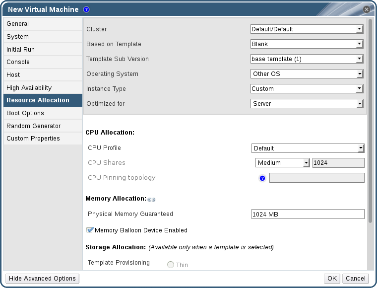
Figure 17.1. Service Level Agreement Policy Enforcement - CPU Allocation Menu
- Specify CPU Shares. Possible options are Low, Medium, High, Custom, and Disabled. Virtual machines set to High receive twice as many shares as Medium, and virtual machines set to Medium receive twice as many shares as virtual machines set to Low. Disabled instructs VDSM to use an older algorithm for determining share dispensation; usually the number of shares dispensed under these conditions is 1020.
You have set a service level agreement CPU policy. The CPU consumption of users is now governed by the policy you have set.
Chapter 18. Event Notifications
18.1. Configuring Event Notifications in the Administration Portal
Procedure 18.1. Configuring Event Notifications
- Ensure that you have access to an email server that can accept automated messages from RHVM and deliver them to a distribution list.
- Use the Users resource tab, tree mode, or the search function to find and select the user to which event notifications will be sent.
- Click the Event Notifier tab in the details pane to list the events for which the user will be notified. This list is blank if you have not configured any event notifications for that user.
- Click to open the Add Event Notification window.
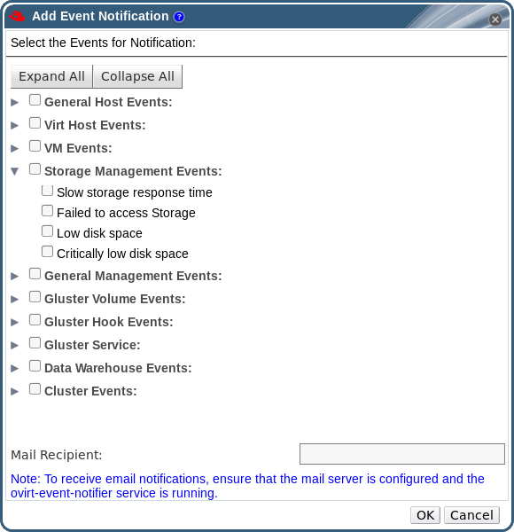
Figure 18.1. The Add Events Notification Window
- Use the button or the subject-specific expansion buttons to view the events.
- Select the appropriate check boxes.
- Enter an email address in the Mail Recipient field.
- Click to save changes and close the window.
- On the Manager machine, copy
ovirt-engine-notifier.confto a new file called90-email-notify.conf:cp /usr/share/ovirt-engine/services/ovirt-engine-notifier/ovirt-engine-notifier.conf /etc/ovirt-engine/notifier/notifier.conf.d/90-email-notify.conf
- Edit
90-email-notify.conf, deleting everything except theEMAIL Notificationssection. - Enter the correct email variables, as in the example below. This file overrides the values in the original
ovirt-engine-notifier.conffile.#---------------------# # EMAIL Notifications # #---------------------# # The SMTP mail server address. Required. MAIL_SERVER=myemailserver.example.com # The SMTP port (usually 25 for plain SMTP, 465 for SMTP with SSL, 587 for SMTP with TLS) MAIL_PORT=25 # Required if SSL or TLS enabled to authenticate the user. Used also to specify 'from' user address if mail server # supports, when MAIL_FROM is not set. Address is in RFC822 format MAIL_USER= # Required to authenticate the user if mail server requires authentication or if SSL or TLS is enabled SENSITIVE_KEYS="${SENSITIVE_KEYS},MAIL_PASSWORD" MAIL_PASSWORD= # Indicates type of encryption (none, ssl or tls) should be used to communicate with mail server. MAIL_SMTP_ENCRYPTION=none # If set to true, sends a message in HTML format. HTML_MESSAGE_FORMAT=false # Specifies 'from' address on sent mail in RFC822 format, if supported by mail server. MAIL_FROM=rhevm2017@example.com # Specifies 'reply-to' address on sent mail in RFC822 format. MAIL_REPLY_TO= # Interval to send smtp messages per # of IDLE_INTERVAL MAIL_SEND_INTERVAL=1 # Amount of times to attempt sending an email before failing. MAIL_RETRIES=4Note
See/etc/ovirt-engine/notifier/notifier.conf.d/READMEfor more options. - Enable and restart the ovirt-engine-notifier service to activate the changes you have made:
# systemctl daemon-reload# systemctl enable ovirt-engine-notifier.service# systemctl restart ovirt-engine-notifier.service
18.2. Canceling Event Notifications in the Administration Portal
A user has configured some unnecessary email notifications and wants them canceled.
Procedure 18.2. Canceling Event Notifications
- In the Users tab, select the user or the user group.
- Select the Event Notifier tab in the details pane to list events for which the user receives email notifications.
- Click to open the Add Event Notification window.
- Use the button, or the subject-specific expansion buttons, to view the events.
- Clear the appropriate check boxes to remove notification for that event.
- Click to save changes and close the window.
You have canceled unnecessary event notifications for the user.
18.3. Parameters for Event Notifications in ovirt-engine-notifier.conf
/usr/share/ovirt-engine/services/ovirt-engine-notifier/ovirt-engine-notifier.conf.
| Variable Name | Default | Remarks |
|---|---|---|
| SENSITIVE_KEYS | none | A comma-separated list of keys that will not be logged. |
| JBOSS_HOME | /opt/rh/eap7/root/usr/share/wildfly | The location of the JBoss application server used by the Manager. |
| ENGINE_ETC | /etc/ovirt-engine | The location of the etc directory used by the Manager. |
| ENGINE_LOG | /var/log/ovirt-engine | The location of the logs directory used by the Manager. |
| ENGINE_USR | /usr/share/ovirt-engine | The location of the usr directory used by the Manager. |
| ENGINE_JAVA_MODULEPATH | ${ENGINE_USR}/modules | The file path to which the JBoss modules are appended. |
| NOTIFIER_DEBUG_ADDRESS | none | The address of a machine that can be used to perform remote debugging of the Java virtual machine that the notifier uses. |
| NOTIFIER_STOP_TIME | 30 | The time, in seconds, after which the service will time out. |
| NOTIFIER_STOP_INTERVAL | 1 | The time, in seconds, by which the timeout counter will be incremented. |
| INTERVAL_IN_SECONDS | 120 | The interval in seconds between instances of dispatching messages to subscribers. |
| IDLE_INTERVAL | 30 | The interval, in seconds, between which low-priority tasks will be performed. |
| DAYS_TO_KEEP_HISTORY | 0 | This variable sets the number of days dispatched events will be preserved in the history table. If this variable is not set, events remain on the history table indefinitely. |
| FAILED_QUERIES_NOTIFICATION_THRESHOLD | 30 | The number of failed queries after which a notification email is sent. A notification email is sent after the first failure to fetch notifications, and then once every time the number of failures specified by this variable is reached. If you specify a value of 0 or 1, an email will be sent with each failure. |
| FAILED_QUERIES_NOTIFICATION_RECIPIENTS | none | The email addresses of the recipients to which notification emails will be sent. Email addresses must be separated by a comma. This entry has been deprecated by the FILTER variable. |
| DAYS_TO_SEND_ON_STARTUP | 0 | The number of days of old events that will be processed and sent when the notifier starts. |
| FILTER | exclude:* | The algorithm used to determine the triggers for and recipients of email notifications. The value for this variable comprises a combination of include or exclude, the event, and the recipient. For example, include:VDC_START(smtp:mail@example.com) ${FILTER} |
| MAIL_SERVER | none | The SMTP mail server address. Required. |
| MAIL_PORT | 25 | The port used for communication. Possible values include 25 for plain SMTP, 465 for SMTP with SSL, and 587 for SMTP with TLS. |
| MAIL_USER | none | If SSL is enabled to authenticate the user, then this variable must be set. This variable is also used to specify the "from" user address when the MAIL_FROM variable is not set. Some mail servers do not support this functionality. The address is in RFC822 format. |
| SENSITIVE_KEYS | ${SENSITIVE_KEYS},MAIL_PASSWORD | Required to authenticate the user if the mail server requires authentication or if SSL or TLS is enabled. |
| MAIL_PASSWORD | none | Required to authenticate the user if the mail server requires authentication or if SSL or TLS is enabled. |
| MAIL_SMTP_ENCRYPTION | none | The type of encryption to be used in communication. Possible values are none, ssl, tls. |
| HTML_MESSAGE_FORMAT | false | The mail server sends messages in HTML format if this variable is set to true. |
| MAIL_FROM | none | This variable specifies a sender address in RFC822 format, if supported by the mail server. |
| MAIL_REPLY_TO | none | This variable specifies reply-to addresses in RFC822 format on sent mail, if supported by the mail server. |
| MAIL_SEND_INTERVAL | 1 | The number of SMTP messages to be sent for each IDLE_INTERVAL |
| MAIL_RETRIES | 4 | The number of times to attempt to send an email before failing. |
| SNMP_MANAGER | none | The IP addresses or fully qualified domain names of machines that will act as the SNMP managers. Entries must be separated by a space and can contain a port number. For example, manager1.example.com manager2.example.com:164 |
| SNMP_COMMUNITY | public | The default SNMP community. |
| SNMP_OID | 1.3.6.1.4.1.2312.13.1.1 | The default trap object identifiers for alerts. All trap types are sent, appended with event information, to the SNMP manager when this OID is defined. Note that changing the default trap prevents generated traps from complying with the Manager's management information base. |
| ENGINE_INTERVAL_IN_SECONDS | 300 | The interval, in seconds, between monitoring the machine on which the Manager is installed. The interval is measured from the time the monitoring is complete. |
| ENGINE_MONITOR_RETRIES | 3 | The number of times the notifier attempts to monitor the status of the machine on which the Manager is installed in a given interval after a failure. |
| ENGINE_TIMEOUT_IN_SECONDS | 30 | The time, in seconds, to wait before the notifier attempts to monitor the status of the machine on which the Manager is installed in a given interval after a failure. |
| IS_HTTPS_PROTOCOL | false | This entry must be set to true if JBoss is being run in secured mode. |
| SSL_PROTOCOL | TLS | The protocol used by JBoss configuration connector when SSL is enabled. |
| SSL_IGNORE_CERTIFICATE_ERRORS | false | This value must be set to true if JBoss is running in secure mode and SSL errors is to be ignored. |
| SSL_IGNORE_HOST_VERIFICATION | false | This value must be set to true if JBoss is running in secure mode and host name verification is to be ignored. |
| REPEAT_NON_RESPONSIVE_NOTIFICATION | false | This variable specifies whether repeated failure messages will be sent to subscribers if the machine on which the Manager is installed is non-responsive. |
| ENGINE_PID | /var/lib/ovirt-engine/ovirt-engine.pid | The path and file name of the PID of the Manager. |
18.4. Configuring the Red Hat Virtualization Manager to Send SNMP Traps
- The IP addresses or fully qualified domain names of machines that will act as SNMP managers. Optionally, determine the port through which the manager receives trap notifications; by default, this is UDP port 162.
- The SNMP community. Multiple SNMP managers can belong to a single community. Management systems and agents can communicate only if they are within the same community. The default community is
public. - The trap object identifier for alerts. The Red Hat Virtualization Manager provides a default OID of 1.3.6.1.4.1.2312.13.1.1. All trap types are sent, appended with event information, to the SNMP manager when this OID is defined. Note that changing the default trap prevents generated traps from complying with the Manager's management information base.
Note
/usr/share/doc/ovirt-engine/mibs/OVIRT-MIB.txt and /usr/share/doc/ovirt-engine/mibs/REDHAT-MIB.txt. Load the MIBs in your SNMP manager before proceeding.
/usr/share/ovirt-engine/services/ovirt-engine-notifier/ovirt-engine-notifier.conf. The values outlined in the following procedure are based on the default or example values provided in that file. It is recommended that you define an override file, rather than edit the ovirt-engine-notifier.conf file, to persist your configuration options across system changes, like upgrades.
Procedure 18.3. Configuring SNMP Traps on the Manager
- On the Manager, create the SNMP configuration file:
# vi /etc/ovirt-engine/notifier/notifier.conf.d/20-snmp.conf
- Specify the SNMP manager(s), the SNMP community, and the OID in the following format:
SNMP_MANAGERS="manager1.example.com manager2.example.com:162"
SNMP_COMMUNITY=public
SNMP_OID=1.3.6.1.4.1.2312.13.1.1
- Define which events to send to the SNMP manager:
Example 18.1. Event Examples
Send all events to the default SNMP profile:FILTER="include:*(snmp:) ${FILTER}"Send all events with the severityERRORorALERTto the default SNMP profile:FILTER="include:*:ERROR(snmp:) ${FILTER}"FILTER="include:*:ALERT(snmp:) ${FILTER}"Send events for VDC_START to the specified email address:FILTER="include:VDC_START(snmp:mail@example.com) ${FILTER}"Send events for everything but VDC_START to the default SNMP profile:FILTER="exclude:VDC_START include:*(snmp:) ${FILTER}"This the default filter defined inovirt-engine-notifier.conf; if you do not disable this filter or apply overriding filters, no notifications will be sent:FILTER="exclude:*"
VDC_STARTis an example of the audit log messages available. A full list of audit log messages can be found in/usr/share/doc/ovirt-engine/AuditLogMessages.properties. Alternatively, filter results within your SNMP manager. - Save the file.
- Start the
ovirt-engine-notifierservice, and ensure that this service starts on boot:# systemctl start ovirt-engine-notifier.service # systemctl enable ovirt-engine-notifier.service
Note
SNMP_MANAGERS, MAIL_SERVER, or both must be properly defined in /usr/share/ovirt-engine/services/ovirt-engine-notifier/ovirt-engine-notifier.conf or in an override file in order for the notifier service to run.
Chapter 19. Utilities
19.1. The oVirt Engine Rename Tool
19.1.1. The oVirt Engine Rename Tool
engine-setup command is run in a clean environment, the command generates a number of certificates and keys that use the fully qualified domain name of the Manager supplied during the setup process. If the fully qualified domain name of the Manager must be changed later on (for example, due to migration of the machine hosting the Manager to a different domain), the records of the fully qualified domain name must be updated to reflect the new name. The ovirt-engine-rename command automates this task.
ovirt-engine-rename command updates records of the fully qualified domain name of the Manager in the following locations:
- /etc/ovirt-engine/engine.conf.d/10-setup-protocols.conf
- /etc/ovirt-engine/imageuploader.conf.d/10-engine-setup.conf
- /etc/ovirt-engine/isouploader.conf.d/10-engine-setup.conf
- /etc/ovirt-engine/logcollector.conf.d/10-engine-setup.conf
- /etc/pki/ovirt-engine/cert.conf
- /etc/pki/ovirt-engine/cert.template
- /etc/pki/ovirt-engine/certs/apache.cer
- /etc/pki/ovirt-engine/keys/apache.key.nopass
- /etc/pki/ovirt-engine/keys/apache.p12
Warning
ovirt-engine-rename command creates a new certificate for the web server on which the Manager runs, it does not affect the certificate for the engine or the certificate authority. Due to this, there is some risk involved in using the ovirt-engine-rename command, particularly in environments that have been upgraded from Red Hat Enterprise Virtualization 3.2 and earlier. Therefore, changing the fully qualified domain name of the Manager by running engine-cleanup and engine-setup is recommended where possible.
19.1.2. Syntax for the oVirt Engine Rename Command
ovirt-engine-rename command is:
# /usr/share/ovirt-engine/setup/bin/ovirt-engine-rename
--newname=[new name]- Allows you to specify the new fully qualified domain name for the Manager without user interaction.
--log=[file]- Allows you to specify the path and name of a file into which logs of the rename operation are to be written.
--config=[file]- Allows you to specify the path and file name of a configuration file to load into the rename operation.
--config-append=[file]- Allows you to specify the path and file name of a configuration file to append to the rename operation. This option can be used to specify the path and file name of an answer file.
--generate-answer=[file]- Allows you to specify the path and file name of a file into which your answers to and the values changed by the
ovirt-engine-renamecommand are recorded.
19.1.3. Renaming the Manager with the oVirt Engine Rename Tool
ovirt-engine-rename command to update records of the fully qualified domain name of the Manager.
Important
ovirt-engine-rename command does not update SSL certificates, such as imageio-proxy or websocket-proxy. These must be updated manually, after running ovirt-engine-rename. See Updating SSL Certificates below.
Procedure 19.1. Renaming the Red Hat Virtualization Manager
- Prepare all DNS and other relevant records for the new fully qualified domain name.
- Update the DHCP server configuration if DHCP is used.
- Update the host name on the Manager.
- Run the following command:
# /usr/share/ovirt-engine/setup/bin/ovirt-engine-rename
- When prompted, press Enter to stop the engine service:
During execution engine service will be stopped (OK, Cancel) [OK]:
- When prompted, enter the new fully qualified domain name for the Manager:
New fully qualified server name:[new name]
ovirt-engine-rename command updates records of the fully qualified domain name of the Manager.
Procedure 19.2. Updating SSL Certificates
ovirt-engine-rename command to update the SSL certificates:
# names="websocket-proxy imageio-proxy"
# subject="$(\
    openssl x509 \
    -in /etc/pki/ovirt-engine/certs/apache.cer \
    -noout \
    -subject | \
        sed \
            's;subject= \(.*\);\1;'
  )"
# . /usr/share/ovirt-engine/bin/engine-prolog.sh
# for name in $names; do
    /usr/share/ovirt-engine/bin/pki-enroll-pkcs12.sh \
        --name="${name}" \
        --password=mypass \
        --subject="${subject}" \
        --keep-key \
        --san=DNS:"${ENGINE_FQDN}"
  done
19.2. The Engine Configuration Tool
19.2.1. The Engine Configuration Tool
Note
postgresql service is running. Changes are then applied when the ovirt-engine service is restarted.
19.2.2. Syntax for the engine-config Command
# engine-config --helpCommon tasks
- List available configuration keys
#
engine-config--list- List available configuration values
#
engine-config--all- Retrieve value of configuration key
#
engine-config--get [KEY_NAME]Replace [KEY_NAME] with the name of the preferred key to retrieve the value for the given version of the key. Use the--cverparameter to specify the configuration version of the value to be retrieved. If no version is provided, values for all existing versions are returned.- Set value of configuration key
#
engine-config--set [KEY_NAME]=[KEY_VALUE]--cver=[VERSION]Replace [KEY_NAME] with the name of the specific key to set, and replace [KEY_VALUE] with the value to be set. You must specify the [VERSION] in environments with more than one configuration version.- Restart the ovirt-engine service to load changes
- The
ovirt-engineservice needs to be restarted for your changes to take effect.# systemctl restart ovirt-engine.service
19.3. The Image Uploader Tool
19.3.1. The Image Uploader Tool
Note
IMAGETRANSFERS service to create the transfer, and the IMAGETRANSFER service to specify whether to upload or download the image. See Section 11.6.7, “Uploading and Downloading a Virtual Disk to a Storage Domain” for more information.
19.4. The USB Filter Editor
19.4.1. Installing the USB Filter Editor
usbfilter.txt policy file. The policy rules defined in this file allow or deny automatic pass-through of specific USB devices from client machines to virtual machines managed using the Red Hat Virtualization Manager. The policy file resides on the Red Hat Virtualization Manager in the following location:
/etc/ovirt-engine/usbfilter.txt
ovirt-engine service on the Red Hat Virtualization Manager server is restarted.
USBFilterEditor.msi file from the Content Delivery Network: https://rhn.redhat.com/rhn/software/channel/downloads/Download.do?cid=20703.
Procedure 19.3. Installing the USB Filter Editor
- On a Windows machine, launch the
USBFilterEditor.msiinstaller obtained from the Content Delivery Network. - Follow the steps of the installation wizard. Unless otherwise specified, the USB Filter Editor will be installed by default in either
C:\Program Files\RedHat\USB Filter EditororC:\Program Files(x86)\RedHat\USB Filter Editordepending on your version of Windows. - A USB Filter Editor shortcut icon is created on your desktop.
Important
19.4.2. The USB Filter Editor Interface
- Double-click the USB Filter Editor shortcut icon on your desktop.
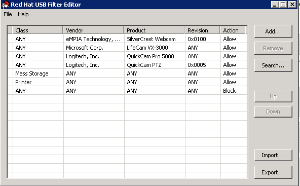
Figure 19.1. Red Hat USB Filter Editor
| Name | Description |
|---|---|
| Class | Type of USB device; for example, printers, mass storage controllers. |
| Vendor | The manufacturer of the selected type of device. |
| Product | The specific USB device model. |
| Revision | The revision of the product. |
| Action | Allow or block the specified device. |
19.4.3. Adding a USB Policy
Add a USB policy to the USB Filter Editor.
Procedure 19.4. Adding a USB Policy
- Click the button. The Edit USB Criteria window opens:
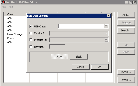
Figure 19.2. Edit USB Criteria
- Use the USB Class, Vendor ID, Product ID, and Revision check boxes and lists to specify the device.Click the button to permit virtual machines use of the USB device; click the button to prohibit the USB device from virtual machines.Click to add the selected filter rule to the list and close the window.
Example 19.1. Adding a Device
The following is an example of how to add USB ClassSmartcard, deviceEP-1427X-2 Ethernet Adapter, from manufacturerAcer Communications & Multimediato the list of allowed devices.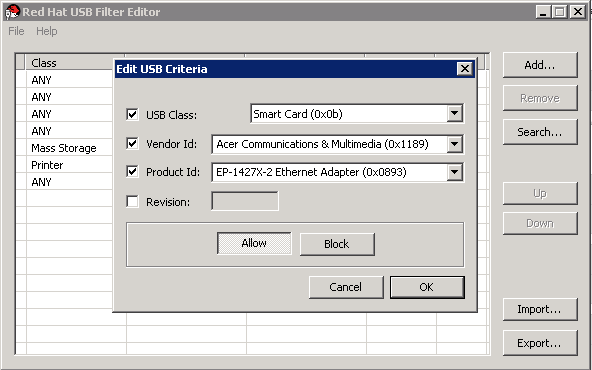
- Click → to save the changes.
You have added a USB policy to the USB Filter Editor. USB filter policies need to be exported to the Red Hat Virtualization Manager to take effect.
19.4.4. Removing a USB Policy
Remove a USB policy from the USB Filter Editor.
Procedure 19.5. Removing a USB Policy
- Select the policy to be removed.
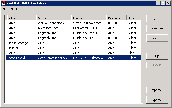
Figure 19.3. Select USB Policy
- Click . A message displays prompting you to confirm that you want to remove the policy.
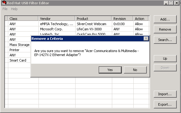
Figure 19.4. Edit USB Criteria
- Click to confirm that you want to remove the policy.
- Click → to save the changes.
You have removed a USB policy from the USB Filter Editor. USB filter policies need to be exported to the Red Hat Virtualization Manager to take effect.
19.4.5. Searching for USB Device Policies
Search for attached USB devices to either allow or block them in the USB Filter Editor.
Procedure 19.6. Searching for USB Device Policies
- Click . The Attached USB Devices window displays a list of all the attached devices.

Figure 19.5. Attached USB Devices
- Select the device and click or as appropriate. Double-click the selected device to close the window. A policy rule for the device is added to the list.
- Use the Up and Down buttons to change the position of the new policy rule in the list.
- Click → to save the changes.
You have searched the attached USB devices. USB filter policies need to be exported to the Red Hat Virtualization Manager to take effect.
19.4.6. Exporting a USB Policy
USB device policy changes need to be exported and uploaded to the Red Hat Virtualization Manager for the updated policy to take effect. Upload the policy and restart the ovirt-engine service.
Procedure 19.7. Exporting a USB Policy
- Click ; the window opens.
- Save the file with a file name of
usbfilter.txt. - Using a Secure Copy client, such as WinSCP, upload the
usbfilter.txtfile to the server running Red Hat Virtualization Manager. The file must be placed in the following directory on the server:/etc/ovirt-engine/ - As the
rootuser on the server running Red Hat Virtualization Manager, restart theovirt-engineservice.# systemctl restart ovirt-engine.service
The USB device policy will now be implemented on virtual machines running in the Red Hat Virtualization environment.
19.4.7. Importing a USB Policy
An existing USB device policy must be downloaded and imported into the USB Filter Editor before you can edit it.
Procedure 19.8. Importing a USB Policy
- Using a Secure Copy client, such as WinSCP, download the
usbfilter.txtfile from the server running Red Hat Virtualization Manager. The file can be found in the following directory on the server:/etc/ovirt-engine/ - Double-click the USB Filter Editor shortcut icon on your desktop to open the editor.
- Click to open the window.
- Open the
usbfilter.txtfile that was downloaded from the server.
You are able to edit the USB device policy in the USB Filter Editor.
19.5. The Log Collector Tool
19.5.1. Log Collector
ovirt-log-collector. You are required to log in as the root user and provide the administration credentials for the Red Hat Virtualization environment. The ovirt-log-collector -h command displays usage information, including a list of all valid options for the ovirt-log-collector command.
19.5.2. Syntax for the ovirt-log-collector Command
ovirt-log-collector[options]list[all, clusters, datacenters]ovirt-log-collector[options]collect
list and collect.
- The
listparameter lists either the hosts, clusters, or data centers attached to the Red Hat Virtualization Manager. You are able to filter the log collection based on the listed objects. - The
collectparameter performs log collection from the Red Hat Virtualization Manager. The collected logs are placed in an archive file under the/tmp/logcollectordirectory. Theovirt-log-collectorcommand assigns each log a specific file name.
ovirt-log-collector command.
General options
--version- Displays the version number of the command in use and returns to prompt.
-h,--help- Displays command usage information and returns to prompt.
--conf-file=PATH- Sets PATH as the configuration file the tool is to use.
--local-tmp=PATH- Sets PATH as the directory in which logs are saved. The default directory is
/tmp/logcollector. --ticket-number=TICKET- Sets TICKET as the ticket, or case number, to associate with the SOS report.
--upload=FTP_SERVER- Sets FTP_SERVER as the destination for retrieved logs to be sent using FTP. Do not use this option unless advised to by a Red Hat support representative.
--log-file=PATH- Sets PATH as the specific file name the command should use for the log output.
--quiet- Sets quiet mode, reducing console output to a minimum. Quiet mode is off by default.
-v,--verbose- Sets verbose mode, providing more console output. Verbose mode is off by default.
--time-only- Displays only information about time differences between hosts, without generating a full SOS report.
Red Hat Virtualization Manager Options
ovirt-log-collector --user=admin@internal --cluster ClusterA,ClusterB --hosts "SalesHost"* specifies the user as admin@internal and limits the log collection to only SalesHost hosts in clusters A and B.
--no-hypervisors- Omits virtualization hosts from the log collection.
--one-hypervisor-per-cluster- Collects the logs of one host (the SPM, if there is one) from each cluster.
-u USER,--user=USER- Sets the user name for login. The USER is specified in the format user@domain, where user is the user name and domain is the directory services domain in use. The user must exist in directory services and be known to the Red Hat Virtualization Manager.
-r FQDN,--rhevm=FQDN- Sets the fully qualified domain name of the Red Hat Virtualization Manager server from which to collect logs, where FQDN is replaced by the fully qualified domain name of the Manager. It is assumed that the log collector is being run on the same local host as the Red Hat Virtualization Manager; the default value is
localhost. -c CLUSTER,--cluster=CLUSTER- Collects logs from the virtualization hosts in the nominated CLUSTER in addition to logs from the Red Hat Virtualization Manager. The cluster(s) for inclusion must be specified in a comma-separated list of cluster names or match patterns.
-d DATACENTER,--data-center=DATACENTER- Collects logs from the virtualization hosts in the nominated DATACENTER in addition to logs from the Red Hat Virtualization Manager. The data center(s) for inclusion must be specified in a comma-separated list of data center names or match patterns.
-H HOSTS_LIST,--hosts=HOSTS_LIST- Collects logs from the virtualization hosts in the nominated HOSTS_LIST in addition to logs from the Red Hat Virtualization Manager. The hosts for inclusion must be specified in a comma-separated list of host names, fully qualified domain names, or IP addresses. Match patterns are also valid.
SSH Configuration
--ssh-port=PORT- Sets PORT as the port to use for SSH connections with virtualization hosts.
-k KEYFILE,--key-file=KEYFILE- Sets KEYFILE as the public SSH key to be used for accessing the virtualization hosts.
--max-connections=MAX_CONNECTIONS- Sets MAX_CONNECTIONS as the maximum concurrent SSH connections for logs from virtualization hosts. The default is
10.
PostgreSQL Database Options
pg-user and dbname parameters, if they have been changed from the default values.
pg-dbhost parameter if the database is not on the local host. Use the optional pg-host-key parameter to collect remote logs. The PostgreSQL SOS plugin must be installed on the database server for remote log collection to be successful.
--no-postgresql- Disables collection of database. The log collector will connect to the Red Hat Virtualization Manager PostgreSQL database and include the data in the log report unless the
--no-postgresqlparameter is specified. --pg-user=USER- Sets USER as the user name to use for connections with the database server. The default is
postgres. --pg-dbname=DBNAME- Sets DBNAME as the database name to use for connections with the database server. The default is
rhevm. --pg-dbhost=DBHOST- Sets DBHOST as the host name for the database server. The default is
localhost. --pg-host-key=KEYFILE- Sets KEYFILE as the public identity file (private key) for the database server. This value is not set by default; it is required only where the database does not exist on the local host.
19.5.3. Basic Log Collector Usage
ovirt-log-collector command is run without specifying any additional parameters, its default behavior is to collect all logs from the Red Hat Virtualization Manager and its attached hosts. It will also collect database logs unless the --no-postgresql parameter is added. In the following example, log collector is run to collect all logs from the Red Hat Virtualization Manager and three attached hosts.
Example 19.2. Log Collector Usage
# ovirt-log-collector
INFO: Gathering oVirt Engine information...
INFO: Gathering PostgreSQL the oVirt Engine database and log files from localhost...
Please provide REST API password for the admin@internal oVirt Engine user (CTRL+D to abort):
About to collect information from 3 hypervisors. Continue? (Y/n):
INFO: Gathering information from selected hypervisors...
INFO: collecting information from 192.168.122.250
INFO: collecting information from 192.168.122.251
INFO: collecting information from 192.168.122.252
INFO: finished collecting information from 192.168.122.250
INFO: finished collecting information from 192.168.122.251
INFO: finished collecting information from 192.168.122.252
Creating compressed archive...
INFO Log files have been collected and placed in /tmp/logcollector/sosreport-rhn-account-20110804121320-ce2a.tar.xz.
The MD5 for this file is 6d741b78925998caff29020df2b2ce2a and its size is 26.7M
19.6. The ISO Uploader Tool
19.6.1. The ISO Uploader Tool
engine-iso-uploader. You must log in as the root user and provide the administration credentials for the Red Hat Virtualization environment to use this command. The engine-iso-uploader -h command displays usage information, including a list of all valid options for the engine-iso-uploader command.
19.6.2. Syntax for the engine-iso-uploader Command
engine-iso-uploader[options]listengine-iso-uploader[options]upload[file].[file]...[file]
list, and upload.
- The
listaction lists the ISO storage domains to which ISO files can be uploaded. The Red Hat Virtualization Manager creates this list on the machine on which the Manager is installed during the installation process. - The
uploadaction uploads a single ISO file or multiple ISO files separated by spaces to the specified ISO storage domain. NFS is used by default, but SSH is also available.
upload action.
engine-iso-uploader command.
General Options
--version- Displays the version of the ISO uploader command.
-h,--help- Displays information on how to use the ISO uploader command.
--conf-file=[PATH]- Sets [PATH] as the configuration file the command will to use. The default is
/etc/ovirt-engine/isouploader.conf. --log-file=[PATH]- Sets [PATH] as the specific file name the command will use to write log output. The default is
/var/log/ovirt-engine/ovirt-iso-uploader/ovirt-iso-uploader[date].log. --cert-file=[PATH]- Sets [PATH] as the certificate for validating the engine. The default is
/etc/pki/ovirt-engine/ca.pem. --insecure- Specifies that no attempt will be made to verify the engine.
--nossl- Specifies that SSL will not be used to connect to the engine.
--quiet- Sets quiet mode, reducing console output to a minimum.
-v,--verbose- Sets verbose mode, providing more console output.
-f,--force- Force mode is necessary when the source file being uploaded has the same file name as an existing file in the destination ISO domain. This option forces the existing file to be overwritten.
Red Hat Virtualization Manager Options
-u [USER],--user=[USER]- Specifies the user whose credentials will be used to execute the command. The [USER] is specified in the format [username]@[domain]. The user must exist in the specified domain and be known to the Red Hat Virtualization Manager.
-r [FQDN],--engine=[FQDN]- Specifies the IP address or fully qualified domain name of the Red Hat Virtualization Manager from which the images will be uploaded. It is assumed that the image uploader is being run from the same machine on which the Red Hat Virtualization Manager is installed. The default value is
localhost:443.
ISO Storage Domain Options
-i option or the -n option.
-i,--iso-domain=[ISODOMAIN]- Sets the storage domain [ISODOMAIN] as the destination for uploads.
-n,--nfs-server=[NFSSERVER]- Sets the NFS path [NFSSERVER] as the destination for uploads.
Connection Options
--ssh-user=[USER]- Sets [USER] as the SSH user name to use for the upload. The default is
root. --ssh-port=[PORT]- Sets [PORT] as the port to use when connecting to SSH.
-k [KEYFILE],--key-file=[KEYFILE]- Sets [KEYFILE] as the public key to use for SSH authentication. You will be prompted to enter the password of the user specified with
--ssh-user=[USER]if no key is set.
19.6.3. Specifying an NFS Server
Example 19.3. Uploading to an NFS Server
# engine-iso-uploader --nfs-server=storage.demo.redhat.com:/iso/path upload RHEL6.0.iso19.6.4. Basic ISO Uploader Usage
admin@internal user is used because no user was specified in the command. The second command uploads an ISO file over NFS to the specified ISO domain.
Example 19.4. List Domains and Upload Image
# engine-iso-uploader list
Please provide the REST API password for the admin@internal oVirt Engine user (CTRL+D to abort):
ISO Storage Domain Name   | Datacenter          | ISO Domain Status
ISODomain                 | Default             | active
# engine-iso-uploader --iso-domain=[ISODomain] upload [RHEL6.iso]
Please provide the REST API password for the admin@internal oVirt Engine user (CTRL+D to abort):19.6.5. Uploading the VirtIO and Guest Tool Image Files to an ISO Storage Domain
virtio-win.iso, virtio-win_x86.vfd, virtio-win_amd64.vfd, and rhev-tools-setup.iso image files to the ISODomain.
Example 19.5. Uploading the VirtIO and Guest Tool Image Files
# engine-iso-uploader --iso-domain=[ISODomain] upload /usr/share/virtio-win/virtio-win.iso /usr/share/virtio-win/virtio-win_x86.vfd /usr/share/virtio-win/virtio-win_amd64.vfd /usr/share/rhev-guest-tools-iso/rhev-tools-setup.iso19.6.6. VirtIO and Guest Tool Image Files
/usr/share/virtio-win/virtio-win.iso/usr/share/virtio-win/virtio-win_x86.vfd/usr/share/virtio-win/virtio-win_amd64.vfd/usr/share/rhev-guest-tools-iso/rhev-tools-setup.iso
engine-iso-uploader command to upload these images to your ISO storage domain. Once uploaded, the image files can be attached to and used by virtual machines.
19.7. The Engine Vacuum Tool
19.7.1. The Engine Vacuum Tool
VACUUM command and its parameters.
engine-vacuum. You are required to log in as the root user and provide the administration credentials for the Red Hat Virtualization environment.
engine-setup command to customize an existing installation:
$ engine-setup
...
[ INFO  ] Stage: Environment customization
...
Perform full vacuum on the engine database engine@localhost?
This operation may take a while depending on this setup health and the
configuration of the db vacuum process.
See https://www.postgresql.org/docs/9.2/static/sql-vacuum.html
(Yes, No) [No]:
19.7.2. Engine Vacuum Modes
Standard Vacuum
Full Vacuum
19.7.3. Syntax for the Engine Vacuum
engine-vacuumengine-vacuum [option]engine-vacuum command with no options performs a standard vacuum.
engine-vacuum command.
General Options
-h--help- Displays information on how to use the
engine-vacuumcommand. -a- Runs a standard vacuum, analyzes the database, and updates the optimizer statistics.
-A- Analyzes the database and updates the optimizer statistics, without vacuuming.
-f- Runs a full vacuum.
-v- Runs in verbose mode, providing more console output.
-t [table_name]- Vacuums a specific table or tables.
engine-vacuum -f -v -t vm_dynamic -t vds_dynamic
Part IV. Gathering Information About the Environment
Chapter 20. Log Files
20.1. Red Hat Virtualization Manager Installation Log Files
| Log File | Description |
|---|---|
/var/log/ovirt-engine/engine-cleanup_yyyy_mm_dd_hh_mm_ss.log | Log from the engine-cleanup command. This is the command used to reset a Red Hat Virtualization Manager installation. A log is generated each time the command is run. The date and time of the run is used in the filename to allow multiple logs to exist. |
/var/log/ovirt-engine/engine-db-install-yyyy_mm_dd_hh_mm_ss.log | Log from the engine-setup command detailing the creation and configuration of the rhevm database. |
/var/log/ovirt-engine/ovirt-engine-dwh-setup-yyyy_mm_dd_hh_mm_ss.log | Log from the ovirt-engine-dwh-setup command. This is the command used to create the ovirt_engine_history database for reporting. A log is generated each time the command is run. The date and time of the run is used in the filename to allow multiple logs to exist concurrently. |
/var/log/ovirt-engine/setup/ovirt-engine-setup-yyyymmddhhmmss.log | Log from the engine-setup command. A log is generated each time the command is run. The date and time of the run is used in the filename to allow multiple logs to exist concurrently. |
20.2. Red Hat Virtualization Manager Log Files
| Log File | Description |
|---|---|
/var/log/ovirt-engine/engine.log | Reflects all Red Hat Virtualization Manager GUI crashes, Active Directory lookups, Database issues, and other events. |
/var/log/ovirt-engine/host-deploy | Log files from hosts deployed from the Red Hat Virtualization Manager. |
/var/lib/ovirt-engine/setup-history.txt | Tracks the installation and upgrade of packages associated with the Red Hat Virtualization Manager. |
/var/log/httpd/ovirt-requests-log |
Logs files from requests made to the Red Hat Virtualization Manager via HTTPS, including how long each request took.
A
Correlation-Id header is included to allow you to compare requests when comparing a log file with /var/log/ovirt-engine/engine.log.
|
20.3. SPICE Log Files
debugging. Then, identify the log location.
console.vv file is downloaded, use the remote-viewer command to enable debugging and generate log output.
20.3.1. SPICE Logs for Hypervisor SPICE Servers
| Log Type | Log Location | To Change Log Level: |
|---|---|---|
|
Host/Hypervisor SPICE Server
|
/var/log/libvirt/qemu/(guest_name).log
|
Run
export SPICE_DEBUG_LEVEL=5 on the host/hypervisor prior to launching the guest. This variable is parsed by QEMU, and if run system-wide will print the debugging information of all virtual machines on the system. This command must be run on each host in the cluster. This command works only on a per-host/hypervisor basis, not a per-cluster basis.
|
20.3.2. SPICE Logs for Guest Machines
| Log Type | Log Location | To Change Log Level: |
|---|---|---|
|
Windows Guest
|
C:\Windows\Temp\vdagent.log
C:\Windows\Temp\vdservice.log
|
Not applicable
|
|
Red Hat Enterprise Linux Guest
|
Use
journalctl as the root user.
|
To run the
spice-vdagentd service in debug mode, as the root user create a /etc/sysconfig/spice-vdagentd file with this entry: SPICE_VDAGENTD_EXTRA_ARGS=”-d -d”
To run
spice-vdagent in debug mode, from the command line:
$ killall - u $USER spice-vdagent $ spice-vdagent -x -d [-d] [ ∣& tee spice-vdagent.log ] |
20.3.3. SPICE Logs for SPICE Clients Launched Using console.vv Files
- Enable SPICE debugging by running the
remote-viewercommand with the--spice-debugoption. When prompted, enter the connection URL, for example, spice://[virtual_machine_IP]:[port].# remote-viewer --spice-debug
- To run SPICE client with the debug parameter and to pass a .vv file to it, download the
console.vvfile and run theremote-viewercommand with the--spice-debugoption and specify the full path to theconsole.vvfile.# remote-viewer --spice-debug /path/to/console.vv
- In versions of virt-viewer 2.0-11.el7ev and later,
virt-viewer.msiinstalls virt-viewer and debug-viewer.exe. - Run the remote-viewer command with the
spice-debugargument and direct the command at the path to the console:remote-viewer --spice-debug path\to\console.vv
- To view logs, connect to the virtual machine, and you will see a command prompt running GDB that prints standard output and standard error of remote-viewer.
20.4. Red Hat Virtualization Host Log Files
| Log File | Description |
|---|---|
/var/log/vdsm/libvirt.log | Log file for libvirt. |
/var/log/vdsm/spm-lock.log | Log file detailing the host's ability to obtain a lease on the Storage Pool Manager role. The log details when the host has acquired, released, renewed, or failed to renew the lease. |
/var/log/vdsm/vdsm.log | Log file for VDSM, the Manager's agent on the virtualization host(s). |
/tmp/ovirt-host-deploy-Date.log | Host deployment log, copied to the Manager as /var/log/ovirt-engine/host-deploy/ovirt-Date-Host-Correlation_ID.log after the host has been successfully deployed. |
/var/log/vdsm/import/import-UUID-Date.log | Log file detailing virtual machine imports from a KVM host, a VMWare provider, or a Xen host, including import failure information. UUID is the UUID of the virtual machine that was imported and Date is the date and time that the import began. |
20.5. Setting Up a Virtualization Host Logging Server
Procedure 20.1. Setting up a Virtualization Host Logging Server
- Configure SELinux to allow rsyslog traffic.
# semanage port -a -t syslogd_port_t -p udp 514
- Edit
/etc/rsyslog.confand add the following lines:$template TmplAuth, "/var/log/%fromhost%/secure" $template TmplMsg, "/var/log/%fromhost%/messages" $RuleSet remote authpriv.* ?TmplAuth *.info,mail.none;authpriv.none,cron.none ?TmplMsg $RuleSet RSYSLOG_DefaultRuleset $InputUDPServerBindRuleset remote
Uncomment the following:#$ModLoad imudp #$UDPServerRun 514
- Restart the rsyslog service:
# systemctl restart rsyslog.service
messages and secure logs from your virtualization hosts.
Chapter 21. Proxies
21.1. SPICE Proxy
21.1.1. SPICE Proxy Overview
SpiceProxyDefault to a value consisting of the name and port of the proxy. Turning a SPICE Proxy off consists of using engine-config on the Manager to remove the value to which the key SpiceProxyDefault has been set.
Important
21.1.2. SPICE Proxy Machine Setup
Procedure 21.1. Installing Squid on Red Hat Enterprise Linux
- Install Squid on the Proxy machine:
#yum install squid - Open
/etc/squid/squid.conf. Change:http_access deny CONNECT !SSL_ports
to:http_access deny CONNECT !Safe_ports
- Start the proxy:
# systemctl start squid.service
- Open the default squid port:
#iptables -A INPUT -p tcp --dport 3128 -j ACCEPT - Make this iptables rule persistent:
#service iptables save
21.1.3. Turning on SPICE Proxy
Procedure 21.2. Activating SPICE Proxy
- On the Manager, use the engine-config tool to set a proxy:
#
engine-config -s SpiceProxyDefault=someProxy - Restart the ovirt-engine service:
# systemctl restart ovirt-engine.service
The proxy must have this form:protocol://[host]:[port]
Note
Only SPICE clients shipped with Red Hat Enterprise Linux 6.7, Red Hat Enterprise Linux 7.2, or later, support HTTPS proxies. Earlier clients only support HTTP. If HTTPS is specified for earlier clients, the client will ignore the proxy setting and attempt a direct connection to the host.
21.1.4. Turning Off a SPICE Proxy
Procedure 21.3. Turning Off a SPICE Proxy
- Log in to the Manager:
$ ssh root@[IP of Manager]
- Run the following command to clear the SPICE proxy:
# engine-config -s SpiceProxyDefault=""
- Restart the Manager:
# systemctl restart ovirt-engine.service
21.2. Squid Proxy
21.2.1. Installing and Configuring a Squid Proxy
This section explains how to install and configure a Squid proxy to the User Portal. A Squid proxy server is used as a content accelerator. It caches frequently-viewed content, reducing bandwidth and improving response times.
Procedure 21.4. Configuring a Squid Proxy
- Obtain a keypair and certificate for the HTTPS port of the Squid proxy server. You can obtain this keypair the same way that you would obtain a keypair for another SSL/TLS service. The keypair is in the form of two PEM files which contain the private key and the signed certificate. For this procedure, we assume that they are named
proxy.keyandproxy.cer.Note
The keypair and certificate can also be generated using the certificate authority of the engine. If you already have the private key and certificate for the proxy and do not want to generate it with the engine certificate authority, skip to the next step. - Choose a host name for the proxy. Then, choose the other components of the distinguished name of the certificate for the proxy.
Note
It is good practice to use the same country and same organization name used by the engine itself. Find this information by logging in to the machine where the Manager is installed and running the following command:# openssl x509 -in /etc/pki/ovirt-engine/ca.pem -noout -subject
This command outputs something like this:subject= /C=US/O=Example Inc./CN=engine.example.com.81108
The relevant part here is/C=US/O=Example Inc.. Use this to build the complete distinguished name for the certificate for the proxy:/C=US/O=Example Inc./CN=proxy.example.com
- Log in to the proxy machine and generate a certificate signing request:
# openssl req -newkey rsa:2048 -subj '/C=US/O=Example Inc./CN=proxy.example.com' -nodes -keyout proxy.key -out proxy.req
Important
You must include the quotes around the distinguished name for the certificate. The-nodesoption ensures that the private key is not encrypted; this means that you do not need to enter the password to start the proxy server.The command generates two files:proxy.keyandproxy.req.proxy.keyis the private key. Keep this file safe.proxy.reqis the certificate signing request.proxy.reqdoes not require any special protection. - To generate the signed certificate, copy the certificate signing request file from the proxy machine to the Manager machine:
# scp proxy.req engine.example.com:/etc/pki/ovirt-engine/requests/.
- Log in to the Manager machine and sign the certificate:
# /usr/share/ovirt-engine/bin/pki-enroll-request.sh --name=proxy --days=3650 --subject='/C=US/O=Example Inc./CN=proxy.example.com'
This signs the certificate and makes it valid for 10 years (3650 days). Set the certificate to expire earlier, if you prefer. - The generated certificate file is available in the directory
/etc/pki/ovirt-engine/certsand should be namedproxy.cer. On the proxy machine, copy this file from the Manager machine to your current directory:# scp engine.example.com:/etc/pki/ovirt-engine/certs/proxy.cer .
- Ensure both
proxy.keyandproxy.cerare present on the proxy machine:# ls -l proxy.key proxy.cer
- Install the Squid proxy server package on the proxy machine:
# yum install squid
- Move the private key and signed certificate to a place where the proxy can access them, for example to the
/etc/squiddirectory:# cp proxy.key proxy.cer /etc/squid/.
- Set permissions so that the
squiduser can read these files:# chgrp squid /etc/squid/proxy.* # chmod 640 /etc/squid/proxy.*
- The Squid proxy must verify the certificate used by the engine. Copy the Manager certificate to the proxy machine. This example uses the file path
/etc/squid:# scp engine.example.com:/etc/pki/ovirt-engine/ca.pem /etc/squid/.
Note
The default CA certificate is located in/etc/pki/ovirt-engine/ca.pemon the Manager machine. - Set permissions so that the
squiduser can read the certificate file:# chgrp squid /etc/squid/ca.pem # chmod 640 /etc/squid/ca.pem
- If SELinux is in enforcing mode, change the context of port 443 using the semanage tool to permit Squid to use port 443:
# yum install policycoreutils-python
# semanage port -m -p tcp -t http_cache_port_t 443
- Replace the existing Squid configuration file with the following:
https_port 443 key=/etc/squid/proxy.key cert=/etc/squid/proxy.cer ssl-bump defaultsite=engine.example.com
cache_peer engine.example.com parent 443 0 no-query originserver ssl sslcafile=/etc/squid/ca.pem name=engine
cache_peer_access engine allow all
ssl_bump allow all
http_access allow all
- Restart the Squid proxy server:
# systemctl restart squid.service
- Connect to the User Portal using the complete URL, for instance:
https://proxy.example.com/UserPortal/org.ovirt.engine.ui.userportal.UserPortal/UserPortal.html
Note
Shorter URLs, for examplehttps://proxy.example.com/UserPortal, will not work. These shorter URLs are redirected to the long URL by the application server, using the 302 response code and the Location header. The version of Squid in Red Hat Enterprise Linux does not support rewriting these headers.
Note
read_timeout option in squid.conf (for instance read_timeout 10 hours).
21.3. Websocket Proxy
21.3.1. Websocket Proxy Overview
Note
21.3.2. Migrating the Websocket Proxy to a Separate Machine
engine-cleanup command can be used to remove the websocket proxy from the Manager machine.
Procedure 21.5. Migrating the Websocket Proxy to a Separate Machine
- On the Manager machine, run
engine-cleanupto remove the required configuration.# engine-cleanup
- Type
Nowhen asked to remove all components and press Enter.Do you want to remove all components? (Yes, No) [Yes]: No
- Type
Nowhen asked to remove the engine and press Enter.Do you want to remove the engine? (Yes, No) [Yes]: No
- Type
Yeswhen asked to remove the websocket proxy and press Enter.Do you want to remove the WebSocket proxy? (Yes, No) [No]: Yes
SelectNoif asked to remove any other components. - Install and configure the proxy on the separate machine. See Installing a Websocket Proxy on a Separate Machine in the Installation Guide for instructions.
Appendix A. VDSM and Hooks
A.1. VDSM
A.2. VDSM Hooks
/usr/libexec/vdsm/hooks/nn_event-name/ on the host in alphanumeric order. By convention each hook script is assigned a two digit number, included at the front of the file name, to ensure that the order in which the scripts will be run in is clear. You are able to create hook scripts in any programming language, Python will however be used for the examples contained in this chapter.
Warning
A.3. Extending VDSM with Hooks
A.4. Supported VDSM Events
| Name | Description |
|---|---|
| before_vm_start | Before virtual machine starts. |
| after_vm_start | After virtual machine starts. |
| before_vm_cont | Before virtual machine continues. |
| after_vm_cont | After virtual machine continues. |
| before_vm_pause | Before virtual machine pauses. |
| after_vm_pause | After virtual machine pauses. |
| before_vm_hibernate | Before virtual machine hibernates. |
| after_vm_hibernate | After virtual machine hibernates. |
| before_vm_dehibernate | Before virtual machine dehibernates. |
| after_vm_dehibernate | After virtual machine dehibernates. |
| before_vm_migrate_source | Before virtual machine migration, run on the source host from which the migration is occurring. |
| after_vm_migrate_source | After virtual machine migration, run on the source host from which the migration is occurring. |
| before_vm_migrate_destination | Before virtual machine migration, run on the destination host to which the migration is occurring. |
| after_vm_migrate_destination | After virtual machine migration, run on the destination host to which the migration is occurring. |
| after_vm_destroy | After virtual machine destruction. |
| before_vdsm_start | Before VDSM is started on the host. before_vdsm_start hooks are executed as the user root, and do not inherit the environment of the VDSM process. |
| after_vdsm_stop | After VDSM is stopped on the host. after_vdsm_stop hooks are executed as the user root, and do not inherit the environment of the VDSM process. |
| before_nic_hotplug | Before the NIC is hot plugged into the virtual machine. |
| after_nic_hotplug | After the NIC is hot plugged into the virtual machine. |
| before_nic_hotunplug | Before the NIC is hot unplugged from the virtual machine |
| after_nic_hotunplug | After the NIC is hot unplugged from the virtual machine. |
| after_nic_hotplug_fail | After hot plugging the NIC to the virtual machine fails. |
| after_nic_hotunplug_fail | After hot unplugging the NIC from the virtual machine fails. |
| before_disk_hotplug | Before the disk is hot plugged into the virtual machine. |
| after_disk_hotplug | After the disk is hot plugged into the virtual machine. |
| before_disk_hotunplug | Before the disk is hot unplugged from the virtual machine |
| after_disk_hotunplug | After the disk is hot unplugged from the virtual machine. |
| after_disk_hotplug_fail | After hot plugging the disk to the virtual machine fails. |
| after_disk_hotunplug_fail | After hot unplugging the disk from the virtual machine fails. |
| before_device_create | Before creating a device that supports custom properties. |
| after_device_create | After creating a device that supports custom properties. |
| before_update_device | Before updating a device that supports custom properties. |
| after_update_device | After updating a device that supports custom properties. |
| before_device_destroy | Before destroying a device that supports custom properties. |
| after_device_destroy | After destroying a device that supports custom properties. |
| before_device_migrate_destination | Before device migration, run on the destination host to which the migration is occurring. |
| after_device_migrate_destination | After device migration, run on the destination host to which the migration is occurring. |
| before_device_migrate_source | Before device migration, run on the source host from which the migration is occurring. |
| after_device_migrate_source | After device migration, run on the source host from which the migration is occurring. |
| after_network_setup | After setting up the network when starting a host machine. |
| before_network_setup | Before setting up the network when starting a host machine. |
A.5. The VDSM Hook Environment
vdsm user and inherit the environment of the VDSM process. The exceptions are hook scripts triggered by the before_vdsm_start and after_vdsm_stop events. Hook scripts triggered by these events run as the root user and do not inherit the environment of the VDSM process.
A.6. The VDSM Hook Domain XML Object
_hook_domxml variable is appended to the environment. This variable contains the path of the libvirt domain XML representation of the relevant virtual machine. Several hooks are an exception to this rule, as outlined below.
_hook_domxml variable of the following hooks contains the XML representation of the NIC and not the virtual machine.
*_nic_hotplug_**_nic_hotunplug_**_update_device*_device_create*_device_migrate_*
Important
before_migration_destination and before_dehibernation hooks currently receive the XML of the domain from the source host. The XML of the domain at the destination will have various differences.
vmId.
A.7. Defining Custom Properties
engine-config command. Run this command as the root user on the host where Red Hat Virtualization Manager is installed.
UserDefinedVMProperties and CustomDeviceProperties configuration keys are used to store the names of the custom properties supported. Regular expressions defining the valid values for each named custom property are also contained in these configuration keys.
ovirt-engine service must be restarted for the new values to take effect.
Example A.1. Virtual Machine Properties - Defining the smartcard Custom Property
- Check the existing custom properties defined by the
UserDefinedVMPropertiesconfiguration key using the following command:# engine-config -g UserDefinedVMProperties
As shown by the output below, the custom propertymemoryis already defined. The regular expression^[0-9]+$ensures that the custom property will only ever contain numeric characters.# engine-config -g UserDefinedVMProperties UserDefinedVMProperties: version: 3.6 UserDefinedVMProperties: version: 4.0 UserDefinedVMProperties : memory=^[0-9]+$ version: 4.0
- Because the
memorycustom property is already defined in theUserDefinedVMPropertiesconfiguration key, the new custom property must be appended to it. The additional custom property,smartcard, is added to the configuration key's value. The new custom property is able to hold a value oftrueorfalse.# engine-config -s UserDefinedVMProperties='memory=^[0-9]+$;smartcard=^(true|false)$' --cver=4.0
- Verify that the custom properties defined by the
UserDefinedVMPropertiesconfiguration key have been updated correctly.# engine-config -g UserDefinedVMProperties UserDefinedVMProperties: version: 3.6 UserDefinedVMProperties: version: 4.0 UserDefinedVMProperties : memory=^[0-9]+$;smartcard=^(true|false)$ version: 4.0
- Finally, the
ovirt-engineservice must be restarted for the configuration change to take effect.# systemctl restart ovirt-engine.service
Example A.2. Device Properties - Defining the interface Custom Property
- Check the existing custom properties defined by the
CustomDevicePropertiesconfiguration key using the following command:# engine-config -g CustomDeviceProperties
As shown by the output below, no custom properties have yet been defined.# engine-config -g CustomDeviceProperties CustomDeviceProperties: version: 3.6 CustomDeviceProperties: version: 4.0
- The
interfacecustom property does not already exist, so it can be appended as is. In this example, the value of thespeedsub-property is set to a range of 0 to 99999, and the value of theduplexsub-property is set to a selection of eitherfullorhalf.# engine-config -s CustomDeviceProperties="{type=interface;prop={speed=^([0-9]{1,5})$;duplex=^(full|half)$}}" --cver=4.0 - Verify that the custom properties defined by the
CustomDevicePropertiesconfiguration key have been updated correctly.# engine-config -g CustomDeviceProperties UserDefinedVMProperties: version: 3.6 UserDefinedVMProperties: version: 4.0 UserDefinedVMProperties : {type=interface;prop={speed=^([0-9]{1,5})$;duplex=^(full|half)$}} version: 4.0 - Finally, the
ovirt-engineservice must be restarted for the configuration change to take effect.# systemctl restart ovirt-engine.service
A.8. Setting Virtual Machine Custom Properties
A.9. Evaluating Virtual Machine Custom Properties in a VDSM Hook
Example A.3. Evaluating Custom Properties
key1. If the custom property is set then the value is printed to standard error. If the custom property is not set then no action is taken.
#!/usr/bin/python

import os
import sys

if os.environ.has_key('key1'):
	sys.stderr.write('key1 value was : %s\n' % os.environ['key1'])
else:
    sys.exit(0)
A.10. Using the VDSM Hooking Module
xml.dom library (http://docs.python.org/release/2.6/library/xml.dom.html) to manipulate the object.
| Name | Argument | Description |
|---|---|---|
tobool | string | Converts a string "true" or "false" to a Boolean value |
read_domxml | - | Reads the virtual machine's libvirt XML into a DOM object |
write_domxml | DOM object | Writes the virtual machine's libvirt XML from a DOM object |
A.11. VDSM Hook Execution
before_vm_start scripts can edit the domain XML in order to change VDSM's definition of a virtual machine before it reaches libvirt. Caution must be exercised in doing so. Hook scripts have the potential to disrupt the operation of VDSM, and buggy scripts can result in outages to the Red Hat Virtualization environment. In particular, ensure you never change the UUID of the domain, and do not attempt to remove a device from the domain without sufficient background knowledge.
before_vdsm_start and after_vdsm_stop hook scripts are run as the root user. Other hook scripts that require root access to the system must be written to use the sudo command for privilege escalation. To support this the /etc/sudoers must be updated to allow the vdsm user to use sudo without reentering a password. This is required as hook scripts are executed non-interactively.
Example A.4. Configuring sudo for VDSM Hooks
sudo command will be configured to allow the vdsm user to run the /bin/chown command as root.
- Log into the virtualization host as
root. - Open the
/etc/sudoersfile in a text editor. - Add this line to the file:
vdsm ALL=(ALL) NOPASSWD: /bin/chown
This specifies that thevdsmuser has the ability to run the/bin/chowncommand as therootuser. TheNOPASSWDparameter indicates that the user will not be prompted to enter their password when callingsudo.
sudo command to run /bin/chown as root. This Python code uses sudo to execute /bin/chown as root on the file /my_file.
retcode = subprocess.call( ["/usr/bin/sudo", "/bin/chown", "root", "/my_file"] )
A.12. VDSM Hook Return Codes
| Code | Description |
|---|---|
| 0 | The hook script ended successfully |
| 1 | The hook script failed, other hooks should be processed |
| 2 | The hook script failed, no further hooks should be processed |
| >2 | Reserved |
A.13. VDSM Hook Examples
Example A.5. NUMA Node Tuning
This hook script allows for tuning the allocation of memory on a NUMA host based on the numaset custom property. Where the custom property is not set no action is taken.
numaset=^(interleave|strict|preferred):[\^]?\d+(-\d+)?(,[\^]?\d+(-\d+)?)*$
numaset custom property for a given virtual machine to specify both the allocation mode (interleave, strict, preferred) and the node to use. The two values are separated by a colon (:). The regular expression allows specification of the nodeset as:
- that a specific node (
numaset=strict:1, specifies that only node 1 be used), or - that a range of nodes be used (
numaset=strict:1-4, specifies that nodes 1 through 4 be used), or - that a specific node not be used (
numaset=strict:^3, specifies that node 3 not be used), or - any comma-separated combination of the above (
numaset=strict:1-4,6, specifies that nodes 1 to 4, and 6 be used).
/usr/libexec/vdsm/hooks/before_vm_start/50_numa
#!/usr/bin/python

import os
import sys
import hooking
import traceback

'''
numa hook
=========
add numa support for domain xml:

<numatune>
    <memory mode="strict" nodeset="1-4,^3" />
</numatune>

memory=interleave|strict|preferred

numaset="1" (use one NUMA node)
numaset="1-4" (use 1-4 NUMA nodes)
numaset="^3" (don't use NUMA node 3)
numaset="1-4,^3,6" (or combinations)

syntax:
    numa=strict:1-4
'''

if os.environ.has_key('numa'):
    try:
        mode, nodeset = os.environ['numa'].split(':')

        domxml = hooking.read_domxml()

        domain = domxml.getElementsByTagName('domain')[0]
        numas = domxml.getElementsByTagName('numatune')

        if not len(numas) > 0:
            numatune = domxml.createElement('numatune')
            domain.appendChild(numatune)

            memory = domxml.createElement('memory')
            memory.setAttribute('mode', mode)
            memory.setAttribute('nodeset', nodeset)
            numatune.appendChild(memory)

            hooking.write_domxml(domxml)
        else:
            sys.stderr.write('numa: numa already exists in domain xml')
            sys.exit(2)
    except:
        sys.stderr.write('numa: [unexpected error]: %s\n' % traceback.format_exc())
        sys.exit(2)
Appendix B. Custom Network Properties
B.1. Explanation of bridge_opts Parameters
| Parameter | Description |
|---|---|
| forward_delay | Sets the time, in deciseconds, a bridge will spend in the listening and learning states. If no switching loop is discovered in this time, the bridge will enter forwarding state. This allows time to inspect the traffic and layout of the network before normal network operation. |
| gc_timer | Sets the garbage collection time, in deciseconds, after which the forwarding database is checked and cleared of timed-out entries. |
| group_addr | Set to zero when sending a general query. Set to the IP multicast address when sending a group-specific query, or group-and-source-specific query. |
| group_fwd_mask | Enables bridge to forward link local group addresses. Changing this value from the default will allow non-standard bridging behavior. |
| hash_elasticity | The maximum chain length permitted in the hash table. Does not take effect until the next new multicast group is added. If this cannot be satisfied after rehashing, a hash collision occurs and snooping is disabled. |
| hash_max | The maximum amount of buckets in the hash table. This takes effect immediately and cannot be set to a value less than the current number of multicast group entries. Value must be a power of two. |
| hello_time | Sets the time interval, in deciseconds, between sending 'hello' messages, announcing bridge position in the network topology. Applies only if this bridge is the Spanning Tree root bridge. |
| hello_timer | Time, in deciseconds, since last 'hello' message was sent. |
| max_age | Sets the maximum time, in deciseconds, to receive a 'hello' message from another root bridge before that bridge is considered dead and takeover begins. |
| multicast_last_member_count | Sets the number of 'last member' queries sent to the multicast group after receiving a 'leave group' message from a host. |
| multicast_last_member_interval | Sets the time, in deciseconds, between 'last member' queries. |
| multicast_membership_interval | Sets the time, in deciseconds, that a bridge will wait to hear from a member of a multicast group before it stops sending multicast traffic to the host. |
| multicast_querier | Sets whether the bridge actively runs a multicast querier or not. When a bridge receives a 'multicast host membership' query from another network host, that host is tracked based on the time that the query was received plus the multicast query interval time. If the bridge later attempts to forward traffic for that multicast membership, or is communicating with a querying multicast router, this timer confirms the validity of the querier. If valid, the multicast traffic is delivered via the bridge's existing multicast membership table; if no longer valid, the traffic is sent via all bridge ports. Broadcast domains with, or expecting, multicast memberships should run at least one multicast querier for improved performance. |
| multicast_querier_interval | Sets the maximum time, in deciseconds, between last 'multicast host membership' query received from a host to ensure it is still valid. |
| multicast_query_use_ifaddr | Boolean. Defaults to '0', in which case the querier uses 0.0.0.0 as source address for IPv4 messages. Changing this sets the bridge IP as the source address. |
| multicast_query_interval | Sets the time, in deciseconds, between query messages sent by the bridge to ensure validity of multicast memberships. At this time, or if the bridge is asked to send a multicast query for that membership, the bridge checks its own multicast querier state based on the time that a check was requested plus multicast_query_interval. If a multicast query for this membership has been sent within the last multicast_query_interval, it is not sent again. |
| multicast_query_response_interval | Length of time, in deciseconds, a host is allowed to respond to a query once it has been sent. Must be less than or equal to the value of the multicast_query_interval. |
| multicast_router | Allows you to enable or disable ports as having multicast routers attached. A port with one or more multicast routers will receive all multicast traffic. A value of 0 disables completely, a value of 1 enables the system to automatically detect the presence of routers based on queries, and a value of 2 enables ports to always receive all multicast traffic. |
| multicast_snooping | Toggles whether snooping is enabled or disabled. Snooping allows the bridge to listen to the network traffic between routers and hosts to maintain a map to filter multicast traffic to the appropriate links. This option allows the user to re-enable snooping if it was automatically disabled due to hash collisions, however snooping will not be re-enabled if the hash collision has not been resolved. |
| multicast_startup_query_count | Sets the number of queries sent out at startup to determine membership information. |
| multicast_startup_query_interval | Sets the time, in deciseconds, between queries sent out at startup to determine membership information. |
B.2. How to Set Up Red Hat Virtualization Manager to Use Ethtool
Procedure B.1. Adding the ethtool_opts Key to the Manager
- On the Manager, run the following command to add the key:
# engine-config -s UserDefinedNetworkCustomProperties=ethtool_opts=.* --cver=4.0
- Restart the
ovirt-engineservice:# systemctl restart ovirt-engine.service
- On the hosts that you want to configure ethtool properties, install the VDSM hook package. The package is available by default on Red Hat Virtualization Host but needs to be installed on Red Hat Enterprise Linux hosts.
# yum install vdsm-hook-ethtool-options
B.3. How to Set Up Red Hat Virtualization Manager to Use FCoE
# engine-config -g UserDefinedNetworkCustomProperties
Procedure B.2. Adding the fcoe Key to the Manager
- On the Manager, run the following command to add the key:
# engine-config -s UserDefinedNetworkCustomProperties='fcoe=^((enable|dcb|auto_vlan)=(yes|no),?)*$'
- Restart the
ovirt-engineservice:# systemctl restart ovirt-engine.service
- Install the VDSM hook package on each of the Red Hat Enterprise Linux hosts on which you want to configure FCoE properties. The package is available by default on Red Hat Virtualization Host (RHVH).
# yum install vdsm-hook-fcoe
B.4. How to Set Up Red Hat Virtualization Manager to Use a Non-Management Network
# engine-config -g UserDefinedNetworkCustomProperties
Procedure B.3. Adding the default_route Key to the Manager
- On the Manager, run the following command to add the key:
# engine-config -s # engine-config -s UserDefinedNetworkCustomProperties='default_route=^(true|false)$'
# engine-config -g UserDefinedNetworkCustomProperties
- Restart the
ovirt-engineservice:# systemctl restart ovirt-engine
Appendix C. Red Hat Virtualization User Interface Plugins
C.1. Red Hat Virtualization User Interface Plug-ins
C.2. Red Hat Virtualization User Interface Plugin Lifecycle
C.2.1. Red Hat Virtualization User Interface Plug-in Life cycle
- Plug-in discovery.
- Plug-in loading.
- Plug-in bootstrapping.
C.2.2. Red Hat Virtualization User Interface Plug-in Discovery
HTTP GET), User Interface plug-in infrastructure attempts to discover and load plug-in descriptors from your local file system. For each plug-in descriptor, the infrastructure also attempts to load corresponding plug-in user configurations used to override default plug-in-specific configurations (if any exist) and tweak plug-in runtime behavior. Plug-in user configuration is optional. After loading descriptors and corresponding user configuration files, oVirt Engine aggregates User Interface plug-in data and embeds it into the administration portal HTML page for runtime evaluation.
$ENGINE_USR/ui-plug-ins, with a default mapping of ENGINE_USR=/usr/share/ovirt-engine as defined by oVirt Engine local configuration. Plug-in descriptors are expected to comply with JSON format specifications, but plug-in descriptors allow Java/C++ style comments (of both /* and // varieties) in addition to the JSON format specifications.
$ENGINE_ETC/ui-plug-ins, with a default mapping of ENGINE_ETC=/etc/ovirt-engine as defined by oVirt Engine local configuration. Plug-in user configuration files are expected to comply with same content format rules as plug-in descriptors.
Note
<descriptorFileName>-config.json naming convention.
C.2.3. Red Hat Virtualization User Interface Plug-in Loading
C.2.4. Red Hat Virtualization User Interface Plug-in Bootstrapping
Procedure C.1. Plug-in Bootstrap Sequence
- Obtain pluginApi instance for the given plug-in
- Obtain runtime plug-in configuration object (optional)
- Register relevant event handler functions
- Notify UI plug-in infrastructure to proceed with plug-in initialization
// Access plug-in API using 'parent' due to this code being evaluated within the context of an iframe element.
// As 'parent.pluginApi' is subject to Same-Origin Policy, this will only work when WebAdmin HTML page and plug-in
// host page are served from same origin. WebAdmin HTML page and plug-in host page will always be on same origin
// when using UI plug-in infrastructure support to serve plug-in resource files.
var api = parent.pluginApi('MyPlugin');

// Runtime configuration object associated with the plug-in (or an empty object).
var config = api.configObject();

// Register event handler function(s) for later invocation by UI plug-in infrastructure.
api.register({
	    // UiInit event handler function.
		UiInit: function() {
				// Handle UiInit event.
					window.alert('Favorite music band is ' + config.band);
					    }
});

// Notify UI plug-in infrastructure to proceed with plug-in initialization.
api.ready();
C.4. Example User Interface Plug-in Deployment
Hello World! program when you sign in to the Red Hat Virtualization Manager administration portal.
Procedure C.2. Deploying a Hello World! Plug-in
- Create a plug-in descriptor by creating the following file in the Manager at
/usr/share/ovirt-engine/ui-plugins/helloWorld.json:{ "name": "HelloWorld", "url": "/ovirt-engine/webadmin/plugin/HelloWorld/start.html", "resourcePath": "hello-files" } - Create the plug-in host page by creating the following file in the Manager at
/usr/share/ovirt-engine/ui-plugins/hello-files/start.html:<!DOCTYPE html><html><head> <script> var api = parent.pluginApi('HelloWorld'); api.register({ UiInit: function() { window.alert('Hello world'); } }); api.ready(); </script> </head><body></body></html>
Hello World! plug-in, you will see this screen when you sign in to the administration portal:

Figure C.1. A Successful Implementation of the Hello World! Plug-in
C.5. Using Red Hat Support Plug-in
Note
Figure C.2. Red Hat Support Plug-in - Login Window

Figure C.3. Red Hat Support Plug-in - Query Results in the Left-Hand Navigation List

Figure C.4. Right-clicking on a Context Menu to Access Red Hat Support Plug-in

Figure C.5. Red Hat Support Plug-in - Opening a New Support Case
Red Hat Documentation tab to open the documentation relevant to the part of the Administration Portal currently on the screen.
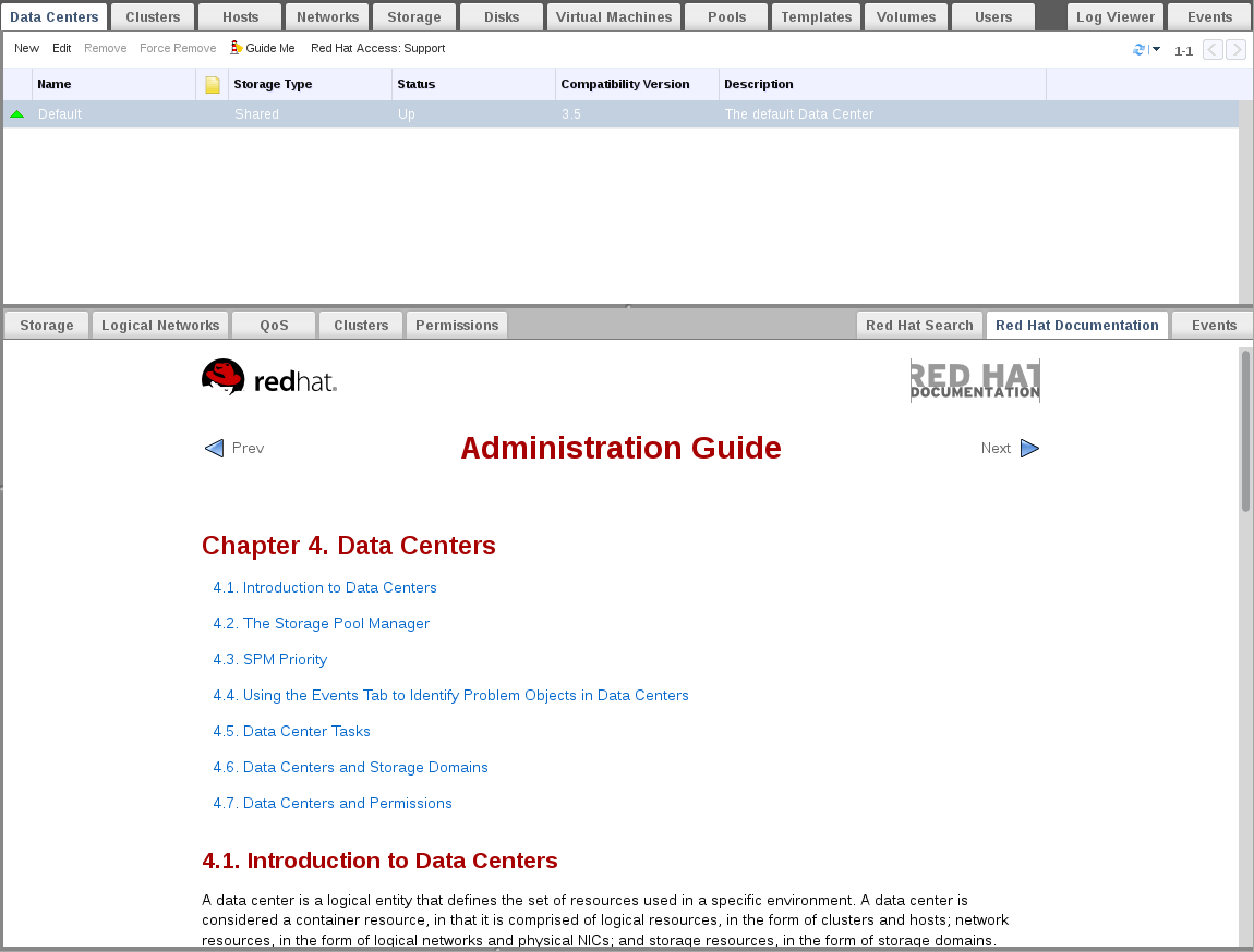
Figure C.6. Red Hat Support Plug-in - Accessing Documentation
Appendix D. Red Hat Virtualization and SSL
D.1. Replacing the Red Hat Virtualization Manager SSL/TLS Certificate
Warning
/etc/pki directory or any subdirectories. The permission for the /etc/pki and the /etc/pki/ovirt-engine directory must remain as the default 755.
Note
Prerequisites
- A third-party CA certificate. This is the certificate of the CA (Certificate Authority) that issued the certificate you want to use. It is provided as a PEM file. The certificate chain must be complete up to the root certificate. The chain's order is critical and must be from the last intermediate certificate to the root certificate. This procedure assumes that the third-party CA certificate is provided in
/tmp/3rd-party-ca-cert.pem. - The private key that you want to use for Apache httpd. It must not have a password. This procedure assumes that it is located in
/tmp/apache.key. - The certificate issued by the CA. This procedure assumes that it is located in
/tmp/apache.cer.
Procedure D.1. Extracting the Certificate and Private Key from a P12 Bundle
/etc/pki/ovirt-engine/keys/apache.p12. Red Hat recommends storing your new file in the same location. The following procedure assumes that the new P12 file is in /tmp/apache.p12.
- Back up the current
apache.p12file:# cp -p /etc/pki/ovirt-engine/keys/apache.p12 /etc/pki/ovirt-engine/keys/apache.p12.bck
- Replace the current file with the new file:
# cp /tmp/apache.p12 /etc/pki/ovirt-engine/keys/apache.p12
- Extract the private key and certificate to the required locations. If the file is password protected, you must add
-passin pass:password, replacing password with the required password.# openssl pkcs12 -in /etc/pki/ovirt-engine/keys/apache.p12 -nocerts -nodes > /tmp/apache.key # openssl pkcs12 -in /etc/pki/ovirt-engine/keys/apache.p12 -nokeys > /tmp/apache.cer
Important
Procedure D.2. Replacing the Red Hat Virtualization Manager Apache SSL Certificate
- Add your CA certificate to the host-wide trust store:
# cp /tmp/3rd-party-ca-cert.pem /etc/pki/ca-trust/source/anchors
# update-ca-trust
- The Manager has been configured to use
/etc/pki/ovirt-engine/apache-ca.pem, which is symbolically linked to/etc/pki/ovirt-engine/ca.pem. Remove the symbolic link:# rm /etc/pki/ovirt-engine/apache-ca.pem
- Save your CA certificate as
/etc/pki/ovirt-engine/apache-ca.pem:# cp /tmp/3rd-party-ca-cert.pem /etc/pki/ovirt-engine/apache-ca.pem
- Back up the existing private key and certificate:
# cp /etc/pki/ovirt-engine/keys/apache.key.nopass /etc/pki/ovirt-engine/keys/apache.key.nopass.bck
# cp /etc/pki/ovirt-engine/certs/apache.cer /etc/pki/ovirt-engine/certs/apache.cer.bck
- Copy the private key to the required location:
# cp /tmp/apache.key /etc/pki/ovirt-engine/keys/apache.key.nopass
- Copy the certificate to the required location:
# cp /tmp/apache.cer /etc/pki/ovirt-engine/certs/apache.cer
- Restart the Apache server:
# systemctl restart httpd.service
- Create a new trust store configuration file:
# vi /etc/ovirt-engine/engine.conf.d/99-custom-truststore.conf
Add the following content and save the file:ENGINE_HTTPS_PKI_TRUST_STORE="/etc/pki/java/cacerts" ENGINE_HTTPS_PKI_TRUST_STORE_PASSWORD=""
- Edit the
/etc/ovirt-engine/ovirt-websocket-proxy.conf.d/10-setup.conffile:# vi /etc/ovirt-engine/ovirt-websocket-proxy.conf.d/10-setup.conf
Make the following changes and save the file:SSL_CERTIFICATE=/etc/pki/ovirt-engine/apache-ca.pem SSL_KEY=/etc/pki/ovirt-engine/keys/apache.key.nopass
- Restart the
ovirt-engineservice:# systemctl restart ovirt-engine.service
- Replacing the certificate can cause the log collector to fail. To prevent this, create a new log collector configuration file:
# vi /etc/ovirt-engine/logcollector.conf.d/99-custom-ca-cert.conf
Add the following content and save the file:[LogCollector] cert-file=/etc/pki/ovirt-engine/apache-ca.pem
D.2. Setting Up SSL or TLS Connections between the Manager and an LDAP Server
Note
X.509 CERTIFICATE TRUST STORE section of the README file at /usr/share/doc/ovirt-engine-extension-aaa-ldap-version.
Procedure D.3. Creating a PEM-encoded CA certificate
- On the Red Hat Virtualization Manager, copy the root CA certificate of the LDAP server to the
/tmpdirectory and import the root CA certificate usingkeytoolto create a PEM-encoded CA certificate. The following command imports the root CA certificate at /tmp/myrootca.pem and creates a PEM-encoded CA certificate myrootca.jks under /etc/ovirt-engine/aaa/. Note down the certificate's location and password. If you are using the interactive setup tool, this is all the information you need. If you are configuring the LDAP server manually, follow the rest of the procedure to update the configuration files.$ keytool -importcert -noprompt -trustcacerts -alias myrootca -file /tmp/myrootca.pem -keystore /etc/ovirt-engine/aaa/myrootca.jks -storepass password
- Update the
/etc/ovirt-engine/aaa/profile1.propertiesfile with the certificate information:Note
${local:_basedir}is the directory where the LDAP property configuration file resides and points to the/etc/ovirt-engine/aaadirectory. If you created the PEM-encoded CA certificate in a different directory, replace${local:_basedir}with the full path to the certificate.- To use startTLS (recommended):
# Create keystore, import certificate chain and uncomment pool.default.ssl.startTLS = true pool.default.ssl.truststore.file = ${local:_basedir}/myrootca.jks pool.default.ssl.truststore.password = password - To use SSL:
# Create keystore, import certificate chain and uncomment
pool.default.serverset.single.port = 636
pool.default.ssl.enable = true
pool.default.ssl.truststore.file = ${local:_basedir}/myrootca.jks
pool.default.ssl.truststore.password = password
Appendix E. Using Search, Bookmarks, and Tags
E.1. Searches
E.1.1. Performing Searches in Red Hat Virtualization
E.1.2. Search Syntax and Examples
result type: {criteria} [sortby sort_spec]
The following examples describe how the search query is used and help you to understand how Red Hat Virtualization assists with building search queries.
| Example | Result |
|---|---|
| Hosts: Vms.status = up | Displays a list of all hosts running virtual machines that are up. |
| Vms: domain = qa.company.com | Displays a list of all virtual machines running on the specified domain. |
| Vms: users.name = Mary | Displays a list of all virtual machines belonging to users with the user name Mary. |
| Events: severity > normal sortby time | Displays the list of all Events whose severity is higher than Normal, sorted by time. |
E.1.3. Search Auto-Completion
Hosts: Vms.status = down
| Input | List Items Displayed | Action |
|---|---|---|
h | Hosts (1 option only) |
Select
Hosts or;
Type
Hosts
|
Hosts: |
All host properties
| Type v |
Hosts: v | host properties starting with a v | Select Vms or type Vms |
Hosts: Vms | All virtual machine properties | Type s |
Hosts: Vms.s | All virtual machine properties beginning with s | Select status or type status |
Hosts: Vms.status | =
=!
| Select or type = |
Hosts: Vms.status = | All status values | Select or type down |
E.1.4. Search Result Type Options
- Vms for a list of virtual machines
- Host for a list of hosts
- Pools for a list of pools
- Template for a list of templates
- Event for a list of events
- Users for a list of users
- Cluster for a list of clusters
- Datacenter for a list of data centers
- Storage for a list of storage domains
E.1.5. Search Criteria
{criteria} is as follows:
<prop><operator><value>
<obj-type><prop><operator><value>
The following table describes the parts of the syntax:
| Part | Description | Values | Example | Note |
|---|---|---|---|---|
| prop | The property of the searched-for resource. Can also be the property of a resource type (see obj-type), or tag (custom tag). | Limit your search to objects with a certain property. For example, search for objects with a status property. | Status | N/A |
| obj-type | A resource type that can be associated with the searched-for resource. | These are system objects, like data centers and virtual machines. | Users | N/A |
| operator | Comparison operators. |
=
!= (not equal)
>
<
>=
<=
| N/A | Value options depend on obj-type. |
| Value | What the expression is being compared to. |
String
Integer
Ranking
Date (formatted according to Regional Settings)
|
Jones
256
normal
|
|
E.1.6. Search: Multiple Criteria and Wildcards
<value> part of the syntax for strings. For example, to find all users beginning with m, enter m*.
AND and OR. For example:
Vms: users.name = m* AND status = Up
Vms: users.name = m* AND tag = "paris-loc"
AND or OR, AND is implied. AND precedes OR, and OR precedes implied AND.
E.1.7. Search: Determining Search Order
sortby. Sort direction (asc for ascending, desc for descending) can be included.
events: severity > normal sortby time desc
E.1.8. Searching for Data Centers
| Property (of resource or resource-type) | Type | Description (Reference) |
|---|---|---|
| Clusters.clusters-prop | Depends on property type | The property of the clusters associated with the data center. |
| name | String | The name of the data center. |
| description | String | A description of the data center. |
| type | String | The type of data center. |
| status | List | The availability of the data center. |
| sortby | List | Sorts the returned results by one of the resource properties. |
| page | Integer | The page number of results to display. |
Datacenter: type = nfs and status != up
- A storage type of NFS and status other than up
E.1.9. Searching for Clusters
| Property (of resource or resource-type) | Type | Description (Reference) |
|---|---|---|
| Datacenter.datacenter-prop | Depends on property type | The property of the data center associated with the cluster. |
| Datacenter | String | The data center to which the cluster belongs. |
| name | String | The unique name that identifies the clusters on the network. |
| description | String | The description of the cluster. |
| initialized | String | True or False indicating the status of the cluster. |
| sortby | List | Sorts the returned results by one of the resource properties. |
| page | Integer | The page number of results to display. |
Clusters: initialized = true or name = Default
- initialized; or
- named Default
E.1.10. Searching for Hosts
| Property (of resource or resource-type) | Type | Description (Reference) |
|---|---|---|
| Vms.Vms-prop | Depends on property type | The property of the virtual machines associated with the host. |
| Templates.templates-prop | Depends on property type | The property of the templates associated with the host. |
| Events.events-prop | Depends on property type | The property of the events associated with the host. |
| Users.users-prop | Depends on property type | The property of the users associated with the host. |
| name | String | The name of the host. |
| status | List | The availability of the host. |
| external_status | String | The health status of the host as reported by external systems and plug-ins. |
| cluster | String | The cluster to which the host belongs. |
| address | String | The unique name that identifies the host on the network. |
| cpu_usage | Integer | The percent of processing power used. |
| mem_usage | Integer | The percentage of memory used. |
| network_usage | Integer | The percentage of network usage. |
| load | Integer | Jobs waiting to be executed in the run-queue per processor, in a given time slice. |
| version | Integer | The version number of the operating system. |
| cpus | Integer | The number of CPUs on the host. |
| memory | Integer | The amount of memory available. |
| cpu_speed | Integer | The processing speed of the CPU. |
| cpu_model | String | The type of CPU. |
| active_vms | Integer | The number of virtual machines currently running. |
| migrating_vms | Integer | The number of virtual machines currently being migrated. |
| committed_mem | Integer | The percentage of committed memory. |
| tag | String | The tag assigned to the host. |
| type | String | The type of host. |
| datacenter | String | The data center to which the host belongs. |
| sortby | List | Sorts the returned results by one of the resource properties. |
| page | Integer | The page number of results to display. |
Hosts: cluster = Default and Vms.os = rhel6
- Are part of the Default cluster and host virtual machines running the Red Hat Enterprise Linux 6 operating system.
E.1.11. Searching for Networks
| Property (of resource or resource-type) | Type | Description (Reference) |
|---|---|---|
| Cluster_network.clusternetwork-prop | Depends on property type | The property of the cluster associated with the network. |
| Host_Network.hostnetwork-prop | Depends on property type | The property of the host associated with the network. |
| name | String | The human readable name that identifies the network. |
| description | String | Keywords or text describing the network, optionally used when creating the network. |
| vlanid | Integer | The VLAN ID of the network. |
| stp | String | Whether Spanning Tree Protocol (STP) is enabled or disabled for the network. |
| mtu | Integer | The maximum transmission unit for the logical network. |
| vmnetwork | String | Whether the network is only used for virtual machine traffic. |
| datacenter | String | The data center to which the network is attached. |
| sortby | List | Sorts the returned results by one of the resource properties. |
| page | Integer | The page number of results to display. |
Network: mtu > 1500 and vmnetwork = true
- with a maximum transmission unit greater than 1500 bytes
- which are set up for use by only virtual machines.
E.1.12. Searching for Storage
| Property (of resource or resource-type) | Type | Description (Reference) |
|---|---|---|
| Hosts.hosts-prop | Depends on property type | The property of the hosts associated with the storage. |
| Clusters.clusters-prop | Depends on property type | The property of the clusters associated with the storage. |
| name | String | The unique name that identifies the storage on the network. |
| status | String | The status of the storage domain. |
| external_status | String | The health status of the storage domain as reported by external systems and plug-ins. |
| datacenter | String | The data center to which the storage belongs. |
| type | String | The type of the storage. |
| size | Integer | The size of the storage. |
| used | Integer | The amount of the storage that is used. |
| committed | Integer | The amount of the storage that is committed. |
| sortby | List | Sorts the returned results by one of the resource properties. |
| page | Integer | The page number of results to display. |
Storage: size > 200 or used < 50
- total storage space greater than 200 GB; or
- used storage space less than 50 GB.
E.1.13. Searching for Disks
| Property (of resource or resource-type) | Type | Description (Reference) |
|---|---|---|
| Datacenters.datacenters-prop | Depends on property type | The property of the data centers associated with the disk. |
| Storages.storages-prop | Depends on property type | The property of the storage associated with the disk. |
| alias | String | The human readable name that identifies the storage on the network. |
| description | String | Keywords or text describing the disk, optionally used when creating the disk. |
| provisioned_size | Integer | The virtual size of the disk. |
| size | Integer | The size of the disk. |
| actual_size | Integer | The actual size allocated to the disk. |
| creation_date | Integer | The date the disk was created. |
| bootable | String | Whether the disk can or cannot be booted. Valid values are one of 0, 1, yes, or no |
| shareable | String | Whether the disk can or cannot be attached to more than one virtual machine at a time. Valid values are one of 0, 1, yes, or no |
| format | String | The format of the disk. Can be one of unused, unassigned, cow, or raw. |
| status | String | The status of the disk. Can be one of unassigned, ok, locked, invalid, or illegal. |
| disk_type | String | The type of the disk. Can be one of image or lun. |
| number_of_vms | Integer | The number of virtual machine(s) to which the disk is attached. |
| vm_names | String | The name(s) of the virtual machine(s) to which the disk is attached. |
| quota | String | The name of the quota enforced on the virtual disk. |
| sortby | List | Sorts the returned results by one of the resource properties. |
| page | Integer | The page number of results to display. |
Disks: format = cow and provisioned_size > 8
- QCOW, also known as thin provisioning, format; and
- an allocated disk size greater than 8 GB.
E.1.14. Searching for Volumes
| Property (of resource or resource-type) | Type | Description (Reference) |
|---|---|---|
| Volume.cluster-prop | Depends on property type | The property of the clusters associated with the volume. |
| Cluster | String | The name of the cluster associated with the volume. |
| name | String | The human readable name that identifies the volume. |
| type | String | Can be one of distribute, replicate, distributed_replicate, stripe, or distributed_stripe. |
| transport_type | Integer | Can be one of TCP or RDMA. |
| replica_count | Integer | Number of replica. |
| stripe_count | Integer | Number of stripes. |
| status | String | The status of the volume. Can be one of Up or Down. |
| sortby | List | Sorts the returned results by one of the resource properties. |
| page | Integer | The page number of results to display. |
Volume: transport_type = rdma and stripe_count >= 2
- Transport type set to RDMA; and
- with 2 or more stripes.
E.1.15. Searching for Virtual Machines
| Property (of resource or resource-type) | Type | Description (Reference) |
|---|---|---|
| Hosts.hosts-prop | Depends on property type | The property of the hosts associated with the virtual machine. |
| Templates.templates-prop | Depends on property type | The property of the templates associated with the virtual machine. |
| Events.events-prop | Depends on property type | The property of the events associated with the virtual machine. |
| Users.users-prop | Depends on property type | The property of the users associated with the virtual machine. |
| Storage.storage-prop | Depends on the property type | The property of storage devices associated with the virtual machine. |
| Vnic.mac-prop | Depends on the property type | The property of the MAC address associated with the virtual machine. |
| name | String | The name of the virtual machine. |
| status | List | The availability of the virtual machine. |
| ip | Integer | The IP address of the virtual machine. |
| uptime | Integer | The number of minutes that the virtual machine has been running. |
| domain | String | The domain (usually Active Directory domain) that groups these machines. |
| os | String | The operating system selected when the virtual machine was created. |
| creationdate | Date | The date on which the virtual machine was created. |
| address | String | The unique name that identifies the virtual machine on the network. |
| cpu_usage | Integer | The percent of processing power used. |
| mem_usage | Integer | The percentage of memory used. |
| network_usage | Integer | The percentage of network used. |
| memory | Integer | The maximum memory defined. |
| apps | String | The applications currently installed on the virtual machine. |
| cluster | List | The cluster to which the virtual machine belongs. |
| pool | List | The virtual machine pool to which the virtual machine belongs. |
| loggedinuser | String | The name of the user currently logged in to the virtual machine. |
| tag | List | The tags to which the virtual machine belongs. |
| datacenter | String | The data center to which the virtual machine belongs. |
| type | List | The virtual machine type (server or desktop). |
| quota | String | The name of the quota associated with the virtual machine. |
| description | String | Keywords or text describing the virtual machine, optionally used when creating the virtual machine. |
| sortby | List | Sorts the returned results by one of the resource properties. |
| page | Integer | The page number of results to display. |
| next_run_configuration_exists | Boolean | The virtual machine has pending configuration changes. |
Vms: template.name = Win* and user.name = ""
- The template on which the virtual machine is based begins with Win and the virtual machine is assigned to any user.
Vms: cluster = Default and os = windows7
- The cluster to which the virtual machine belongs is named Default and the virtual machine is running the Windows 7 operating system.
E.1.16. Searching for Pools
| Property (of resource or resource-type) | Type | Description (Reference) |
|---|---|---|
| name | String | The name of the pool. |
| description | String | The description of the pool. |
| type | List | The type of pool. |
| sortby | List | Sorts the returned results by one of the resource properties. |
| page | Integer | The page number of results to display. |
Pools: type = automatic
- Type of automatic
E.1.17. Searching for Templates
| Property (of resource or resource-type) | Type | Description (Reference) |
|---|---|---|
| Vms.Vms-prop | String | The property of the virtual machines associated with the template. |
| Hosts.hosts-prop | String | The property of the hosts associated with the template. |
| Events.events-prop | String | The property of the events associated with the template. |
| Users.users-prop | String | The property of the users associated with the template. |
| name | String | The name of the template. |
| domain | String | The domain of the template. |
| os | String | The type of operating system. |
| creationdate | Integer |
The date on which the template was created.
Date format is mm/dd/yy.
|
| childcount | Integer | The number of virtual machines created from the template. |
| mem | Integer | Defined memory. |
| description | String | The description of the template. |
| status | String | The status of the template. |
| cluster | String | The cluster associated with the template. |
| datacenter | String | The data center associated with the template. |
| quota | String | The quota associated with the template. |
| sortby | List | Sorts the returned results by one of the resource properties. |
| page | Integer | The page number of results to display. |
Template: Events.severity >= normal and Vms.uptime > 0
- Events of normal or greater severity have occurred on virtual machines derived from the template, and the virtual machines are still running.
E.1.18. Searching for Users
| Property (of resource or resource-type) | Type | Description (Reference) |
|---|---|---|
| Vms.Vms-prop | Depends on property type | The property of the virtual machines associated with the user. |
| Hosts.hosts-prop | Depends on property type | The property of the hosts associated with the user. |
| Templates.templates-prop | Depends on property type | The property of the templates associated with the user. |
| Events.events-prop | Depends on property type | The property of the events associated with the user. |
| name | String | The name of the user. |
| lastname | String | The last name of the user. |
| usrname | String | The unique name of the user. |
| department | String | The department to which the user belongs. |
| group | String | The group to which the user belongs. |
| title | String | The title of the user. |
| status | String | The status of the user. |
| role | String | The role of the user. |
| tag | String | The tag to which the user belongs. |
| pool | String | The pool to which the user belongs. |
| sortby | List | Sorts the returned results by one of the resource properties. |
| page | Integer | The page number of results to display. |
Users: Events.severity > normal and Vms.status = up or Vms.status = pause
- Events of greater than normal severity have occurred on their virtual machines AND the virtual machines are still running; or
- The users' virtual machines are paused.
E.1.19. Searching for Events
| Property (of resource or resource-type) | Type | Description (Reference) |
|---|---|---|
| Vms.Vms-prop | Depends on property type | The property of the virtual machines associated with the event. |
| Hosts.hosts-prop | Depends on property type | The property of the hosts associated with the event. |
| Templates.templates-prop | Depends on property type | The property of the templates associated with the event. |
| Users.users-prop | Depends on property type | The property of the users associated with the event. |
| Clusters.clusters-prop | Depends on property type | The property of the clusters associated with the event. |
| Volumes.Volumes-prop | Depends on property type | The property of the volumes associated with the event. |
| type | List | Type of the event. |
| severity | List | The severity of the event: Warning/Error/Normal. |
| message | String | Description of the event type. |
| time | List | Day the event occurred. |
| usrname | String | The user name associated with the event. |
| event_host | String | The host associated with the event. |
| event_vm | String | The virtual machine associated with the event. |
| event_template | String | The template associated with the event. |
| event_storage | String | The storage associated with the event. |
| event_datacenter | String | The data center associated with the event. |
| event_volume | String | The volume associated with the event. |
| correlation_id | Integer | The identification number of the event. |
| sortby | List | Sorts the returned results by one of the resource properties. |
| page | Integer | The page number of results to display. |
Events: Vms.name = testdesktop and Hosts.name = gonzo.example.com
- The event occurred on the virtual machine named
testdesktopwhile it was running on the hostgonzo.example.com.
E.2. Bookmarks
E.2.1. Saving a Query String as a Bookmark
Procedure E.1. Saving a Query String as a Bookmark
- Enter the desired search query in the search bar and perform the search.
- Click the star-shaped button to the right of the search bar to open the New Bookmark window.

Figure E.1. Bookmark Icon
- Enter the Name of the bookmark.
- Edit the Search string field (if applicable).
- Click to save the query as a bookmark and close the window.
- The search query is saved and displays in the Bookmarks pane.
E.2.2. Editing a Bookmark
Procedure E.2. Editing a Bookmark
- Click the Bookmarks tab on the far left side of the screen.
- Select the bookmark you wish to edit.
- Click the button to open the Edit Bookmark window.
- Change the Name and Search string fields as necessary.
- Click to save the edited bookmark.
E.2.3. Deleting a Bookmark
Procedure E.3. Deleting a Bookmark
- Click the Bookmarks tab on the far left side of the screen.
- Select the bookmark you wish to remove.
- Click the button to open the Remove Bookmark window.
- Click to remove the selected bookmark.
E.3. Tags
E.3.1. Using Tags to Customize Interactions with Red Hat Virtualization
E.3.2. Creating a Tag
Procedure E.4. Creating a Tag
- Click the Tags tab on the left side of the screen.
- Select the node under which you wish to create the tag. For example, to create it at the highest level, click the root node.
- Click the New button to open the New Tag window.
- Enter the Name and Description of the new tag.
- Click to create the tag.
E.3.3. Modifying a Tag
Procedure E.5. Modifying a Tag
- Click the Tags tab on the left side of the screen.
- Select the tag you wish to modify.
- Click to open the Edit Tag window.
- Change the Name and Description fields as necessary.
- Click to save the edited tag.
E.3.4. Deleting a Tag
Procedure E.6. Deleting a Tag
- Click the Tags tab on the left side of the screen.
- Select the tag you wish to delete.
- Click to open the Remove Tag(s) window. The message warns you that removing the tag will also remove all descendants of the tag.
- Click to delete the selected tag.
E.3.5. Adding and Removing Tags to and from Objects
Procedure E.7. Adding and Removing Tags to and from Objects
- Click the resource tab, and select the object(s) you wish to tag or untag.
- Click the Assign Tags button to open the Assign Tags window.
- Select the check box to assign a tag to the object, or clear the check box to detach the tag from the object.
- Click .
E.3.6. Searching for Objects Using Tags
- Enter a search query using
tagas the property and the desired value or set of values as criteria for the search.The objects tagged with the specified criteria are listed in the results list.
Appendix F. Branding
F.1. Branding
F.1.1. Re-Branding the Manager
/etc/ovirt-engine/branding/ directory on the system on which the Manager is installed. The files comprise a set of cascading style sheet files that are used to style various aspects of the graphical user interface and a set of properties files that contain messages and links that are incorporated into various components of the Manager.
F.1.2. Login Screen
- The border
- The header image on the left
- The header image on the right
- The header text
common.css.
F.1.3. Administration Portal Screen
- The logo
- The left background image
- The center background image
- The right background image
- The text to the right of the logo
web_admin.css.
F.1.4. User Portal Screen
- The logo
- The center background image
- The right background image
- The border around the main grid
- The text above the Logged in user label
user_portal.css.
F.1.5. Pop-Up Windows
- The border
- The header image on the left
- The header center image (repeated)
common.css.
F.1.6. Tabs
- Active
- Inactive
common.css and user_portal.css.
F.1.7. The Welcome Page
- The page title
- The header (left, center and right)
- The error message
- The link to forward and the associated message for that link
welcome_style.css.
The template file for the Welcome Page is a regular HTML file of the name welcome_page.template that does not contain HTML, HEAD or BODY tags. This file is inserted directly into the Welcome Page itself, and acts as a container for the content that is displayed in the Welcome Page. As such, you must edit this file to add new links or change the content itself. Another feature of the template file is that it contains placeholder text such as {user_portal} that is replaced by corresponding text in the messages.properties file when the Welcome Page is processed.
F.1.8. The Page Not Found Page
- The page title
- The header (left, center and right)
- The error message
- The link to forward and the associated message for that link
welcome_style.css.
Appendix G. System Accounts
G.1. System Accounts
G.1.1. Red Hat Virtualization Manager User Accounts
- The
vdsmuser (UID36). Required for support tools that mount and access NFS storage domains. - The
ovirtuser (UID108). Owner of theovirt-engineRed Hat JBoss Enterprise Application Platform instance. - The
ovirt-vmconsoleuser (UID498). Required for the guest serial console.
G.1.2. Red Hat Virtualization Manager Groups
- The
kvmgroup (GID36). Group members include:- The
vdsmuser.
- The
ovirtgroup (GID108). Group members include:- The
ovirtuser.
- The
ovirt-vmconsolegroup (GID498). Group members include:- The
ovirt-vmconsoleuser.
G.1.3. Virtualization Host User Accounts
- The
vdsmuser (UID36). - The
qemuuser (UID107). - The
sanlockuser (UID179). - The
ovirt-vmconsoleuser (UID498).
Important
vdsm user is fixed to a UID of 36 and the kvm group is fixed to a GID of 36.
36 or GID 36 is already used by another account on the system a conflict will arise during installation of the vdsm and qemu-kvm-rhev packages.
G.1.4. Virtualization Host Groups
- The
kvmgroup (GID36). Group members include:- The
qemuuser. - The
sanlockuser.
- The
qemugroup (GID107). Group members include:- The
vdsmuser. - The
sanlockuser.
- The
ovirt-vmconsolegroup (GID498). Group members include:- The
ovirt-vmconsoleuser.
Important
vdsm user is fixed to a UID of 36 and the kvm group is fixed to a GID of 36.
36 or GID 36 is already used by another account on the system a conflict will arise during installation of the vdsm and qemu-kvm-rhev packages.