Configuring and managing networking
Managing network interfaces and advanced networking features
Abstract
- You can configure bonds, VLANs, bridges, tunnels and other network types to connect the host to the network.
- IPSec and WireGuard provide secure VPNs between hosts and networks.
- RHEL also supports advanced networking features, such as policy-based routing and Multipath TCP (MPTCP).
Providing feedback on Red Hat documentation
We appreciate your feedback on our documentation. Let us know how we can improve it.
Submitting feedback through Jira (account required)
- Log in to the Jira website.
- Click Create in the top navigation bar
- Enter a descriptive title in the Summary field.
- Enter your suggestion for improvement in the Description field. Include links to the relevant parts of the documentation.
- Click Create at the bottom of the dialogue.
Chapter 1. Implementing consistent network interface naming
The udev device manager implements consistent device naming in Red Hat Enterprise Linux. The device manager supports different naming schemes and, by default, assigns fixed names based on firmware, topology, and location information.
Without consistent device naming, the Linux kernel assigns names to network interfaces by combining a fixed prefix and an index. The index increases as the kernel initializes the network devices. For example, eth0 represents the first Ethernet device being probed on start-up. If you add another network interface controller to the system, the assignment of the kernel device names is no longer fixed because, after a reboot, the devices can initialize in a different order. In that case, the kernel can name the devices differently.
To solve this problem, udev assigns consistent device names. This has the following advantages:
- Device names are stable across reboots.
- Device names stay fixed even if you add or remove hardware.
- Defective hardware can be seamlessly replaced.
- The network naming is stateless and does not require explicit configuration files.
Generally, Red Hat does not support systems where consistent device naming is disabled. For exceptions, see the Red Hat Knowledgebase solution Is it safe to set net.ifnames=0.
1.1. How the udev device manager renames network interfaces
To implement a consistent naming scheme for network interfaces, the udev device manager processes the following rule files in the listed order:
Optional:
/usr/lib/udev/rules.d/60-net.rulesThis file exists only if you install the
initscripts-rename-devicepackage. The/usr/lib/udev/rules.d/60-net.rulesfile defines that the deprecated/usr/lib/udev/rename_devicehelper utility searches for theHWADDRparameter in/etc/sysconfig/network-scripts/ifcfg-*files. If the value set in the variable matches the MAC address of an interface, the helper utility renames the interface to the name set in theDEVICEparameter of theifcfgfile.If the system uses only NetworkManager connection profiles in keyfile format,
udevskips this step.Only on Dell systems:
/usr/lib/udev/rules.d/71-biosdevname.rulesThis file exists only if the
biosdevnamepackage is installed, and the rules file defines that thebiosdevnameutility renames the interface according to its naming policy, if it was not renamed in the previous step.NoteInstall and use
biosdevnameonly on Dell systems./usr/lib/udev/rules.d/75-net-description.rulesThis file defines how
udevexamines the network interface and sets the properties inudev-internal variables. These variables are then processed in the next step by the/usr/lib/udev/rules.d/80-net-setup-link.rulesfile. Some of the properties can be undefined./usr/lib/udev/rules.d/80-net-setup-link.rulesThis file calls the
net_setup_linkbuiltin of theudevservice, andudevrenames the interface based on the order of the policies in theNamePolicyparameter in the/usr/lib/systemd/network/99-default.linkfile. For further details, see Network interface naming policies.If none of the policies applies,
udevdoes not rename the interface.
Additional resources
- Why are systemd network interface names different between major RHEL versions (Red Hat Knowledgebase)
1.2. Network interface naming policies
By default, the udev device manager uses the /usr/lib/systemd/network/99-default.link file to determine which device naming policies to apply when it renames interfaces. The NamePolicy parameter in this file defines which policies udev uses and in which order:
NamePolicy=keep kernel database onboard slot path
The following table describes the different actions of udev based on which policy matches first as specified by the NamePolicy parameter:
| Policy | Description | Example name |
|---|---|---|
| keep |
If the device already has a name that was assigned in the user space, | |
| kernel |
If the kernel indicates that a device name is predictable, |
|
| database |
This policy assigns names based on mappings in the |
|
| onboard | Device names incorporate firmware or BIOS-provided index numbers for onboard devices. |
|
| slot | Device names incorporate firmware or BIOS-provided PCI Express (PCIe) hot-plug slot-index numbers. |
|
| path | Device names incorporate the physical location of the connector of the hardware. |
|
| mac | Device names incorporate the MAC address. By default, Red Hat Enterprise Linux does not use this policy, but administrators can enable it. |
|
Additional resources
- How the udev device manager renames network interfaces
-
systemd.link(5)man page on your system
1.3. Network interface naming schemes
The udev device manager uses certain stable interface attributes that device drivers provide to generate consistent device names.
If a new udev version changes how the service creates names for certain interfaces, Red Hat adds a new scheme version and documents the details in the systemd.net-naming-scheme(7) man page on your system. By default, Red Hat Enterprise Linux (RHEL) 9 uses the rhel-9.0 naming scheme, even if you install or update to a later minor version of RHEL.
To prevent new drivers from providing more or other attributes for a network interface, the rhel-net-naming-sysattrs package provides the /usr/lib/udev/hwdb.d/50-net-naming-sysattr-allowlist.hwdb database. This database defines which sysfs values the udev service can use to create network interface names. The entries in the database are also versioned and influenced by the scheme version.
On RHEL 9.4 and later, you can also use all rhel-8.* naming schemes.
If you want to use a scheme other than the default, you can switch the network interface naming scheme.
For further details about the naming schemes for different device types and platforms, see the systemd.net-naming-scheme(7) man page on your system.
1.4. Switching to a different network interface naming scheme
By default, Red Hat Enterprise Linux (RHEL) 9 uses the rhel-9.0 naming scheme, even if you install or update to a later minor version of RHEL. While the default naming scheme fits in most scenarios, there might be reasons to switch to a different scheme version, for example:
- A new scheme can help to better identify a device if it adds additional attributes, such as a slot number, to an interface name.
-
An new scheme can prevent
udevfrom falling back to the kernel-assigned device names (eth*). This happens if the driver does not provide enough unique attributes for two or more interfaces to generate unique names for them.
Prerequisites
- You have access to the console of the server.
Procedure
List the network interfaces:
# ip link show
2: eno1: <BROADCAST,MULTICAST,UP,LOWER_UP> mtu 1500 qdisc fq_codel state UP mode DEFAULT group default qlen 1000
    link/ether 00:00:5e:00:53:1a brd ff:ff:ff:ff:ff:ff
...
Record the MAC addresses of the interfaces.
Optional: Display the
ID_NET_NAMING_SCHEMEproperty of a network interface to identify the naming scheme that RHEL currently uses:# udevadm info --query=property --property=ID_NET_NAMING_SCHEME /sys/class/net/eno1' ID_NET_NAMING_SCHEME=rhel-9.0Note that the property is not available on the
loloopback device.Append the
net.naming-scheme=<scheme>option to the command line of all installed kernels, for example:# grubby --update-kernel=ALL --args=net.naming-scheme=rhel-9.4Reboot the system.
# rebootBased on the MAC addresses you recorded, identify the new names of network interfaces that have changed due to the different naming scheme:
# ip link show
2: eno1np0: <BROADCAST,MULTICAST,UP,LOWER_UP> mtu 1500 qdisc fq_codel state UP mode DEFAULT group default qlen 1000
    link/ether 00:00:5e:00:53:1a brd ff:ff:ff:ff:ff:ff
...
After switching the scheme,
udevnames in this example the device with MAC address00:00:5e:00:53:1aeno1np0, whereas it was namedeno1before.Identify which NetworkManager connection profile uses an interface with the previous name:
# nmcli -f device,name connection show
DEVICE  NAME
eno1  example_profile
...
Set the
connection.interface-nameproperty in the connection profile to the new interface name:# nmcli connection modify example_profile connection.interface-name "eno1np0"Reactivate the connection profile:
# nmcli connection up example_profile
Verification
Identify the naming scheme that RHEL now uses by displaying the
ID_NET_NAMING_SCHEMEproperty of a network interface:# udevadm info --query=property --property=ID_NET_NAMING_SCHEME /sys/class/net/eno1np0' ID_NET_NAMING_SCHEME=_rhel-9.4
Additional resources
1.5. Customizing the prefix for Ethernet interfaces during installation
If you do not want to use the default device-naming policy for Ethernet interfaces, you can set a custom device prefix during the Red Hat Enterprise Linux (RHEL) installation.
Red Hat supports systems with customized Ethernet prefixes only if you set the prefix during the RHEL installation. Using the prefixdevname utility on already deployed systems is not supported.
If you set a device prefix during the installation, the udev service uses the <prefix><index> format for Ethernet interfaces after the installation. For example, if you set the prefix net, the service assigns the names net0, net1, and so on to the Ethernet interfaces.
The udev service appends the index to the custom prefix, and preserves the index values of known Ethernet interfaces. If you add an interface, udev assigns an index value that is one greater than the previously-assigned index value to the new interface.
Prerequisites
- The prefix consists of ASCII characters.
- The prefix is an alphanumeric string.
- The prefix is shorter than 16 characters.
-
The prefix does not conflict with any other well-known network interface prefix, such as
eth,eno,ens, andem.
Procedure
- Boot the Red Hat Enterprise Linux installation media.
In the boot manager, follow these steps:
-
Select the
Install Red Hat Enterprise Linux <version>entry. - Press Tab to edit the entry.
-
Append
net.ifnames.prefix=<prefix>to the kernel options. - Press Enter to start the installation program.
-
Select the
- Install Red Hat Enterprise Linux.
Verification
To verify the interface names, display the network interfaces:
# ip link show
...
2: net0: <BROADCAST,MULTICAST,UP,LOWER_UP> mtu 1500 qdisc fq_codel state UP mode DEFAULT group default qlen 1000
    link/ether 00:00:5e:00:53:1a brd ff:ff:ff:ff:ff:ff
...
Additional resources
1.6. Configuring user-defined network interface names by using udev rules
You can use udev rules to implement custom network interface names that reflect your organization’s requirements.
Procedure
Identify the network interface that you want to rename:
# ip link show
...
enp1s0: <BROADCAST,MULTICAST,UP,LOWER_UP> mtu 1500 qdisc fq_codel state UP mode DEFAULT group default qlen 1000
    link/ether 00:00:5e:00:53:1a brd ff:ff:ff:ff:ff:ff
...
Record the MAC address of the interface.
Display the device type ID of the interface:
# cat /sys/class/net/enp1s0/type
1
Create the
/etc/udev/rules.d/70-persistent-net.rulesfile, and add a rule for each interface that you want to rename:SUBSYSTEM=="net",ACTION=="add",ATTR{address}=="<MAC_address>",ATTR{type}=="<device_type_id>",NAME="<new_interface_name>"ImportantUse only
70-persistent-net.rulesas a file name if you require consistent device names during the boot process. Thedracututility adds a file with this name to theinitrdimage if you regenerate the RAM disk image.For example, use the following rule to rename the interface with MAC address
00:00:5e:00:53:1atoprovider0:SUBSYSTEM=="net",ACTION=="add",ATTR{address}=="00:00:5e:00:53:1a",ATTR{type}=="1",NAME="provider0"Optional: Regenerate the
initrdRAM disk image:# dracut -fYou require this step only if you need networking capabilities in the RAM disk. For example, this is the case if the root file system is stored on a network device, such as iSCSI.
Identify which NetworkManager connection profile uses the interface that you want to rename:
# nmcli -f device,name connection show
DEVICE  NAME
enp1s0  example_profile
...
Unset the
connection.interface-nameproperty in the connection profile:# nmcli connection modify example_profile connection.interface-name ""Temporarily, configure the connection profile to match both the new and the previous interface name:
# nmcli connection modify example_profile match.interface-name "provider0 enp1s0"Reboot the system:
# rebootVerify that the device with the MAC address that you specified in the link file has been renamed to
provider0:# ip link show provider0: <BROADCAST,MULTICAST,UP,LOWER_UP> mtu 1500 qdisc mq state UP mode DEFAULT group default qlen 1000 link/ether 00:00:5e:00:53:1a brd ff:ff:ff:ff:ff:ff ...Configure the connection profile to match only the new interface name:
# nmcli connection modify example_profile match.interface-name "provider0"You have now removed the old interface name from the connection profile.
Reactivate the connection profile:
# nmcli connection up example_profile
Additional resources
-
udev(7)man page on your system
1.7. Configuring user-defined network interface names by using systemd link files
You can use systemd link files to implement custom network interface names that reflect your organization’s requirements.
Prerequisites
- You must meet one of these conditions: NetworkManager does not manage this interface, or the corresponding connection profile uses the keyfile format.
Procedure
Identify the network interface that you want to rename:
# ip link show
...
enp1s0: <BROADCAST,MULTICAST,UP,LOWER_UP> mtu 1500 qdisc fq_codel state UP mode DEFAULT group default qlen 1000
    link/ether 00:00:5e:00:53:1a brd ff:ff:ff:ff:ff:ff
...
Record the MAC address of the interface.
If it does not already exist, create the
/etc/systemd/network/directory:# mkdir -p /etc/systemd/network/For each interface that you want to rename, create a
70-*.linkfile in the/etc/systemd/network/directory with the following content:[Match] MACAddress=<MAC_address> [Link] Name=<new_interface_name>
ImportantUse a file name with a
70-prefix to keep the file names consistent with theudevrules-based solution.For example, create the
/etc/systemd/network/70-provider0.linkfile with the following content to rename the interface with MAC address00:00:5e:00:53:1atoprovider0:[Match] MACAddress=00:00:5e:00:53:1a [Link] Name=provider0
Optional: Regenerate the
initrdRAM disk image:# dracut -fYou require this step only if you need networking capabilities in the RAM disk. For example, this is the case if the root file system is stored on a network device, such as iSCSI.
Identify which NetworkManager connection profile uses the interface that you want to rename:
# nmcli -f device,name connection show
DEVICE  NAME
enp1s0  example_profile
...
Unset the
connection.interface-nameproperty in the connection profile:# nmcli connection modify example_profile connection.interface-name ""Temporarily, configure the connection profile to match both the new and the previous interface name:
# nmcli connection modify example_profile match.interface-name "provider0 enp1s0"Reboot the system:
# rebootVerify that the device with the MAC address that you specified in the link file has been renamed to
provider0:# ip link show provider0: <BROADCAST,MULTICAST,UP,LOWER_UP> mtu 1500 qdisc mq state UP mode DEFAULT group default qlen 1000 link/ether 00:00:5e:00:53:1a brd ff:ff:ff:ff:ff:ff ...Configure the connection profile to match only the new interface name:
# nmcli connection modify example_profile match.interface-name "provider0"You have now removed the old interface name from the connection profile.
Reactivate the connection profile.
# nmcli connection up example_profile
Additional resources
-
systemd.link(5)man page on your system
1.8. Assigning alternative names to a network interface by using systemd link files
With alternative interface naming, the kernel can assign additional names to network interfaces. You can use these alternative names in the same way as the normal interface names in commands that require a network interface name.
Prerequisites
- You must use ASCII characters for the alternative name.
- The alternative name must be shorter than 128 characters.
Procedure
Display the network interface names and their MAC addresses:
# ip link show
...
enp1s0: <BROADCAST,MULTICAST,UP,LOWER_UP> mtu 1500 qdisc fq_codel state UP mode DEFAULT group default qlen 1000
    link/ether 00:00:5e:00:53:1a brd ff:ff:ff:ff:ff:ff
...
Record the MAC address of the interface to which you want to assign an alternative name.
If it does not already exist, create the
/etc/systemd/network/directory:# mkdir -p /etc/systemd/network/For each interface that must have an alternative name, create a copy of the
/usr/lib/systemd/network/99-default.linkfile with a unique name and.linksuffix in the/etc/systemd/network/directory, for example:# cp /usr/lib/systemd/network/99-default.link /etc/systemd/network/98-lan.linkModify the file you created in the previous step. Rewrite the
[Match]section as follows, and append theAlternativeNameentries to the[Link]section:[Match] MACAddress=<MAC_address> [Link] ... AlternativeName=<alternative_interface_name_1> AlternativeName=<alternative_interface_name_2> AlternativeName=<alternative_interface_name_n>
For example, create the
/etc/systemd/network/70-altname.linkfile with the following content to assignprovideras an alternative name to the interface with MAC address00:00:5e:00:53:1a:[Match] MACAddress=00:00:5e:00:53:1a [Link] NamePolicy=keep kernel database onboard slot path AlternativeNamesPolicy=database onboard slot path MACAddressPolicy=none AlternativeName=provider
Regenerate the
initrdRAM disk image:# dracut -fReboot the system:
# reboot
Verification
Use the alternative interface name. For example, display the IP address settings of the device with the alternative name
provider:# ip address show provider 2: enp1s0: <BROADCAST,MULTICAST,UP,LOWER_UP> mtu 1500 qdisc fq_codel state UP group default qlen 1000 link/ether 00:00:5e:00:53:1a brd ff:ff:ff:ff:ff:ff altname provider ...
Additional resources
- What is AlternativeNamesPolicy in Interface naming scheme? (Red Hat Knowledgebase)
Chapter 2. Configuring an Ethernet connection
NetworkManager creates a connection profile for each Ethernet adapter that is installed in a host. By default, this profile uses DHCP for both IPv4 and IPv6 connections. Modify this automatically-created profile or add a new one in the following cases:
- The network requires custom settings, such as a static IP address configuration.
- You require multiple profiles because the host roams among different networks.
Red Hat Enterprise Linux provides administrators different options to configure Ethernet connections. For example:
-
Use
nmclito configure connections on the command line. -
Use
nmtuito configure connections in a text-based user interface. -
Use the GNOME Settings menu or
nm-connection-editorapplication to configure connections in a graphical interface. -
Use
nmstatectlto configure connections through the Nmstate API. - Use RHEL system roles to automate the configuration of connections on one or multiple hosts.
If you want to manually configure Ethernet connections on hosts running in the Microsoft Azure cloud, disable the cloud-init service or configure it to ignore the network settings retrieved from the cloud environment. Otherwise, cloud-init will override on the next reboot the network settings that you have manually configured.
2.1. Configuring an Ethernet connection by using nmcli
If you connect a host to the network over Ethernet, you can manage the connection’s settings on the command line by using the nmcli utility.
Prerequisites
- A physical or virtual Ethernet Network Interface Controller (NIC) exists in the server’s configuration.
Procedure
List the NetworkManager connection profiles:
# nmcli connection show
NAME                UUID                                  TYPE      DEVICE
Wired connection 1  a5eb6490-cc20-3668-81f8-0314a27f3f75  ethernet  enp1s0
By default, NetworkManager creates a profile for each NIC in the host. If you plan to connect this NIC only to a specific network, adapt the automatically-created profile. If you plan to connect this NIC to networks with different settings, create individual profiles for each network.
If you want to create an additional connection profile, enter:
# nmcli connection add con-name <connection-name> ifname <device-name> type ethernetSkip this step to modify an existing profile.
Optional: Rename the connection profile:
# nmcli connection modify "Wired connection 1" connection.id "Internal-LAN"On hosts with multiple profiles, a meaningful name makes it easier to identify the purpose of a profile.
Display the current settings of the connection profile:
# nmcli connection show Internal-LAN
...
connection.interface-name:     enp1s0
connection.autoconnect:        yes
ipv4.method:                   auto
ipv6.method:                   auto
...
Configure the IPv4 settings:
To use DHCP, enter:
# nmcli connection modify Internal-LAN ipv4.method autoSkip this step if
ipv4.methodis already set toauto(default).To set a static IPv4 address, network mask, default gateway, DNS servers, and search domain, enter:
# nmcli connection modify Internal-LAN ipv4.method manual ipv4.addresses 192.0.2.1/24 ipv4.gateway 192.0.2.254 ipv4.dns 192.0.2.200 ipv4.dns-search example.com
Configure the IPv6 settings:
To use stateless address autoconfiguration (SLAAC), enter:
# nmcli connection modify Internal-LAN ipv6.method autoSkip this step if
ipv6.methodis already set toauto(default).To set a static IPv6 address, network mask, default gateway, DNS servers, and search domain, enter:
# nmcli connection modify Internal-LAN ipv6.method manual ipv6.addresses 2001:db8:1::fffe/64 ipv6.gateway 2001:db8:1::fffe ipv6.dns 2001:db8:1::ffbb ipv6.dns-search example.com
To customize other settings in the profile, use the following command:
# nmcli connection modify <connection-name> <setting> <value>Enclose values with spaces or semicolons in quotes.
Activate the profile:
# nmcli connection up Internal-LAN
Verification
Display the IP settings of the NIC:
# ip address show enp1s0
2: enp1s0: <BROADCAST,MULTICAST,UP,LOWER_UP> mtu 1500 qdisc fq_codel state UP group default qlen 1000
    link/ether 52:54:00:17:b8:b6 brd ff:ff:ff:ff:ff:ff
    inet 192.0.2.1/24 brd 192.0.2.255 scope global noprefixroute enp1s0
       valid_lft forever preferred_lft forever
    inet6 2001:db8:1::fffe/64 scope global noprefixroute
       valid_lft forever preferred_lft forever
Display the IPv4 default gateway:
# ip route show default
default via 192.0.2.254 dev enp1s0 proto static metric 102
Display the IPv6 default gateway:
# ip -6 route show default
default via 2001:db8:1::ffee dev enp1s0 proto static metric 102 pref medium
Display the DNS settings:
# cat /etc/resolv.conf
search example.com
nameserver 192.0.2.200
nameserver 2001:db8:1::ffbb
If multiple connection profiles are active at the same time, the order of
nameserverentries depend on the DNS priority values in these profiles and the connection types.Use the
pingutility to verify that this host can send packets to other hosts:# ping <host-name-or-IP-address>
Troubleshooting
- Verify that the network cable is plugged-in to the host and a switch.
- Check whether the link failure exists only on this host or also on other hosts connected to the same switch.
- Verify that the network cable and the network interface are working as expected. Perform hardware diagnosis steps and replace defective cables and network interface cards.
- If the configuration on the disk does not match the configuration on the device, starting or restarting NetworkManager creates an in-memory connection that reflects the configuration of the device. For further details and how to avoid this problem, see the Red Hat Knowledgebase solution NetworkManager duplicates a connection after restart of NetworkManager service.
Additional resources
-
nm-settings(5)man page on your system
2.2. Configuring an Ethernet connection by using the nmcli interactive editor
If you connect a host to the network over Ethernet, you can manage the connection’s settings on the command line by using the nmcli utility.
Prerequisites
- A physical or virtual Ethernet Network Interface Controller (NIC) exists in the server’s configuration.
Procedure
List the NetworkManager connection profiles:
# nmcli connection show
NAME                UUID                                  TYPE      DEVICE
Wired connection 1  a5eb6490-cc20-3668-81f8-0314a27f3f75  ethernet  enp1s0
By default, NetworkManager creates a profile for each NIC in the host. If you plan to connect this NIC only to a specific network, adapt the automatically-created profile. If you plan to connect this NIC to networks with different settings, create individual profiles for each network.
Start
nmcliin interactive mode:To create an additional connection profile, enter:
# nmcli connection edit type ethernet con-name "<connection-name>"To modify an existing connection profile, enter:
# nmcli connection edit con-name "<connection-name>"
Optional: Rename the connection profile:
nmcli> set connection.id Internal-LANOn hosts with multiple profiles, a meaningful name makes it easier to identify the purpose of a profile.
Do not use quotes to set an ID that contains spaces to avoid that
nmclimakes the quotes part of the name. For example, to setExample Connectionas ID, enterset connection.id Example Connection.Display the current settings of the connection profile:
nmcli> print
...
connection.interface-name:     enp1s0
connection.autoconnect:        yes
ipv4.method:                   auto
ipv6.method:                   auto
...
If you create a new connection profile, set the network interface:
nmcli> set connection.interface-name enp1s0Configure the IPv4 settings:
To use DHCP, enter:
nmcli> set ipv4.method autoSkip this step if
ipv4.methodis already set toauto(default).To set a static IPv4 address, network mask, default gateway, DNS servers, and search domain, enter:
nmcli> ipv4.addresses 192.0.2.1/24
Do you also want to set 'ipv4.method' to 'manual'? [yes]: yes
nmcli> ipv4.gateway 192.0.2.254
nmcli> ipv4.dns 192.0.2.200
nmcli> ipv4.dns-search example.com
Configure the IPv6 settings:
To use stateless address autoconfiguration (SLAAC), enter:
nmcli> set ipv6.method autoSkip this step if
ipv6.methodis already set toauto(default).To set a static IPv6 address, network mask, default gateway, DNS servers, and search domain, enter:
nmcli> ipv6.addresses 2001:db8:1::fffe/64
Do you also want to set 'ipv6.method' to 'manual'? [yes]: yes
nmcli> ipv6.gateway 2001:db8:1::fffe
nmcli> ipv6.dns 2001:db8:1::ffbb
nmcli> ipv6.dns-search example.com
Save and activate the connection:
nmcli> save persistentLeave the interactive mode:
nmcli> quit
Verification
Display the IP settings of the NIC:
# ip address show enp1s0
2: enp1s0: <BROADCAST,MULTICAST,UP,LOWER_UP> mtu 1500 qdisc fq_codel state UP group default qlen 1000
    link/ether 52:54:00:17:b8:b6 brd ff:ff:ff:ff:ff:ff
    inet 192.0.2.1/24 brd 192.0.2.255 scope global noprefixroute enp1s0
       valid_lft forever preferred_lft forever
    inet6 2001:db8:1::fffe/64 scope global noprefixroute
       valid_lft forever preferred_lft forever
Display the IPv4 default gateway:
# ip route show default
default via 192.0.2.254 dev enp1s0 proto static metric 102
Display the IPv6 default gateway:
# ip -6 route show default
default via 2001:db8:1::ffee dev enp1s0 proto static metric 102 pref medium
Display the DNS settings:
# cat /etc/resolv.conf
search example.com
nameserver 192.0.2.200
nameserver 2001:db8:1::ffbb
If multiple connection profiles are active at the same time, the order of
nameserverentries depend on the DNS priority values in these profiles and the connection types.Use the
pingutility to verify that this host can send packets to other hosts:# ping <host-name-or-IP-address>
Troubleshooting
- Verify that the network cable is plugged-in to the host and a switch.
- Check whether the link failure exists only on this host or also on other hosts connected to the same switch.
- Verify that the network cable and the network interface are working as expected. Perform hardware diagnosis steps and replace defective cables and network interface cards.
- If the configuration on the disk does not match the configuration on the device, starting or restarting NetworkManager creates an in-memory connection that reflects the configuration of the device. For further details and how to avoid this problem, see the Red Hat Knowledgebase solution NetworkManager duplicates a connection after restart of NetworkManager service.
Additional resources
-
nm-settings(5)andnmcli(1)man pages on your system
2.3. Configuring an Ethernet connection by using nmtui
If you connect a host to the network over Ethernet, you can manage the connection’s settings in a text-based user interface by using the nmtui application. Use nmtui to create new profiles and to update existing ones on a host without a graphical interface.
In nmtui:
- Navigate by using the cursor keys.
- Press a button by selecting it and hitting Enter.
- Select and clear checkboxes by using Space.
- To return to the previous screen, use ESC.
Prerequisites
- A physical or virtual Ethernet Network Interface Controller (NIC) exists in the server’s configuration.
Procedure
If you do not know the network device name you want to use in the connection, display the available devices:
# nmcli device status
DEVICE     TYPE      STATE                   CONNECTION
enp1s0     ethernet  unavailable             --
...
Start
nmtui:# nmtui- Select Edit a connection, and press Enter.
Choose whether to add a new connection profile or to modify an existing one:
To create a new profile:
- Press Add.
- Select Ethernet from the list of network types, and press Enter.
- To modify an existing profile, select the profile from the list, and press Enter.
Optional: Update the name of the connection profile.
On hosts with multiple profiles, a meaningful name makes it easier to identify the purpose of a profile.
- If you create a new connection profile, enter the network device name into the Device field.
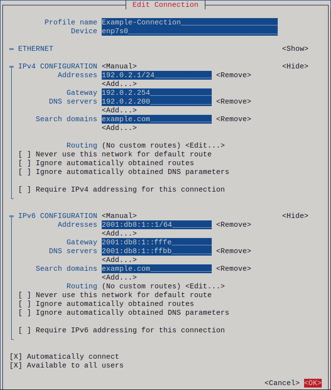
Depending on your environment, configure the IP address settings in the
IPv4 configurationandIPv6 configurationareas accordingly. For this, press the button next to these areas, and select:- Disabled, if this connection does not require an IP address.
- Automatic, if a DHCP server dynamically assigns an IP address to this NIC.
Manual, if the network requires static IP address settings. In this case, you must fill further fields:
- Press Show next to the protocol you want to configure to display additional fields.
Press Add next to Addresses, and enter the IP address and the subnet mask in Classless Inter-Domain Routing (CIDR) format.
If you do not specify a subnet mask, NetworkManager sets a
/32subnet mask for IPv4 addresses and/64for IPv6 addresses.- Enter the address of the default gateway.
- Press Add next to DNS servers, and enter the DNS server address.
- Press Add next to Search domains, and enter the DNS search domain.
Figure 2.1. Example of an Ethernet connection with static IP address settings
- Press OK to create and automatically activate the new connection.
- Press Back to return to the main menu.
-
Select Quit, and press Enter to close the
nmtuiapplication.
Verification
Display the IP settings of the NIC:
# ip address show enp1s0
2: enp1s0: <BROADCAST,MULTICAST,UP,LOWER_UP> mtu 1500 qdisc fq_codel state UP group default qlen 1000
    link/ether 52:54:00:17:b8:b6 brd ff:ff:ff:ff:ff:ff
    inet 192.0.2.1/24 brd 192.0.2.255 scope global noprefixroute enp1s0
       valid_lft forever preferred_lft forever
    inet6 2001:db8:1::fffe/64 scope global noprefixroute
       valid_lft forever preferred_lft forever
Display the IPv4 default gateway:
# ip route show default
default via 192.0.2.254 dev enp1s0 proto static metric 102
Display the IPv6 default gateway:
# ip -6 route show default
default via 2001:db8:1::ffee dev enp1s0 proto static metric 102 pref medium
Display the DNS settings:
# cat /etc/resolv.conf
search example.com
nameserver 192.0.2.200
nameserver 2001:db8:1::ffbb
If multiple connection profiles are active at the same time, the order of
nameserverentries depend on the DNS priority values in these profiles and the connection types.Use the
pingutility to verify that this host can send packets to other hosts:# ping <host-name-or-IP-address>
Troubleshooting
- Verify that the network cable is plugged-in to the host and a switch.
- Check whether the link failure exists only on this host or also on other hosts connected to the same switch.
- Verify that the network cable and the network interface are working as expected. Perform hardware diagnosis steps and replace defective cables and network interface cards.
- If the configuration on the disk does not match the configuration on the device, starting or restarting NetworkManager creates an in-memory connection that reflects the configuration of the device. For further details and how to avoid this problem, see the Red Hat Knowledgebase solution NetworkManager duplicates a connection after restart of NetworkManager service.
2.4. Configuring an Ethernet connection by using control-center
If you connect a host to the network over Ethernet, you can manage the connection’s settings with a graphical interface by using the GNOME Settings menu.
Note that control-center does not support as many configuration options as the nm-connection-editor application or the nmcli utility.
Prerequisites
- A physical or virtual Ethernet Network Interface Controller (NIC) exists in the server’s configuration.
- GNOME is installed.
Procedure
-
Press the Super key, enter
Settings, and press Enter. - Select Network in the navigation on the left.
Choose whether to add a new connection profile or to modify an existing one:
- To create a new profile, click the button next to the Ethernet entry.
- To modify an existing profile, click the gear icon next to the profile entry.
Optional: On the Identity tab, update the name of the connection profile.
On hosts with multiple profiles, a meaningful name makes it easier to identify the purpose of a profile.
Depending on your environment, configure the IP address settings on the IPv4 and IPv6 tabs accordingly:
-
To use DHCP or IPv6 stateless address autoconfiguration (SLAAC), select
Automatic (DHCP)as method (default). To set a static IP address, network mask, default gateway, DNS servers, and search domain, select
Manualas method, and fill the fields on the tabs: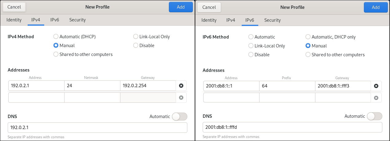
-
To use DHCP or IPv6 stateless address autoconfiguration (SLAAC), select
Depending on whether you add or modify a connection profile, click the or button to save the connection.
The GNOME
control-centerautomatically activates the connection.
Verification
Display the IP settings of the NIC:
# ip address show enp1s0
2: enp1s0: <BROADCAST,MULTICAST,UP,LOWER_UP> mtu 1500 qdisc fq_codel state UP group default qlen 1000
    link/ether 52:54:00:17:b8:b6 brd ff:ff:ff:ff:ff:ff
    inet 192.0.2.1/24 brd 192.0.2.255 scope global noprefixroute enp1s0
       valid_lft forever preferred_lft forever
    inet6 2001:db8:1::fffe/64 scope global noprefixroute
       valid_lft forever preferred_lft forever
Display the IPv4 default gateway:
# ip route show default
default via 192.0.2.254 dev enp1s0 proto static metric 102
Display the IPv6 default gateway:
# ip -6 route show default
default via 2001:db8:1::ffee dev enp1s0 proto static metric 102 pref medium
Display the DNS settings:
# cat /etc/resolv.conf
search example.com
nameserver 192.0.2.200
nameserver 2001:db8:1::ffbb
If multiple connection profiles are active at the same time, the order of
nameserverentries depend on the DNS priority values in these profiles and the connection types.Use the
pingutility to verify that this host can send packets to other hosts:# ping <host-name-or-IP-address>
Troubleshooting steps
- Verify that the network cable is plugged-in to the host and a switch.
- Check whether the link failure exists only on this host or also on other hosts connected to the same switch.
- Verify that the network cable and the network interface are working as expected. Perform hardware diagnosis steps and replace defective cables and network interface cards.
- If the configuration on the disk does not match the configuration on the device, starting or restarting NetworkManager creates an in-memory connection that reflects the configuration of the device. For further details and how to avoid this problem, see the Red Hat Knowledgebase solution NetworkManager duplicates a connection after restart of NetworkManager service.
2.5. Configuring an Ethernet connection by using nm-connection-editor
If you connect a host to the network over Ethernet, you can manage the connection’s settings with a graphical interface by using the nm-connection-editor application.
Prerequisites
- A physical or virtual Ethernet Network Interface Controller (NIC) exists in the server’s configuration.
- GNOME is installed.
Procedure
Open a terminal, and enter:
$ nm-connection-editorChoose whether to add a new connection profile or to modify an existing one:
To create a new profile:
- Click the button
- Select Ethernet as connection type, and click .
- To modify an existing profile, double-click the profile entry.
Optional: Update the name of the profile in the Connection Name field.
On hosts with multiple profiles, a meaningful name makes it easier to identify the purpose of a profile.
If you create a new profile, select the device on the
Ethernettab: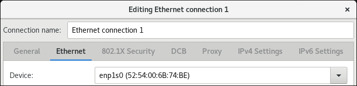
Depending on your environment, configure the IP address settings on the IPv4 Settings and IPv6 Settings tabs accordingly:
-
To use DHCP or IPv6 stateless address autoconfiguration (SLAAC), select
Automatic (DHCP)as method (default). To set a static IP address, network mask, default gateway, DNS servers, and search domain, select
Manualas method, and fill the fields on the tabs: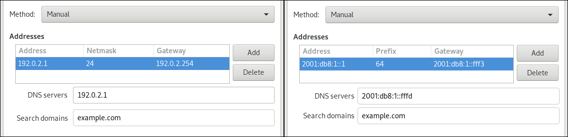
-
To use DHCP or IPv6 stateless address autoconfiguration (SLAAC), select
- Click .
- Close nm-connection-editor.
Verification
Display the IP settings of the NIC:
# ip address show enp1s0
2: enp1s0: <BROADCAST,MULTICAST,UP,LOWER_UP> mtu 1500 qdisc fq_codel state UP group default qlen 1000
    link/ether 52:54:00:17:b8:b6 brd ff:ff:ff:ff:ff:ff
    inet 192.0.2.1/24 brd 192.0.2.255 scope global noprefixroute enp1s0
       valid_lft forever preferred_lft forever
    inet6 2001:db8:1::fffe/64 scope global noprefixroute
       valid_lft forever preferred_lft forever
Display the IPv4 default gateway:
# ip route show default
default via 192.0.2.254 dev enp1s0 proto static metric 102
Display the IPv6 default gateway:
# ip -6 route show default
default via 2001:db8:1::ffee dev enp1s0 proto static metric 102 pref medium
Display the DNS settings:
# cat /etc/resolv.conf
search example.com
nameserver 192.0.2.200
nameserver 2001:db8:1::ffbb
If multiple connection profiles are active at the same time, the order of
nameserverentries depend on the DNS priority values in these profiles and the connection types.Use the
pingutility to verify that this host can send packets to other hosts:# ping <host-name-or-IP-address>
Troubleshooting steps
- Verify that the network cable is plugged-in to the host and a switch.
- Check whether the link failure exists only on this host or also on other hosts connected to the same switch.
- Verify that the network cable and the network interface are working as expected. Perform hardware diagnosis steps and replace defective cables and network interface cards.
- If the configuration on the disk does not match the configuration on the device, starting or restarting NetworkManager creates an in-memory connection that reflects the configuration of the device. For further details and how to avoid this problem, see the Red Hat Knowledgebase solution NetworkManager duplicates a connection after restart of NetworkManager service.
2.6. Configuring an Ethernet connection with a static IP address by using nmstatectl
Use the nmstatectl utility to configure an Ethernet connection through the Nmstate API. The Nmstate API ensures that, after setting the configuration, the result matches the configuration file. If anything fails, nmstatectl automatically rolls back the changes to avoid leaving the system in an incorrect state.
Prerequisites
- A physical or virtual Ethernet Network Interface Controller (NIC) exists in the server’s configuration.
-
The
nmstatepackage is installed.
Procedure
Create a YAML file, for example
~/create-ethernet-profile.yml, with the following content:--- interfaces: - name: enp1s0 type: ethernet state: up ipv4: enabled: true address: - ip: 192.0.2.1 prefix-length: 24 dhcp: false ipv6: enabled: true address: - ip: 2001:db8:1::1 prefix-length: 64 autoconf: false dhcp: false routes: config: - destination: 0.0.0.0/0 next-hop-address: 192.0.2.254 next-hop-interface: enp1s0 - destination: ::/0 next-hop-address: 2001:db8:1::fffe next-hop-interface: enp1s0 dns-resolver: config: search: - example.com server: - 192.0.2.200 - 2001:db8:1::ffbbThese settings define an Ethernet connection profile for the
enp1s0device with the following settings:-
A static IPv4 address -
192.0.2.1with the/24subnet mask -
A static IPv6 address -
2001:db8:1::1with the/64subnet mask -
An IPv4 default gateway -
192.0.2.254 -
An IPv6 default gateway -
2001:db8:1::fffe -
An IPv4 DNS server -
192.0.2.200 -
An IPv6 DNS server -
2001:db8:1::ffbb -
A DNS search domain -
example.com
-
A static IPv4 address -
Optional: You can define the
identifier: mac-addressandmac-address: <mac_address>properties in theinterfacesproperty to identify the network interface card by its MAC address instead of its name, for example:--- interfaces: - name: <profile_name> type: ethernet identifier: mac-address mac-address: <mac_address> ...
Apply the settings to the system:
# nmstatectl apply ~/create-ethernet-profile.yml
Verification
Display the current state in YAML format:
# nmstatectl show enp1s0Display the IP settings of the NIC:
# ip address show enp1s0
2: enp1s0: <BROADCAST,MULTICAST,UP,LOWER_UP> mtu 1500 qdisc fq_codel state UP group default qlen 1000
    link/ether 52:54:00:17:b8:b6 brd ff:ff:ff:ff:ff:ff
    inet 192.0.2.1/24 brd 192.0.2.255 scope global noprefixroute enp1s0
       valid_lft forever preferred_lft forever
    inet6 2001:db8:1::fffe/64 scope global noprefixroute
       valid_lft forever preferred_lft forever
Display the IPv4 default gateway:
# ip route show default
default via 192.0.2.254 dev enp1s0 proto static metric 102
Display the IPv6 default gateway:
# ip -6 route show default
default via 2001:db8:1::ffee dev enp1s0 proto static metric 102 pref medium
Display the DNS settings:
# cat /etc/resolv.conf
search example.com
nameserver 192.0.2.200
nameserver 2001:db8:1::ffbb
If multiple connection profiles are active at the same time, the order of
nameserverentries depend on the DNS priority values in these profiles and the connection types.Use the
pingutility to verify that this host can send packets to other hosts:# ping <host-name-or-IP-address>
Additional resources
-
nmstatectl(8)man page on your system -
/usr/share/doc/nmstate/examples/directory
2.7. Configuring an Ethernet connection with a static IP address by using the network RHEL system role with an interface name
To connect a Red Hat Enterprise Linux host to an Ethernet network, create a NetworkManager connection profile for the network device. By using Ansible and the network RHEL system role, you can automate this process and remotely configure connection profiles on the hosts defined in a playbook.
You can use the network RHEL system role to configure an Ethernet connection with static IP addresses, gateways, and DNS settings, and assign them to a specified interface name.
Typically, administrators want to reuse a playbook and not maintain individual playbooks for each host to which Ansible should assign static IP addresses. In this case, you can use variables in the playbook and maintain the settings in the inventory. As a result, you need only one playbook to dynamically assign individual settings to multiple hosts.
Prerequisites
- You have prepared the control node and the managed nodes
- You are logged in to the control node as a user who can run playbooks on the managed nodes.
-
The account you use to connect to the managed nodes has
sudopermissions on them. - A physical or virtual Ethernet device exists in the server configuration.
- The managed nodes use NetworkManager to configure the network.
Procedure
Edit the
~/inventoryfile, and append the host-specific settings to the host entries:managed-node-01.example.com interface=enp1s0 ip_v4=192.0.2.1/24 ip_v6=2001:db8:1::1/64 gateway_v4=192.0.2.254 gateway_v6=2001:db8:1::fffe managed-node-02.example.com interface=enp1s0 ip_v4=192.0.2.2/24 ip_v6=2001:db8:1::2/64 gateway_v4=192.0.2.254 gateway_v6=2001:db8:1::fffe
Create a playbook file, for example
~/playbook.yml, with the following content:--- - name: Configure the network hosts: managed-node-01.example.com,managed-node-02.example.com tasks: - name: Ethernet connection profile with static IP address settings ansible.builtin.include_role: name: rhel-system-roles.network vars: network_connections: - name: "{{ interface }}" interface_name: "{{ interface }}" type: ethernet autoconnect: yes ip: address: - "{{ ip_v4 }}" - "{{ ip_v6 }}" gateway4: "{{ gateway_v4 }}" gateway6: "{{ gateway_v6 }}" dns: - 192.0.2.200 - 2001:db8:1::ffbb dns_search: - example.com state: upThis playbook reads certain values dynamically for each host from the inventory file and uses static values in the playbook for settings which are the same for all hosts.
For details about all variables used in the playbook, see the
/usr/share/ansible/roles/rhel-system-roles.network/README.mdfile on the control node.Validate the playbook syntax:
$ ansible-playbook --syntax-check ~/playbook.ymlNote that this command only validates the syntax and does not protect against a wrong but valid configuration.
Run the playbook:
$ ansible-playbook ~/playbook.yml
Verification
Query the Ansible facts of the managed node and verify the active network settings:
# ansible managed-node-01.example.com -m ansible.builtin.setup
...
        "ansible_default_ipv4": {
            "address": "192.0.2.1",
            "alias": "enp1s0",
            "broadcast": "192.0.2.255",
            "gateway": "192.0.2.254",
            "interface": "enp1s0",
            "macaddress": "52:54:00:17:b8:b6",
            "mtu": 1500,
            "netmask": "255.255.255.0",
            "network": "192.0.2.0",
            "prefix": "24",
            "type": "ether"
        },
        "ansible_default_ipv6": {
            "address": "2001:db8:1::1",
            "gateway": "2001:db8:1::fffe",
            "interface": "enp1s0",
            "macaddress": "52:54:00:17:b8:b6",
            "mtu": 1500,
            "prefix": "64",
            "scope": "global",
            "type": "ether"
        },
        ...
        "ansible_dns": {
            "nameservers": [
                "192.0.2.1",
                "2001:db8:1::ffbb"
            ],
            "search": [
                "example.com"
            ]
        },
...
Additional resources
-
/usr/share/ansible/roles/rhel-system-roles.network/README.mdfile -
/usr/share/doc/rhel-system-roles/network/directory
2.8. Configuring an Ethernet connection with a static IP address by using the network RHEL system role with a device path
To connect a Red Hat Enterprise Linux host to an Ethernet network, create a NetworkManager connection profile for the network device. By using Ansible and the network RHEL system role, you can automate this process and remotely configure connection profiles on the hosts defined in a playbook.
You can use the network RHEL system role to configure an Ethernet connection with static IP addresses, gateways, and DNS settings, and assign them to a device based on its path instead of its name.
Prerequisites
- You have prepared the control node and the managed nodes
- You are logged in to the control node as a user who can run playbooks on the managed nodes.
-
The account you use to connect to the managed nodes has
sudopermissions on them. - A physical or virtual Ethernet device exists in the server’s configuration.
- The managed nodes use NetworkManager to configure the network.
-
You know the path of the device. You can display the device path by using the
udevadm info /sys/class/net/<device_name> | grep ID_PATH=command.
Procedure
Create a playbook file, for example
~/playbook.yml, with the following content:--- - name: Configure the network hosts: managed-node-01.example.com tasks: - name: Ethernet connection profile with static IP address settings ansible.builtin.include_role: name: rhel-system-roles.network vars: network_connections: - name: example match: path: - pci-0000:00:0[1-3].0 - &!pci-0000:00:02.0 type: ethernet autoconnect: yes ip: address: - 192.0.2.1/24 - 2001:db8:1::1/64 gateway4: 192.0.2.254 gateway6: 2001:db8:1::fffe dns: - 192.0.2.200 - 2001:db8:1::ffbb dns_search: - example.com state: upThe settings specified in the example playbook include the following:
match-
Defines that a condition must be met in order to apply the settings. You can only use this variable with the
pathoption. path-
Defines the persistent path of a device. You can set it as a fixed path or an expression. Its value can contain modifiers and wildcards. The example applies the settings to devices that match PCI ID
0000:00:0[1-3].0, but not0000:00:02.0.
For details about all variables used in the playbook, see the
/usr/share/ansible/roles/rhel-system-roles.network/README.mdfile on the control node.Validate the playbook syntax:
$ ansible-playbook --syntax-check ~/playbook.ymlNote that this command only validates the syntax and does not protect against a wrong but valid configuration.
Run the playbook:
$ ansible-playbook ~/playbook.yml
Verification
Query the Ansible facts of the managed node and verify the active network settings:
# ansible managed-node-01.example.com -m ansible.builtin.setup
...
        "ansible_default_ipv4": {
            "address": "192.0.2.1",
            "alias": "enp1s0",
            "broadcast": "192.0.2.255",
            "gateway": "192.0.2.254",
            "interface": "enp1s0",
            "macaddress": "52:54:00:17:b8:b6",
            "mtu": 1500,
            "netmask": "255.255.255.0",
            "network": "192.0.2.0",
            "prefix": "24",
            "type": "ether"
        },
        "ansible_default_ipv6": {
            "address": "2001:db8:1::1",
            "gateway": "2001:db8:1::fffe",
            "interface": "enp1s0",
            "macaddress": "52:54:00:17:b8:b6",
            "mtu": 1500,
            "prefix": "64",
            "scope": "global",
            "type": "ether"
        },
        ...
        "ansible_dns": {
            "nameservers": [
                "192.0.2.1",
                "2001:db8:1::ffbb"
            ],
            "search": [
                "example.com"
            ]
        },
...
Additional resources
-
/usr/share/ansible/roles/rhel-system-roles.network/README.mdfile -
/usr/share/doc/rhel-system-roles/network/directory
2.9. Configuring an Ethernet connection with a dynamic IP address by using nmstatectl
Use the nmstatectl utility to configure an Ethernet connection through the Nmstate API. The Nmstate API ensures that, after setting the configuration, the result matches the configuration file. If anything fails, nmstatectl automatically rolls back the changes to avoid leaving the system in an incorrect state.
Prerequisites
- A physical or virtual Ethernet Network Interface Controller (NIC) exists in the server’s configuration.
- A DHCP server is available in the network.
-
The
nmstatepackage is installed.
Procedure
Create a YAML file, for example
~/create-ethernet-profile.yml, with the following content:--- interfaces: - name: enp1s0 type: ethernet state: up ipv4: enabled: true auto-dns: true auto-gateway: true auto-routes: true dhcp: true ipv6: enabled: true auto-dns: true auto-gateway: true auto-routes: true autoconf: true dhcp: trueThese settings define an Ethernet connection profile for the
enp1s0device. The connection retrieves IPv4 addresses, IPv6 addresses, default gateway, routes, DNS servers, and search domains from a DHCP server and IPv6 stateless address autoconfiguration (SLAAC).Optional: You can define the
identifier: mac-addressandmac-address: <mac_address>properties in theinterfacesproperty to identify the network interface card by its MAC address instead of its name, for example:--- interfaces: - name: <profile_name> type: ethernet identifier: mac-address mac-address: <mac_address> ...
Apply the settings to the system:
# nmstatectl apply ~/create-ethernet-profile.yml
Verification
Display the current state in YAML format:
# nmstatectl show enp1s0Display the IP settings of the NIC:
# ip address show enp1s0
2: enp1s0: <BROADCAST,MULTICAST,UP,LOWER_UP> mtu 1500 qdisc fq_codel state UP group default qlen 1000
    link/ether 52:54:00:17:b8:b6 brd ff:ff:ff:ff:ff:ff
    inet 192.0.2.1/24 brd 192.0.2.255 scope global noprefixroute enp1s0
       valid_lft forever preferred_lft forever
    inet6 2001:db8:1::fffe/64 scope global noprefixroute
       valid_lft forever preferred_lft forever
Display the IPv4 default gateway:
# ip route show default
default via 192.0.2.254 dev enp1s0 proto static metric 102
Display the IPv6 default gateway:
# ip -6 route show default
default via 2001:db8:1::ffee dev enp1s0 proto static metric 102 pref medium
Display the DNS settings:
# cat /etc/resolv.conf
search example.com
nameserver 192.0.2.200
nameserver 2001:db8:1::ffbb
If multiple connection profiles are active at the same time, the order of
nameserverentries depend on the DNS priority values in these profiles and the connection types.Use the
pingutility to verify that this host can send packets to other hosts:# ping <host-name-or-IP-address>
Additional resources
-
nmstatectl(8)man page on your system -
/usr/share/doc/nmstate/examples/directory
2.10. Configuring an Ethernet connection with a dynamic IP address by using the network RHEL system role with an interface name
To connect a Red Hat Enterprise Linux host to an Ethernet network, create a NetworkManager connection profile for the network device. By using Ansible and the network RHEL system role, you can automate this process and remotely configure connection profiles on the hosts defined in a playbook.
You can use the network RHEL system role to configure an Ethernet connection that retrieves its IP addresses, gateways, and DNS settings from a DHCP server and IPv6 stateless address autoconfiguration (SLAAC). With this role you can assign the connection profile to the specified interface name.
Prerequisites
- You have prepared the control node and the managed nodes
- You are logged in to the control node as a user who can run playbooks on the managed nodes.
-
The account you use to connect to the managed nodes has
sudopermissions on them. - A physical or virtual Ethernet device exists in the servers' configuration.
- A DHCP server and SLAAC are available in the network.
- The managed nodes use the NetworkManager service to configure the network.
Procedure
Create a playbook file, for example
~/playbook.yml, with the following content:--- - name: Configure the network hosts: managed-node-01.example.com tasks: - name: Ethernet connection profile with dynamic IP address settings ansible.builtin.include_role: name: rhel-system-roles.network vars: network_connections: - name: enp1s0 interface_name: enp1s0 type: ethernet autoconnect: yes ip: dhcp4: yes auto6: yes state: upThe settings specified in the example playbook include the following:
dhcp4: yes- Enables automatic IPv4 address assignment from DHCP, PPP, or similar services.
auto6: yes-
Enables IPv6 auto-configuration. By default, NetworkManager uses Router Advertisements. If the router announces the
managedflag, NetworkManager requests an IPv6 address and prefix from a DHCPv6 server.
For details about all variables used in the playbook, see the
/usr/share/ansible/roles/rhel-system-roles.network/README.mdfile on the control node.Validate the playbook syntax:
$ ansible-playbook --syntax-check ~/playbook.ymlNote that this command only validates the syntax and does not protect against a wrong but valid configuration.
Run the playbook:
$ ansible-playbook ~/playbook.yml
Verification
Query the Ansible facts of the managed node and verify that the interface received IP addresses and DNS settings:
# ansible managed-node-01.example.com -m ansible.builtin.setup
...
        "ansible_default_ipv4": {
            "address": "192.0.2.1",
            "alias": "enp1s0",
            "broadcast": "192.0.2.255",
            "gateway": "192.0.2.254",
            "interface": "enp1s0",
            "macaddress": "52:54:00:17:b8:b6",
            "mtu": 1500,
            "netmask": "255.255.255.0",
            "network": "192.0.2.0",
            "prefix": "24",
            "type": "ether"
        },
        "ansible_default_ipv6": {
            "address": "2001:db8:1::1",
            "gateway": "2001:db8:1::fffe",
            "interface": "enp1s0",
            "macaddress": "52:54:00:17:b8:b6",
            "mtu": 1500,
            "prefix": "64",
            "scope": "global",
            "type": "ether"
        },
        ...
        "ansible_dns": {
            "nameservers": [
                "192.0.2.1",
                "2001:db8:1::ffbb"
            ],
            "search": [
                "example.com"
            ]
        },
...
Additional resources
-
/usr/share/ansible/roles/rhel-system-roles.network/README.mdfile -
/usr/share/doc/rhel-system-roles/network/directory
2.11. Configuring an Ethernet connection with a dynamic IP address by using the network RHEL system role with a device path
To connect a Red Hat Enterprise Linux host to an Ethernet network, create a NetworkManager connection profile for the network device. By using Ansible and the network RHEL system role, you can automate this process and remotely configure connection profiles on the hosts defined in a playbook.
You can use the network RHEL system role to configure an Ethernet connection that retrieves its IP addresses, gateways, and DNS settings from a DHCP server and IPv6 stateless address autoconfiguration (SLAAC). The role can assign the connection profile to a device based on its path instead of an interface name.
Prerequisites
- You have prepared the control node and the managed nodes
- You are logged in to the control node as a user who can run playbooks on the managed nodes.
-
The account you use to connect to the managed nodes has
sudopermissions on them. - A physical or virtual Ethernet device exists in the server’s configuration.
- A DHCP server and SLAAC are available in the network.
- The managed hosts use NetworkManager to configure the network.
-
You know the path of the device. You can display the device path by using the
udevadm info /sys/class/net/<device_name> | grep ID_PATH=command.
Procedure
Create a playbook file, for example
~/playbook.yml, with the following content:--- - name: Configure the network hosts: managed-node-01.example.com tasks: - name: Ethernet connection profile with dynamic IP address settings ansible.builtin.include_role: name: rhel-system-roles.network vars: network_connections: - name: example match: path: - pci-0000:00:0[1-3].0 - &!pci-0000:00:02.0 type: ethernet autoconnect: yes ip: dhcp4: yes auto6: yes state: upThe settings specified in the example playbook include the following:
match: path-
Defines that a condition must be met in order to apply the settings. You can only use this variable with the
pathoption. path: <path_and_expressions>-
Defines the persistent path of a device. You can set it as a fixed path or an expression. Its value can contain modifiers and wildcards. The example applies the settings to devices that match PCI ID
0000:00:0[1-3].0, but not0000:00:02.0. dhcp4: yes- Enables automatic IPv4 address assignment from DHCP, PPP, or similar services.
auto6: yes-
Enables IPv6 auto-configuration. By default, NetworkManager uses Router Advertisements. If the router announces the
managedflag, NetworkManager requests an IPv6 address and prefix from a DHCPv6 server.
For details about all variables used in the playbook, see the
/usr/share/ansible/roles/rhel-system-roles.network/README.mdfile on the control node.Validate the playbook syntax:
$ ansible-playbook --syntax-check ~/playbook.ymlNote that this command only validates the syntax and does not protect against a wrong but valid configuration.
Run the playbook:
$ ansible-playbook ~/playbook.yml
Verification
Query the Ansible facts of the managed node and verify that the interface received IP addresses and DNS settings:
# ansible managed-node-01.example.com -m ansible.builtin.setup
...
        "ansible_default_ipv4": {
            "address": "192.0.2.1",
            "alias": "enp1s0",
            "broadcast": "192.0.2.255",
            "gateway": "192.0.2.254",
            "interface": "enp1s0",
            "macaddress": "52:54:00:17:b8:b6",
            "mtu": 1500,
            "netmask": "255.255.255.0",
            "network": "192.0.2.0",
            "prefix": "24",
            "type": "ether"
        },
        "ansible_default_ipv6": {
            "address": "2001:db8:1::1",
            "gateway": "2001:db8:1::fffe",
            "interface": "enp1s0",
            "macaddress": "52:54:00:17:b8:b6",
            "mtu": 1500,
            "prefix": "64",
            "scope": "global",
            "type": "ether"
        },
        ...
        "ansible_dns": {
            "nameservers": [
                "192.0.2.1",
                "2001:db8:1::ffbb"
            ],
            "search": [
                "example.com"
            ]
        },
...
Additional resources
-
/usr/share/ansible/roles/rhel-system-roles.network/README.mdfile -
/usr/share/doc/rhel-system-roles/network/directory
2.12. Configuring multiple Ethernet interfaces by using a single connection profile by interface name
In most cases, one connection profile contains the settings of one network device. However, NetworkManager also supports wildcards when you set the interface name in connection profiles. If a host roams between Ethernet networks with dynamic IP address assignment, you can use this feature to create a single connection profile that you can use for multiple Ethernet interfaces.
Prerequisites
- Multiple physical or virtual Ethernet devices exist in the server’s configuration.
- A DHCP server is available in the network.
- No connection profile exists on the host.
Procedure
Add a connection profile that applies to all interface names starting with
enp:# nmcli connection add con-name "Wired connection 1" connection.multi-connect multiple match.interface-name enp* type ethernet
Verification
Display all settings of the single connection profile:
# nmcli connection show "Wired connection 1" connection.id: Wired connection 1 ... connection.multi-connect: 3 (multiple) match.interface-name:
enp*...3indicates that the interface can be active multiple times at a particular moment. The connection profile uses all devices that match the pattern in thematch.interface-nameparameter and, therefore, the connection profiles have the same Universally Unique Identifier (UUID).Display the status of the connections:
# nmcli connection show
NAME                UUID                                  TYPE      DEVICE
...
Wired connection 1  6f22402e-c0cc-49cf-b702-eaf0cd5ea7d1  ethernet  enp7s0
Wired connection 1  6f22402e-c0cc-49cf-b702-eaf0cd5ea7d1  ethernet  enp8s0
Wired connection 1  6f22402e-c0cc-49cf-b702-eaf0cd5ea7d1  ethernet  enp9s0
Additional resources
-
nmcli(1)man page on your system -
nm-settings(5)man page
2.13. Configuring a single connection profile for multiple Ethernet interfaces using PCI IDs
The PCI ID is a unique identifier of the devices connected to the system. The connection profile adds multiple devices by matching interfaces based on a list of PCI IDs. You can use this procedure to connect multiple device PCI IDs to the single connection profile.
Prerequisites
- Multiple physical or virtual Ethernet devices exist in the server’s configuration.
- A DHCP server is available in the network.
- No connection profile exists on the host.
Procedure
Identify the device path. For example, to display the device paths of all interfaces starting with
enp, enter :# udevadm info /sys/class/net/enp* | grep ID_PATH= ... E: ID_PATH=pci-0000:07:00.0 E: ID_PATH=pci-0000:08:00.0Add a connection profile that applies to all PCI IDs matching the
0000:00:0[7-8].0expression:# nmcli connection add type ethernet connection.multi-connect multiple match.path "pci-0000:07:00.0 pci-0000:08:00.0" con-name "Wired connection 1"
Verification
Display the status of the connection:
# nmcli connection show
NAME                 UUID                                  TYPE      DEVICE
Wired connection 1   9cee0958-512f-4203-9d3d-b57af1d88466  ethernet  enp7s0
Wired connection 1   9cee0958-512f-4203-9d3d-b57af1d88466  ethernet  enp8s0
...
To display all settings of the connection profile:
# nmcli connection show "Wired connection 1"
connection.id:               Wired connection 1
...
connection.multi-connect:    3 (multiple)
match.path:                  pci-0000:07:00.0,pci-0000:08:00.0
...
This connection profile uses all devices with a PCI ID which match the pattern in the
match.pathparameter and, therefore, the connection profiles have the same Universally Unique Identifier (UUID).
Additional resources
-
nmcli(1)man page on your system -
nm-settings(5)man page
Chapter 3. Configuring a network bond
A network bond is a method to combine or aggregate physical and virtual network interfaces to provide a logical interface with higher throughput or redundancy. In a bond, the kernel handles all operations exclusively. You can create bonds on different types of devices, such as Ethernet devices or VLANs.
Red Hat Enterprise Linux provides administrators different options to configure team devices. For example:
-
Use
nmclito configure bond connections using the command line. - Use the RHEL web console to configure bond connections using a web browser.
-
Use
nmtuito configure bond connections in a text-based user interface. -
Use the
nm-connection-editorapplication to configure bond connections in a graphical interface. -
Use
nmstatectlto configure bond connections through the Nmstate API. - Use RHEL system roles to automate the bond configuration on one or multiple hosts.
3.1. Understanding the default behavior of controller and port interfaces
Consider the following default behavior when managing or troubleshooting team or bond port interfaces using the NetworkManager service:
- Starting the controller interface does not automatically start the port interfaces.
- Starting a port interface always starts the controller interface.
- Stopping the controller interface also stops the port interface.
- A controller without ports can start static IP connections.
- A controller without ports waits for ports when starting DHCP connections.
- A controller with a DHCP connection waiting for ports completes when you add a port with a carrier.
- A controller with a DHCP connection waiting for ports continues waiting when you add a port without a carrier.
3.2. Upstream switch configuration depending on the bonding modes
Depending on the bonding mode you want to use, you must configure the ports on the switch:
| Bonding mode | Configuration on the switch |
|---|---|
|
| Requires static EtherChannel enabled, not Link Aggregation Control Protocol (LACP)-negotiated. |
|
| No configuration required on the switch. |
|
| Requires static EtherChannel enabled, not LACP-negotiated. |
|
| Requires static EtherChannel enabled, not LACP-negotiated. |
|
| Requires LACP-negotiated EtherChannel enabled. |
|
| No configuration required on the switch. |
|
| No configuration required on the switch. |
|
| No configuration required on the switch. |
For details how to configure your switch, see the documentation of the switch.
Certain network bonding features, such as the fail-over mechanism, do not support direct cable connections without a network switch. For further details, see the Red Hat Knowledgebase solution Is bonding supported with direct connection using crossover cables.
3.3. Configuring a network bond by using nmcli
To configure a network bond on the command line, use the nmcli utility.
Prerequisites
- Two or more physical or virtual network devices are installed on the server.
-
The host runs on Red Hat Enterprise Linux 9.4 or later. This version introduced the
port-type,controller,connection.autoconnect-portsoptions used in this procedure. Previous RHEL versions instead useslave-type,master, andconnection.autoconnect-slaves. - To use Ethernet devices as ports of the bond, the physical or virtual Ethernet devices must be installed on the server.
To use team, bridge, or VLAN devices as ports of the bond, you can either create these devices while you create the bond or you can create them in advance as described in:
Procedure
Create a bond interface:
# nmcli connection add type bond con-name bond0 ifname bond0 bond.options "mode=active-backup"This command creates a bond named
bond0that uses theactive-backupmode.To additionally set a Media Independent Interface (MII) monitoring interval, add the
miimon=intervaloption to thebond.optionsproperty, for example:# nmcli connection add type bond con-name bond0 ifname bond0 bond.options "mode=active-backup,miimon=1000"Display the network interfaces, and note names of interfaces you plan to add to the bond:
# nmcli device status
DEVICE   TYPE      STATE         CONNECTION
enp7s0   ethernet  disconnected  --
enp8s0   ethernet  disconnected  --
bridge0  bridge    connected     bridge0
bridge1  bridge    connected     bridge1
...
In this example:
-
enp7s0andenp8s0are not configured. To use these devices as ports, add connection profiles in the next step. -
bridge0andbridge1have existing connection profiles. To use these devices as ports, modify their profiles in the next step.
-
Assign interfaces to the bond:
If the interfaces you want to assign to the bond are not configured, create new connection profiles for them:
# nmcli connection add type ethernet port-type bond con-name bond0-port1 ifname enp7s0 controller bond0
# nmcli connection add type ethernet port-type bond con-name bond0-port2 ifname enp8s0 controller bond0
These commands create profiles for
enp7s0andenp8s0, and add them to thebond0connection.To assign an existing connection profile to the bond:
Set the
controllerparameter of these connections tobond0:# nmcli connection modify bridge0 controller bond0 # nmcli connection modify bridge1 controller bond0
These commands assign the existing connection profiles named
bridge0andbridge1to thebond0connection.Reactivate the connections:
# nmcli connection up bridge0
# nmcli connection up bridge1
Configure the IPv4 settings:
If you plan to use this bond device as a port of other devices, enter:
# nmcli connection modify bond0 ipv4.method disabled- To use DHCP, no action is required.
To set a static IPv4 address, network mask, default gateway, and DNS server to the
bond0connection, enter:# nmcli connection modify bond0 ipv4.addresses '192.0.2.1/24' ipv4.gateway '192.0.2.254' ipv4.dns '192.0.2.253' ipv4.dns-search 'example.com' ipv4.method manual
Configure the IPv6 settings:
If you plan to use this bond device as a port of other devices, enter:
# nmcli connection modify bond0 ipv6.method disabled- To use stateless address autoconfiguration (SLAAC), no action is required.
To set a static IPv6 address, network mask, default gateway, and DNS server to the
bond0connection, enter:# nmcli connection modify bond0 ipv6.addresses '2001:db8:1::1/64' ipv6.gateway '2001:db8:1::fffe' ipv6.dns '2001:db8:1::fffd' ipv6.dns-search 'example.com' ipv6.method manual
Optional: If you want to set any parameters on the bond ports, use the following command:
# nmcli connection modify bond0-port1 bond-port.<parameter> <value>Activate the connection:
# nmcli connection up bond0Verify that the ports are connected, and the
CONNECTIONcolumn displays the port’s connection name:# nmcli device DEVICE TYPE STATE CONNECTION ... enp7s0 ethernet connected bond0-port1 enp8s0 ethernet connected bond0-port2When you activate any port of the connection, NetworkManager also activates the bond, but not the other ports of it. You can configure that Red Hat Enterprise Linux enables all ports automatically when the bond is enabled:
Enable the
connection.autoconnect-portsparameter of the bond’s connection:# nmcli connection modify bond0 connection.autoconnect-ports 1Reactivate the bridge:
# nmcli connection up bond0
Verification
Temporarily remove the network cable from one of the network devices and check if the other device in the bond is handling the traffic.
Note that there is no method to properly test link failure events using software utilities. Tools that deactivate connections, such as
nmcli, show only the bonding driver’s ability to handle port configuration changes and not actual link failure events.Display the status of the bond:
# cat /proc/net/bonding/bond0
3.4. Configuring a network bond by using the RHEL web console
Use the RHEL web console to configure a network bond if you prefer to manage network settings using a web browser-based interface.
Prerequisites
- Two or more physical or virtual network devices are installed on the server.
- To use Ethernet devices as members of the bond, the physical or virtual Ethernet devices must be installed on the server.
To use team, bridge, or VLAN devices as members of the bond, create them in advance as described in:
- You have installed the RHEL 9 web console.
- You have enabled the cockpit service.
Your user account is allowed to log in to the web console.
For instructions, see Installing and enabling the web console.
Procedure
Log in to the RHEL 9 web console.
For details, see Logging in to the web console.
- Select the Networking tab in the navigation on the left side of the screen.
- Click in the Interfaces section.
- Enter the name of the bond device you want to create.
- Select the interfaces that should be members of the bond.
Select the mode of the bond.
If you select Active backup, the web console shows the additional field Primary in which you can select the preferred active device.
-
Set the link monitoring mode. For example, when you use the Adaptive load balancing mode, set it to
ARP. Optional: Adjust the monitoring interval, link up delay, and link down delay settings. Typically, you only change the defaults for troubleshooting purposes.
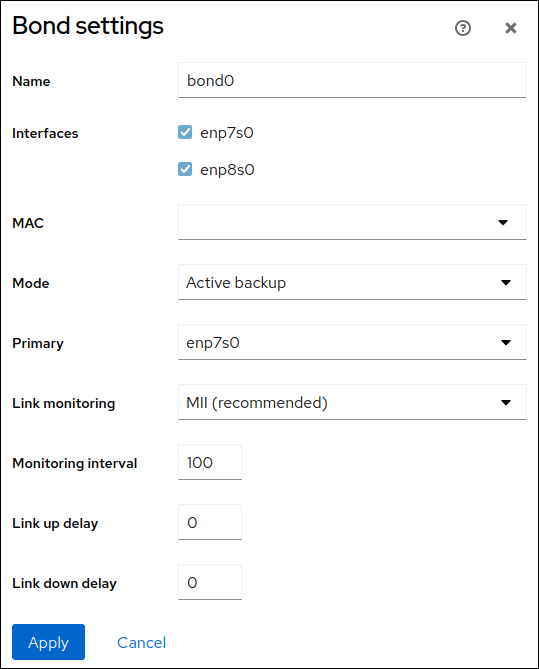
- Click .
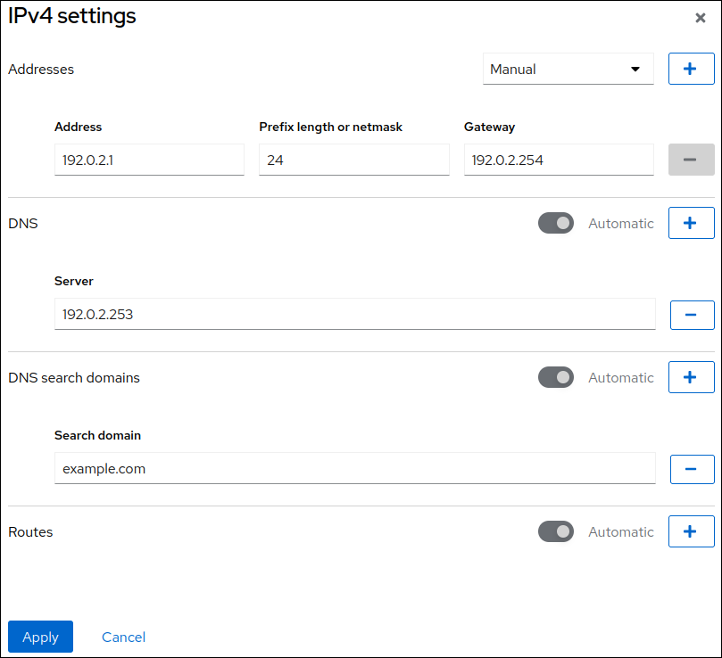
By default, the bond uses a dynamic IP address. If you want to set a static IP address:
- Click the name of the bond in the Interfaces section.
- Click Edit next to the protocol you want to configure.
- Select Manual next to Addresses, and enter the IP address, prefix, and default gateway.
- In the DNS section, click the button, and enter the IP address of the DNS server. Repeat this step to set multiple DNS servers.
- In the DNS search domains section, click the button, and enter the search domain.
If the interface requires static routes, configure them in the Routes section.
- Click
Verification
Select the Networking tab in the navigation on the left side of the screen, and check if there is incoming and outgoing traffic on the interface:

Temporarily remove the network cable from one of the network devices and check if the other device in the bond is handling the traffic.
Note that there is no method to properly test link failure events using software utilities. Tools that deactivate connections, such as the web console, show only the bonding driver’s ability to handle member configuration changes and not actual link failure events.
Display the status of the bond:
# cat /proc/net/bonding/bond0
3.5. Configuring a network bond by using nmtui
The nmtui application provides a text-based user interface for NetworkManager. You can use nmtui to configure a network bond on a host without a graphical interface.
In nmtui:
- Navigate by using the cursor keys.
- Press a button by selecting it and hitting Enter.
- Select and clear checkboxes by using Space.
- To return to the previous screen, use ESC.
Prerequisites
- Two or more physical or virtual network devices are installed on the server.
- To use Ethernet devices as ports of the bond, the physical or virtual Ethernet devices must be installed on the server.
Procedure
If you do not know the network device names on which you want configure a network bond, display the available devices:
# nmcli device status
DEVICE     TYPE      STATE                   CONNECTION
enp7s0     ethernet  unavailable             --
enp8s0     ethernet  unavailable             --
...
Start
nmtui:# nmtui- Select Edit a connection, and press Enter.
- Press Add.
- Select Bond from the list of network types, and press Enter.
Optional: Enter a name for the NetworkManager profile to be created.
On hosts with multiple profiles, a meaningful name makes it easier to identify the purpose of a profile.
- Enter the bond device name to be created into the Device field.
Add ports to the bond to be created:
- Press Add next to the Slaves list.
- Select the type of the interface you want to add as port to the bond, for example, Ethernet.
- Optional: Enter a name for the NetworkManager profile to be created for this bond port.
- Enter the port’s device name into the Device field.
Press OK to return to the window with the bond settings.
Figure 3.1. Adding an Ethernet device as port to a bond
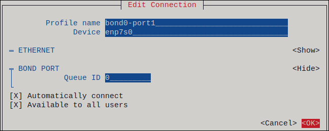
- Repeat these steps to add more ports to the bond.
-
Set the bond mode. Depending on the value you set,
nmtuidisplays additional fields for settings that are related to the selected mode. Depending on your environment, configure the IP address settings in the IPv4 configuration and IPv6 configuration areas accordingly. For this, press the button next to these areas, and select:
-
Disabled, if the bond does not require an IP address. -
Automatic, if a DHCP server or stateless address autoconfiguration (SLAAC) dynamically assigns an IP address to the bond. Manual, if the network requires static IP address settings. In this case, you must fill further fields:- Press Show next to the protocol you want to configure to display additional fields.
Press Add next to Addresses, and enter the IP address and the subnet mask in Classless Inter-Domain Routing (CIDR) format.
If you do not specify a subnet mask, NetworkManager sets a
/32subnet mask for IPv4 addresses and/64for IPv6 addresses.- Enter the address of the default gateway.
- Press Add next to DNS servers, and enter the DNS server address.
- Press Add next to Search domains, and enter the DNS search domain.
Figure 3.2. Example of a bond connection with static IP address settings

-
- Press OK to create and automatically activate the new connection.
- Press Back to return to the main menu.
-
Select Quit, and press Enter to close the
nmtuiapplication.
Verification
Temporarily remove the network cable from one of the network devices and check if the other device in the bond is handling the traffic.
Note that there is no method to properly test link failure events using software utilities. Tools that deactivate connections, such as
nmcli, show only the bonding driver’s ability to handle port configuration changes and not actual link failure events.Display the status of the bond:
# cat /proc/net/bonding/bond0
3.6. Configuring a network bond by using nm-connection-editor
If you use Red Hat Enterprise Linux with a graphical interface, you can configure network bonds using the nm-connection-editor application.
Note that nm-connection-editor can add only new ports to a bond. To use an existing connection profile as a port, create the bond by using the nmcli utility as described in Configuring a network bond by using nmcli.
Prerequisites
- Two or more physical or virtual network devices are installed on the server.
- To use Ethernet devices as ports of the bond, the physical or virtual Ethernet devices must be installed on the server.
- To use team, bond, or VLAN devices as ports of the bond, ensure that these devices are not already configured.
Procedure
Open a terminal, and enter
nm-connection-editor:$ nm-connection-editor- Click the button to add a new connection.
- Select the Bond connection type, and click .
On the Bond tab:
- Optional: Set the name of the bond interface in the Interface name field.
Click the button to add a network interface as a port to the bond.
- Select the connection type of the interface. For example, select Ethernet for a wired connection.
- Optional: Set a connection name for the port.
- If you create a connection profile for an Ethernet device, open the Ethernet tab, and select in the Device field the network interface you want to add as a port to the bond. If you selected a different device type, configure it accordingly. Note that you can only use Ethernet interfaces in a bond that are not configured.
- Click .
Repeat the previous step for each interface you want to add to the bond:
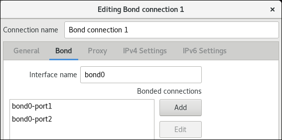
- Optional: Set other options, such as the Media Independent Interface (MII) monitoring interval.
Configure the IP address settings on both the IPv4 Settings and IPv6 Settings tabs:
- If you plan to use this bridge device as a port of other devices, set the Method field to Disabled.
- To use DHCP, leave the Method field at its default, Automatic (DHCP).
To use static IP settings, set the Method field to Manual and fill the fields accordingly:
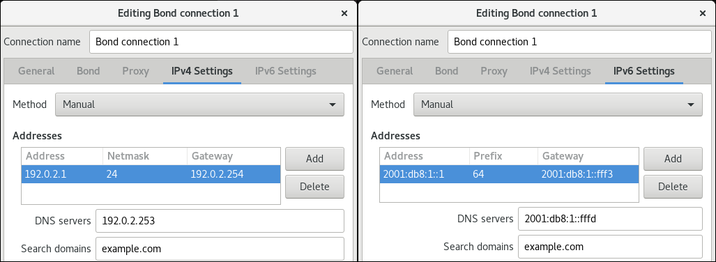
- Click .
-
Close
nm-connection-editor.
Verification
Temporarily remove the network cable from one of the network devices and check if the other device in the bond is handling the traffic.
Note that there is no method to properly test link failure events using software utilities. Tools that deactivate connections, such as
nmcli, show only the bonding driver’s ability to handle port configuration changes and not actual link failure events.Display the status of the bond:
# cat /proc/net/bonding/bond0
3.7. Configuring a network bond by using nmstatectl
Use the nmstatectl utility to configure a network bond through the Nmstate API. The Nmstate API ensures that, after setting the configuration, the result matches the configuration file. If anything fails, nmstatectl automatically rolls back the changes to avoid leaving the system in an incorrect state.
Depending on your environment, adjust the YAML file accordingly. For example, to use different devices than Ethernet adapters in the bond, adapt the base-iface attribute and type attributes of the ports you use in the bond.
Prerequisites
- Two or more physical or virtual network devices are installed on the server.
- To use Ethernet devices as ports in the bond, the physical or virtual Ethernet devices must be installed on the server.
-
To use team, bridge, or VLAN devices as ports in the bond, set the interface name in the
portlist, and define the corresponding interfaces. -
The
nmstatepackage is installed.
Procedure
Create a YAML file, for example
~/create-bond.yml, with the following content:--- interfaces: - name: bond0 type: bond state: up ipv4: enabled: true address: - ip: 192.0.2.1 prefix-length: 24 dhcp: false ipv6: enabled: true address: - ip: 2001:db8:1::1 prefix-length: 64 autoconf: false dhcp: false link-aggregation: mode: active-backup port: - enp1s0 - enp7s0 - name: enp1s0 type: ethernet state: up - name: enp7s0 type: ethernet state: up routes: config: - destination: 0.0.0.0/0 next-hop-address: 192.0.2.254 next-hop-interface: bond0 - destination: ::/0 next-hop-address: 2001:db8:1::fffe next-hop-interface: bond0 dns-resolver: config: search: - example.com server: - 192.0.2.200 - 2001:db8:1::ffbbThese settings define a network bond with the following settings:
-
Network interfaces in the bond:
enp1s0andenp7s0 -
Mode:
active-backup -
Static IPv4 address:
192.0.2.1with a/24subnet mask -
Static IPv6 address:
2001:db8:1::1with a/64subnet mask -
IPv4 default gateway:
192.0.2.254 -
IPv6 default gateway:
2001:db8:1::fffe -
IPv4 DNS server:
192.0.2.200 -
IPv6 DNS server:
2001:db8:1::ffbb -
DNS search domain:
example.com
-
Network interfaces in the bond:
Apply the settings to the system:
# nmstatectl apply ~/create-bond.yml
Verification
Display the status of the devices and connections:
# nmcli device status
DEVICE      TYPE      STATE      CONNECTION
bond0       bond      connected  bond0
Display all settings of the connection profile:
# nmcli connection show bond0
connection.id:              bond0
connection.uuid:            79cbc3bd-302e-4b1f-ad89-f12533b818ee
connection.stable-id:       --
connection.type:            bond
connection.interface-name:  bond0
...
Display the connection settings in YAML format:
# nmstatectl show bond0
Additional resources
-
nmstatectl(8)man page on your system -
/usr/share/doc/nmstate/examples/directory
3.8. Configuring a network bond by using the network RHEL system role
You can combine network interfaces in a bond to provide a logical interface with higher throughput or redundancy. To configure a bond, create a NetworkManager connection profile. By using Ansible and the network RHEL system role, you can automate this process and remotely configure connection profiles on the hosts defined in a playbook.
You can use the network RHEL system role to configure a network bond and, if a connection profile for the bond’s parent device does not exist, the role can create it as well.
Prerequisites
- You have prepared the control node and the managed nodes
- You are logged in to the control node as a user who can run playbooks on the managed nodes.
-
The account you use to connect to the managed nodes has
sudopermissions on them. - Two or more physical or virtual network devices are installed on the server.
Procedure
Create a playbook file, for example
~/playbook.yml, with the following content:--- - name: Configure the network hosts: managed-node-01.example.com tasks: - name: Bond connection profile with two Ethernet ports ansible.builtin.include_role: name: rhel-system-roles.network vars: network_connections: # Bond profile - name: bond0 type: bond interface_name: bond0 ip: dhcp4: yes auto6: yes bond: mode: active-backup state: up # Port profile for the 1st Ethernet device - name: bond0-port1 interface_name: enp7s0 type: ethernet controller: bond0 state: up # Port profile for the 2nd Ethernet device - name: bond0-port2 interface_name: enp8s0 type: ethernet controller: bond0 state: upThe settings specified in the example playbook include the following:
type: <profile_type>- Sets the type of the profile to create. The example playbook creates three connection profiles: One for the bond and two for the Ethernet devices.
dhcp4: yes- Enables automatic IPv4 address assignment from DHCP, PPP, or similar services.
auto6: yes-
Enables IPv6 auto-configuration. By default, NetworkManager uses Router Advertisements. If the router announces the
managedflag, NetworkManager requests an IPv6 address and prefix from a DHCPv6 server. mode: <bond_mode>Sets the bonding mode. Possible values are:
-
balance-rr(default) -
active-backup -
balance-xor -
broadcast -
802.3ad -
balance-tlb -
balance-alb.
Depending on the mode you set, you need to set additional variables in the playbook.
-
For details about all variables used in the playbook, see the
/usr/share/ansible/roles/rhel-system-roles.network/README.mdfile on the control node.Validate the playbook syntax:
$ ansible-playbook --syntax-check ~/playbook.ymlNote that this command only validates the syntax and does not protect against a wrong but valid configuration.
Run the playbook:
$ ansible-playbook ~/playbook.yml
Verification
Temporarily remove the network cable from one of the network devices and check if the other device in the bond is handling the traffic.
Note that there is no method to properly test link failure events using software utilities. Tools that deactivate connections, such as
nmcli, show only the bonding driver’s ability to handle port configuration changes and not actual link failure events.
Additional resources
-
/usr/share/ansible/roles/rhel-system-roles.network/README.mdfile -
/usr/share/doc/rhel-system-roles/network/directory
3.9. Creating a network bond to enable switching between an Ethernet and wireless connection without interrupting the VPN
RHEL users who connect their workstation to their company’s network typically use a VPN to access remote resources. However, if the workstation switches between an Ethernet and Wi-Fi connection, for example, if you release a laptop from a docking station with an Ethernet connection, the VPN connection is interrupted. To avoid this problem, you can create a network bond that uses the Ethernet and Wi-Fi connection in active-backup mode.
Prerequisites
- The host contains an Ethernet and a Wi-Fi device.
An Ethernet and Wi-Fi NetworkManager connection profile has been created and both connections work independently.
This procedure uses the following connection profiles to create a network bond named
bond0:-
Docking_stationassociated with theenp11s0u1Ethernet device -
Wi-Fiassociated with thewlp1s0Wi-Fi device
-
Procedure
Create a bond interface in
active-backupmode:# nmcli connection add type bond con-name bond0 ifname bond0 bond.options "mode=active-backup"This command names both the interface and connection profile
bond0.Configure the IPv4 settings of the bond:
- If a DHCP server in your network assigns IPv4 addresses to hosts, no action is required.
If your local network requires static IPv4 addresses, set the address, network mask, default gateway, DNS server, and DNS search domain to the
bond0connection:# nmcli connection modify bond0 ipv4.addresses '192.0.2.1/24' # nmcli connection modify bond0 ipv4.gateway '192.0.2.254' # nmcli connection modify bond0 ipv4.dns '192.0.2.253' # nmcli connection modify bond0 ipv4.dns-search 'example.com' # nmcli connection modify bond0 ipv4.method manual
Configure the IPv6 settings of the bond:
- If your router or a DHCP server in your network assigns IPv6 addresses to hosts, no action is required.
If your local network requires static IPv6 addresses, set the address, network mask, default gateway, DNS server, and DNS search domain to the
bond0connection:# nmcli connection modify bond0 ipv6.addresses '2001:db8:1::1/64' # nmcli connection modify bond0 ipv6.gateway '2001:db8:1::fffe' # nmcli connection modify bond0 ipv6.dns '2001:db8:1::fffd' # nmcli connection modify bond0 ipv6.dns-search 'example.com' # nmcli connection modify bond0 ipv6.method manual
Display the connection profiles:
# nmcli connection show
NAME             UUID                                  TYPE      DEVICE
Docking_station  256dd073-fecc-339d-91ae-9834a00407f9  ethernet  enp11s0u1
Wi-Fi            1f1531c7-8737-4c60-91af-2d21164417e8  wifi      wlp1s0
...
You require the names of the connection profiles and the Ethernet device name in the next steps.
Assign the connection profile of the Ethernet connection to the bond:
# nmcli connection modify Docking_station controller bond0Assign the connection profile of the Wi-Fi connection to the bond:
# nmcli connection modify Wi-Fi controller bond0If your Wi-Fi network uses MAC filtering to allow only MAC addresses on a allow list to access the network, configure that NetworkManager dynamically assigns the MAC address of the active port to the bond:
# nmcli connection modify bond0 +bond.options fail_over_mac=1With this setting, you must set only the MAC address of the Wi-Fi device to the allow list instead of the MAC address of both the Ethernet and Wi-Fi device.
Set the device associated with the Ethernet connection as primary device of the bond:
# nmcli con modify bond0 +bond.options "primary=enp11s0u1"With this setting, the bond always uses the Ethernet connection if it is available.
Configure that NetworkManager automatically activates ports when the
bond0device is activated:# nmcli connection modify bond0 connection.autoconnect-ports 1Activate the
bond0connection:# nmcli connection up bond0
Verification
Display the currently active device, the status of the bond and its ports:
# cat /proc/net/bonding/bond0
Ethernet Channel Bonding Driver: v3.7.1 (April 27, 2011)

Bonding Mode: fault-tolerance (active-backup) (fail_over_mac active)
Primary Slave: enp11s0u1 (primary_reselect always)
Currently Active Slave: enp11s0u1
MII Status: up
MII Polling Interval (ms): 1
Up Delay (ms): 0
Down Delay (ms): 0
Peer Notification Delay (ms): 0

Slave Interface: enp11s0u1
MII Status: up
Speed: 1000 Mbps
Duplex: full
Link Failure Count: 0
Permanent HW addr: 00:53:00:59:da:b7
Slave queue ID: 0

Slave Interface: wlp1s0
MII Status: up
Speed: Unknown
Duplex: Unknown
Link Failure Count: 2
Permanent HW addr: 00:53:00:b3:22:ba
Slave queue ID: 0
Additional resources
3.10. The different network bonding modes
The Linux bonding driver provides link aggregation. Bonding is the process of aggregating multiple network interfaces in parallel to provide a single logical bonded interface. The actions of a bonded interface depend on the bonding policy that is also known as mode. The different modes provide either load-balancing or hot standby services.
The Linux bonding driver supports the following modes:
- Balance-rr (Mode 0)
Balance-rruses the round-robin algorithm that sequentially transmits packets from the first available port to the last one. This mode provides load balancing and fault tolerance.This mode requires switch configuration of a port aggregation group, also called EtherChannel or similar port grouping. An EtherChannel is a port link aggregation technology to group multiple physical Ethernet links to one logical Ethernet link.
The drawback of this mode is that it is not suitable for heavy workloads and if TCP throughput or ordered packet delivery is essential.
- Active-backup (Mode 1)
Active-backupuses the policy that determines that only one port is active in the bond. This mode provides fault tolerance and does not require any switch configuration.If the active port fails, an alternate port becomes active. The bond sends a gratuitous address resolution protocol (ARP) response to the network. The gratuitous ARP forces the receiver of the ARP frame to update their forwarding table. The
Active-backupmode transmits a gratuitous ARP to announce the new path to maintain connectivity for the host.The
primaryoption defines the preferred port of the bonding interface.- Balance-xor (Mode 2)
Balance-xoruses the selected transmit hash policy to send the packets. This mode provides load balancing, fault tolerance, and requires switch configuration to set up an Etherchannel or similar port grouping.To alter packet transmission and balance transmit, this mode uses the
xmit_hash_policyoption. Depending on the source or destination of traffic on the interface, the interface requires an additional load-balancing configuration. See description xmit_hash_policy bonding parameter.- Broadcast (Mode 3)
Broadcastuses a policy that transmits every packet on all interfaces. This mode provides fault tolerance and requires a switch configuration to set up an EtherChannel or similar port grouping.The drawback of this mode is that it is not suitable for heavy workloads and if TCP throughput or ordered packet delivery is essential.
- 802.3ad (Mode 4)
802.3aduses the same-named IEEE standard dynamic link aggregation policy. This mode provides fault tolerance. This mode requires switch configuration to set up a Link Aggregation Control Protocol (LACP) port grouping.This mode creates aggregation groups that share the same speed and duplex settings and utilizes all ports in the active aggregator. Depending on the source or destination of traffic on the interface, this mode requires an additional load-balancing configuration.
By default, the port selection for outgoing traffic depends on the transmit hash policy. Use the
xmit_hash_policyoption of the transmit hash policy to change the port selection and balance transmit.The difference between the
802.3adand theBalance-xoris compliance. The802.3adpolicy negotiates LACP between the port aggregation groups. See description xmit_hash_policy bonding parameter- Balance-tlb (Mode 5)
Balance-tlbuses the transmit load balancing policy. This mode provides fault tolerance, load balancing, and establishes channel bonding that does not require any switch support.The active port receives the incoming traffic. In case of failure of the active port, another one takes over the MAC address of the failed port. To decide which interface processes the outgoing traffic, use one of the following modes:
-
Value
0: Uses the hash distribution policy to distribute traffic without load balancing Value
1: Distributes traffic to each port by using load balancingWith the bonding option
tlb_dynamic_lb=0, this bonding mode uses thexmit_hash_policybonding option to balance transmit. Theprimaryoption defines the preferred port of the bonding interface.
See description xmit_hash_policy bonding parameter.
-
Value
- Balance-alb (Mode 6)
Balance-albuses an adaptive load balancing policy. This mode provides fault tolerance, load balancing, and does not require any special switch support.This mode includes balance-transmit load balancing (
balance-tlb) and receive-load balancing for IPv4 and IPv6 traffic. The bonding intercepts ARP replies sent by the local system and overwrites the source hardware address of one of the ports in the bond. ARP negotiation manages the receive-load balancing. Therefore, different ports use different hardware addresses for the server.The
primaryoption defines the preferred port of the bonding interface. With the bonding optiontlb_dynamic_lb=0, this bonding mode uses thexmit_hash_policybonding option to balance transmit. See description xmit_hash_policy bonding parameter.
Additionally, you can use NetworkManager to configure the following mode:
- Balance-slb
The source load balancing (SLB) bonding mode distributes outgoing data streams across multiple network interfaces based on the source address of the traffic and a VLAN hash. This mode does not require any switch configuration.
NetworkManager uses the
balance-xormode in combination withnftablesrules to provide SLB. For details about configuring this mode, see Configuring a network bond on RHEL with source load balancing.
Additional resources
-
/usr/share/doc/kernel-doc-<version>/Documentation/networking/bonding.rstprovided by thekernel-docpackage -
/usr/share/doc/kernel-doc-<version>/Documentation/networking/bonding.txtprovided by thekernel-docpackage - Which bonding modes work when used with a bridge that virtual machine guests or containers connect to? (Red Hat Knowledgebase)
- How are the values for different policies in "xmit_hash_policy" bonding parameter calculated? (Red Hat Knowledgebase)
3.11. The xmit_hash_policy bonding parameter
The xmit_hash_policy load balancing parameter selects the transmit hash policy for a node selection in the balance-xor, 802.3ad, balance-alb, and balance-tlb modes. It is only applicable to mode 5 and 6 if the tlb_dynamic_lb parameter is 0. The possible values of this parameter are layer2, layer2+3, layer3+4, encap2+3, encap3+4, and vlan+srcmac.
Refer the table for details:
| Policy or Network layers | Layer2 | Layer2+3 | Layer3+4 | encap2+3 | encap3+4 | VLAN+srcmac |
| Uses | XOR of source and destination MAC addresses and Ethernet protocol type | XOR of source and destination MAC addresses and IP addresses | XOR of source and destination ports and IP addresses |
XOR of source and destination MAC addresses and IP addresses inside a supported tunnel, for example, Virtual Extensible LAN (VXLAN). This mode relies on |
XOR of source and destination ports and IP addresses inside a supported tunnel, for example, VXLAN. This mode relies on | XOR of VLAN ID and source MAC vendor and source MAC device |
| Placement of traffic | All traffic to a particular network peer on the same underlying network interface | All traffic to a particular IP address on the same underlying network interface | All traffic to a particular IP address and port on the same underlying network interface | |||
| Primary choice | If network traffic is between this system and multiple other systems in the same broadcast domain | If network traffic between this system and multiple other systems goes through a default gateway | If network traffic between this system and another system uses the same IP addresses but goes through multiple ports | The encapsulated traffic is between the source system and multiple other systems using multiple IP addresses | The encapsulated traffic is between the source system and other systems using multiple port numbers | If the bond carries network traffic, from multiple containers or virtual machines (VM), that expose their MAC address directly to the external network such as the bridge network, and you can not configure a switch for Mode 2 or Mode 4 |
| Secondary choice | If network traffic is mostly between this system and multiple other systems behind a default gateway | If network traffic is mostly between this system and another system | ||||
| Compliant | 802.3ad | 802.3ad | Not 802.3ad | |||
| Default policy | This is the default policy if no configuration is provided |
For non-IP traffic, the formula is the same as for the |
For non-IP traffic, the formula is the same as for the |
Chapter 4. Configuring a NIC team
Network interface controller (NIC) teaming is a method to combine or aggregate physical and virtual network interfaces to provide a logical interface with higher throughput or redundancy. NIC teaming uses a small kernel module to implement fast handling of packet flows and a user-space service for other tasks. This way, NIC teaming is an easily extensible and scalable solution for load-balancing and redundancy requirements.
Red Hat Enterprise Linux provides administrators different options to configure team devices. For example:
-
Use
nmclito configure teams connections using the command line. - Use the RHEL web console to configure team connections using a web browser.
-
Use the
nm-connection-editorapplication to configure team connections in a graphical interface.
NIC teaming is deprecated in Red Hat Enterprise Linux 9. Consider using the network bonding driver as an alternative. For details, see Configuring a network bond.
4.1. Migrating a NIC team configuration to network bond
Network interface controller (NIC) teaming is deprecated in Red Hat Enterprise Linux 9. If you already have a working NIC team configured, for example because you upgraded from an earlier RHEL version, you can migrate the configuration to a network bond that is managed by NetworkManager.
The team2bond utility only converts the team configuration to a bond. Afterwards, you must manually configure further settings of the bond, such as IP addresses and DNS configuration.
Prerequisites
-
The
team-team0NetworkManager connection profile is configured and manages theteam0device. -
The
teamdpackage is installed.
Procedure
Optional: Display the IP configuration of the
team-team0NetworkManager connection:# nmcli connection show team-team0 | grep -E "^ip" ... ipv4.method: manual ipv4.dns: 192.0.2.253 ipv4.dns-search: example.com ipv4.addresses: 192.0.2.1/24 ipv4.gateway: 192.0.2.254 ... ipv6.method: manual ipv6.dns: 2001:db8:1::fffd ipv6.dns-search: example.com ipv6.addresses: 2001:db8:1::1/64 ipv6.gateway: 2001:db8:1::fffe ...Export the configuration of the
team0device to a JSON file:# teamdctl team0 config dump actual > /tmp/team0.jsonRemove the NIC team. For example, if you configured the team in NetworkManager, remove the
team-team0connection profile and the profiles of associated ports:# nmcli connection delete team-team0 # nmcli connection delete team-team0-port1 # nmcli connection delete team-team0-port2
Run the
team2bondutility in dry-run mode to displaynmclicommands that set up a network bond with similar settings as the team device:# team2bond --config=/tmp/team0.json --rename=bond0 nmcli con add type bond ifname bond0 bond.options "mode=active-backup,num_grat_arp=1,num_unsol_na=1,resend_igmp=1,miimon=100,miimon=100" nmcli con add type ethernet ifname enp7s0 controller bond0 nmcli con add type ethernet ifname enp8s0 controller bond0
The first command contains two
miimonoptions because the team configuration file contained twolink_watchentries. Note that this does not affect the creation of the bond.If you bound services to the device name of the team and want to avoid updating or breaking these services, omit the
--rename=bond0option. In this case,team2bonduses the same interface name for the bond as for the team.-
Verify that the options for the bond the
team2bondutility suggested are correct. Create the bond. You can execute the suggested
nmclicommands or re-run theteam2bondcommand with the--exec-cmdoption:# team2bond --config=/tmp/team0.json --rename=bond0 --exec-cmd Connection 'bond-bond0' (0241a531-0c72-4202-80df-73eadfc126b5) successfully added. Connection 'bond-port-enp7s0' (38489729-b624-4606-a784-1ccf01e2f6d6) successfully added. Connection 'bond-port-enp8s0' (de97ec06-7daa-4298-9a71-9d4c7909daa1) successfully added.
You require the name of the bond connection profile (
bond-bond0) in the next steps.Set the IPv4 settings that were previously configured on
team-team0to thebond-bond0connection:# nmcli connection modify bond-bond0 ipv4.addresses '192.0.2.1/24' # nmcli connection modify bond-bond0 ipv4.gateway '192.0.2.254' # nmcli connection modify bond-bond0 ipv4.dns '192.0.2.253' # nmcli connection modify bond-bond0 ipv4.dns-search 'example.com' # nmcli connection modify bond-bond0 ipv4.method manual
Set the IPv6 settings that were previously configured on
team-team0to thebond-bond0connection:# nmcli connection modify bond-bond0 ipv6.addresses '2001:db8:1::1/64' # nmcli connection modify bond-bond0 ipv6.gateway '2001:db8:1::fffe' # nmcli connection modify bond-bond0 ipv6.dns '2001:db8:1::fffd' # nmcli connection modify bond-bond0 ipv6.dns-search 'example.com' # nmcli connection modify bond-bond0 ipv6.method manual
Activate the connection:
# nmcli connection up bond-bond0
Verification
Display the IP configuration of the
bond-bond0NetworkManager connection:# nmcli connection show bond-bond0 | grep -E "^ip" ... ipv4.method: manual ipv4.dns: 192.0.2.253 ipv4.dns-search: example.com ipv4.addresses: 192.0.2.1/24 ipv4.gateway: 192.0.2.254 ... ipv6.method: manual ipv6.dns: 2001:db8:1::fffd ipv6.dns-search: example.com ipv6.addresses: 2001:db8:1::1/64 ipv6.gateway: 2001:db8:1::fffe ...Display the status of the bond:
# cat /proc/net/bonding/bond0
Ethernet Channel Bonding Driver: v5.13.0-0.rc7.51.el9.x86_64

Bonding Mode: fault-tolerance (active-backup)
Primary Slave: None
Currently Active Slave: enp7s0
MII Status: up
MII Polling Interval (ms): 100
Up Delay (ms): 0
Down Delay (ms): 0
Peer Notification Delay (ms): 0

Slave Interface: enp7s0
MII Status: up
Speed: Unknown
Duplex: Unknown
Link Failure Count: 0
Permanent HW addr: 52:54:00:bf:b1:a9
Slave queue ID: 0

Slave Interface: enp8s0
MII Status: up
Speed: Unknown
Duplex: Unknown
Link Failure Count: 0
Permanent HW addr: 52:54:00:04:36:0f
Slave queue ID: 0
In this example, both ports are up.
To verify that bonding failover works:
- Temporarily remove the network cable from the host. Note that there is no method to properly test link failure events using the command line.
Display the status of the bond:
# cat /proc/net/bonding/bond0
4.2. Understanding the default behavior of controller and port interfaces
Consider the following default behavior when managing or troubleshooting team or bond port interfaces using the NetworkManager service:
- Starting the controller interface does not automatically start the port interfaces.
- Starting a port interface always starts the controller interface.
- Stopping the controller interface also stops the port interface.
- A controller without ports can start static IP connections.
- A controller without ports waits for ports when starting DHCP connections.
- A controller with a DHCP connection waiting for ports completes when you add a port with a carrier.
- A controller with a DHCP connection waiting for ports continues waiting when you add a port without a carrier.
4.3. Understanding the teamd service, runners, and link-watchers
The team service, teamd, controls one instance of the team driver. This instance of the driver adds instances of a hardware device driver to form a team of network interfaces. The team driver presents a network interface, for example team0, to the kernel.
The teamd service implements the common logic to all methods of teaming. Those functions are unique to the different load sharing and backup methods, such as round-robin, and implemented by separate units of code referred to as runners. Administrators specify runners in JavaScript Object Notation (JSON) format, and the JSON code is compiled into an instance of teamd when the instance is created. Alternatively, when using NetworkManager, you can set the runner in the team.runner parameter, and NetworkManager auto-creates the corresponding JSON code.
The following runners are available:
-
broadcast: Transmits data over all ports. -
roundrobin: Transmits data over all ports in turn. -
activebackup: Transmits data over one port while the others are kept as a backup. -
loadbalance: Transmits data over all ports with active Tx load balancing and Berkeley Packet Filter (BPF)-based Tx port selectors. -
random: Transmits data on a randomly selected port. -
lacp: Implements the 802.3ad Link Aggregation Control Protocol (LACP).
The teamd services uses a link watcher to monitor the state of subordinate devices. The following link-watchers are available:
-
ethtool: Thelibteamlibrary uses theethtoolutility to watch for link state changes. This is the default link-watcher. -
arp_ping: Thelibteamlibrary uses thearp_pingutility to monitor the presence of a far-end hardware address using Address Resolution Protocol (ARP). -
nsna_ping: On IPv6 connections, thelibteamlibrary uses the Neighbor Advertisement and Neighbor Solicitation features from the IPv6 Neighbor Discovery protocol to monitor the presence of a neighbor’s interface.
Each runner can use any link watcher, with the exception of lacp. This runner can only use the ethtool link watcher.
4.4. Configuring a NIC team by using nmcli
To configure a network interface controller (NIC) team on the command line, use the nmcli utility.
NIC teaming is deprecated in Red Hat Enterprise Linux 9. Consider using the network bonding driver as an alternative. For details, see Configuring a network bond.
Prerequisites
-
The
teamdandNetworkManager-teampackages are installed. - Two or more physical or virtual network devices are installed on the server.
- To use Ethernet devices as ports of the team, the physical or virtual Ethernet devices must be installed on the server and connected to a switch.
To use bond, bridge, or VLAN devices as ports of the team, you can either create these devices while you create the team or you can create them in advance as described in:
Procedure
Create a team interface:
# nmcli connection add type team con-name team0 ifname team0 team.runner activebackupThis command creates a NIC team named
team0that uses theactivebackuprunner.Optional: Set a link watcher. For example, to set the
ethtoollink watcher in theteam0connection profile:# nmcli connection modify team0 team.link-watchers "name=ethtool"Link watchers support different parameters. To set parameters for a link watcher, specify them space-separated in the
nameproperty. Note that the name property must be surrounded by quotation marks. For example, to use theethtoollink watcher and set itsdelay-upparameter to2500milliseconds (2.5 seconds):# nmcli connection modify team0 team.link-watchers "name=ethtool delay-up=2500"To set multiple link watchers and each of them with specific parameters, the link watchers must be separated by a comma. The following example sets the
ethtoollink watcher with thedelay-upparameter and thearp_pinglink watcher with thesource-hostandtarget-hostparameter:# nmcli connection modify team0 team.link-watchers "name=ethtool delay-up=2, name=arp_ping source-host=192.0.2.1 target-host=192.0.2.2"Display the network interfaces, and note the names of the interfaces you want to add to the team:
# nmcli device status
DEVICE  TYPE      STATE         CONNECTION
enp7s0  ethernet  disconnected  --
enp8s0  ethernet  disconnected  --
bond0   bond      connected  bond0
bond1   bond      connected  bond1
...
In this example:
-
enp7s0andenp8s0are not configured. To use these devices as ports, add connection profiles in the next step. Note that you can only use Ethernet interfaces in a team that are not assigned to any connection. -
bond0andbond1have existing connection profiles. To use these devices as ports, modify their profiles in the next step.
-
Assign the port interfaces to the team:
If the interfaces you want to assign to the team are not configured, create new connection profiles for them:
# nmcli connection add type ethernet port-type team con-name team0-port1 ifname enp7s0 controller team0
# nmcli connection add type ethernet port--type team con-name team0-port2 ifname enp8s0 controller team0
These commands create profiles for
enp7s0andenp8s0, and add them to theteam0connection.To assign an existing connection profile to the team:
Set the
controllerparameter of these connections toteam0:# nmcli connection modify bond0 controller team0 # nmcli connection modify bond1 controller team0
These commands assign the existing connection profiles named
bond0andbond1to theteam0connection.Reactivate the connections:
# nmcli connection up bond0
# nmcli connection up bond1
Configure the IPv4 settings:
If you plan to use this team device as a port of other devices, enter:
# nmcli connection modify team0 ipv4.method disabled- To use DHCP, no action is required.
To set a static IPv4 address, network mask, default gateway, and DNS server to the
team0connection, enter:# nmcli connection modify team0 ipv4.addresses '192.0.2.1/24' ipv4.gateway '192.0.2.254' ipv4.dns '192.0.2.253' ipv4.dns-search 'example.com' ipv4.method manual
Configure the IPv6 settings:
If you plan to use this team device as a port of other devices, enter:
# nmcli connection modify team0 ipv6.method disabled- To use stateless address autoconfiguration (SLAAC), no action is required.
To set a static IPv6 address, network mask, default gateway, and DNS server to the
team0connection, enter:# nmcli connection modify team0 ipv6.addresses '2001:db8:1::1/64' ipv6.gateway '2001:db8:1::fffe' ipv6.dns '2001:db8:1::fffd' ipv6.dns-search 'example.com' ipv6.method manual
Activate the connection:
# nmcli connection up team0
Verification
Display the status of the team:
# teamdctl team0 state
setup:
  runner: activebackup
ports:
  enp7s0
    link watches:
      link summary: up
      instance[link_watch_0]:
        name: ethtool
        link: up
        down count: 0
  enp8s0
    link watches:
      link summary: up
      instance[link_watch_0]:
        name: ethtool
        link: up
        down count: 0
runner:
  active port: enp7s0
In this example, both ports are up.
Additional resources
- Configuring NetworkManager to avoid using a specific profile to provide a default gateway
- Understanding the teamd service, runners, and link-watchers
-
nm-settings(5)andteamd.conf(5)man pages on your system
4.5. Configuring a NIC team by using the RHEL web console
Use the RHEL web console to configure a network interface controller (NIC) team if you prefer to manage network settings using a web browser-based interface.
NIC teaming is deprecated in Red Hat Enterprise Linux 9. Consider using the network bonding driver as an alternative. For details, see Configuring a network bond.
Prerequisites
-
The
teamdandNetworkManager-teampackages are installed. - Two or more physical or virtual network devices are installed on the server.
- To use Ethernet devices as ports of the team, the physical or virtual Ethernet devices must be installed on the server and connected to a switch.
To use bond, bridge, or VLAN devices as ports of the team, create them in advance as described in:
- You have installed the RHEL 9 web console.
- You have enabled the cockpit service.
Your user account is allowed to log in to the web console.
For instructions, see Installing and enabling the web console.
Procedure
Log in to the RHEL 9 web console.
For details, see Logging in to the web console.
-
Select the
Networkingtab in the navigation on the left side of the screen. -
Click in the
Interfacessection. - Enter the name of the team device you want to create.
- Select the interfaces that should be ports of the team.
Select the runner of the team.
If you select
Load balancingor802.3ad LACP, the web console shows the additional fieldBalancer.Set the link watcher:
-
If you select
Ethtool, additionally, set a link up and link down delay. -
If you set
ARP pingorNSNA ping, additionally, set a ping interval and ping target.

-
If you select
- Click .
By default, the team uses a dynamic IP address. If you want to set a static IP address:
-
Click the name of the team in the
Interfacessection. -
Click
Editnext to the protocol you want to configure. -
Select
Manualnext toAddresses, and enter the IP address, prefix, and default gateway. -
In the
DNSsection, click the button, and enter the IP address of the DNS server. Repeat this step to set multiple DNS servers. -
In the
DNS search domainssection, click the button, and enter the search domain. If the interface requires static routes, configure them in the
Routessection.- Click
-
Click the name of the team in the
Verification
Select the
Networkingtab in the navigation on the left side of the screen, and check if there is incoming and outgoing traffic on the interface.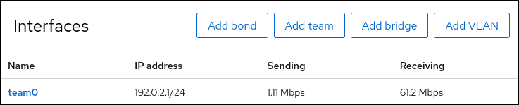
Display the status of the team:
# teamdctl team0 state
setup:
  runner: activebackup
ports:
  enp7s0
    link watches:
      link summary: up
      instance[link_watch_0]:
        name: ethtool
        link: up
        down count: 0
  enp8s0
    link watches:
      link summary: up
      instance[link_watch_0]:
        name: ethtool
        link: up
        down count: 0
runner:
  active port: enp7s0
In this example, both ports are up.
Additional resources
4.6. Configuring a NIC team by using nm-connection-editor
If you use Red Hat Enterprise Linux with a graphical interface, you can configure network interface controller (NIC) teams using the nm-connection-editor application.
Note that nm-connection-editor can add only new ports to a team. To use an existing connection profile as a port, create the team using the nmcli utility as described in Configuring a NIC team by using nmcli.
NIC teaming is deprecated in Red Hat Enterprise Linux 9. Consider using the network bonding driver as an alternative. For details, see Configuring a network bond.
Prerequisites
-
The
teamdandNetworkManager-teampackages are installed. - Two or more physical or virtual network devices are installed on the server.
- To use Ethernet devices as ports of the team, the physical or virtual Ethernet devices must be installed on the server.
- To use team, bond, or VLAN devices as ports of the team, ensure that these devices are not already configured.
Procedure
Open a terminal, and enter
nm-connection-editor:$ nm-connection-editor- Click the button to add a new connection.
- Select the Team connection type, and click .
On the Team tab:
- Optional: Set the name of the team interface in the Interface name field.
Click the button to add a new connection profile for a network interface and adding the profile as a port to the team.
- Select the connection type of the interface. For example, select Ethernet for a wired connection.
- Optional: Set a connection name for the port.
- If you create a connection profile for an Ethernet device, open the Ethernet tab, and select in the Device field the network interface you want to add as a port to the team. If you selected a different device type, configure it accordingly. Note that you can only use Ethernet interfaces in a team that are not assigned to any connection.
- Click .
Repeat the previous step for each interface you want to add to the team.
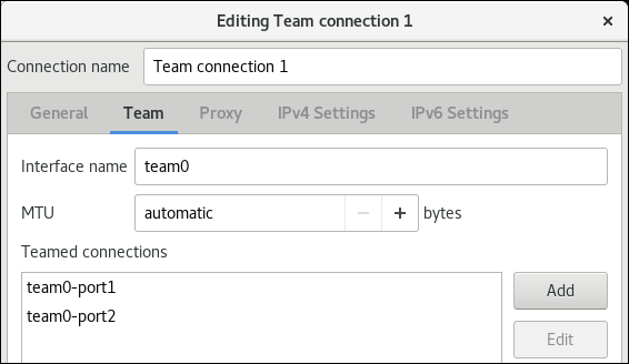
Click the button to set advanced options to the team connection.
- On the Runner tab, select the runner.
- On the Link Watcher tab, set the link watcher and its optional settings.
- Click .
Configure the IP address settings on both the IPv4 Settings and IPv6 Settings tabs:
- If you plan to use this bridge device as a port of other devices, set the Method field to Disabled.
- To use DHCP, leave the Method field at its default, Automatic (DHCP).
To use static IP settings, set the Method field to Manual and fill the fields accordingly:

- Click .
-
Close
nm-connection-editor.
Verification
Display the status of the team:
# teamdctl team0 state
setup:
  runner: activebackup
ports:
  enp7s0
    link watches:
      link summary: up
      instance[link_watch_0]:
        name: ethtool
        link: up
        down count: 0
  enp8s0
    link watches:
      link summary: up
      instance[link_watch_0]:
        name: ethtool
        link: up
        down count: 0
runner:
  active port: enp7s0
Additional resources
- Configuring a network bond by using nm-connection-editor
- Configuring a NIC team by using nm-connection-editor
- Configuring VLAN tagging by using nm-connection-editor
- Configuring NetworkManager to avoid using a specific profile to provide a default gateway
- Understanding the teamd service, runners, and link-watchers
- NetworkManager duplicates a connection after restart of NetworkManager service (Red Hat Knowledgebase)
Chapter 5. Configuring VLAN tagging
A Virtual Local Area Network (VLAN) is a logical network within a physical network. The VLAN interface tags packets with the VLAN ID as they pass through the interface, and removes tags of returning packets. You create VLAN interfaces on top of another interface, such as Ethernet, bond, team, or bridge devices. These interfaces are called the parent interface.
Red Hat Enterprise Linux provides administrators different options to configure VLAN devices. For example:
-
Use
nmclito configure VLAN tagging using the command line. - Use the RHEL web console to configure VLAN tagging using a web browser.
-
Use
nmtuito configure VLAN tagging in a text-based user interface. -
Use the
nm-connection-editorapplication to configure connections in a graphical interface. -
Use
nmstatectlto configure connections through the Nmstate API. - Use RHEL system roles to automate the VLAN configuration on one or multiple hosts.
5.1. Configuring VLAN tagging by using nmcli
You can configure Virtual Local Area Network (VLAN) tagging on the command line using the nmcli utility.
Prerequisites
- The interface you plan to use as a parent to the virtual VLAN interface supports VLAN tags.
If you configure the VLAN on top of a bond interface:
- The ports of the bond are up.
-
The bond is not configured with the
fail_over_mac=followoption. A VLAN virtual device cannot change its MAC address to match the parent’s new MAC address. In such a case, the traffic would still be sent with the incorrect source MAC address. -
The bond is usually not expected to get IP addresses from a DHCP server or IPv6 auto-configuration. Ensure it by setting the
ipv4.method=disableandipv6.method=ignoreoptions while creating the bond. Otherwise, if DHCP or IPv6 auto-configuration fails after some time, the interface might be brought down.
- The switch, the host is connected to, is configured to support VLAN tags. For details, see the documentation of your switch.
Procedure
Display the network interfaces:
# nmcli device status
DEVICE   TYPE      STATE         CONNECTION
enp1s0   ethernet  disconnected  enp1s0
bridge0  bridge    connected     bridge0
bond0    bond      connected     bond0
...
Create the VLAN interface. For example, to create a VLAN interface named
vlan10that usesenp1s0as its parent interface and that tags packets with VLAN ID10, enter:# nmcli connection add type vlan con-name vlan10 ifname vlan10 vlan.parent enp1s0 vlan.id 10Note that the VLAN must be within the range from
0to4094.By default, the VLAN connection inherits the maximum transmission unit (MTU) from the parent interface. Optionally, set a different MTU value:
# nmcli connection modify vlan10 ethernet.mtu 2000Configure the IPv4 settings:
If you plan to use this VLAN device as a port of other devices, enter:
# nmcli connection modify vlan10 ipv4.method disabled- To use DHCP, no action is required.
To set a static IPv4 address, network mask, default gateway, and DNS server to the
vlan10connection, enter:# nmcli connection modify vlan10 ipv4.addresses '192.0.2.1/24' ipv4.gateway '192.0.2.254' ipv4.dns '192.0.2.253' ipv4.method manual
Configure the IPv6 settings:
If you plan to use this VLAN device as a port of other devices, enter:
# nmcli connection modify vlan10 ipv6.method disabled- To use stateless address autoconfiguration (SLAAC), no action is required.
To set a static IPv6 address, network mask, default gateway, and DNS server to the
vlan10connection, enter:# nmcli connection modify vlan10 ipv6.addresses '2001:db8:1::1/32' ipv6.gateway '2001:db8:1::fffe' ipv6.dns '2001:db8:1::fffd' ipv6.method manual
Activate the connection:
# nmcli connection up vlan10
Verification
Verify the settings:
# ip -d addr show vlan10
4: vlan10@enp1s0: <BROADCAST,MULTICAST,UP,LOWER_UP> mtu 1500 qdisc noqueue state UP group default qlen 1000
    link/ether 52:54:00:72:2f:6e brd ff:ff:ff:ff:ff:ff promiscuity 0
    vlan protocol 802.1Q id 10 <REORDER_HDR> numtxqueues 1 numrxqueues 1 gso_max_size 65536 gso_max_segs 65535
    inet 192.0.2.1/24 brd 192.0.2.255 scope global noprefixroute vlan10
       valid_lft forever preferred_lft forever
    inet6 2001:db8:1::1/32 scope global noprefixroute
       valid_lft forever preferred_lft forever
    inet6 fe80::8dd7:9030:6f8e:89e6/64 scope link noprefixroute
       valid_lft forever preferred_lft forever
Additional resources
-
nm-settings(5)man page on your system
5.2. Configuring nested VLANs by using nmcli
802.1ad is a protocol used for Virtual Local Area Network (VLAN) tagging. It is also known as Q-in-Q tagging. You can use this technology to create multiple VLAN tags within a single Ethernet frame to achieve the following benefits:
- Increased network scalability by creating multiple isolated network segments within a VLAN. This enables you to segment and organize large networks into smaller, manageable units.
- Improved traffic management by isolating and controlling different types of network traffic. This can improve the network performance and reduce network congestion.
- Efficient resource utilization by enabling the creation of smaller, more targeted network segments.
- Enhanced security by isolating network traffic and reducing the risk of unauthorized access to sensitive data.
Prerequisites
- The interface you plan to use as a parent to the virtual VLAN interface supports VLAN tags.
If you configure the VLAN on top of a bond interface:
- The ports of the bond are up.
-
The bond is not configured with the
fail_over_mac=followoption. A VLAN virtual device cannot change its MAC address to match the parent’s new MAC address. In such a case, the traffic would still be sent with the incorrect source MAC address. -
The bond is usually not expected to get IP addresses from a DHCP server or IPv6 auto-configuration. Ensure it by setting the
ipv4.method=disableandipv6.method=ignoreoptions while creating the bond. Otherwise, if DHCP or IPv6 auto-configuration fails after some time, the interface might be brought down.
- The switch, the host is connected to, is configured to support VLAN tags. For details, see the documentation of your switch.
Procedure
Display the physical network devices:
# nmcli device status
DEVICE   TYPE      STATE         CONNECTION
enp1s0  ethernet  connected      enp1s0
...
Create the base VLAN interface. For example, to create a base VLAN interface named
vlan10that usesenp1s0as its parent interface and that tags packets with VLAN ID10, enter:# nmcli connection add type vlan con-name vlan10 dev enp1s0 vlan.id 10Note that the VLAN must be within the range from
0to4094.By default, the VLAN connection inherits the maximum transmission unit (MTU) from the parent interface. Optionally, set a different MTU value:
# nmcli connection modify vlan10 ethernet.mtu 2000Create the nested VLAN interface on top of the base VLAN interface:
# nmcli connection add type vlan con-name vlan10.20 dev enp1s0.10 id 20 vlan.protocol 802.1adThis command creates a new VLAN connection with a name of
vlan10.20and a VLAN ID of20on the parent VLAN connectionvlan10. Thedevoption specifies the parent network device. In this case it isenp1s0.10. Thevlan.protocoloption specifies the VLAN encapsulation protocol. In this case it is802.1ad(Q-in-Q).Configure the IPv4 settings of the nested VLAN interface:
- To use DHCP, no action is required.
To set a static IPv4 address, network mask, default gateway, and DNS server to the
vlan10.20connection, enter:# nmcli connection modify vlan10.20 ipv4.method manual ipv4.addresses 192.0.2.1/24 ipv4.gateway 192.0.2.254 ipv4.dns 192.0.2.200
Configure the IPv6 settings of the nested VLAN interface:
- To use stateless address autoconfiguration (SLAAC), no action is required.
To set a static IPv4 address, network mask, default gateway, and DNS server to the vlan10 connection, enter:
# nmcli connection modify vlan10 ipv4.addresses '192.0.2.1/24' ipv4.gateway '192.0.2.254' ipv4.dns '192.0.2.253' ipv4.method manual
Activate the profile:
# nmcli connection up vlan10.20
Verification
Verify the configuration of the nested VLAN interface:
# ip -d addr show enp1s0.10.20
10: enp1s0.10.20@enp1s0.10: <BROADCAST,MULTICAST,UP,LOWER_UP> mtu 1500 qdisc noqueue state UP group default qlen 1000
    link/ether 52:54:00:d2:74:3e brd ff:ff:ff:ff:ff:ff promiscuity 0 minmtu 0 maxmtu 65535
    vlan protocol 802.1ad id 20 <REORDER_HDR> numtxqueues 1 numrxqueues 1 gso_max_size 65536 gso_max_segs 65535 tso_max_size 65536 tso_max_segs 65535 gro_max_size 65536
    inet 192.0.2.1/24 brd 192.0.2.255 scope global noprefixroute enp1s0.10.20
       valid_lft forever preferred_lft forever
    inet6 2001:db8:1::1/32 scope global noprefixroute
       valid_lft forever preferred_lft forever
    inet6 fe80::ce3b:84c5:9ef8:d0e6/64 scope link noprefixroute
       valid_lft forever preferred_lft forever
Additional resources
-
nm-settings(5)man page on your system
5.3. Configuring VLAN tagging by using the RHEL web console
You can configure VLAN tagging if you prefer to manage network settings using a web browser-based interface in the RHEL web console.
Prerequisites
- The interface you plan to use as a parent to the virtual VLAN interface supports VLAN tags.
If you configure the VLAN on top of a bond interface:
- The ports of the bond are up.
-
The bond is not configured with the
fail_over_mac=followoption. A VLAN virtual device cannot change its MAC address to match the parent’s new MAC address. In such a case, the traffic would still be sent with the incorrect source MAC address. - The bond is usually not expected to get IP addresses from a DHCP server or IPv6 auto-configuration. Ensure it by disabling the IPv4 and IPv6 protocol creating the bond. Otherwise, if DHCP or IPv6 auto-configuration fails after some time, the interface might be brought down.
- The switch, the host is connected to, is configured to support VLAN tags. For details, see the documentation of your switch.
- You have installed the RHEL 9 web console.
- You have enabled the cockpit service.
Your user account is allowed to log in to the web console.
For instructions, see Installing and enabling the web console.
Procedure
Log in to the RHEL 9 web console.
For details, see Logging in to the web console.
-
Select the
Networkingtab in the navigation on the left side of the screen. -
Click in the
Interfacessection. - Select the parent device.
- Enter the VLAN ID.
Enter the name of the VLAN device or keep the automatically-generated name.
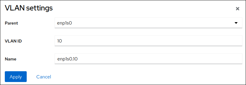
- Click .
By default, the VLAN device uses a dynamic IP address. If you want to set a static IP address:
-
Click the name of the VLAN device in the
Interfacessection. -
Click
Editnext to the protocol you want to configure. -
Select
Manualnext toAddresses, and enter the IP address, prefix, and default gateway. -
In the
DNSsection, click the button, and enter the IP address of the DNS server. Repeat this step to set multiple DNS servers. -
In the
DNS search domainssection, click the button, and enter the search domain. If the interface requires static routes, configure them in the
Routessection.- Click
-
Click the name of the VLAN device in the
Verification
Select the
Networkingtab in the navigation on the left side of the screen, and check if there is incoming and outgoing traffic on the interface: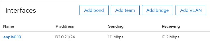
5.4. Configuring VLAN tagging by using nmtui
The nmtui application provides a text-based user interface for NetworkManager. You can use nmtui to configure VLAN tagging on a host without a graphical interface.
In nmtui:
- Navigate by using the cursor keys.
- Press a button by selecting it and hitting Enter.
- Select and clear checkboxes by using Space.
- To return to the previous screen, use ESC.
Prerequisites
- The interface you plan to use as a parent to the virtual VLAN interface supports VLAN tags.
If you configure the VLAN on top of a bond interface:
- The ports of the bond are up.
-
The bond is not configured with the
fail_over_mac=followoption. A VLAN virtual device cannot change its MAC address to match the parent’s new MAC address. In such a case, the traffic would still be sent with the then incorrect source MAC address. -
The bond is usually not expected to get IP addresses from a DHCP server or IPv6 auto-configuration. Ensure it by setting the
ipv4.method=disableandipv6.method=ignoreoptions while creating the bond. Otherwise, if DHCP or IPv6 auto-configuration fails after some time, the interface might be brought down.
- The switch the host is connected to is configured to support VLAN tags. For details, see the documentation of your switch.
Procedure
If you do not know the network device name on which you want configure VLAN tagging, display the available devices:
# nmcli device status
DEVICE     TYPE      STATE                   CONNECTION
enp1s0     ethernet  unavailable             --
...
Start
nmtui:# nmtui- Select Edit a connection, and press Enter.
- Press Add.
- Select VLAN from the list of network types, and press Enter.
Optional: Enter a name for the NetworkManager profile to be created.
On hosts with multiple profiles, a meaningful name makes it easier to identify the purpose of a profile.
- Enter the VLAN device name to be created into the Device field.
- Enter the name of the device on which you want to configure VLAN tagging into the Parent field.
-
Enter the VLAN ID. The ID must be within the range from
0to4094. Depending on your environment, configure the IP address settings in the IPv4 configuration and IPv6 configuration areas accordingly. For this, press the button next to these areas, and select:
-
Disabled, if this VLAN device does not require an IP address or you want to use it as a port of other devices. -
Automatic, if a DHCP server or stateless address autoconfiguration (SLAAC) dynamically assigns an IP address to the VLAN device. Manual, if the network requires static IP address settings. In this case, you must fill further fields:- Press Show next to the protocol you want to configure to display additional fields.
Press Add next to Addresses, and enter the IP address and the subnet mask in Classless Inter-Domain Routing (CIDR) format.
If you do not specify a subnet mask, NetworkManager sets a
/32subnet mask for IPv4 addresses and/64for IPv6 addresses.- Enter the address of the default gateway.
- Press Add next to DNS servers, and enter the DNS server address.
- Press Add next to Search domains, and enter the DNS search domain.
Figure 5.1. Example of a VLAN connection with static IP address settings

-
- Press OK to create and automatically activate the new connection.
- Press Back to return to the main menu.
-
Select Quit, and press Enter to close the
nmtuiapplication.
Verification
Verify the settings:
# ip -d addr show vlan10
4: vlan10@enp1s0: <BROADCAST,MULTICAST,UP,LOWER_UP> mtu 1500 qdisc noqueue state UP group default qlen 1000
    link/ether 52:54:00:72:2f:6e brd ff:ff:ff:ff:ff:ff promiscuity 0
    vlan protocol 802.1Q id 10 <REORDER_HDR> numtxqueues 1 numrxqueues 1 gso_max_size 65536 gso_max_segs 65535
    inet 192.0.2.1/24 brd 192.0.2.255 scope global noprefixroute vlan10
       valid_lft forever preferred_lft forever
    inet6 2001:db8:1::1/32 scope global noprefixroute
       valid_lft forever preferred_lft forever
    inet6 fe80::8dd7:9030:6f8e:89e6/64 scope link noprefixroute
       valid_lft forever preferred_lft forever
5.5. Configuring VLAN tagging by using nm-connection-editor
You can configure Virtual Local Area Network (VLAN) tagging in a graphical interface using the nm-connection-editor application.
Prerequisites
- The interface you plan to use as a parent to the virtual VLAN interface supports VLAN tags.
If you configure the VLAN on top of a bond interface:
- The ports of the bond are up.
-
The bond is not configured with the
fail_over_mac=followoption. A VLAN virtual device cannot change its MAC address to match the parent’s new MAC address. In such a case, the traffic would still be sent with the incorrect source MAC address.
- The switch, the host is connected, to is configured to support VLAN tags. For details, see the documentation of your switch.
Procedure
Open a terminal, and enter
nm-connection-editor:$ nm-connection-editor- Click the button to add a new connection.
- Select the VLAN connection type, and click .
On the VLAN tab:
- Select the parent interface.
- Select the VLAN id. Note that the VLAN must be within the range from 0 to 4094.
- By default, the VLAN connection inherits the maximum transmission unit (MTU) from the parent interface. Optionally, set a different MTU value.
Optional: Set the name of the VLAN interface and further VLAN-specific options.
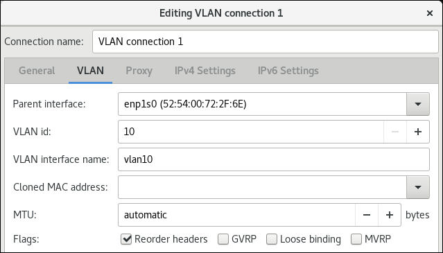
Configure the IP address settings on both the IPv4 Settings and IPv6 Settings tabs:
- If you plan to use this bridge device as a port of other devices, set the Method field to Disabled.
- To use DHCP, leave the Method field at its default, Automatic (DHCP).
To use static IP settings, set the Method field to Manual and fill the fields accordingly:
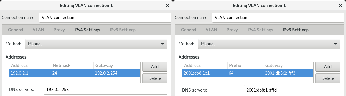
- Click .
-
Close
nm-connection-editor.
Verification
Verify the settings:
# ip -d addr show vlan10
4: vlan10@enp1s0: <BROADCAST,MULTICAST,UP,LOWER_UP> mtu 1500 qdisc noqueue state UP group default qlen 1000
    link/ether 52:54:00:d5:e0:fb brd ff:ff:ff:ff:ff:ff promiscuity 0
    vlan protocol 802.1Q id 10 <REORDER_HDR> numtxqueues 1 numrxqueues 1 gso_max_size 65536 gso_max_segs 65535
    inet 192.0.2.1/24 brd 192.0.2.255 scope global noprefixroute vlan10
       valid_lft forever preferred_lft forever
    inet6 2001:db8:1::1/32 scope global noprefixroute
       valid_lft forever preferred_lft forever
    inet6 fe80::8dd7:9030:6f8e:89e6/64 scope link noprefixroute
       valid_lft forever preferred_lft forever
5.6. Configuring VLAN tagging by using nmstatectl
Use the nmstatectl utility to configure Virtual Local Area Network VLAN through the Nmstate API. The Nmstate API ensures that, after setting the configuration, the result matches the configuration file. If anything fails, nmstatectl automatically rolls back the changes to avoid leaving the system in an incorrect state.
Depending on your environment, adjust the YAML file accordingly. For example, to use different devices than Ethernet adapters in the VLAN, adapt the base-iface attribute and type attributes of the ports you use in the VLAN.
Prerequisites
- To use Ethernet devices as ports in the VLAN, the physical or virtual Ethernet devices must be installed on the server.
-
The
nmstatepackage is installed.
Procedure
Create a YAML file, for example
~/create-vlan.yml, with the following content:--- interfaces: - name: vlan10 type: vlan state: up ipv4: enabled: true address: - ip: 192.0.2.1 prefix-length: 24 dhcp: false ipv6: enabled: true address: - ip: 2001:db8:1::1 prefix-length: 64 autoconf: false dhcp: false vlan: base-iface: enp1s0 id: 10 - name: enp1s0 type: ethernet state: up routes: config: - destination: 0.0.0.0/0 next-hop-address: 192.0.2.254 next-hop-interface: vlan10 - destination: ::/0 next-hop-address: 2001:db8:1::fffe next-hop-interface: vlan10 dns-resolver: config: search: - example.com server: - 192.0.2.200 - 2001:db8:1::ffbbThese settings define a VLAN with ID 10 that uses the
enp1s0device. As the child device, the VLAN connection has the following settings:-
A static IPv4 address -
192.0.2.1with the/24subnet mask -
A static IPv6 address -
2001:db8:1::1with the/64subnet mask -
An IPv4 default gateway -
192.0.2.254 -
An IPv6 default gateway -
2001:db8:1::fffe -
An IPv4 DNS server -
192.0.2.200 -
An IPv6 DNS server -
2001:db8:1::ffbb -
A DNS search domain -
example.com
-
A static IPv4 address -
Apply the settings to the system:
# nmstatectl apply ~/create-vlan.yml
Verification
Display the status of the devices and connections:
# nmcli device status
DEVICE      TYPE      STATE      CONNECTION
vlan10      vlan      connected  vlan10
Display all settings of the connection profile:
# nmcli connection show vlan10
connection.id:              vlan10
connection.uuid:            1722970f-788e-4f81-bd7d-a86bf21c9df5
connection.stable-id:       --
connection.type:            vlan
connection.interface-name:  vlan10
...
Display the connection settings in YAML format:
# nmstatectl show vlan0
Additional resources
-
nmstatectl(8)man page on your system -
/usr/share/doc/nmstate/examples/directory
5.7. Configuring VLAN tagging by using the network RHEL system role
If your network uses Virtual Local Area Networks (VLANs) to separate network traffic into logical networks, create a NetworkManager connection profile to configure VLAN tagging. By using Ansible and the network RHEL system role, you can automate this process and remotely configure connection profiles on the hosts defined in a playbook.
You can use the network RHEL system role to configure VLAN tagging and, if a connection profile for the VLAN’s parent device does not exist, the role can create it as well.
If the VLAN device requires an IP address, default gateway, and DNS settings, configure them on the VLAN device and not on the parent device.
Prerequisites
- You have prepared the control node and the managed nodes
- You are logged in to the control node as a user who can run playbooks on the managed nodes.
-
The account you use to connect to the managed nodes has
sudopermissions on them.
Procedure
Create a playbook file, for example
~/playbook.yml, with the following content:--- - name: Configure the network hosts: managed-node-01.example.com tasks: - name: VLAN connection profile with Ethernet port ansible.builtin.include_role: name: rhel-system-roles.network vars: network_connections: # Ethernet profile - name: enp1s0 type: ethernet interface_name: enp1s0 autoconnect: yes state: up ip: dhcp4: no auto6: no # VLAN profile - name: enp1s0.10 type: vlan vlan: id: 10 ip: dhcp4: yes auto6: yes parent: enp1s0 state: upThe settings specified in the example playbook include the following:
type: <profile_type>- Sets the type of the profile to create. The example playbook creates two connection profiles: One for the parent Ethernet device and one for the VLAN device.
dhcp4: <value>-
If set to
yes, automatic IPv4 address assignment from DHCP, PPP, or similar services is enabled. Disable the IP address configuration on the parent device. auto6: <value>-
If set to
yes, IPv6 auto-configuration is enabled. In this case, by default, NetworkManager uses Router Advertisements and, if the router announces themanagedflag, NetworkManager requests an IPv6 address and prefix from a DHCPv6 server. Disable the IP address configuration on the parent device. parent: <parent_device>- Sets the parent device of the VLAN connection profile. In the example, the parent is the Ethernet interface.
For details about all variables used in the playbook, see the
/usr/share/ansible/roles/rhel-system-roles.network/README.mdfile on the control node.Validate the playbook syntax:
$ ansible-playbook --syntax-check ~/playbook.ymlNote that this command only validates the syntax and does not protect against a wrong but valid configuration.
Run the playbook:
$ ansible-playbook ~/playbook.yml
Verification
Verify the VLAN settings:
# ansible managed-node-01.example.com -m command -a 'ip -d addr show enp1s0.10'
managed-node-01.example.com | CHANGED | rc=0 >>
4: vlan10@enp1s0: <BROADCAST,MULTICAST,UP,LOWER_UP> mtu 1500 qdisc noqueue state UP group default qlen 1000
    link/ether 52:54:00:72:2f:6e brd ff:ff:ff:ff:ff:ff promiscuity 0
    vlan protocol 802.1Q id 10 <REORDER_HDR> numtxqueues 1 numrxqueues 1 gso_max_size 65536 gso_max_segs 65535
    ...
Additional resources
-
/usr/share/ansible/roles/rhel-system-roles.network/README.mdfile -
/usr/share/doc/rhel-system-roles/network/directory
Chapter 6. Configuring a network bridge
A network bridge is a link-layer device which forwards traffic between networks based on a table of MAC addresses. The bridge builds the MAC addresses table by listening to network traffic and thereby learning what hosts are connected to each network. For example, you can use a software bridge on a Red Hat Enterprise Linux host to emulate a hardware bridge or in virtualization environments, to integrate virtual machines (VM) to the same network as the host.
A bridge requires a network device in each network the bridge should connect. When you configure a bridge, the bridge is called controller and the devices it uses ports.
You can create bridges on different types of devices, such as:
- Physical and virtual Ethernet devices
- Network bonds
- Network teams
- VLAN devices
Due to the IEEE 802.11 standard which specifies the use of 3-address frames in Wi-Fi for the efficient use of airtime, you cannot configure a bridge over Wi-Fi networks operating in Ad-Hoc or Infrastructure modes.
6.1. Configuring a network bridge by using nmcli
To configure a network bridge on the command line, use the nmcli utility.
Prerequisites
- Two or more physical or virtual network devices are installed on the server.
-
The host runs on Red Hat Enterprise Linux 9.4 or later. This version introduced the
port-type,controller,connection.autoconnect-portsoptions used in this procedure. Previous RHEL versions instead useslave-type,master, andconnection.autoconnect-slaves. - To use Ethernet devices as ports of the bridge, the physical or virtual Ethernet devices must be installed on the server.
To use team, bond, or VLAN devices as ports of the bridge, you can either create these devices while you create the bridge or you can create them in advance as described in:
Procedure
Create a bridge interface:
# nmcli connection add type bridge con-name bridge0 ifname bridge0This command creates a bridge named
bridge0, enter:Display the network interfaces, and note the names of the interfaces you want to add to the bridge:
# nmcli device status
DEVICE  TYPE      STATE         CONNECTION
enp7s0  ethernet  disconnected  --
enp8s0  ethernet  disconnected  --
bond0   bond      connected     bond0
bond1   bond      connected     bond1
...
In this example:
-
enp7s0andenp8s0are not configured. To use these devices as ports, add connection profiles in the next step. -
bond0andbond1have existing connection profiles. To use these devices as ports, modify their profiles in the next step.
-
Assign the interfaces to the bridge.
If the interfaces you want to assign to the bridge are not configured, create new connection profiles for them:
# nmcli connection add type ethernet port-type bridge con-name bridge0-port1 ifname enp7s0 controller bridge0
# nmcli connection add type ethernet port-type bridge con-name bridge0-port2 ifname enp8s0 controller bridge0
These commands create profiles for
enp7s0andenp8s0, and add them to thebridge0connection.If you want to assign an existing connection profile to the bridge:
Set the
controllerparameter of these connections tobridge0:# nmcli connection modify bond0 controller bridge0 # nmcli connection modify bond1 controller bridge0
These commands assign the existing connection profiles named
bond0andbond1to thebridge0connection.Reactivate the connections:
# nmcli connection up bond0
# nmcli connection up bond1
Configure the IPv4 settings:
If you plan to use this bridge device as a port of other devices, enter:
# nmcli connection modify bridge0 ipv4.method disabled- To use DHCP, no action is required.
To set a static IPv4 address, network mask, default gateway, and DNS server to the
bridge0connection, enter:# nmcli connection modify bridge0 ipv4.addresses '192.0.2.1/24' ipv4.gateway '192.0.2.254' ipv4.dns '192.0.2.253' ipv4.dns-search 'example.com' ipv4.method manual
Configure the IPv6 settings:
If you plan to use this bridge device as a port of other devices, enter:
# nmcli connection modify bridge0 ipv6.method disabled- To use stateless address autoconfiguration (SLAAC), no action is required.
To set a static IPv6 address, network mask, default gateway, and DNS server to the
bridge0connection, enter:# nmcli connection modify bridge0 ipv6.addresses '2001:db8:1::1/64' ipv6.gateway '2001:db8:1::fffe' ipv6.dns '2001:db8:1::fffd' ipv6.dns-search 'example.com' ipv6.method manual
Optional: Configure further properties of the bridge. For example, to set the Spanning Tree Protocol (STP) priority of
bridge0to16384, enter:# nmcli connection modify bridge0 bridge.priority '16384'By default, STP is enabled.
Activate the connection:
# nmcli connection up bridge0Verify that the ports are connected, and the
CONNECTIONcolumn displays the port’s connection name:# nmcli device DEVICE TYPE STATE CONNECTION ... enp7s0 ethernet connected bridge0-port1 enp8s0 ethernet connected bridge0-port2When you activate any port of the connection, NetworkManager also activates the bridge, but not the other ports of it. You can configure that Red Hat Enterprise Linux enables all ports automatically when the bridge is enabled:
Enable the
connection.autoconnect-portsparameter of the bridge connection:# nmcli connection modify bridge0 connection.autoconnect-ports 1Reactivate the bridge:
# nmcli connection up bridge0
Verification
Use the
iputility to display the link status of Ethernet devices that are ports of a specific bridge:# ip link show master bridge0 3: enp7s0: <BROADCAST,MULTICAST,UP,LOWER_UP> mtu 1500 qdisc fq_codel master bridge0 state UP mode DEFAULT group default qlen 1000 link/ether 52:54:00:62:61:0e brd ff:ff:ff:ff:ff:ff 4: enp8s0: <BROADCAST,MULTICAST,UP,LOWER_UP> mtu 1500 qdisc fq_codel master bridge0 state UP mode DEFAULT group default qlen 1000 link/ether 52:54:00:9e:f1:ce brd ff:ff:ff:ff:ff:ffUse the
bridgeutility to display the status of Ethernet devices that are ports of any bridge device:# bridge link show 3: enp7s0: <BROADCAST,MULTICAST,UP,LOWER_UP> mtu 1500 master bridge0 state forwarding priority 32 cost 100 4: enp8s0: <BROADCAST,MULTICAST,UP,LOWER_UP> mtu 1500 master bridge0 state listening priority 32 cost 100 5: enp9s0: <BROADCAST,MULTICAST,UP,LOWER_UP> mtu 1500 master bridge1 state forwarding priority 32 cost 100 6: enp11s0: <BROADCAST,MULTICAST,UP,LOWER_UP> mtu 1500 master bridge1 state blocking priority 32 cost 100 ...To display the status for a specific Ethernet device, use the
bridge link show dev <ethernet_device_name>command.
Additional resources
-
bridge(8)andnm-settings(5)man pages on your system - NetworkManager duplicates a connection after restart of NetworkManager service (Red Hat Knowledgebase)
- How to configure a bridge with VLAN information? (Red Hat Knowledgebase)
6.2. Configuring a network bridge by using the RHEL web console
Use the RHEL web console to configure a network bridge if you prefer to manage network settings using a web browser-based interface.
Prerequisites
- Two or more physical or virtual network devices are installed on the server.
- To use Ethernet devices as ports of the bridge, the physical or virtual Ethernet devices must be installed on the server.
To use team, bond, or VLAN devices as ports of the bridge, you can either create these devices while you create the bridge or you can create them in advance as described in:
- You have installed the RHEL 9 web console.
- You have enabled the cockpit service.
Your user account is allowed to log in to the web console.
For instructions, see Installing and enabling the web console.
Procedure
Log in to the RHEL 9 web console.
For details, see Logging in to the web console.
- Select the Networking tab in the navigation on the left side of the screen.
- Click in the Interfaces section.
- Enter the name of the bridge device you want to create.
- Select the interfaces that should be ports of the bridge.
Optional: Enable the Spanning tree protocol (STP) feature to avoid bridge loops and broadcast radiation.
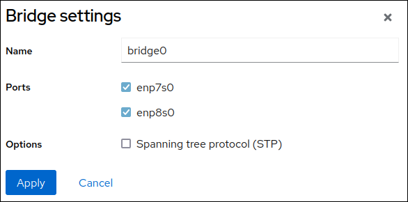
- Click .
By default, the bridge uses a dynamic IP address. If you want to set a static IP address:
- Click the name of the bridge in the Interfaces section.
- Click Edit next to the protocol you want to configure.
- Select Manual next to Addresses, and enter the IP address, prefix, and default gateway.
- In the DNS section, click the button, and enter the IP address of the DNS server. Repeat this step to set multiple DNS servers.
- In the DNS search domains section, click the button, and enter the search domain.
If the interface requires static routes, configure them in the Routes section.
- Click
Verification
Select the Networking tab in the navigation on the left side of the screen, and check if there is incoming and outgoing traffic on the interface:

6.3. Configuring a network bridge by using nmtui
The nmtui application provides a text-based user interface for NetworkManager. You can use nmtui to configure a network bridge on a host without a graphical interface.
In nmtui:
- Navigate by using the cursor keys.
- Press a button by selecting it and hitting Enter.
- Select and clear checkboxes by using Space.
- To return to the previous screen, use ESC.
Prerequisites
- Two or more physical or virtual network devices are installed on the server.
- To use Ethernet devices as ports of the bridge, the physical or virtual Ethernet devices must be installed on the server.
Procedure
If you do not know the network device names on which you want configure a network bridge, display the available devices:
# nmcli device status
DEVICE     TYPE      STATE                   CONNECTION
enp7s0     ethernet  unavailable             --
enp8s0     ethernet  unavailable             --
...
Start
nmtui:# nmtui-
Select
Edit a connection, and press Enter. -
Press
Add. -
Select
Bridgefrom the list of network types, and press Enter. Optional: Enter a name for the NetworkManager profile to be created.
On hosts with multiple profiles, a meaningful name makes it easier to identify the purpose of a profile.
-
Enter the bridge device name to be created into the
Devicefield. Add ports to the bridge to be created:
-
Press
Addnext to theSlaveslist. -
Select the type of the interface you want to add as port to the bridge, for example,
Ethernet. - Optional: Enter a name for the NetworkManager profile to be created for this bridge port.
-
Enter the port’s device name into the
Devicefield. Press
OKto return to the window with the bridge settings.Figure 6.1. Adding an Ethernet device as port to a bridge
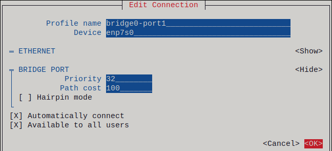
- Repeat these steps to add more ports to the bridge.
-
Press
Depending on your environment, configure the IP address settings in the
IPv4 configurationandIPv6 configurationareas accordingly. For this, press the button next to these areas, and select:-
Disabled, if the bridge does not require an IP address. -
Automatic, if a DHCP server or stateless address autoconfiguration (SLAAC) dynamically assigns an IP address to the bridge. Manual, if the network requires static IP address settings. In this case, you must fill further fields:-
Press
Shownext to the protocol you want to configure to display additional fields. Press
Addnext toAddresses, and enter the IP address and the subnet mask in Classless Inter-Domain Routing (CIDR) format.If you do not specify a subnet mask, NetworkManager sets a
/32subnet mask for IPv4 addresses and/64for IPv6 addresses.- Enter the address of the default gateway.
-
Press
Addnext toDNS servers, and enter the DNS server address. -
Press
Addnext toSearch domains, and enter the DNS search domain.
-
Press
Figure 6.2. Example of a bridge connection without IP address settings
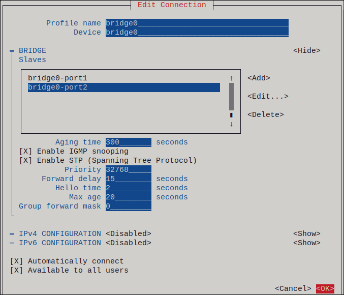
-
-
Press
OKto create and automatically activate the new connection. -
Press
Backto return to the main menu. -
Select
Quit, and press Enter to close thenmtuiapplication.
Verification
Use the
iputility to display the link status of Ethernet devices that are ports of a specific bridge:# ip link show master bridge0 3: enp7s0: <BROADCAST,MULTICAST,UP,LOWER_UP> mtu 1500 qdisc fq_codel master bridge0 state UP mode DEFAULT group default qlen 1000 link/ether 52:54:00:62:61:0e brd ff:ff:ff:ff:ff:ff 4: enp8s0: <BROADCAST,MULTICAST,UP,LOWER_UP> mtu 1500 qdisc fq_codel master bridge0 state UP mode DEFAULT group default qlen 1000 link/ether 52:54:00:9e:f1:ce brd ff:ff:ff:ff:ff:ffUse the
bridgeutility to display the status of Ethernet devices that are ports of any bridge device:# bridge link show 3: enp7s0: <BROADCAST,MULTICAST,UP,LOWER_UP> mtu 1500 master bridge0 state forwarding priority 32 cost 100 4: enp8s0: <BROADCAST,MULTICAST,UP,LOWER_UP> mtu 1500 master bridge0 state listening priority 32 cost 100 ...To display the status for a specific Ethernet device, use the
bridge link show dev <ethernet_device_name>command.
6.4. Configuring a network bridge by using nm-connection-editor
If you use Red Hat Enterprise Linux with a graphical interface, you can configure network bridges using the nm-connection-editor application.
Note that nm-connection-editor can add only new ports to a bridge. To use an existing connection profile as a port, create the bridge using the nmcli utility as described in Configuring a network bridge by using nmcli.
Prerequisites
- Two or more physical or virtual network devices are installed on the server.
- To use Ethernet devices as ports of the bridge, the physical or virtual Ethernet devices must be installed on the server.
- To use team, bond, or VLAN devices as ports of the bridge, ensure that these devices are not already configured.
Procedure
Open a terminal, and enter
nm-connection-editor:$ nm-connection-editor- Click the button to add a new connection.
- Select the Bridge connection type, and click .
On the Bridge tab:
- Optional: Set the name of the bridge interface in the Interface name field.
Click the button to create a new connection profile for a network interface and adding the profile as a port to the bridge.
- Select the connection type of the interface. For example, select Ethernet for a wired connection.
- Optional: Set a connection name for the port device.
- If you create a connection profile for an Ethernet device, open the Ethernet tab, and select in the Device field the network interface you want to add as a port to the bridge. If you selected a different device type, configure it accordingly.
- Click .
Repeat the previous step for each interface you want to add to the bridge.
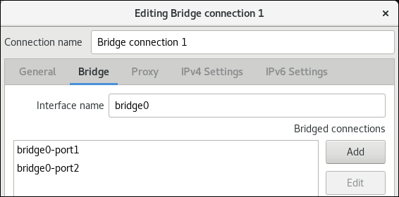
- Optional: Configure further bridge settings, such as Spanning Tree Protocol (STP) options.
Configure the IP address settings on both the IPv4 Settings and IPv6 Settings tabs:
- If you plan to use this bridge device as a port of other devices, set the Method field to Disabled.
- To use DHCP, leave the Method field at its default, Automatic (DHCP).
To use static IP settings, set the Method field to Manual and fill the fields accordingly:
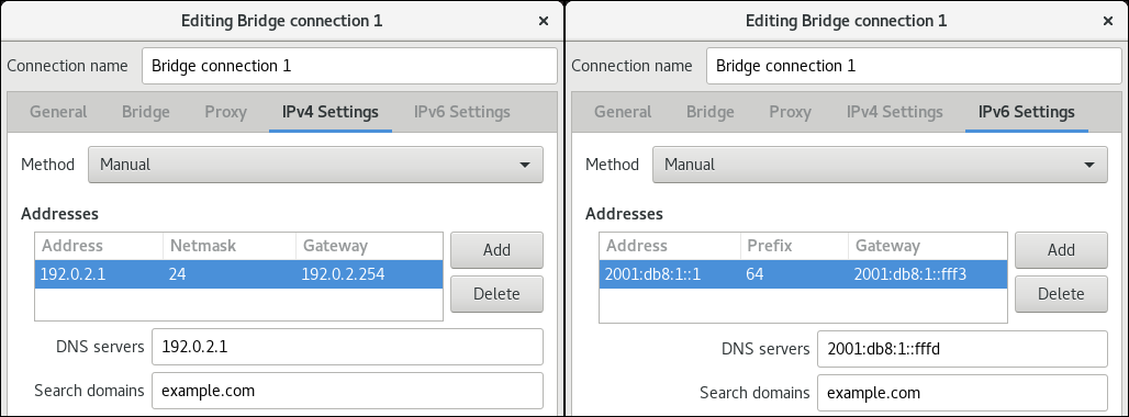
- Click .
-
Close
nm-connection-editor.
Verification
Use the
iputility to display the link status of Ethernet devices that are ports of a specific bridge.# ip link show master bridge0 3: enp7s0: <BROADCAST,MULTICAST,UP,LOWER_UP> mtu 1500 qdisc fq_codel master bridge0 state UP mode DEFAULT group default qlen 1000 link/ether 52:54:00:62:61:0e brd ff:ff:ff:ff:ff:ff 4: enp8s0: <BROADCAST,MULTICAST,UP,LOWER_UP> mtu 1500 qdisc fq_codel master bridge0 state UP mode DEFAULT group default qlen 1000 link/ether 52:54:00:9e:f1:ce brd ff:ff:ff:ff:ff:ffUse the
bridgeutility to display the status of Ethernet devices that are ports in any bridge device:# bridge link show 3: enp7s0: <BROADCAST,MULTICAST,UP,LOWER_UP> mtu 1500 master bridge0 state forwarding priority 32 cost 100 4: enp8s0: <BROADCAST,MULTICAST,UP,LOWER_UP> mtu 1500 master bridge0 state listening priority 32 cost 100 5: enp9s0: <BROADCAST,MULTICAST,UP,LOWER_UP> mtu 1500 master bridge1 state forwarding priority 32 cost 100 6: enp11s0: <BROADCAST,MULTICAST,UP,LOWER_UP> mtu 1500 master bridge1 state blocking priority 32 cost 100 ...To display the status for a specific Ethernet device, use the
bridge link show dev ethernet_device_namecommand.
Additional resources
- Configuring a network bond by using nm-connection-editor
- Configuring a network team by using nm-connection-editor
- Configuring VLAN tagging by using nm-connection-editor
- Configuring NetworkManager to avoid using a specific profile to provide a default gateway
- How to configure a bridge with VLAN information? (Red Hat Knowledgebase)
6.5. Configuring a network bridge by using nmstatectl
Use the nmstatectl utility to configure a network bridge through the Nmstate API. The Nmstate API ensures that, after setting the configuration, the result matches the configuration file. If anything fails, nmstatectl automatically rolls back the changes to avoid leaving the system in an incorrect state.
Depending on your environment, adjust the YAML file accordingly. For example, to use different devices than Ethernet adapters in the bridge, adapt the base-iface attribute and type attributes of the ports you use in the bridge.
Prerequisites
- Two or more physical or virtual network devices are installed on the server.
- To use Ethernet devices as ports in the bridge, the physical or virtual Ethernet devices must be installed on the server.
-
To use team, bond, or VLAN devices as ports in the bridge, set the interface name in the
portlist, and define the corresponding interfaces. -
The
nmstatepackage is installed.
Procedure
Create a YAML file, for example
~/create-bridge.yml, with the following content:--- interfaces: - name: bridge0 type: linux-bridge state: up ipv4: enabled: true address: - ip: 192.0.2.1 prefix-length: 24 dhcp: false ipv6: enabled: true address: - ip: 2001:db8:1::1 prefix-length: 64 autoconf: false dhcp: false bridge: options: stp: enabled: true port: - name: enp1s0 - name: enp7s0 - name: enp1s0 type: ethernet state: up - name: enp7s0 type: ethernet state: up routes: config: - destination: 0.0.0.0/0 next-hop-address: 192.0.2.254 next-hop-interface: bridge0 - destination: ::/0 next-hop-address: 2001:db8:1::fffe next-hop-interface: bridge0 dns-resolver: config: search: - example.com server: - 192.0.2.200 - 2001:db8:1::ffbbThese settings define a network bridge with the following settings:
-
Network interfaces in the bridge:
enp1s0andenp7s0 - Spanning Tree Protocol (STP): Enabled
-
Static IPv4 address:
192.0.2.1with the/24subnet mask -
Static IPv6 address:
2001:db8:1::1with the/64subnet mask -
IPv4 default gateway:
192.0.2.254 -
IPv6 default gateway:
2001:db8:1::fffe -
IPv4 DNS server:
192.0.2.200 -
IPv6 DNS server:
2001:db8:1::ffbb -
DNS search domain:
example.com
-
Network interfaces in the bridge:
Apply the settings to the system:
# nmstatectl apply ~/create-bridge.yml
Verification
Display the status of the devices and connections:
# nmcli device status
DEVICE      TYPE      STATE      CONNECTION
bridge0     bridge    connected  bridge0
Display all settings of the connection profile:
# nmcli connection show bridge0
connection.id:              bridge0_
connection.uuid:            e2cc9206-75a2-4622-89cf-1252926060a9
connection.stable-id:       --
connection.type:            bridge
connection.interface-name:  bridge0
...
Display the connection settings in YAML format:
# nmstatectl show bridge0
Additional resources
-
nmstatectl(8)man page on your system -
/usr/share/doc/nmstate/examples/directory - How to configure a bridge with VLAN information? (Red Hat Knowledgebase)
6.6. Configuring a network bridge by using the network RHEL system role
You can connect multiple networks on layer 2 of the Open Systems Interconnection (OSI) model by creating a network bridge. To configure a bridge, create a connection profile in NetworkManager. By using Ansible and the network RHEL system role, you can automate this process and remotely configure connection profiles on the hosts defined in a playbook.
You can use the network RHEL system role to configure a bridge and, if a connection profile for the bridge’s parent device does not exist, the role can create it as well.
If you want to assign IP addresses, gateways, and DNS settings to a bridge, configure them on the bridge and not on its ports.
Prerequisites
- You have prepared the control node and the managed nodes
- You are logged in to the control node as a user who can run playbooks on the managed nodes.
-
The account you use to connect to the managed nodes has
sudopermissions on them. - Two or more physical or virtual network devices are installed on the server.
Procedure
Create a playbook file, for example
~/playbook.yml, with the following content:--- - name: Configure the network hosts: managed-node-01.example.com tasks: - name: Bridge connection profile with two Ethernet ports ansible.builtin.include_role: name: rhel-system-roles.network vars: network_connections: # Bridge profile - name: bridge0 type: bridge interface_name: bridge0 ip: dhcp4: yes auto6: yes state: up # Port profile for the 1st Ethernet device - name: bridge0-port1 interface_name: enp7s0 type: ethernet controller: bridge0 port_type: bridge state: up # Port profile for the 2nd Ethernet device - name: bridge0-port2 interface_name: enp8s0 type: ethernet controller: bridge0 port_type: bridge state: upThe settings specified in the example playbook include the following:
type: <profile_type>- Sets the type of the profile to create. The example playbook creates three connection profiles: One for the bridge and two for the Ethernet devices.
dhcp4: yes- Enables automatic IPv4 address assignment from DHCP, PPP, or similar services.
auto6: yes-
Enables IPv6 auto-configuration. By default, NetworkManager uses Router Advertisements. If the router announces the
managedflag, NetworkManager requests an IPv6 address and prefix from a DHCPv6 server.
For details about all variables used in the playbook, see the
/usr/share/ansible/roles/rhel-system-roles.network/README.mdfile on the control node.Validate the playbook syntax:
$ ansible-playbook --syntax-check ~/playbook.ymlNote that this command only validates the syntax and does not protect against a wrong but valid configuration.
Run the playbook:
$ ansible-playbook ~/playbook.yml
Verification
Display the link status of Ethernet devices that are ports of a specific bridge:
# ansible managed-node-01.example.com -m command -a 'ip link show master bridge0'
managed-node-01.example.com | CHANGED | rc=0 >>
3: enp7s0: <BROADCAST,MULTICAST,UP,LOWER_UP> mtu 1500 qdisc fq_codel master bridge0 state UP mode DEFAULT group default qlen 1000
    link/ether 52:54:00:62:61:0e brd ff:ff:ff:ff:ff:ff
4: enp8s0: <BROADCAST,MULTICAST,UP,LOWER_UP> mtu 1500 qdisc fq_codel master bridge0 state UP mode DEFAULT group default qlen 1000
    link/ether 52:54:00:9e:f1:ce brd ff:ff:ff:ff:ff:ff
Display the status of Ethernet devices that are ports of any bridge device:
# ansible managed-node-01.example.com -m command -a 'bridge link show'
managed-node-01.example.com | CHANGED | rc=0 >>
3: enp7s0: <BROADCAST,MULTICAST,UP,LOWER_UP> mtu 1500 master bridge0 state forwarding priority 32 cost 100
4: enp8s0: <BROADCAST,MULTICAST,UP,LOWER_UP> mtu 1500 master bridge0 state listening priority 32 cost 100
Additional resources
-
/usr/share/ansible/roles/rhel-system-roles.network/README.mdfile -
/usr/share/doc/rhel-system-roles/network/directory
Chapter 7. Setting up an IPsec VPN
A virtual private network (VPN) is a way of connecting to a local network over the internet. IPsec provided by Libreswan is the preferred method for creating a VPN. Libreswan is a user-space IPsec implementation for VPN. A VPN enables the communication between your LAN, and another, remote LAN by setting up a tunnel across an intermediate network such as the internet. For security reasons, a VPN tunnel always uses authentication and encryption. For cryptographic operations, Libreswan uses the NSS library.
7.1. Libreswan as an IPsec VPN implementation
In RHEL, you can configure a Virtual Private Network (VPN) by using the IPsec protocol, which is supported by the Libreswan application. Libreswan is a continuation of the Openswan application, and many examples from the Openswan documentation are interchangeable with Libreswan.
The IPsec protocol for a VPN is configured using the Internet Key Exchange (IKE) protocol. The terms IPsec and IKE are used interchangeably. An IPsec VPN is also called an IKE VPN, IKEv2 VPN, XAUTH VPN, Cisco VPN or IKE/IPsec VPN. A variant of an IPsec VPN that also uses the Layer 2 Tunneling Protocol (L2TP) is usually called an L2TP/IPsec VPN, which requires the xl2tpd package provided by the optional repository.
Libreswan is an open-source, user-space IKE implementation. IKE v1 and v2 are implemented as a user-level daemon. The IKE protocol is also encrypted. The IPsec protocol is implemented by the Linux kernel, and Libreswan configures the kernel to add and remove VPN tunnel configurations.
The IKE protocol uses UDP port 500 and 4500. The IPsec protocol consists of two protocols:
- Encapsulated Security Payload (ESP), which has protocol number 50.
- Authenticated Header (AH), which has protocol number 51.
The AH protocol is not recommended for use. Users of AH are recommended to migrate to ESP with null encryption.
The IPsec protocol provides two modes of operation:
- Tunnel Mode (the default)
- Transport Mode
You can configure the kernel with IPsec without IKE. This is called manual keying. You can also configure manual keying using the ip xfrm commands, however, this is strongly discouraged for security reasons. Libreswan communicates with the Linux kernel using the Netlink interface. The kernel performs packet encryption and decryption.
Libreswan uses the Network Security Services (NSS) cryptographic library. NSS is certified for use with the Federal Information Processing Standard (FIPS) Publication 140-2.
IKE/IPsec VPNs, implemented by Libreswan and the Linux kernel, is the only VPN technology recommended for use in RHEL. Do not use any other VPN technology without understanding the risks of doing so.
In RHEL, Libreswan follows system-wide cryptographic policies by default. This ensures that Libreswan uses secure settings for current threat models including IKEv2 as a default protocol. See Using system-wide crypto policies for more information.
Libreswan does not use the terms "source" and "destination" or "server" and "client" because IKE/IPsec are peer to peer protocols. Instead, it uses the terms "left" and "right" to refer to end points (the hosts). This also allows you to use the same configuration on both end points in most cases. However, administrators usually choose to always use "left" for the local host and "right" for the remote host.
The leftid and rightid options serve as identification of the respective hosts in the authentication process. See the ipsec.conf(5) man page for more information.
7.2. Authentication methods in Libreswan
Libreswan supports several authentication methods, each of which fits a different scenario.
Pre-Shared key (PSK)
Pre-Shared Key (PSK) is the simplest authentication method. For security reasons, do not use PSKs shorter than 64 random characters. In FIPS mode, PSKs must comply with a minimum-strength requirement depending on the integrity algorithm used. You can set PSK by using the authby=secret connection.
Raw RSA keys
Raw RSA keys are commonly used for static host-to-host or subnet-to-subnet IPsec configurations. Each host is manually configured with the public RSA keys of all other hosts, and Libreswan sets up an IPsec tunnel between each pair of hosts. This method does not scale well for large numbers of hosts.
You can generate a raw RSA key on a host using the ipsec newhostkey command. You can list generated keys by using the ipsec showhostkey command. The leftrsasigkey= line is required for connection configurations that use CKA ID keys. Use the authby=rsasig connection option for raw RSA keys.
X.509 certificates
X.509 certificates are commonly used for large-scale deployments with hosts that connect to a common IPsec gateway. A central certificate authority (CA) signs RSA certificates for hosts or users. This central CA is responsible for relaying trust, including the revocations of individual hosts or users.
For example, you can generate X.509 certificates using the openssl command and the NSS certutil command. Because Libreswan reads user certificates from the NSS database using the certificates' nickname in the leftcert= configuration option, provide a nickname when you create a certificate.
If you use a custom CA certificate, you must import it to the Network Security Services (NSS) database. You can import any certificate in the PKCS #12 format to the Libreswan NSS database by using the ipsec import command.
Libreswan requires an Internet Key Exchange (IKE) peer ID as a subject alternative name (SAN) for every peer certificate as described in section 3.1 of RFC 4945. Disabling this check by changing the require-id-on-certificated= option can make the system vulnerable to man-in-the-middle attacks.
Use the authby=rsasig connection option for authentication based on X.509 certificates using RSA with SHA-2. You can further limit it for ECDSA digital signatures using SHA-2 by setting authby= to ecdsa and RSA Probabilistic Signature Scheme (RSASSA-PSS) digital signatures based authentication with SHA-2 through authby=rsa-sha2. The default value is authby=rsasig,ecdsa.
The certificates and the authby= signature methods should match. This increases interoperability and preserves authentication in one digital signature system.
NULL authentication
NULL authentication is used to gain mesh encryption without authentication. It protects against passive attacks but not against active attacks. However, because IKEv2 allows asymmetric authentication methods, NULL authentication can also be used for internet-scale opportunistic IPsec. In this model, clients authenticate the server, but servers do not authenticate the client. This model is similar to secure websites using TLS. Use authby=null for NULL authentication.
Protection against quantum computers
In addition to the previously mentioned authentication methods, you can use the Post-quantum Pre-shared Key (PPK) method to protect against possible attacks by quantum computers. Individual clients or groups of clients can use their own PPK by specifying a PPK ID that corresponds to an out-of-band configured pre-shared key.
Using IKEv1 with pre-shared keys protects against quantum attackers. The redesign of IKEv2 does not offer this protection natively. Libreswan offers the use of a Post-quantum Pre-shared Key (PPK) to protect IKEv2 connections against quantum attacks.
To enable optional PPK support, add ppk=yes to the connection definition. To require PPK, add ppk=insist. Then, each client can be given a PPK ID with a secret value that is communicated out-of-band (and preferably quantum-safe). The PPK’s should be very strong in randomness and not based on dictionary words. The PPK ID and PPK data are stored in the ipsec.secrets file, for example:
@west @east : PPKS "user1" "thestringismeanttobearandomstr"
The PPKS option refers to static PPKs. This experimental function uses one-time-pad-based Dynamic PPKs. Upon each connection, a new part of the one-time pad is used as the PPK. When used, that part of the dynamic PPK inside the file is overwritten with zeros to prevent re-use. If there is no more one-time-pad material left, the connection fails. See the ipsec.secrets(5) man page for more information.
The implementation of dynamic PPKs is provided as an unsupported Technology Preview. Use with caution.
7.3. Installing Libreswan
Before you can set a VPN through the Libreswan IPsec/IKE implementation, you must install the corresponding packages, start the ipsec service, and allow the service in your firewall.
Prerequisites
-
The
AppStreamrepository is enabled.
Procedure
Install the
libreswanpackages:# dnf install libreswanIf you are re-installing Libreswan, remove its old database files and create a new database:
# systemctl stop ipsec
# rm /var/lib/ipsec/nss/*db
# ipsec initnss
Start the
ipsecservice, and enable the service to be started automatically on boot:# systemctl enable ipsec --nowConfigure the firewall to allow 500 and 4500/UDP ports for the IKE, ESP, and AH protocols by adding the
ipsecservice:# firewall-cmd --add-service="ipsec" # firewall-cmd --runtime-to-permanent
7.4. Creating a host-to-host VPN
You can configure Libreswan to create a host-to-host IPsec VPN between two hosts referred to as left and right using authentication by raw RSA keys.
Prerequisites
-
Libreswan is installed and the
ipsecservice is started on each node.
Procedure
Generate a raw RSA key pair on each host:
# ipsec newhostkeyThe previous step returned the generated key’s
ckaid. Use thatckaidwith the following command on left, for example:# ipsec showhostkey --left --ckaid 2d3ea57b61c9419dfd6cf43a1eb6cb306c0e857dThe output of the previous command generated the
leftrsasigkey=line required for the configuration. Do the same on the second host (right):# ipsec showhostkey --right --ckaid a9e1f6ce9ecd3608c24e8f701318383f41798f03In the
/etc/ipsec.d/directory, create a newmy_host-to-host.conffile. Write the RSA host keys from the output of theipsec showhostkeycommands in the previous step to the new file. For example:conn mytunnel leftid=@west left=192.1.2.23 leftrsasigkey=0sAQOrlo+hOafUZDlCQmXFrje/oZm [...] W2n417C/4urYHQkCvuIQ== rightid=@east right=192.1.2.45 rightrsasigkey=0sAQO3fwC6nSSGgt64DWiYZzuHbc4 [...] D/v8t5YTQ== authby=rsasigAfter importing keys, restart the
ipsecservice:# systemctl restart ipsecLoad the connection:
# ipsec auto --add mytunnelEstablish the tunnel:
# ipsec auto --up mytunnelTo automatically start the tunnel when the
ipsecservice is started, add the following line to the connection definition:auto=start
7.5. Configuring a site-to-site VPN
To create a site-to-site IPsec VPN, by joining two networks, an IPsec tunnel between the two hosts is created. The hosts thus act as the end points, which are configured to permit traffic from one or more subnets to pass through. Therefore you can think of the host as gateways to the remote portion of the network.
The configuration of the site-to-site VPN only differs from the host-to-host VPN in that one or more networks or subnets must be specified in the configuration file.
Prerequisites
- A host-to-host VPN is already configured.
Procedure
Copy the file with the configuration of your host-to-host VPN to a new file, for example:
# cp /etc/ipsec.d/my_host-to-host.conf /etc/ipsec.d/my_site-to-site.confAdd the subnet configuration to the file created in the previous step, for example:
conn mysubnet
     also=mytunnel
     leftsubnet=192.0.1.0/24
     rightsubnet=192.0.2.0/24
     auto=start

conn mysubnet6
     also=mytunnel
     leftsubnet=2001:db8:0:1::/64
     rightsubnet=2001:db8:0:2::/64
     auto=start

# the following part of the configuration file is the same for both host-to-host and site-to-site connections:

conn mytunnel
    leftid=@west
    left=192.1.2.23
    leftrsasigkey=0sAQOrlo+hOafUZDlCQmXFrje/oZm [...] W2n417C/4urYHQkCvuIQ==
    rightid=@east
    right=192.1.2.45
    rightrsasigkey=0sAQO3fwC6nSSGgt64DWiYZzuHbc4 [...] D/v8t5YTQ==
    authby=rsasig
7.6. Configuring a remote access VPN
Road warriors are traveling users with mobile clients and a dynamically assigned IP address. The mobile clients authenticate using X.509 certificates.
The following example shows configuration for IKEv2, and it avoids using the IKEv1 XAUTH protocol.
On the server:
conn roadwarriors
    ikev2=insist
    # support (roaming) MOBIKE clients (RFC 4555)
    mobike=yes
    fragmentation=yes
    left=1.2.3.4
    # if access to the LAN is given, enable this, otherwise use 0.0.0.0/0
    # leftsubnet=10.10.0.0/16
    leftsubnet=0.0.0.0/0
    leftcert=gw.example.com
    leftid=%fromcert
    leftxauthserver=yes
    leftmodecfgserver=yes
    right=%any
    # trust our own Certificate Agency
    rightca=%same
    # pick an IP address pool to assign to remote users
    # 100.64.0.0/16 prevents RFC1918 clashes when remote users are behind NAT
    rightaddresspool=100.64.13.100-100.64.13.254
    # if you want remote clients to use some local DNS zones and servers
    modecfgdns="1.2.3.4, 5.6.7.8"
    modecfgdomains="internal.company.com, corp"
    rightxauthclient=yes
    rightmodecfgclient=yes
    authby=rsasig
    # optionally, run the client X.509 ID through pam to allow or deny client
    # pam-authorize=yes
    # load connection, do not initiate
    auto=add
    # kill vanished roadwarriors
    dpddelay=1m
    dpdtimeout=5m
    dpdaction=clear
On the mobile client, the road warrior’s device, use a slight variation of the previous configuration:
conn to-vpn-server
    ikev2=insist
    # pick up our dynamic IP
    left=%defaultroute
    leftsubnet=0.0.0.0/0
    leftcert=myname.example.com
    leftid=%fromcert
    leftmodecfgclient=yes
    # right can also be a DNS hostname
    right=1.2.3.4
    # if access to the remote LAN is required, enable this, otherwise use 0.0.0.0/0
    # rightsubnet=10.10.0.0/16
    rightsubnet=0.0.0.0/0
    fragmentation=yes
    # trust our own Certificate Agency
    rightca=%same
    authby=rsasig
    # allow narrowing to the server’s suggested assigned IP and remote subnet
    narrowing=yes
    # support (roaming) MOBIKE clients (RFC 4555)
    mobike=yes
    # initiate connection
    auto=start
7.7. Configuring a mesh VPN
A mesh VPN network, which is also known as an any-to-any VPN, is a network where all nodes communicate using IPsec. The configuration allows for exceptions for nodes that cannot use IPsec. The mesh VPN network can be configured in two ways:
- To require IPsec.
- To prefer IPsec but allow a fallback to clear-text communication.
Authentication between the nodes can be based on X.509 certificates or on DNS Security Extensions (DNSSEC).
You can use any regular IKEv2 authentication method for opportunistic IPsec, because these connections are regular Libreswan configurations, except for the opportunistic IPsec that is defined by right=%opportunisticgroup entry. A common authentication method is for hosts to authenticate each other based on X.509 certificates using a commonly shared certification authority (CA). Cloud deployments typically issue certificates for each node in the cloud as part of the standard procedure.
Do not use PreSharedKey (PSK) authentication because one compromised host would result in the group PSK secret being compromised as well.
You can use NULL authentication to deploy encryption between nodes without authentication, which protects only against passive attackers.
The following procedure uses X.509 certificates. You can generate these certificates by using any kind of CA management system, such as the Dogtag Certificate System. Dogtag assumes that the certificates for each node are available in the PKCS #12 format (.p12 files), which contain the private key, the node certificate, and the Root CA certificate used to validate other nodes' X.509 certificates.
Each node has an identical configuration with the exception of its X.509 certificate. This allows for adding new nodes without reconfiguring any of the existing nodes in the network. The PKCS #12 files require a "friendly name", for which we use the name "node" so that the configuration files referencing the friendly name can be identical for all nodes.
Prerequisites
-
Libreswan is installed, and the
ipsecservice is started on each node. A new NSS database is initialized.
If you already have an old NSS database, remove the old database files:
# systemctl stop ipsec
# rm /var/lib/ipsec/nss/*db
You can initialize a new database with the following command:
# ipsec initnss
Procedure
On each node, import PKCS #12 files. This step requires the password used to generate the PKCS #12 files:
# ipsec import nodeXXX.p12Create the following three connection definitions for the
IPsec required(private),IPsec optional(private-or-clear), andNo IPsec(clear) profiles:# cat /etc/ipsec.d/mesh.conf conn clear auto=ondemand 1 type=passthrough authby=never left=%defaultroute right=%group conn private auto=ondemand type=transport authby=rsasig failureshunt=drop negotiationshunt=drop ikev2=insist left=%defaultroute leftcert=nodeXXXX leftid=%fromcert 2 rightid=%fromcert right=%opportunisticgroup conn private-or-clear auto=ondemand type=transport authby=rsasig failureshunt=passthrough negotiationshunt=passthrough # left left=%defaultroute leftcert=nodeXXXX 3 leftid=%fromcert leftrsasigkey=%cert # right rightrsasigkey=%cert rightid=%fromcert right=%opportunisticgroup
- 1
- The
autovariable has several options:You can use the
ondemandconnection option with opportunistic IPsec to initiate the IPsec connection, or for explicitly configured connections that do not need to be active all the time. This option sets up a trap XFRM policy in the kernel, enabling the IPsec connection to begin when it receives the first packet that matches that policy.You can effectively configure and manage your IPsec connections, whether you use Opportunistic IPsec or explicitly configured connections, by using the following options:
- The
addoption -
Loads the connection configuration and prepares it for responding to remote initiations. However, the connection is not automatically initiated from the local side. You can manually start the IPsec connection by using the command
ipsec auto --up. - The
startoption - Loads the connection configuration and prepares it for responding to remote initiations. Additionally, it immediately initiates a connection to the remote peer. You can use this option for permanent and always active connections.
- The
- 2
- The
leftidandrightidvariables identify the right and the left channel of the IPsec tunnel connection. You can use these variables to obtain the value of the local IP address or the subject DN of the local certificate, if you have configured one. - 3
- The
leftcertvariable defines the nickname of the NSS database that you want to use.
Add the IP address of the network to the corresponding category. For example, if all nodes reside in the
10.15.0.0/16network, and all nodes must use IPsec encryption:# echo "10.15.0.0/16" >> /etc/ipsec.d/policies/privateTo allow certain nodes, for example,
10.15.34.0/24, to work with and without IPsec, add those nodes to the private-or-clear group:# echo "10.15.34.0/24" >> /etc/ipsec.d/policies/private-or-clearTo define a host, for example,
10.15.1.2, which is not capable of IPsec into the clear group, use:# echo "10.15.1.2/32" >> /etc/ipsec.d/policies/clearYou can create the files in the
/etc/ipsec.d/policiesdirectory from a template for each new node, or you can provision them by using Puppet or Ansible.Note that every node has the same list of exceptions or different traffic flow expectations. Two nodes, therefore, might not be able to communicate because one requires IPsec and the other cannot use IPsec.
Restart the node to add it to the configured mesh:
# systemctl restart ipsec
Verification
Open an IPsec tunnel by using the
pingcommand:# ping <nodeYYY>Display the NSS database with the imported certification:
# certutil -L -d sql:/etc/ipsec.d

Certificate Nickname    Trust Attributes
                        SSL,S/MIME,JAR/XPI

west                    u,u,u
ca                      CT,,
See which tunnels are open on the node:
# ipsec trafficstatus
006 #2: "private#10.15.0.0/16"[1] ...<nodeYYY>, type=ESP, add_time=1691399301, inBytes=512, outBytes=512, maxBytes=2^63B, id='C=US, ST=NC, O=Example Organization, CN=east'
Additional resources
-
ipsec.conf(5)man page on your system -
For more information about the
authbyvariable, see Authentication methods in Libreswan.
7.8. Deploying a FIPS-compliant IPsec VPN
You can deploy a FIPS-compliant IPsec VPN solution with Libreswan. To do so, you can identify which cryptographic algorithms are available and which are disabled for Libreswan in FIPS mode.
Prerequisites
-
The
AppStreamrepository is enabled.
Procedure
Install the
libreswanpackages:# dnf install libreswanIf you are re-installing Libreswan, remove its old NSS database:
# systemctl stop ipsec

# rm /var/lib/ipsec/nss/*db
Start the
ipsecservice, and enable the service to be started automatically on boot:# systemctl enable ipsec --nowConfigure the firewall to allow
500and4500UDP ports for the IKE, ESP, and AH protocols by adding theipsecservice:# firewall-cmd --add-service="ipsec" # firewall-cmd --runtime-to-permanent
Switch the system to FIPS mode:
# fips-mode-setup --enableRestart your system to allow the kernel to switch to FIPS mode:
# reboot
Verification
Confirm Libreswan is running in FIPS mode:
# ipsec whack --fipsstatus
000 FIPS mode enabled
Alternatively, check entries for the
ipsecunit in thesystemdjournal:$ journalctl -u ipsec ... Jan 22 11:26:50 localhost.localdomain pluto[3076]: FIPS Mode: YESTo see the available algorithms in FIPS mode:
# ipsec pluto --selftest 2>&1 | head -6
Initializing NSS using read-write database "sql:/var/lib/ipsec/nss"
FIPS Mode: YES
NSS crypto library initialized
FIPS mode enabled for pluto daemon
NSS library is running in FIPS mode
FIPS HMAC integrity support [disabled]
To query disabled algorithms in FIPS mode:
# ipsec pluto --selftest 2>&1 | grep disabled
Encryption algorithm CAMELLIA_CTR disabled; not FIPS compliant
Encryption algorithm CAMELLIA_CBC disabled; not FIPS compliant
Encryption algorithm NULL disabled; not FIPS compliant
Encryption algorithm CHACHA20_POLY1305 disabled; not FIPS compliant
Hash algorithm MD5 disabled; not FIPS compliant
PRF algorithm HMAC_MD5 disabled; not FIPS compliant
PRF algorithm AES_XCBC disabled; not FIPS compliant
Integrity algorithm HMAC_MD5_96 disabled; not FIPS compliant
Integrity algorithm HMAC_SHA2_256_TRUNCBUG disabled; not FIPS compliant
Integrity algorithm AES_XCBC_96 disabled; not FIPS compliant
DH algorithm MODP1536 disabled; not FIPS compliant
DH algorithm DH31 disabled; not FIPS compliant
To list all allowed algorithms and ciphers in FIPS mode:
# ipsec pluto --selftest 2>&1 | grep ESP | grep FIPS | sed "s/^.*FIPS//"
aes_ccm, aes_ccm_c
aes_ccm_b
aes_ccm_a
NSS(CBC)  3des
NSS(GCM)  aes_gcm, aes_gcm_c
NSS(GCM)  aes_gcm_b
NSS(GCM)  aes_gcm_a
NSS(CTR)  aesctr
NSS(CBC)  aes
aes_gmac
NSS       sha, sha1, sha1_96, hmac_sha1
NSS       sha512, sha2_512, sha2_512_256, hmac_sha2_512
NSS       sha384, sha2_384, sha2_384_192, hmac_sha2_384
NSS       sha2, sha256, sha2_256, sha2_256_128, hmac_sha2_256
aes_cmac
null
NSS(MODP) null, dh0
NSS(MODP) dh14
NSS(MODP) dh15
NSS(MODP) dh16
NSS(MODP) dh17
NSS(MODP) dh18
NSS(ECP)  ecp_256, ecp256
NSS(ECP)  ecp_384, ecp384
NSS(ECP)  ecp_521, ecp521
Additional resources
7.9. Protecting the IPsec NSS database by a password
By default, the IPsec service creates its Network Security Services (NSS) database with an empty password during the first start. To enhance security, you can add password protection.
Prerequisites
-
The
/var/lib/ipsec/nss/directory contains NSS database files.
Procedure
Enable password protection for the
NSSdatabase for Libreswan:# certutil -N -d sql:/var/lib/ipsec/nss Enter Password or Pin for "NSS Certificate DB": Enter a password which will be used to encrypt your keys. The password should be at least 8 characters long, and should contain at least one non-alphabetic character. Enter new password:Create the
/etc/ipsec.d/nsspasswordfile that contains the password you have set in the previous step, for example:# cat /etc/ipsec.d/nsspassword NSS Certificate DB:_<password>_The
nsspasswordfile use the following syntax:<token_1>:<password1> <token_2>:<password2>
The default NSS software token is
NSS Certificate DB. If your system is running in FIPS mode, the name of the token isNSS FIPS 140-2 Certificate DB.Depending on your scenario, either start or restart the
ipsecservice after you finish thensspasswordfile:# systemctl restart ipsec
Verification
Check that the
ipsecservice is running after you have added a non-empty password to its NSS database:# systemctl status ipsec ● ipsec.service - Internet Key Exchange (IKE) Protocol Daemon for IPsec Loaded: loaded (/usr/lib/systemd/system/ipsec.service; enabled; vendor preset: disable> Active: active (running)...Check that the
Journallog contains entries that confirm a successful initialization:# journalctl -u ipsec ... pluto[6214]: Initializing NSS using read-write database "sql:/var/lib/ipsec/nss" pluto[6214]: NSS Password from file "/etc/ipsec.d/nsspassword" for token "NSS Certificate DB" with length 20 passed to NSS pluto[6214]: NSS crypto library initialized ...
Additional resources
-
certutil(1)man page on your system - FIPS 140-2 and FIPS 140-3 in the Compliance Activities and Government Standards Knowledgebase article.
7.10. Configuring an IPsec VPN to use TCP
Libreswan supports TCP encapsulation of IKE and IPsec packets as described in RFC 8229. With this feature, you can establish IPsec VPNs on networks that prevent traffic transmitted via UDP and Encapsulating Security Payload (ESP). You can configure VPN servers and clients to use TCP either as a fallback or as the main VPN transport protocol. Because TCP encapsulation has bigger performance costs, use TCP as the main VPN protocol only if UDP is permanently blocked in your scenario.
Prerequisites
- A remote-access VPN is already configured.
Procedure
Add the following option to the
/etc/ipsec.conffile in theconfig setupsection:listen-tcp=yes
To use TCP encapsulation as a fallback option when the first attempt over UDP fails, add the following two options to the client’s connection definition:
enable-tcp=fallback
tcp-remoteport=4500
Alternatively, if you know that UDP is permanently blocked, use the following options in the client’s connection configuration:
enable-tcp=yes
tcp-remoteport=4500
Additional resources
7.11. Configuring automatic detection and usage of ESP hardware offload to accelerate an IPsec connection
Offloading Encapsulating Security Payload (ESP) to the hardware accelerates IPsec connections over Ethernet. By default, Libreswan detects if hardware supports this feature and, as a result, enables ESP hardware offload. In case that the feature was disabled or explicitly enabled, you can switch back to automatic detection.
Prerequisites
- The network card supports ESP hardware offload.
- The network driver supports ESP hardware offload.
- The IPsec connection is configured and works.
Procedure
-
Edit the Libreswan configuration file in the
/etc/ipsec.d/directory of the connection that should use automatic detection of ESP hardware offload support. -
Ensure the
nic-offloadparameter is not set in the connection’s settings. If you removed
nic-offload, restart theipsecservice:# systemctl restart ipsec
Verification
Display the
tx_ipsecandrx_ipseccounters of the Ethernet device the IPsec connection uses:# ethtool -S enp1s0 | grep -E "_ipsec" tx_ipsec: 10 rx_ipsec: 10Send traffic through the IPsec tunnel. For example, ping a remote IP address:
# ping -c 5 remote_ip_addressDisplay the
tx_ipsecandrx_ipseccounters of the Ethernet device again:# ethtool -S enp1s0 | grep -E "_ipsec" tx_ipsec: 15 rx_ipsec: 15If the counter values have increased, ESP hardware offload works.
Additional resources
7.12. Configuring ESP hardware offload on a bond to accelerate an IPsec connection
Offloading Encapsulating Security Payload (ESP) to the hardware accelerates IPsec connections. If you use a network bond for fail-over reasons, the requirements and the procedure to configure ESP hardware offload are different from those using a regular Ethernet device. For example, in this scenario, you enable the offload support on the bond, and the kernel applies the settings to the ports of the bond.
Prerequisites
-
All network cards in the bond support ESP hardware offload. Use the
ethtool -k <interface_name> | grep "esp-hw-offload"command to verify whether each bond port supports this feature. - The bond is configured and works.
-
The bond uses the
active-backupmode. The bonding driver does not support any other modes for this feature. - The IPsec connection is configured and works.
Procedure
Enable ESP hardware offload support on the network bond:
# nmcli connection modify bond0 ethtool.feature-esp-hw-offload onThis command enables ESP hardware offload support on the
bond0connection.Reactivate the
bond0connection:# nmcli connection up bond0Edit the Libreswan configuration file in the
/etc/ipsec.d/directory of the connection that should use ESP hardware offload, and append thenic-offload=yesstatement to the connection entry:conn example ... nic-offload=yes
Restart the
ipsecservice:# systemctl restart ipsec
Verification
The verification methods depend on various aspects, such as the kernel version and driver. For example, certain drivers provide counters, but their names can vary. See the documentation of your network driver for details.
The following verification steps work for the ixgbe driver on Red Hat Enterprise Linux 9:
Display the active port of the bond:
# grep "Currently Active Slave" /proc/net/bonding/bond0
Currently Active Slave: enp1s0
Display the
tx_ipsecandrx_ipseccounters of the active port:# ethtool -S enp1s0 | grep -E "_ipsec" tx_ipsec: 10 rx_ipsec: 10Send traffic through the IPsec tunnel. For example, ping a remote IP address:
# ping -c 5 remote_ip_addressDisplay the
tx_ipsecandrx_ipseccounters of the active port again:# ethtool -S enp1s0 | grep -E "_ipsec" tx_ipsec: 15 rx_ipsec: 15If the counter values have increased, ESP hardware offload works.
Additional resources
7.13. Configuring VPN connections with IPsec by using RHEL system roles
With the vpn system role, you can configure VPN connections on RHEL systems by using Red Hat Ansible Automation Platform. You can use it to set up host-to-host, network-to-network, VPN Remote Access Server, and mesh configurations.
For host-to-host connections, the role sets up a VPN tunnel between each pair of hosts in the list of vpn_connections using the default parameters, including generating keys as needed. Alternatively, you can configure it to create an opportunistic mesh configuration between all hosts listed. The role assumes that the names of the hosts under hosts are the same as the names of the hosts used in the Ansible inventory, and that you can use those names to configure the tunnels.
The vpn RHEL system role currently supports only Libreswan, which is an IPsec implementation, as the VPN provider.
7.13.1. Creating a host-to-host VPN with IPsec by using the vpn RHEL system role
You can use the vpn system role to configure host-to-host connections by running an Ansible playbook on the control node, which configures all managed nodes listed in an inventory file.
Prerequisites
- You have prepared the control node and the managed nodes
- You are logged in to the control node as a user who can run playbooks on the managed nodes.
-
The account you use to connect to the managed nodes has
sudopermissions on them.
Procedure
Create a playbook file, for example
~/playbook.yml, with the following content:- name: Host to host VPN hosts: managed-node-01.example.com, managed-node-02.example.com roles: - rhel-system-roles.vpn vars: vpn_connections: - hosts: managed-node-01.example.com: managed-node-02.example.com: vpn_manage_firewall: true vpn_manage_selinux: trueThis playbook configures the connection
managed-node-01.example.com-to-managed-node-02.example.comby using pre-shared key authentication with keys auto-generated by the system role. Becausevpn_manage_firewallandvpn_manage_selinuxare both set totrue, thevpnrole uses thefirewallandselinuxroles to manage the ports used by thevpnrole.To configure connections from managed hosts to external hosts that are not listed in the inventory file, add the following section to the
vpn_connectionslist of hosts:vpn_connections: - hosts: managed-node-01.example.com: <external_node>: hostname: <IP_address_or_hostname>This configures one additional connection:
managed-node-01.example.com-to-<external_node>NoteThe connections are configured only on the managed nodes and not on the external node.
Optional: You can specify multiple VPN connections for the managed nodes by using additional sections within
vpn_connections, for example, a control plane and a data plane:- name: Multiple VPN hosts: managed-node-01.example.com, managed-node-02.example.com roles: - rhel-system-roles.vpn vars: vpn_connections: - name: control_plane_vpn hosts: managed-node-01.example.com: hostname: 192.0.2.0 # IP for the control plane managed-node-02.example.com: hostname: 192.0.2.1 - name: data_plane_vpn hosts: managed-node-01.example.com: hostname: 10.0.0.1 # IP for the data plane managed-node-02.example.com: hostname: 10.0.0.2Validate the playbook syntax:
$ ansible-playbook --syntax-check ~/playbook.ymlNote that this command only validates the syntax and does not protect against a wrong but valid configuration.
Run the playbook:
$ ansible-playbook ~/playbook.yml
Verification
On the managed nodes, confirm that the connection is successfully loaded:
# ipsec status | grep <connection_name>Replace
<connection_name>with the name of the connection from this node, for examplemanaged_node1-to-managed_node2.NoteBy default, the role generates a descriptive name for each connection it creates from the perspective of each system. For example, when creating a connection between
managed_node1andmanaged_node2, the descriptive name of this connection onmanaged_node1ismanaged_node1-to-managed_node2but onmanaged_node2the connection is namedmanaged_node2-to-managed_node1.On the managed nodes, confirm that the connection is successfully started:
# ipsec trafficstatus | grep <connection_name>Optional: If a connection does not successfully load, manually add the connection by entering the following command. This provides more specific information indicating why the connection failed to establish:
# ipsec auto --add <connection_name>NoteAny errors that may occur during the process of loading and starting the connection are reported in the
/var/log/pluto.logfile. Because these logs are hard to parse, manually add the connection to obtain log messages from the standard output instead.
Additional resources
-
/usr/share/ansible/roles/rhel-system-roles.vpn/README.mdfile -
/usr/share/doc/rhel-system-roles/vpn/directory
7.13.2. Creating an opportunistic mesh VPN connection with IPsec by using the vpn RHEL system role
You can use the vpn system role to configure an opportunistic mesh VPN connection that uses certificates for authentication by running an Ansible playbook on the control node, which will configure all the managed nodes listed in an inventory file.
Prerequisites
- You have prepared the control node and the managed nodes
- You are logged in to the control node as a user who can run playbooks on the managed nodes.
-
The account you use to connect to the managed nodes has
sudopermissions on them. -
The IPsec Network Security Services (NSS) crypto library in the
/etc/ipsec.d/directory contains the necessary certificates.
Procedure
Create a playbook file, for example
~/playbook.yml, with the following content:- name: Mesh VPN hosts: managed-node-01.example.com, managed-node-02.example.com, managed-node-03.example.com roles: - rhel-system-roles.vpn vars: vpn_connections: - opportunistic: true auth_method: cert policies: - policy: private cidr: default - policy: private-or-clear cidr: 198.51.100.0/24 - policy: private cidr: 192.0.2.0/24 - policy: clear cidr: 192.0.2.7/32 vpn_manage_firewall: true vpn_manage_selinux: trueAuthentication with certificates is configured by defining the
auth_method: certparameter in the playbook. By default, the node name is used as the certificate nickname. In this example, this ismanaged-node-01.example.com. You can define different certificate names by using thecert_nameattribute in your inventory.In this example procedure, the control node, which is the system from which you will run the Ansible playbook, shares the same classless inter-domain routing (CIDR) number as both of the managed nodes (192.0.2.0/24) and has the IP address 192.0.2.7. Therefore, the control node falls under the private policy which is automatically created for CIDR 192.0.2.0/24.
To prevent SSH connection loss during the play, a clear policy for the control node is included in the list of policies. Note that there is also an item in the policies list where the CIDR is equal to default. This is because this playbook overrides the rule from the default policy to make it private instead of private-or-clear.
Because
vpn_manage_firewallandvpn_manage_selinuxare both set totrue, thevpnrole uses thefirewallandselinuxroles to manage the ports used by thevpnrole.Validate the playbook syntax:
$ ansible-playbook --syntax-check ~/playbook.ymlNote that this command only validates the syntax and does not protect against a wrong but valid configuration.
Run the playbook:
$ ansible-playbook ~/playbook.yml
Additional resources
-
/usr/share/ansible/roles/rhel-system-roles.vpn/README.mdfile -
/usr/share/doc/rhel-system-roles/vpn/directory
7.14. Configuring IPsec connections that opt out of the system-wide crypto policies
Overriding system-wide crypto-policies for a connection
The RHEL system-wide cryptographic policies create a special connection called %default. This connection contains the default values for the ikev2, esp, and ike options. However, you can override the default values by specifying the mentioned option in the connection configuration file.
For example, the following configuration allows connections that use IKEv1 with AES and SHA-1 or SHA-2, and IPsec (ESP) with either AES-GCM or AES-CBC:
conn MyExample
  ...
  ikev2=never
  ike=aes-sha2,aes-sha1;modp2048
  esp=aes_gcm,aes-sha2,aes-sha1
  ...
Note that AES-GCM is available for IPsec (ESP) and for IKEv2, but not for IKEv1.
Disabling system-wide crypto policies for all connections
To disable system-wide crypto policies for all IPsec connections, comment out the following line in the /etc/ipsec.conf file:
include /etc/crypto-policies/back-ends/libreswan.config
Then add the ikev2=never option to your connection configuration file.
Additional resources
7.15. Troubleshooting IPsec VPN configurations
Problems related to IPsec VPN configurations most commonly occur due to several main reasons. If you are encountering such problems, you can check if the cause of the problem corresponds to any of the following scenarios, and apply the corresponding solution.
Basic connection troubleshooting
Most problems with VPN connections occur in new deployments, where administrators configured endpoints with mismatched configuration options. Also, a working configuration can suddenly stop working, often due to newly introduced incompatible values. This could be the result of an administrator changing the configuration. Alternatively, an administrator may have installed a firmware update or a package update with different default values for certain options, such as encryption algorithms.
To confirm that an IPsec VPN connection is established:
# ipsec trafficstatus
006 #8: "vpn.example.com"[1] 192.0.2.1, type=ESP, add_time=1595296930, inBytes=5999, outBytes=3231, id='@vpn.example.com', lease=100.64.13.5/32
If the output is empty or does not show an entry with the connection name, the tunnel is broken.
To check that the problem is in the connection:
Reload the vpn.example.com connection:
# ipsec auto --add vpn.example.com
002 added connection description "vpn.example.com"
Next, initiate the VPN connection:
# ipsec auto --up vpn.example.com
Firewall-related problems
The most common problem is that a firewall on one of the IPsec endpoints or on a router between the endpoints is dropping all Internet Key Exchange (IKE) packets.
For IKEv2, an output similar to the following example indicates a problem with a firewall:
# ipsec auto --up vpn.example.com
181 "vpn.example.com"[1] 192.0.2.2 #15: initiating IKEv2 IKE SA
181 "vpn.example.com"[1] 192.0.2.2 #15: STATE_PARENT_I1: sent v2I1, expected v2R1
010 "vpn.example.com"[1] 192.0.2.2 #15: STATE_PARENT_I1: retransmission; will wait 0.5 seconds for response
010 "vpn.example.com"[1] 192.0.2.2 #15: STATE_PARENT_I1: retransmission; will wait 1 seconds for response
010 "vpn.example.com"[1] 192.0.2.2 #15: STATE_PARENT_I1: retransmission; will wait 2 seconds for
...
For IKEv1, the output of the initiating command looks like:
# ipsec auto --up vpn.example.com
002 "vpn.example.com" #9: initiating Main Mode
102 "vpn.example.com" #9: STATE_MAIN_I1: sent MI1, expecting MR1
010 "vpn.example.com" #9: STATE_MAIN_I1: retransmission; will wait 0.5 seconds for response
010 "vpn.example.com" #9: STATE_MAIN_I1: retransmission; will wait 1 seconds for response
010 "vpn.example.com" #9: STATE_MAIN_I1: retransmission; will wait 2 seconds for response
...
Because the IKE protocol, which is used to set up IPsec, is encrypted, you can troubleshoot only a limited subset of problems using the tcpdump tool. If a firewall is dropping IKE or IPsec packets, you can try to find the cause using the tcpdump utility. However, tcpdump cannot diagnose other problems with IPsec VPN connections.
To capture the negotiation of the VPN and all encrypted data on the
eth0interface:# tcpdump -i eth0 -n -n esp or udp port 500 or udp port 4500 or tcp port 4500
Mismatched algorithms, protocols, and policies
VPN connections require that the endpoints have matching IKE algorithms, IPsec algorithms, and IP address ranges. If a mismatch occurs, the connection fails. If you identify a mismatch by using one of the following methods, fix it by aligning algorithms, protocols, or policies.
If the remote endpoint is not running IKE/IPsec, you can see an ICMP packet indicating it. For example:
# ipsec auto --up vpn.example.com
...
000 "vpn.example.com"[1] 192.0.2.2 #16: ERROR: asynchronous network error report on wlp2s0 (192.0.2.2:500), complainant 198.51.100.1: Connection refused [errno 111, origin ICMP type 3 code 3 (not authenticated)]
...
Example of mismatched IKE algorithms:
# ipsec auto --up vpn.example.com
...
003 "vpn.example.com"[1] 193.110.157.148 #3: dropping unexpected IKE_SA_INIT message containing NO_PROPOSAL_CHOSEN notification; message payloads: N; missing payloads: SA,KE,Ni
Example of mismatched IPsec algorithms:
# ipsec auto --up vpn.example.com
...
182 "vpn.example.com"[1] 193.110.157.148 #5: STATE_PARENT_I2: sent v2I2, expected v2R2 {auth=IKEv2 cipher=AES_GCM_16_256 integ=n/a prf=HMAC_SHA2_256 group=MODP2048}
002 "vpn.example.com"[1] 193.110.157.148 #6: IKE_AUTH response contained the error notification NO_PROPOSAL_CHOSEN
A mismatched IKE version could also result in the remote endpoint dropping the request without a response. This looks identical to a firewall dropping all IKE packets.
Example of mismatched IP address ranges for IKEv2 (called Traffic Selectors - TS):
# ipsec auto --up vpn.example.com
...
1v2 "vpn.example.com" #1: STATE_PARENT_I2: sent v2I2, expected v2R2 {auth=IKEv2 cipher=AES_GCM_16_256 integ=n/a prf=HMAC_SHA2_512 group=MODP2048}
002 "vpn.example.com" #2: IKE_AUTH response contained the error notification TS_UNACCEPTABLE
Example of mismatched IP address ranges for IKEv1:
# ipsec auto --up vpn.example.com
...
031 "vpn.example.com" #2: STATE_QUICK_I1: 60 second timeout exceeded after 0 retransmits.  No acceptable response to our first Quick Mode message: perhaps peer likes no proposal
When using PreSharedKeys (PSK) in IKEv1, if both sides do not put in the same PSK, the entire IKE message becomes unreadable:
# ipsec auto --up vpn.example.com
...
003 "vpn.example.com" #1: received Hash Payload does not match computed value
223 "vpn.example.com" #1: sending notification INVALID_HASH_INFORMATION to 192.0.2.23:500
In IKEv2, the mismatched-PSK error results in an AUTHENTICATION_FAILED message:
# ipsec auto --up vpn.example.com
...
002 "vpn.example.com" #1: IKE SA authentication request rejected by peer: AUTHENTICATION_FAILED
Maximum transmission unit
Other than firewalls blocking IKE or IPsec packets, the most common cause of networking problems relates to an increased packet size of encrypted packets. Network hardware fragments packets larger than the maximum transmission unit (MTU), for example, 1500 bytes. Often, the fragments are lost and the packets fail to re-assemble. This leads to intermittent failures, when a ping test, which uses small-sized packets, works but other traffic fails. In this case, you can establish an SSH session but the terminal freezes as soon as you use it, for example, by entering the 'ls -al /usr' command on the remote host.
To work around the problem, reduce MTU size by adding the mtu=1400 option to the tunnel configuration file.
Alternatively, for TCP connections, enable an iptables rule that changes the MSS value:
# iptables -I FORWARD -p tcp --tcp-flags SYN,RST SYN -j TCPMSS --clamp-mss-to-pmtu
If the previous command does not solve the problem in your scenario, directly specify a lower size in the set-mss parameter:
# iptables -I FORWARD -p tcp --tcp-flags SYN,RST SYN -j TCPMSS --set-mss 1380Network address translation (NAT)
When an IPsec host also serves as a NAT router, it could accidentally remap packets. The following example configuration demonstrates the problem:
conn myvpn
    left=172.16.0.1
    leftsubnet=10.0.2.0/24
    right=172.16.0.2
    rightsubnet=192.168.0.0/16
…
The system with address 172.16.0.1 have a NAT rule:
iptables -t nat -I POSTROUTING -o eth0 -j MASQUERADE
If the system on address 10.0.2.33 sends a packet to 192.168.0.1, then the router translates the source 10.0.2.33 to 172.16.0.1 before it applies the IPsec encryption.
Then, the packet with the source address 10.0.2.33 no longer matches the conn myvpn configuration, and IPsec does not encrypt this packet.
To solve this problem, insert rules that exclude NAT for target IPsec subnet ranges on the router, in this example:
iptables -t nat -I POSTROUTING -s 10.0.2.0/24 -d 192.168.0.0/16 -j RETURN
Kernel IPsec subsystem bugs
The kernel IPsec subsystem might fail, for example, when a bug causes a desynchronizing of the IKE user space and the IPsec kernel. To check for such problems:
$ cat /proc/net/xfrm_stat
XfrmInError                 0
XfrmInBufferError           0
...
Any non-zero value in the output of the previous command indicates a problem. If you encounter this problem, open a new support case, and attach the output of the previous command along with the corresponding IKE logs.
Libreswan logs
Libreswan logs using the syslog protocol by default. You can use the journalctl command to find log entries related to IPsec. Because the corresponding entries to the log are sent by the pluto IKE daemon, search for the “pluto” keyword, for example:
$ journalctl -b | grep pluto
To show a live log for the ipsec service:
$ journalctl -f -u ipsec
If the default level of logging does not reveal your configuration problem, enable debug logs by adding the plutodebug=all option to the config setup section in the /etc/ipsec.conf file.
Note that debug logging produces a lot of entries, and it is possible that either the journald or syslogd service rate-limits the syslog messages. To ensure you have complete logs, redirect the logging to a file. Edit the /etc/ipsec.conf, and add the logfile=/var/log/pluto.log in the config setup section.
Additional resources
- Troubleshooting problems by using log files
-
tcpdump(8)andipsec.conf(5)man pages. - Using and configuring firewalld
7.16. Configuring a VPN connection with control-center
If you use Red Hat Enterprise Linux with a graphical interface, you can configure a VPN connection in the GNOME control-center.
Prerequisites
-
The
NetworkManager-libreswan-gnomepackage is installed.
Procedure
-
Press the Super key, type
Settings, and press Enter to open thecontrol-centerapplication. -
Select the
Networkentry on the left. - Click the + icon.
-
Select
VPN. Select the
Identitymenu entry to see the basic configuration options:General
Gateway— The name orIPaddress of the remote VPN gateway.Authentication
Type-
IKEv2 (Certificate)- client is authenticated by certificate. It is more secure (default). IKEv1 (XAUTH)- client is authenticated by user name and password, or a pre-shared key (PSK).The following configuration settings are available under the
Advancedsection:Figure 7.1. Advanced options of a VPN connection
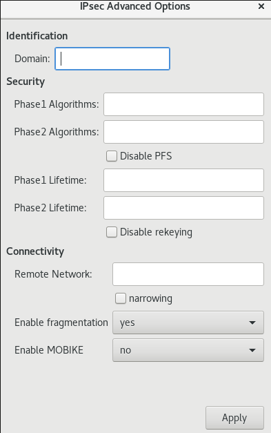 Warning
When configuring an IPsec-based VPN connection using the
gnome-control-centerapplication, theAdvanceddialog displays the configuration, but it does not allow any changes. As a consequence, users cannot change any advanced IPsec options. Use thenm-connection-editorornmclitools instead to perform configuration of the advanced properties.Identification
Domain— If required, enter the Domain Name.Security
-
Phase1 Algorithms— corresponds to theikeLibreswan parameter — enter the algorithms to be used to authenticate and set up an encrypted channel. Phase2 Algorithms— corresponds to theespLibreswan parameter — enter the algorithms to be used for theIPsecnegotiations.Check the
Disable PFSfield to turn off Perfect Forward Secrecy (PFS) to ensure compatibility with old servers that do not support PFS.-
Phase1 Lifetime— corresponds to theikelifetimeLibreswan parameter — how long the key used to encrypt the traffic will be valid. Phase2 Lifetime— corresponds to thesalifetimeLibreswan parameter — how long a particular instance of a connection should last before expiring.Note that the encryption key should be changed from time to time for security reasons.
Remote network— corresponds to therightsubnetLibreswan parameter — the destination private remote network that should be reached through the VPN.Check the
narrowingfield to enable narrowing. Note that it is only effective in IKEv2 negotiation.-
Enable fragmentation— corresponds to thefragmentationLibreswan parameter — whether or not to allow IKE fragmentation. Valid values areyes(default) orno. -
Enable Mobike— corresponds to themobikeLibreswan parameter — whether or not to allow Mobility and Multihoming Protocol (MOBIKE, RFC 4555) to enable a connection to migrate its endpoint without needing to restart the connection from scratch. This is used on mobile devices that switch between wired, wireless, or mobile data connections. The values areno(default) oryes.
-
Select the menu entry:
IPv4 Method
-
Automatic (DHCP)— Choose this option if the network you are connecting to uses aDHCPserver to assign dynamicIPaddresses. -
Link-Local Only— Choose this option if the network you are connecting to does not have aDHCPserver and you do not want to assignIPaddresses manually. Random addresses will be assigned as per RFC 3927 with prefix169.254/16. -
Manual— Choose this option if you want to assignIPaddresses manually. Disable—IPv4is disabled for this connection.DNS
In the
DNSsection, whenAutomaticisON, switch it toOFFto enter the IP address of a DNS server you want to use separating the IPs by comma.Routes
Note that in the
Routessection, whenAutomaticisON, routes from DHCP are used, but you can also add additional static routes. WhenOFF, only static routes are used.-
Address— Enter theIPaddress of a remote network or host. -
Netmask— The netmask or prefix length of theIPaddress entered above. -
Gateway— TheIPaddress of the gateway leading to the remote network or host entered above. Metric— A network cost, a preference value to give to this route. Lower values will be preferred over higher values.Use this connection only for resources on its network
Select this check box to prevent the connection from becoming the default route. Selecting this option means that only traffic specifically destined for routes learned automatically over the connection or entered here manually is routed over the connection.
-
To configure
IPv6settings in aVPNconnection, select the menu entry:IPv6 Method
-
Automatic— Choose this option to useIPv6Stateless Address AutoConfiguration (SLAAC) to create an automatic, stateless configuration based on the hardware address and Router Advertisements (RA). -
Automatic, DHCP only— Choose this option to not use RA, but request information fromDHCPv6directly to create a stateful configuration. -
Link-Local Only— Choose this option if the network you are connecting to does not have aDHCPserver and you do not want to assignIPaddresses manually. Random addresses will be assigned as per RFC 4862 with prefixFE80::0. -
Manual— Choose this option if you want to assignIPaddresses manually. Disable—IPv6is disabled for this connection.Note that
DNS,Routes,Use this connection only for resources on its networkare common toIPv4settings.
-
-
Once you have finished editing the
VPNconnection, click the button to customize the configuration or the button to save it for the existing one. -
Switch the profile to
ONto activate theVPNconnection.
Additional resources
-
nm-settings-libreswan(5)
7.17. Configuring a VPN connection using nm-connection-editor
If you use Red Hat Enterprise Linux with a graphical interface, you can configure a VPN connection in the nm-connection-editor application.
Prerequisites
-
The
NetworkManager-libreswan-gnomepackage is installed. If you configure an Internet Key Exchange version 2 (IKEv2) connection:
- The certificate is imported into the IPsec network security services (NSS) database.
- The nickname of the certificate in the NSS database is known.
Procedure
Open a terminal, and enter:
$ nm-connection-editor- Click the button to add a new connection.
-
Select the
IPsec based VPNconnection type, and click . On the
VPNtab:Enter the host name or IP address of the VPN gateway into the
Gatewayfield, and select an authentication type. Based on the authentication type, you must enter different additional information:-
IKEv2 (Certifiate)authenticates the client by using a certificate, which is more secure. This setting requires the nickname of the certificate in the IPsec NSS database IKEv1 (XAUTH)authenticates the user by using a user name and password (pre-shared key). This setting requires that you enter the following values:- User name
- Password
- Group name
- Secret
-
If the remote server specifies a local identifier for the IKE exchange, enter the exact string in the
Remote IDfield. In the remote server runs Libreswan, this value is set in the server’sleftidparameter.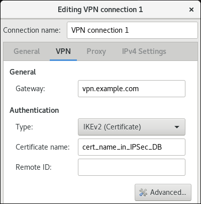
Optional: Configure additional settings by clicking the button. You can configure the following settings:
Identification
-
Domain— If required, enter the domain name.
-
Security
-
Phase1 Algorithmscorresponds to theikeLibreswan parameter. Enter the algorithms to be used to authenticate and set up an encrypted channel. Phase2 Algorithmscorresponds to theespLibreswan parameter. Enter the algorithms to be used for theIPsecnegotiations.Check the
Disable PFSfield to turn off Perfect Forward Secrecy (PFS) to ensure compatibility with old servers that do not support PFS.-
Phase1 Lifetimecorresponds to theikelifetimeLibreswan parameter. This parameter defines how long the key used to encrypt the traffic is valid. -
Phase2 Lifetimecorresponds to thesalifetimeLibreswan parameter. This parameter defines how long a security association is valid.
-
Connectivity
Remote networkcorresponds to therightsubnetLibreswan parameter and defines the destination private remote network that should be reached through the VPN.Check the
narrowingfield to enable narrowing. Note that it is only effective in the IKEv2 negotiation.-
Enable fragmentationcorresponds to thefragmentationLibreswan parameter and defines whether or not to allow IKE fragmentation. Valid values areyes(default) orno. -
Enable Mobikecorresponds to themobikeLibreswan parameter. The parameter defines whether or not to allow Mobility and Multihoming Protocol (MOBIKE) (RFC 4555) to enable a connection to migrate its endpoint without needing to restart the connection from scratch. This is used on mobile devices that switch between wired, wireless or mobile data connections. The values areno(default) oryes.
On the
IPv4 Settingstab, select the IP assignment method and, optionally, set additional static addresses, DNS servers, search domains, and routes.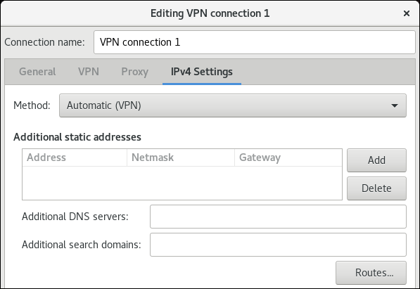
- Save the connection.
-
Close
nm-connection-editor.
When you add a new connection by clicking the button, NetworkManager creates a new configuration file for that connection and then opens the same dialog that is used for editing an existing connection. The difference between these dialogs is that an existing connection profile has a Details menu entry.
Additional resources
-
nm-settings-libreswan(5)man page on your system
7.18. Configuring an IPsec based VPN connection by using nmstatectl
IPsec (Internet Protocol Security) is a security protocol suite, provided by Libreswan, for implementation of VPN. IPsec includes protocols to initiate authentication at the time of connection establishment and manage keys during the data transfer. When an application deploys in a network and communicates by using the IP protocol, IPsec can protect data communication.
To manage an IPsec-based configuration for authenticating VPN connections, you can use the nmstatectl utility. This utility provides command line access to a declarative API for host network management. The following are the authentication types for the host-to-subnet and host-to-host communication modes:
- Host-to-subnet PKI authentication
- Host-to-subnet RSA authentication
- Host-to-subnet PSK authentication
- Host-to-host tunnel mode authentication
- Host-to-host transport mode authentication
7.18.1. Configuring a host-to-subnet IPSec VPN with PKI authentication and tunnel mode by using nmstatectl
If you want to use encryption based on the trusted entity authentication in IPsec, Public Key Infrastructure (PKI) provides secure communication by using cryptographic keys between two hosts. Both communicating hosts generate private and public keys where each host maintains a private key by sharing public key with the trusted entity Certificate Authority (CA). The CA generates a digital certificate after verifying the authenticity. In case of encryption and decryption, the host uses a private key for encryption and public key for decryption.
By using Nmstate, a declarative API for network management, you can configure a PKI authentication-based IPsec connection. After setting the configuration, the Nmstate API ensures that the result matches with the configuration file. If anything fails, nmstate automatically rolls back the changes to avoid an incorrect state of the system.
To establish encrypted communication in host-to-subnet configuration, remote IPsec end provides another IP to host by using parameter dhcp: true. In the case of defining systems for IPsec in nmstate, the left-named system is the local host while the right-named system is the remote host. The following procedure needs to run on both hosts.
Prerequisites
- By using a password, you have generated a PKCS #12 file that stores certificates and cryptographic keys.
Procedure
Install the required packages:
# dnf install nmstate libreswan NetworkManager-libreswanRestart the NetworkManager service:
# systemctl restart NetworkManagerAs
Libreswanwas already installed, remove its old database files and re-create them:# systemctl stop ipsec # rm /etc/ipsec.d/*db # ipsec initnss
Enable and start the
ipsecservice:# systemctl enable --now ipsecImport the PKCS#12 file:
# ipsec import node-example.p12When importing the PKCS#12 file, enter the password that was used to create the file.
Create a YAML file, for example
~/create-pki-authentication.yml, with the following content:--- interfaces: - name: 'example_ipsec_conn1' 1 type: ipsec ipv4: enabled: true dhcp: true libreswan: ipsec-interface: 'yes' 2 left: '192.0.2.250' 3 leftid: '%fromcert' 4 leftcert: 'local-host.example.com' 5 right: '192.0.2.150' 6 rightid: '%fromcert' 7 ikev2: 'insist' 8 ikelifetime: '24h' 9 salifetime: '24h' 10
The YAML file defines the following settings:
- 1
- An IPsec connection name
- 2
- The value
yesmeanslibreswancreates an IPsecxfrmvirtual interfaceipsec<number>and automatically finds the next available number - 3
- A static IPv4 address of public network interface for a local host
- 4
- On a local host, the value of
%fromcertsets the ID to a Distinguished Name (DN) that is fetched from a loaded certificate - 5
- A Distinguished Name (DN) of a local host’s public key
- 6
- A static IPv4 address of public network interface for a remote host
- 7
- On a remote host, the value of
%fromcertsets the ID to a Distinguished Name (DN) that is fetched from a loaded certificate. - 8
insistvalue accepts and receives only the Internet Key Exchange (IKEv2) protocol- 9
- The duration of IKE protocol
- 10
- The duration of IPsec security association (SA)
Apply settings to the system:
# nmstatectl apply ~/create-pki-authentication.yml
Verification
Verify IPsec status:
# ip xfrm statusVerify IPsec policies:
# ip xfrm policy
Additional resources
-
ipsec.conf(5)man page on your system
7.18.2. Configuring a host-to-subnet IPSec VPN with RSA authentication and tunnel mode by using nmstatectl
If you want to use asymmetric cryptography-based key authentication in IPsec, the RSA algorithm provides secure communication by using either of private and public keys for encryption and decryption between two hosts. This method uses a private key for encryption, and a public key for decryption.
By using Nmstate, a declarative API for network management, you can configure RSA-based IPsec authentication. After setting the configuration, the Nmstate API ensures that the result matches with the configuration file. If anything fails, nmstate automatically rolls back the changes to avoid an incorrect state of the system.
To establish encrypted communication in host-to-subnet configuration, remote IPsec end provides another IP to host by using parameter dhcp: true. In the case of defining systems for IPsec in nmstate, the left-named system is the local host while the right-named system is the remote host. The following procedure needs to run on both hosts.
Procedure
Install the required packages:
# dnf install nmstate libreswan NetworkManager-libreswanRestart the NetworkManager service:
# systemctl restart NetworkManagerIf
Libreswanwas already installed, remove its old database files and re-create them:# systemctl stop ipsec # rm /etc/ipsec.d/*db # ipsec initnss
Generate a RSA key pair on each host:
# ipsec newhostkey --outputDisplay the public keys:
# ipsec showhostkey --listThe previous step returned the generated key
ckaid. Use thatckaidwith the following command on left, for example:# ipsec showhostkey --left --ckaid <0sAwEAAesFfVZqFzRA9F>The output of the previous command generated the
leftrsasigkey=line required for the configuration. Do the same on the second host (right):# ipsec showhostkey --right --ckaid <0sAwEAAesFfVZqFzRA9E>Enable the
ipsecservice to automatically start it on boot:# systemctl enable --now ipsecCreate a YAML file, for example
~/create-rsa-authentication.yml, with the following content:--- interfaces: - name: 'example_ipsec_conn1' 1 type: ipsec 2 ipv4: enabled: true dhcp: true libreswan: ipsec-interface: '99' 3 leftrsasigkey: '0sAwEAAesFfVZqFzRA9F' 4 left: '192.0.2.250' 5 leftid: 'local-host-rsa.example.com' 6 right: '192.0.2.150' 7 rightrsasigkey: '0sAwEAAesFfVZqFzRA9E' 8 rightid: 'remote-host-rsa.example.com' 9 ikev2: 'insist' 10
The YAML file defines the following settings:
- 1
- An IPsec connection name
- 2
- An interface name
- 3
- The value
99means thatlibreswancreates an IPsecxfrmvirtual interfaceipsec<number>and automatically finds the next available number - 4
- The RSA public key of a local host
- 5
- A static IPv4 address of public network interface of a local host
- 6
- A Distinguished Name (DN) for a local host
- 7
- The RSA public key of a remote host
- 8
- A static IPv4 address of public network interface of a remote host
- 9
- A Distinguished Name(DN) for a remote host
- 10
insistvalue accepts and receives only the Internet Key Exchange (IKEv2) protocol
Apply the settings to the system:
# nmstatectl apply ~/create-rsa-authentication.yml
Verification
Display the IP settings of the network interface:
# ip addr show example_ipsec_conn1Verify IPsec status:
# ip xfrm statusVerify IPsec policies:
# ip xfrm policy
Additional resources
-
ipsec.conf(5)man page on your system
7.18.3. Configuring a host-to-subnet IPSec VPN with PSK authentication and tunnel mode by using nmstatectl
If you want to use encryption based on mutual authentication in IPsec, the Pre-Shared Key (PSK) method provides secure communication by using a secret key between two hosts. A file stores the secret key and the same key encrypts the data flowing through the tunnel.
By using Nmstate, a declarative API for network management, you can configure PSK-based IPsec authentication. After setting the configuration, the Nmstate API ensures that the result matches with the configuration file. If anything fails, nmstate automatically rolls back the changes to avoid incorrect state of the system.
To establish encrypted communication in host-to-subnet configuration, remote IPsec end provides another IP to host by using parameter dhcp: true. In the case of defining systems for IPsec in nmstate, the left-named system is the local host while the right-named system is the remote host. The following procedure needs to run on both hosts.
As this method uses static strings for authentication and encryption, use it only for testing/development purposes.
Procedure
Install the required packages:
# dnf install nmstate libreswan NetworkManager-libreswanRestart the NetworkManager service:
# systemctl restart NetworkManagerIf
Libreswanwas already installed, remove its old database files and re-create them:# systemctl stop ipsec # rm /etc/ipsec.d/*db # ipsec initnss
Enable the
ipsecservice to automatically start it on boot:# systemctl enable --now ipsecCreate a YAML file, for example
~/create-pks-authentication.yml, with the following content:--- interfaces: - name: 'example_ipsec_conn1' 1 type: ipsec ipv4: enabled: true dhcp: true libreswan: ipsec-interface: 'no' 2 right: '192.0.2.250' 3 rightid: 'remote-host.example.org' 4 left: '192.0.2.150' 5 leftid: 'local-host.example.org' 6 psk: "example_password" ikev2: 'insist' 7
The YAML file defines the following settings:
- 1
- An IPsec connection name
- 2
- Setting
novalue indicates thatlibreswancreates onlyxfrmpolicies, and not a virtualxfrminterface - 3
- A static IPv4 address of public network interface of a remote host
- 4
- A Distinguished Name (DN) for a remote host
- 5
- A static IPv4 address of public network interface of a local host
- 6
- A Distinguished Name (DN) for a local host
- 7
insistvalue accepts and receives only the Internet Key Exchange (IKEv2) protocol
Apply the settings to the system:
# nmstatectl apply ~/create-pks-authentication.yml
Verification
Display the IP settings of network interface:
# ip addr show example_ipsec_conn1Verify IPsec status:
# ip xfrm statusVerify IPsec policies:
# ip xfrm policy
7.18.4. Configuring a host-to-host IPsec VPN with PKI authentication and tunnel mode by using nmstatectl
IPsec (Internet Protocol Security) is a security protocol suite to authenticate and encrypt IP communications within networks and devices. The Libreswan software provides an IPsec implementation for VPNs.
In tunnel mode, the source and destination IP address of communication is encrypted in the IPsec tunnel. External network sniffers can only get left IP and right IP. In general, for tunnel mode, it supports host-to-host, host-to-subnet, and subnet-to-subnet. In this mode, a new IP packet encapsulates an existing packet along with its payload and header. Encapsulation in this mode protects IP data, source, and destination headers over an unsecure network. This mode is useful to transfer data in subnet-to-subnet, remote access connections, and untrusted networks, such as open public Wi-Fi networks. By default, IPsec establishes a secure channel between two sites in tunnel mode. With the following configuration, you can establish a VPN connection as a host-to-host architecture.
By using Nmstate, a declarative API for network management, you can configure an IPsec VPN connection. After setting the configuration, the Nmstate API ensures that the result matches with the configuration file. If anything fails, nmstate automatically rolls back the changes to avoid incorrect state of the system.
In host-to-host configuration, you need to set leftmodecfgclient: no so that it can’t receive network configuration from the server, hence the value no. In the case of defining systems for IPsec in nmstate, the left-named system is the local host while the right-named system is the remote host. The following procedure needs to run on both hosts.
Prerequisites
- By using a password, you have generated a PKCS #12 file that stores certificates and cryptographic keys.
Procedure
Install the required packages:
# dnf install nmstate libreswan NetworkManager-libreswanRestart the NetworkManager service:
# systemctl restart NetworkManagerAs
Libreswanwas already installed, remove its old database files and re-create them:# systemctl stop ipsec # rm /etc/ipsec.d/*db # ipsec initnss
Import the PKCS#12 file:
# ipsec import node-example.p12When importing the PKCS#12 file, enter the password that was used to generate the file.
Enable and start the
ipsecservice:# systemctl enable --now ipsecCreate a YAML file, for example
~/create-p2p-vpn-authentication.yml, with the following content:--- interfaces: - name: 'example_ipsec_conn1' 1 type: ipsec libreswan: left: '192.0.2.250' 2 leftid: 'local-host.example.com' 3 leftcert: 'local-host.example.com' 4 leftmodecfgclient: 'no' 5 right: '192.0.2.150' 6 rightid: 'remote-host.example.com' 7 rightsubnet: '192.0.2.150/32' 8 ikev2: 'insist' 9
The YAML file defines the following settings:
- 1
- An IPsec connection name
- 2
- A static IPv4 address of public network interface for a local host
- 3
- A distinguished Name (DN) of a local host
- 4
- A certificate name installed on a local host
- 5
- The value for not to retrieve client configuration from a remote host
- 6
- A static IPv4 address of public network interface for a remote host
- 7
- A distinguished Name (DN) of a remote host
- 8
- The subnet range of a remote host -
192.0.2.150with32IPv4 addresses - 9
- The value to accept and receive only the Internet Key Exchange (IKEv2) protocol
Apply the settings to the system:
# nmstatectl apply ~/create-p2p-vpn-authentication.yml
Verification
Display the created P2P policy:
# ip xfrm policyVerify IPsec status:
# ip xfrm status
Additional resources
-
ipsec.conf(5)man page on your system
7.18.5. Configuring a host-to-host IPsec VPN with PSK authentication and transport mode by using nmstatectl
IPsec (Internet Protocol Security) is a security protocol suite to authenticate and encrypt IP communications within networks and devices. The Libreswan utility provides IPsec based implementation for VPN.
In transport mode, encryption works only for the payload of an IP packet. Also, a new IPsec header gets appended to the IP packet by keeping the original IP header as it is. Transport mode does not encrypt the source and destination IP of communication but copies them to an external IP header. Hence, encryption protects only IP data across the network. This mode is useful to transfer data in a host-to-host connection of a network. This mode is often used along with the GRE tunnel to save 20 bytes (IP header) of overheads. By default, the IPsec utility uses tunnel mode. To use transfer mode, set type: transport for host-to-host connection data transfer.
By using Nmstate, a declarative API for network management, you can configure an IPsec VPN connection. After setting the configuration, the Nmstate API ensures that the result matches with the configuration file. If anything fails, nmstate automatically rolls back the changes to avoid incorrect state of the system. To override the default tunnel mode, specify transport mode.
In the case of defining systems for IPsec in nmstate, the left-named system is the local host while the right-named system is the remote host. The following procedure needs to run on both hosts.
Prerequisites
- By using a password, you have generated a PKCS #12 file that stores certificates and cryptographic keys.
Procedure
Install the required packages:
# dnf install nmstate libreswan NetworkManager-libreswanRestart the NetworkManager service:
# systemctl restart NetworkManagerAs
Libreswanwas already installed, remove its old database files and re-create them:# systemctl stop ipsec # rm /etc/ipsec.d/*db # ipsec initnss
Import the PKCS#12 file:
# ipsec import node-example.p12When importing the PKCS#12 file, enter the password that was used to create the file.
Enable and start the
ipsecservice:# systemctl enable --now ipsecCreate a YAML file, for example
~/create-p2p-transport-authentication.yml, with the following content:--- interfaces: - name: 'example_ipsec_conn1' 1 type: ipsec libreswan: type: 'transport' 2 ipsec-interface: '99' 3 left: '192.0.2.250' 4 leftid: '%fromcert' 5 leftcert: 'local-host.example.org' 6 right: '192.0.2.150' 7 prefix-length: '32' 8 rightid: '%fromcert' 9 ikev2: 'insist' 10 ikelifetime: '24h' 11 salifetime: '24h' 12
The YAML file defines the following settings:
- 1
- An IPsec connection name
- 2
- An IPsec mode
- 3
- The value
99means thatlibreswancreates an IPsecxfrmvirtual interfaceipsec<number>and automatically finds the next available number - 4
- A static IPv4 address of public network interface for a local host
- 5
- On a local host, the value of
%fromcertsets the ID to a Distinguished Name (DN) which is fetched from a loaded certificate - 6
- A Distinguished Name (DN) of a local host’s public key
- 7
- A static IPv4 address of public network interface for a remote host
- 8
- The subnet mask of a static IPv4 address of a local host
- 9
- On a remote host, the value of
%fromcertsets the ID to a Distinguished Name (DN) which is fetched from a loaded certificate - 10
- The value to accept and receive only the Internet Key Exchange (IKEv2) protocol
- 11
- The duration of IKE protocol
- 12
- The duration of IPsec security association (SA)
Apply the settings to the system:
# nmstatectl apply ~/create-p2p-transport-authentication.yml
Verification
Verify IPsec status:
# ip xfrm statusVerify IPsec policies:
# ip xfrm policy
Additional resources
-
ipsec.conf(5)man page on your system
Chapter 8. Setting up a WireGuard VPN
WireGuard is a high-performance VPN solution that runs in the Linux kernel. It uses modern cryptography and is easier to configure than many other VPN solutions. Additionally, WireGuard’s small codebase reduces the surface for attacks and, therefore, improves security. For authentication and encryption, WireGuard uses keys similar to SSH.
WireGuard is provided as a Technology Preview only. Technology Preview features are not supported with Red Hat production Service Level Agreements (SLAs), might not be functionally complete, and Red Hat does not recommend using them for production. These previews provide early access to upcoming product features, enabling customers to test functionality and provide feedback during the development process.
See Technology Preview Features Support Scope on the Red Hat Customer Portal for information about the support scope for Technology Preview features.
Note that all hosts that participate in a WireGuard VPN are peers. This documentation uses the terms client to describe hosts that establish a connection and server to describe the host with the fixed hostname or IP address that the clients connect to and optionally route all traffic through this server.
To set up a WireGuard VPN, you must complete the following steps. You can perform most steps by using different options:
- Create public and private keys for every host in the VPN.
- Configure the WireGuard server by using nmcli, nmtui, the RHEL web console, nm-connection-editor, or the wg-quick service.
- Configure firewalld on the WireGuard server by using the command line, the RHEL web console, or graphical interface.
- Configure the WireGuard client by using nmcli, nmtui, the RHEL web console, nm-connection-editor, or the wg-quick service.
WireGuard operates on the network layer (layer 3). Therefore, you cannot use DHCP and must assign static IP addresses or IPv6 global addresses to the tunnel devices on both the server and clients.
You can use WireGuard only if the Federal Information Processing Standard (FIPS) mode in RHEL is disabled.
8.1. Protocols and primitives used by WireGuard
WireGuard uses the following protocols and primitives:
- ChaCha20 for symmetric encryption, authenticated with Poly1305, using Authenticated Encryption with Associated Data (AEAD) construction as described in RFC7539
- Curve25519 for Elliptic-curve Diffie–Hellman (ECDH) key exchange
- BLAKE2s for hashing and keyed hashing, as described in RFC7693
- SipHash24 for hash table keys
- HKDF for key derivation, as described in RFC5869
8.2. How WireGuard uses tunnel IP addresses, public keys, and remote endpoints
When WireGuard sends a network packet to a peer:
- WireGuard reads the destination IP from the packet and compares it to the list of allowed IP addresses in the local configuration. If the peer is not found, WireGuard drops the packet.
- If the peer is valid, WireGuard encrypts the packet using the peer’s public key.
- The sending host looks up the most recent Internet IP address of the host and sends the encrypted packet to it.
When WireGuard receives a packet:
- WireGuard decrypts the packet using the private key of the remote host.
- WireGuard reads the internal source address from the packet and looks up whether the IP is configured in the list of allowed IP addresses in the settings for the peer on the local host. If the source IP is on the allowlist, WireGuard accepts the packet. If the IP address is not on the list, WireGuard drops the packet.
The association of public keys and allowed IP addresses is called Cryptokey Routing Table. This means that the list of IP addresses behaves similar to a routing table when sending packets, and as a kind of access control list when receiving packets.
8.3. Using a WireGuard client behind NAT and firewalls
WireGuard uses the UDP protocol and transmits data only when a peer sends packets. Stateful firewalls and network address translation (NAT) on routers track connections to enable a peer behind NAT or a firewall to receive packets.
To keep the connection active, WireGuard supports persistent keepalives. This means you can set an interval at which WireGuard sends keepalive packets. By default, the persistent keep-alive feature is disabled to reduce network traffic. Enable this feature on the client if you use the client in a network with NAT or if a firewall closes the connection after some time of inactivity.
Note that you cannot configure keepalive packets in WireGuard connections by using the RHEL web console. To configure this feature, edit the connection profile by using the nmcli utility.
8.4. Creating private and public keys to be used in WireGuard connections
WireGuard uses base64-encoded private and public keys to authenticate hosts to each other. Therefore, you must create the keys on each host that participates in the WireGuard VPN.
For secure connections, create different keys for each host, and ensure that you only share the public key with the remote WireGuard host. Do not use the example keys used in this documentation.
If you plan to use the RHEL web console to create a WireGuard VPN connection, you can, alternatively, generate the public and private key pairs in the web console.
Procedure
Install the
wireguard-toolspackage:# dnf install wireguard-toolsCreate a private key and a corresponding public key for the host:
# wg genkey | tee /etc/wireguard/$HOSTNAME.private.key | wg pubkey > /etc/wireguard/$HOSTNAME.public.keyYou will need the content of the key files, but not the files themselves. However, Red Hat recommends keeping the files in case that you need to remember the keys in future.
Set secure permissions on the key files:
# chmod 600 /etc/wireguard/$HOSTNAME.private.key /etc/wireguard/$HOSTNAME.public.keyDisplay the private key:
# cat /etc/wireguard/$HOSTNAME.private.key
YFAnE0psgIdiAF7XR4abxiwVRnlMfeltxu10s/c4JXg=
You will need the private key to configure the WireGuard connection on the local host. Do not share the private key.
Display the public key:
# cat /etc/wireguard/$HOSTNAME.public.key
UtjqCJ57DeAscYKRfp7cFGiQqdONRn69u249Fa4O6BE=
You will need the public key to configure the WireGuard connection on the remote host.
Additional resources
-
wg(8)man page on your system
8.5. Configuring a WireGuard server by using nmcli
You can configure the WireGuard server by creating a connection profile in NetworkManager. Use this method to let NetworkManager manage the WireGuard connection.
This procedure assumes the following settings:
Server:
-
Private key:
YFAnE0psgIdiAF7XR4abxiwVRnlMfeltxu10s/c4JXg= -
Tunnel IPv4 address:
192.0.2.1/24 -
Tunnel IPv6 address:
2001:db8:1::1/32
-
Private key:
Client:
-
Public key:
bnwfQcC8/g2i4vvEqcRUM2e6Hi3Nskk6G9t4r26nFVM= -
Tunnel IPv4 address:
192.0.2.2/24 -
Tunnel IPv6 address:
2001:db8:1::2/32
-
Public key:
Prerequisites
- You have generated the public and private key for both the server and client.
You know the following information:
- The private key of the server
- The static tunnel IP addresses and subnet masks of the client
- The public key of the client
- The static tunnel IP addresses and subnet masks of the server
Procedure
Add a NetworkManager WireGuard connection profile:
# nmcli connection add type wireguard con-name server-wg0 ifname wg0 autoconnect noThis command creates a profile named
server-wg0and assigns the virtual interfacewg0to it. To prevent the connection from starting automatically after you add it without finalizing the configuration, disable theautoconnectparameter.Set the tunnel IPv4 address and subnet mask of the server:
# nmcli connection modify server-wg0 ipv4.method manual ipv4.addresses 192.0.2.1/24Set the tunnel IPv6 address and subnet mask of the server:
# nmcli connection modify server-wg0 ipv6.method manual ipv6.addresses 2001:db8:1::1/32Add the server’s private key to the connection profile:
# nmcli connection modify server-wg0 wireguard.private-key "YFAnE0psgIdiAF7XR4abxiwVRnlMfeltxu10s/c4JXg="Set the port for incoming WireGuard connections:
# nmcli connection modify server-wg0 wireguard.listen-port 51820Always set a fixed port number on hosts that receive incoming WireGuard connections. If you do not set a port, WireGuard uses a random free port each time you activate the
wg0interface.Add peer configurations for each client that you want to allow to communicate with this server. You must add these settings manually, because the
nmcliutility does not support setting the corresponding connection properties.Edit the
/etc/NetworkManager/system-connections/server-wg0.nmconnectionfile, and append:[wireguard-peer.bnwfQcC8/g2i4vvEqcRUM2e6Hi3Nskk6G9t4r26nFVM=] allowed-ips=192.0.2.2;2001:db8:1::2;
-
The
[wireguard-peer.<public_key_of_the_client>]entry defines the peer section of the client, and the section name contains the public key of the client. The
allowed-ipsparameter sets the tunnel IP addresses of the client that are allowed to send data to this server.Add a section for each client.
-
The
Reload the
server-wg0connection profile:# nmcli connection load /etc/NetworkManager/system-connections/server-wg0.nmconnection
Optional: Configure the connection to start automatically, enter:
# nmcli connection modify server-wg0 autoconnect yesReactivate the
server-wg0connection:# nmcli connection up server-wg0
Verification
Display the interface configuration of the
wg0device:# wg show wg0 interface: wg0 public key: UtjqCJ57DeAscYKRfp7cFGiQqdONRn69u249Fa4O6BE= private key: (hidden) listening port: 51820 peer: bnwfQcC8/g2i4vvEqcRUM2e6Hi3Nskk6G9t4r26nFVM= allowed ips: 192.0.2.2/32, 2001:db8:1::2/128To display the private key in the output, use the
WG_HIDE_KEYS=never wg show wg0command.Display the IP configuration of the
wg0device:# ip address show wg0 20: wg0: <POINTOPOINT,NOARP,UP,LOWER_UP> mtu 1420 qdisc noqueue state UNKNOWN group default qlen 1000 link/none inet 192.0.2.1/24 brd 192.0.2.255 scope global noprefixroute wg0 valid_lft forever preferred_lft forever inet6 2001:db8:1::1/32 scope global noprefixroute valid_lft forever preferred_lft forever inet6 fe80::3ef:8863:1ce2:844/64 scope link noprefixroute valid_lft forever preferred_lft forever
Additional resources
-
wg(8)man page on your system -
WireGuard settingsection in thenm-settings(5)man page on your system
8.6. Configuring a WireGuard server by using nmtui
You can configure the WireGuard server by creating a connection profile in NetworkManager. Use this method to let NetworkManager manage the WireGuard connection.
This procedure assumes the following settings:
Server:
-
Private key:
YFAnE0psgIdiAF7XR4abxiwVRnlMfeltxu10s/c4JXg= -
Tunnel IPv4 address:
192.0.2.1/24 -
Tunnel IPv6 address:
2001:db8:1::1/32
-
Private key:
Client:
-
Public key:
bnwfQcC8/g2i4vvEqcRUM2e6Hi3Nskk6G9t4r26nFVM= -
Tunnel IPv4 address:
192.0.2.2/24 -
Tunnel IPv6 address:
2001:db8:1::2/32
-
Public key:
Prerequisites
- You have generated the public and private key for both the server and client.
You know the following information:
- The private key of the server
- The static tunnel IP addresses and subnet masks of the client
- The public key of the client
- The static tunnel IP addresses and subnet masks of the server
-
You installed the
NetworkManager-tuipackage.
Procedure
Start the
nmtuiapplication:# nmtui- Select Edit a connection, and press Enter.
- Select , and press Enter.
- Select the WireGuard connection type in the list, and press Enter.
In the Edit connection window:
-
Enter the name of the connection and the virtual interface, such as
wg0, that NetworkManager should assign to the connection. - Enter the private key of the server.
Set the listen port number, such as
51820, for incoming WireGuard connections.Always set a fixed port number on hosts that receive incoming WireGuard connections. If you do not set a port, WireGuard uses a random free port each time you activate the interface.

Click next to the Peers pane:
- Enter the public key of the client.
- Set the Allowed IPs field to the tunnel IP addresses of the client that are allowed to send data to this server.
Select , and press Enter.

Select next to *IPv4 Configuration, and press Enter.
- Select the IPv4 configuration method Manual.
- Enter the tunnel IPv4 address and the subnet mask. Leave the Gateway field empty.
Select next to IPv6 Configuration, and press Enter.
- Select the IPv6 configuration method Manual.
-
Enter the tunnel IPv6 address and the subnet mask. Leave the
Gatewayfield empty.
Select , and press Enter
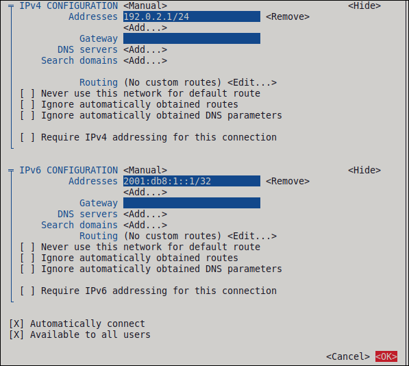
-
Enter the name of the connection and the virtual interface, such as
- In the window with the list of connections, select , and press Enter.
- In the NetworkManager TUI main window, select , and press Enter.
Verification
Display the interface configuration of the
wg0device:# wg show wg0 interface: wg0 public key: UtjqCJ57DeAscYKRfp7cFGiQqdONRn69u249Fa4O6BE= private key: (hidden) listening port: 51820 peer: bnwfQcC8/g2i4vvEqcRUM2e6Hi3Nskk6G9t4r26nFVM= allowed ips: 192.0.2.2/32, 2001:db8:1::2/128To display the private key in the output, use the
WG_HIDE_KEYS=never wg show wg0command.Display the IP configuration of the
wg0device:# ip address show wg0 20: wg0: <POINTOPOINT,NOARP,UP,LOWER_UP> mtu 1420 qdisc noqueue state UNKNOWN group default qlen 1000 link/none inet 192.0.2.1/24 brd 192.0.2.255 scope global noprefixroute wg0 valid_lft forever preferred_lft forever inet6 _2001:db8:1::1/32 scope global noprefixroute valid_lft forever preferred_lft forever inet6 fe80::3ef:8863:1ce2:844/64 scope link noprefixroute valid_lft forever preferred_lft forever
Additional resources
-
wg(8)man page on your system
8.7. Configuring a WireGuard server by using the RHEL web console
You can configure a WireGuard server by using the browser-based RHEL web console. Use this method to let NetworkManager manage the WireGuard connection.
Prerequisites
- You are logged in to the RHEL web console.
You know the following information:
- The static tunnel IP addresses and subnet masks of both the server and client
- The public key of the client
Procedure
- Select the Networking tab in the navigation on the left side of the screen.
- Click Add VPN in the Interfaces section.
-
If the
wireguard-toolsandsystemd-resolvedpackages are not already installed, the web console displays a corresponding notification. Click Install to install these packages. - Enter the name of the WireGuard device that you want to create.
Configure the key pair of this host:
If you want use the keys that the web console has created:
- Keep the pre-selected Generated option in the Private key area.
- Note the Public key value. You require this information when you configure the client.
If you want to use an existing private key:
- Select Paste existing key in the Private key area.
- Paste the private key into the text field. The web console automatically calculates the corresponding public key.
Set a listen port number, such as
51820, for incoming WireGuard connections.Always set a fixed port number on hosts that receive incoming WireGuard connections. If you do not set a port, WireGuard uses a random free port each time you activate the interface.
Set the tunnel IPv4 address and subnet mask of the server.
To also set an IPv6 address, you must edit the connection after you have created it.
Add peer configurations for each client that you want to allow to communicate with this server:
- Click Add peer.
- Enter the public key of the client.
- Leave the Endpoint field empty.
- Set the Allowed IPs field to the tunnel IP addresses of the clients that are allowed to send data to this server.
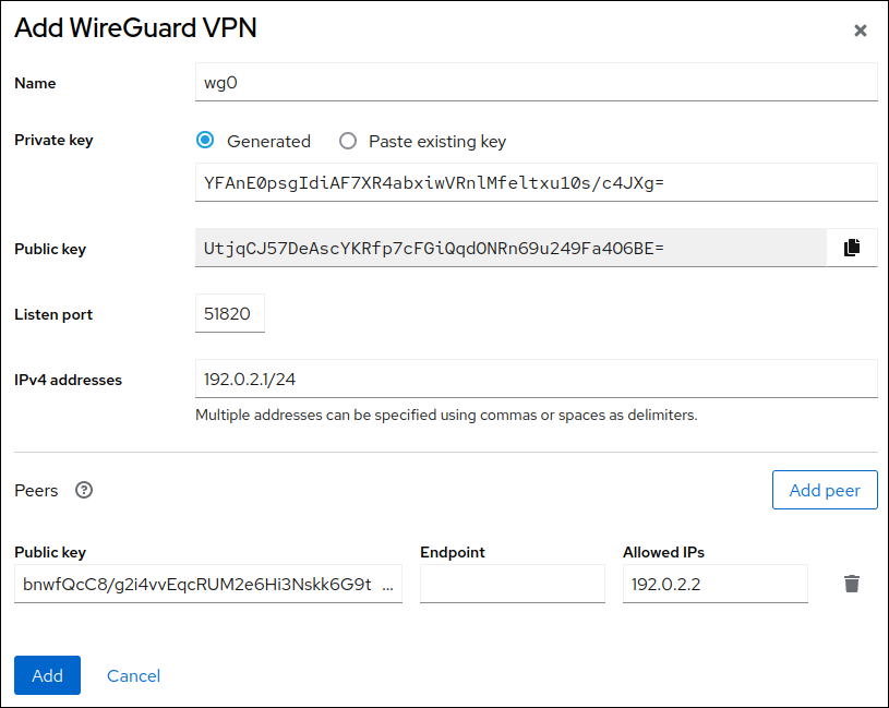
- Click Add to create the WireGuard connection.
If you want to also set a tunnel IPv6 address:
- Click on the WireGuard connection’s name in the Interfaces section.
- Click edit next to IPv6.
-
Set the Addresses field to
Manual, and enter the tunnel IPv6 address and prefix of the server. - Click Save.
Verification
Display the interface configuration of the
wg0device:# wg show wg0 interface: wg0 public key: UtjqCJ57DeAscYKRfp7cFGiQqdONRn69u249Fa4O6BE= private key: (hidden) listening port: 51820 peer: bnwfQcC8/g2i4vvEqcRUM2e6Hi3Nskk6G9t4r26nFVM= allowed ips: 192.0.2.2/32, 2001:db8:1::2/128To display the private key in the output, use the
WG_HIDE_KEYS=never wg show wg0command.Display the IP configuration of the
wg0device:# ip address show wg0 20: wg0: <POINTOPOINT,NOARP,UP,LOWERUP> mtu 1420 qdisc noqueue state UNKNOWN group default qlen 1000 link/none inet 192.0.2.1/24 brd 192.0.2.255 scope global noprefixroute wg0 valid_lft forever preferred_lft forever inet6 2001:db8:1::1/32 scope global noprefixroute valid_lft forever preferred_lft forever inet6 fe80::3ef:8863:1ce2:844/64 scope link noprefixroute valid_lft forever preferred_lft forever
8.8. Configuring a WireGuard server by using nm-connection-editor
You can configure the WireGuard server by creating a connection profile in NetworkManager. Use this method to let NetworkManager manage the WireGuard connection.
Prerequisites
- You have generated the public and private key for both the server and client.
You know the following information:
- The private key of the server
- The static tunnel IP addresses and subnet masks of the client
- The public key of the client
- The static tunnel IP addresses and subnet masks of the server
Procedure
Open a terminal, and enter:
# nm-connection-editor- Add a new connection by clicking the button.
-
Select the
WireGuardconnection type, and click . - Optional: Update the connection name.
-
On the
Generaltab, selectConnect automatically with priority. Optionally, set a priority value. On the
WireGuardtab:-
Enter the name of the virtual interface, such as
wg0, that NetworkManager should assign to the connection. - Enter the private key of the server.
Set the listen port number, such as
51820, for incoming WireGuard connections.Always set a fixed port number on hosts that receive incoming WireGuard connections. If you do not set a port, WireGuard uses a random free port each time you activate the interface.
Click to add peers:
- Enter the public key of the client.
-
Set the
Allowed IPsfield to the tunnel IP addresses of the client that are allowed to send data to this server. - Click .
-
Enter the name of the virtual interface, such as
On the
IPv4 Settingstab:-
Select
Manualin theMethodlist. -
Click to enter the tunnel IPv4 address and the subnet mask. Leave the
Gatewayfield empty.
-
Select
On the
IPv6 Settingstab:-
Select
Manualin theMethodlist. -
Click to enter the tunnel IPv6 address and the subnet mask. Leave the
Gatewayfield empty.
-
Select
- Click to store the connection profile.
Verification
Display the interface configuration of the
wg0device:# wg show wg0 interface: wg0 public key: UtjqCJ57DeAscYKRfp7cFGiQqdONRn69u249Fa4O6BE= private key: (hidden) listening port: 51820 peer: bnwfQcC8/g2i4vvEqcRUM2e6Hi3Nskk6G9t4r26nFVM= allowed ips: 192.0.2.2/32, 2001:db8:1::2/128
To display the private key in the output, use the
WG_HIDE_KEYS=never wg show wg0command.Display the IP configuration of the
wg0device:# ip address show wg0 20: wg0: <POINTOPOINT,NOARP,UP,LOWER_UP> mtu 1420 qdisc noqueue state UNKNOWN group default qlen 1000 link/none inet 192.0.2.1/24 brd 192.0.2.255 scope global noprefixroute wg0 valid_lft forever preferred_lft forever inet6 2001:db8:1::1/32 scope global noprefixroute valid_lft forever preferred_lft forever inet6 fe80::3ef:8863:1ce2:844/64 scope link noprefixroute valid_lft forever preferred_lft forever
Additional resources
-
wg(8)man page on your system
8.9. Configuring a WireGuard server by using the wg-quick service
You can configure the WireGuard server by creating a configuration file in the /etc/wireguard/ directory. Use this method to configure the service independently from NetworkManager.
This procedure assumes the following settings:
Server:
-
Private key:
YFAnE0psgIdiAF7XR4abxiwVRnlMfeltxu10s/c4JXg= -
Tunnel IPv4 address:
192.0.2.1/24 -
Tunnel IPv6 address:
2001:db8:1::1/32
-
Private key:
Client:
-
Public key:
bnwfQcC8/g2i4vvEqcRUM2e6Hi3Nskk6G9t4r26nFVM= -
Tunnel IPv4 address:
192.0.2.2/24 -
Tunnel IPv6 address:
2001:db8:1::2/32
-
Public key:
Prerequisites
- You have generated the public and private key for both the server and client.
You know the following information:
- The private key of the server
- The static tunnel IP addresses and subnet masks of the client
- The public key of the client
- The static tunnel IP addresses and subnet masks of the server
Procedure
Install the
wireguard-toolspackage:# dnf install wireguard-toolsCreate the
/etc/wireguard/wg0.conffile with the following content:[Interface] Address = 192.0.2.1/24, 2001:db8:1::1/32 ListenPort = 51820 PrivateKey = YFAnE0psgIdiAF7XR4abxiwVRnlMfeltxu10s/c4JXg= [Peer] PublicKey = bnwfQcC8/g2i4vvEqcRUM2e6Hi3Nskk6G9t4r26nFVM= AllowedIPs = 192.0.2.2, 2001:db8:1::2
The
[Interface]section describes the WireGuard settings of the interface on the server:-
Address: A comma-separated list of the server’s tunnel IP addresses. -
PrivateKey: The private key of the server. ListenPort: The port on which WireGuard listens for incoming UDP connections.Always set a fixed port number on hosts that receive incoming WireGuard connections. If you do not set a port, WireGuard uses a random free port each time you activate the
wg0interface.
-
Each
[Peer]section describes the settings of one client:-
PublicKey: The public key of the client. -
AllowedIPs: The tunnel IP addresses of the client that are allowed to send data to this server.
-
Enable and start the WireGuard connection:
# systemctl enable --now wg-quick@wg0The systemd instance name must match the name of the configuration file in the
/etc/wireguard/directory without the.confsuffix. The service also uses this name for the virtual network interface.
Verification
Display the interface configuration of the
wg0device:# wg show wg0 interface: wg0 public key: UtjqCJ57DeAscYKRfp7cFGiQqdONRn69u249Fa4O6BE= private key: (hidden) listening port: 51820 peer: bnwfQcC8/g2i4vvEqcRUM2e6Hi3Nskk6G9t4r26nFVM= allowed ips: 192.0.2.2/32, 2001:db8:1::2/128To display the private key in the output, use the
WG_HIDE_KEYS=never wg show wg0command.Display the IP configuration of the
wg0device:# ip address show wg0 20: wg0: <POINTOPOINT,NOARP,UP,LOWER_UP> mtu 1420 qdisc noqueue state UNKNOWN group default qlen 1000 link/none inet 192.0.2.1/24 scope global wg0 valid_lft forever preferred_lft forever inet6 2001:db8:1::1/32 scope global valid_lft forever preferred_lft forever
Additional resources
-
wg(8)andwg-quick(8)man pages on your system
8.10. Configuring firewalld on a WireGuard server by using the command line
You must configure the firewalld service on the WireGuard server to allow incoming connections from clients. Additionally, if clients should be able to use the WireGuard server as the default gateway and route all traffic through the tunnel, you must enable masquerading.
Procedure
Open the WireGuard port for incoming connections in the
firewalldservice:# firewall-cmd --permanent --add-port=51820/udp --zone=publicIf clients should route all traffic through the tunnel and use the WireGuard server as the default gateway, enable masquerading for the
publiczone:# firewall-cmd --permanent --zone=public --add-masqueradeReload the
firewalldrules.# firewall-cmd --reload
Verification
Display the configuration of the
publiczone:# firewall-cmd --list-all public (active) ... ports: 51820/udp masquerade: yes ...
Additional resources
-
firewall-cmd(1)man page on your system
8.11. Configuring firewalld on a WireGuard server by using the RHEL web console
You must configure the firewalld service on the WireGuard server to allow incoming connections from clients. Additionally, if clients should be able to use the WireGuard server as the default gateway and route all traffic through the tunnel, you must enable masquerading.
Prerequisites
- You are logged in to the RHEL web console.
Procedure
- Select the Networking tab in the navigation on the left side of the screen.
- Click Edit rules and zones in the Firewall section.
-
Enter
wireguardinto the Filter services field. Select the
wireguardentry from the list.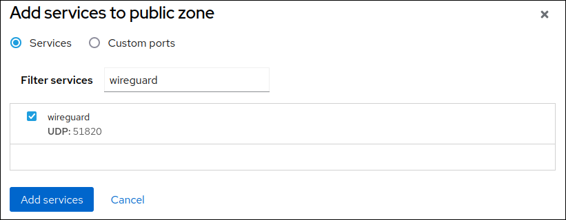
- Click Add services.
If clients should route all traffic through the tunnel and use the WireGuard server as the default gateway, enable masquerading for the
publiczone:# firewall-cmd --permanent --zone=public --add-masquerade # firewall-cmd --reload
Note that you cannot enable masquerading in
firewalldzones in the web console.
Verification
- Select the Networking tab in the navigation on the left side of the screen.
- Click Edit rules and zones in the Firewall section.
-
The list contains an entry for the
wireguardservice and displays the UDP port that you configured in the WireGuard connection profile. To verify that masquerading is enabled in the
firewalldpubliczone, enter:# firewall-cmd --list-all --zone=public public (active) ... ports: 51820/udp masquerade: yes ...
8.12. Configuring firewalld on a WireGuard server by using the graphical interface
You must configure the firewalld service on the WireGuard server to allow incoming connections from clients. Additionally, if clients should be able to use the WireGuard server as the default gateway and route all traffic through the tunnel, you must enable masquerading.
Procedure
-
Press the Super key, enter
firewall, and select the Firewall application from the results. -
Select
Permanentin the Configuration list. -
Select the
publiczone. Allow incoming connections to the WireGuard port:
- On the Ports tab, click .
- Enter the port number you set for incoming WireGuard connections:
-
Select
udpfrom theProtocollist. - Click .
If clients should route all traffic through the tunnel and use the WireGuard server as the default gateway:
- Navigate to the Masquerading tab of the public zone.
-
Select
Masquerade zone.
- Select → .
Verification
Display the configuration of the
publiczone:# firewall-cmd --list-all public (active) ... ports: 51820/udp masquerade: yes ...
8.13. Configuring a WireGuard client by using nmcli
You can configure a WireGuard client by creating a connection profile in NetworkManager. Use this method to let NetworkManager manage the WireGuard connection.
This procedure assumes the following settings:
Client:
-
Private key:
aPUcp5vHz8yMLrzk8SsDyYnV33IhE/k20e52iKJFV0A= -
Tunnel IPv4 address:
192.0.2.2/24 -
Tunnel IPv6 address:
2001:db8:1::2/32
-
Private key:
Server:
-
Public key:
UtjqCJ57DeAscYKRfp7cFGiQqdONRn69u249Fa4O6BE= -
Tunnel IPv4 address:
192.0.2.1/24 -
Tunnel IPv6 address:
2001:db8:1::1/32
-
Public key:
Prerequisites
- You have generated the public and private key for both the server and client.
You know the following information:
- The private key of the client
- The static tunnel IP addresses and subnet masks of the client
- The public key of the server
- The static tunnel IP addresses and subnet masks of the server
Procedure
Add a NetworkManager WireGuard connection profile:
# nmcli connection add type wireguard con-name client-wg0 ifname wg0 autoconnect noThis command creates a profile named
client-wg0and assigns the virtual interfacewg0to it. To prevent the connection from starting automatically after you add it without finalizing the configuration, disable theautoconnectparameter.Optional: Configure NetworkManager so that it does not automatically start the
client-wgconnection:# nmcli connection modify client-wg0 autoconnect noSet the tunnel IPv4 address and subnet mask of the client:
# nmcli connection modify client-wg0 ipv4.method manual ipv4.addresses 192.0.2.2/24Set the tunnel IPv6 address and subnet mask of the client:
# nmcli connection modify client-wg0 ipv6.method manual ipv6.addresses 2001:db8:1::2/32If you want to route all traffic through the tunnel, set the tunnel IP addresses of the server as the default gateway:
# nmcli connection modify client-wg0 ipv4.gateway 192.0.2.1 ipv6.gateway 2001:db8:1::1Routing all traffic through the tunnel requires that you set, in a later step, the
allowed-ipson the this client to0.0.0.0/0;::/0.Note that routing all traffic through the tunnel can impact the connectivity to other hosts based on the server routing and firewall configuration.
Add the client’s private key to the connection profile:
# nmcli connection modify client-wg0 wireguard.private-key "aPUcp5vHz8yMLrzk8SsDyYnV33IhE/k20e52iKJFV0A="Add peer configurations for each server that you want to allow to communicate with this client. You must add these settings manually, because the
nmcliutility does not support setting the corresponding connection properties.Edit the
/etc/NetworkManager/system-connections/client-wg0.nmconnectionfile, and append:[wireguard-peer.UtjqCJ57DeAscYKRfp7cFGiQqdONRn69u249Fa4O6BE=] endpoint=server.example.com:51820 allowed-ips=192.0.2.1;2001:db8:1::1; persistent-keepalive=20
-
The
[wireguard-peer.<public_key_of_the_server>]entry defines the peer section of the server, and the section name has the public key of the server. -
The
endpointparameter sets the hostname or IP address and the port of the server. The client uses this information to establish the connection. The
allowed-ipsparameter sets a list of IP addresses that can send data to this client. For example, set the parameter to:- The tunnel IP addresses of the server to allow only the server to communicate with this client. The value in the example above configures this scenario.
-
0.0.0.0/0;::/0;to allow any remote IPv4 and IPv6 address to communicate with this client. Use this setting to route all traffic through the tunnel and use the WireGuard server as default gateway.
-
The optional
persistent-keepaliveparameter defines an interval in seconds in which WireGuard sends a keepalive packet to the server. Set this parameter if you use the client in a network with network address translation (NAT) or if a firewall closes the UDP connection after some time of inactivity.
-
The
Reload the
client-wg0connection profile:# nmcli connection load /etc/NetworkManager/system-connections/client-wg0.nmconnection
Reactivate the
client-wg0connection:# nmcli connection up client-wg0
Verification
Ping the IP addresses of the server:
# ping 192.0.2.1 # ping6 2001:db8:1::1
Display the interface configuration of the
wg0device:# wg show wg0 interface: wg0 public key: bnwfQcC8/g2i4vvEqcRUM2e6Hi3Nskk6G9t4r26nFVM= private key: (hidden) listening port: 51820 peer: UtjqCJ57DeAscYKRfp7cFGiQqdONRn69u249Fa4O6BE= endpoint: server.example.com:51820 allowed ips: 192.0.2.1/32, 2001:db8:1::1/128 latest handshake: 1 minute, 41 seconds ago transfer: 824 B received, 1.01 KiB sent persistent keepalive: every 20 secondsTo display the private key in the output, use the
WG_HIDE_KEYS=never wg show wg0command.Note that the output has only the
latest handshakeandtransferentries if you have already sent traffic through the VPN tunnel.Display the IP configuration of the
wg0device:# ip address show wg0 10: wg0: <POINTOPOINT,NOARP,UP,LOWER_UP> mtu 1420 qdisc noqueue state UNKNOWN group default qlen 1000 link/none inet 192.0.2.2/24 brd 192.0.2.255 scope global noprefixroute wg0 valid_lft forever preferred_lft forever inet6 2001:db8:1::2/32 scope global noprefixroute valid_lft forever preferred_lft forever inet6 fe80::73d9:6f51:ea6f:863e/64 scope link noprefixroute valid_lft forever preferred_lft forever
Additional resources
-
wg(8)man page on your system -
WireGuard settingsection in thenm-settings(5)man page on your system
8.14. Configuring a WireGuard client by using nmtui
You can configure a WireGuard client by creating a connection profile in NetworkManager. Use this method to let NetworkManager manage the WireGuard connection.
This procedure assumes the following settings:
Client:
-
Private key:
aPUcp5vHz8yMLrzk8SsDyYnV33IhE/k20e52iKJFV0A= -
Tunnel IPv4 address:
192.0.2.2/24 -
Tunnel IPv6 address:
2001:db8:1::2/32
-
Private key:
Server:
-
Public key:
UtjqCJ57DeAscYKRfp7cFGiQqdONRn69u249Fa4O6BE= -
Tunnel IPv4 address:
192.0.2.1/24 -
Tunnel IPv6 address:
2001:db8:1::1/32
-
Public key:
Prerequisites
- You have generated the public and private key for both the server and client.
You know the following information:
- The private key of the client
- The static tunnel IP addresses and subnet masks of the client
- The public key of the server
- The static tunnel IP addresses and subnet masks of the server
-
You installed the
NetworkManager-tuipackage
Procedure
Start the
nmtuiapplication:# nmtui- Select Edit a connection, and press Enter.
- Select , and press Enter.
- Select the WireGuard connection type in the list, and press Enter.
In the Edit connection window:
-
Enter the name of the connection and the virtual interface, such as
wg0, that NetworkManager should assign to the connection. Enter the private key of the client.
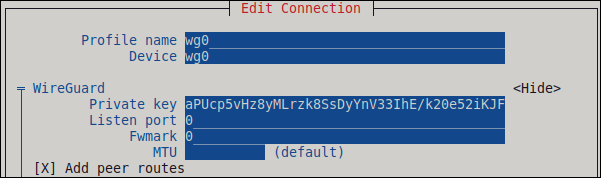
Click next to the Peers pane:
- Enter the public key of the server.
Set the Allowed IPs field. For example, set it to:
- The tunnel IP addresses of the server to allow only the server to communicate with this client.
-
0.0.0.0/0,::/0to allow any remote IPv4 and IPv6 address to communicate with this client. Use this setting to route all traffic through the tunnel and use the WireGuard server as default gateway.
-
Enter the host name or IP address and port of the WireGuard server into the Endpoint field. Use the following format:
<hostname_or_IP>:<port_number> - Optional: If you use the client in a network with network address translation (NAT) or if a firewall closes the UDP connection after some time of inactivity, set a persistent keep alive interval in seconds. In this interval, the client sends a keepalive packet to the server.
Select , and press Enter.
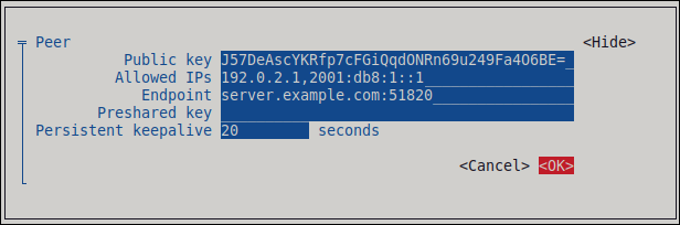
Select next to IPv4 Configuration, and press Enter.
- Select the IPv4 configuration method Manual.
- Enter the tunnel IPv4 address and the subnet mask. Leave the Gateway field empty.
Select next to IPv6 Configuration, and press Enter.
- Select the IPv6 configuration method Manual.
- Enter the tunnel IPv6 address and the subnet mask. Leave the Gateway field empty.
- Optional: Select Automatically connect.
Select , and press Enter
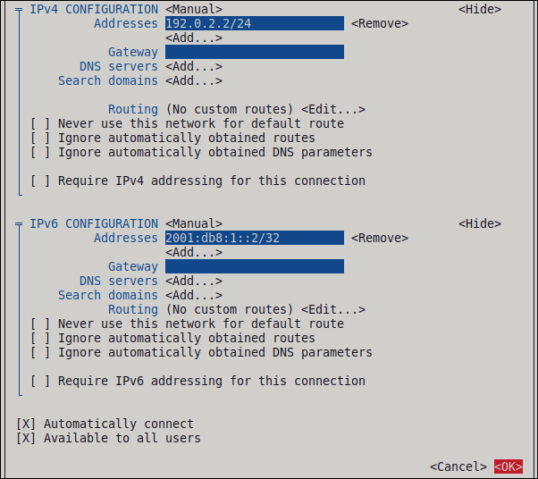
-
Enter the name of the connection and the virtual interface, such as
- In the window with the list of connections, select , and press Enter.
- In the NetworkManager TUI main window, select , and press Enter.
Verification
Ping the IP addresses of the server:
# ping 192.0.2.1 # ping6 2001:db8:1::1
Display the interface configuration of the
wg0device:# wg show wg0 interface: wg0 public key: bnwfQcC8/g2i4vvEqcRUM2e6Hi3Nskk6G9t4r26nFVM= private key: (hidden) listening port: 51820 peer: UtjqCJ57DeAscYKRfp7cFGiQqdONRn69u249Fa4O6BE= endpoint: server.example.com:51820_ allowed ips: 192.0.2.1/32, 2001:db8:1::1/128 latest handshake: 1 minute, 41 seconds ago transfer: 824 B received, 1.01 KiB sent persistent keepalive: every 20 secondsTo display the private key in the output, use the
WG_HIDE_KEYS=never wg show wg0command.Note that the output contains only the
latest handshakeandtransferentries if you have already sent traffic through the VPN tunnel.Display the IP configuration of the
wg0device:# ip address show wg0 10: wg0: <POINTOPOINT,NOARP,UP,LOWER_UP> mtu 1420 qdisc noqueue state UNKNOWN group default qlen 1000 link/none inet 192.0.2.2/24 brd 192.0.2.255 scope global noprefixroute wg0 valid_lft forever preferred_lft forever inet6 2001:db8:1::2/32 scope global noprefixroute valid_lft forever preferred_lft forever inet6 fe80::73d9:6f51:ea6f:863e/64 scope link noprefixroute valid_lft forever preferred_lft forever
Additional resources
-
wg(8)man page on your system
8.15. Configuring a WireGuard client by using the RHEL web console
You can configure a WireGuard client by using the browser-based RHEL web console. Use this method to let NetworkManager manage the WireGuard connection.
Prerequisites
- You are logged in to the RHEL web console.
You know the following information:
- The static tunnel IP addresses and subnet masks of both the server and client
- The public key of the server
Procedure
- Select the Networking tab in the navigation on the left side of the screen.
- Click Add VPN in the Interfaces section.
-
If the
wireguard-toolsandsystemd-resolvedpackages are not already installed, the web console displays a corresponding notification. Click Install to install these packages. - Enter the name of the WireGuard device that you want to create.
Configure the key pair of this host:
If you want use the keys that the web console has created:
- Keep the pre-selected Generated option in the Private key area.
- Note the Public key value. You require this information when you configure the client.
If you want to use an existing private key:
- Select Paste existing key in the Private key area.
- Paste the private key into the text field. The web console automatically calculates the corresponding public key.
-
Preserve the
0value in the Listen port field. Set the tunnel IPv4 address and subnet mask of the client.
To also set an IPv6 address, you must edit the connection after you have created it.
Add a peer configuration for the server that you want to allow to communicate with this client:
- Click Add peer.
- Enter the public key of the server.
-
Set the Endpoint field to the hostname or IP address and the port of the server, for example
server.example.com:51820. The client uses this information to establish the connection. Set the Allowed IPs field to the tunnel IP addresses of the clients that are allowed to send data to this server. For example, set the field to one of the following:
- The tunnel IP addresses of the server to allow only the server to communicate with this client. The value in the screen capture below configures this scenario.
-
0.0.0.0/0to allow any remote IPv4 address to communicate with this client. Use this setting to route all traffic through the tunnel and use the WireGuard server as default gateway.
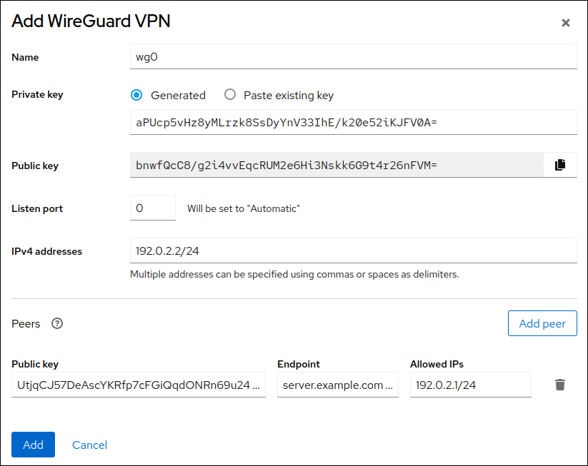
- Click Add to create the WireGuard connection.
If you want to also set a tunnel IPv6 address:
- Click on the WireGuard connection’s name in the Interfaces section.
- Click Edit next to IPv6.
-
Set the Addresses field to
Manual, and enter the tunnel IPv6 address and prefix of the client. - Click Save.
Verification
Ping the IP addresses of the server:
# ping 192.0.2.1WireGuard establishes the connection when you try to send traffic through the tunnel.
Display the interface configuration of the
wg0device:# wg show wg0 interface: wg0 public key: bnwfQcC8/g2i4vvEqcRUM2e6Hi3Nskk6G9t4r26nFVM= private key: (hidden) listening port: 45513 peer: UtjqCJ57DeAscYKRfp7cFGiQqdONRn69u249Fa4O6BE= endpoint: server.example.com:51820 allowed ips: 192.0.2.1/32, 2001:db8:1::1/128 latest handshake: 1 minute, 41 seconds ago transfer: 824 B received, 1.01 KiB sent persistent keepalive: every 20 secondsTo display the private key in the output, use the
WG_HIDE_KEYS=never wg show wg0command.Note that the output has only the
latest handshakeandtransferentries if you have already sent traffic through the VPN tunnel.Display the IP configuration of the
wg0device:# ip address show wg0 10: wg0: <POINTOPOINT,NOARP,UP,LOWERUP> mtu 1420 qdisc noqueue state UNKNOWN group default qlen 1000 link/none inet 192.0.2.2/24 brd 192.0.2.255 scope global noprefixroute wg0 valid_lft forever preferred_lft forever inet6 2001:db8:1::2/32 scope global noprefixroute valid_lft forever preferred_lft forever inet6 fe80::73d9:6f51:ea6f:863e/64 scope link noprefixroute valid_lft forever preferred_lft forever
8.16. Configuring a WireGuard client by using nm-connection-editor
You can configure a WireGuard client by creating a connection profile in NetworkManager. Use this method to let NetworkManager manage the WireGuard connection.
Prerequisites
- You have generated the public and private key for both the server and client.
You know the following information:
- The private key of the client
- The static tunnel IP addresses and subnet masks of the client
- The public key of the server
- The static tunnel IP addresses and subnet masks of the server
Procedure
Open a terminal, and enter:
# nm-connection-editor- Add a new connection by clicking the button.
- Select the WireGuard connection type, and click .
- Optional: Update the connection name.
- Optional: On the General tab, select Connect automatically with priority.
On the WireGuard tab:
-
Enter the name of the virtual interface, such as
wg0, that NetworkManager should assign to the connection. - Enter client’s private key.
Click to add peers:
- Enter the public key of the server.
Set the Allowed IPs field. For example, set it to:
- The tunnel IP addresses of the server to allow only the server to communicate with this client.
0.0.0.0/0;::/0;to allow any remote IPv4 and IPv6 address to communicate with this client. Use this setting to route all traffic through the tunnel and use the WireGuard server as default gateway.Note that routing all traffic through the tunnel can impact the connectivity to other hosts based on the server routing and firewall configuration.
-
Enter the hostname or IP address and port of the WireGuard server into the Endpoint field. Use the following format:
<hostname_or_IP<:<port_number> - Optional: If you use the client in a network with network address translation (NAT) or if a firewall closes the UDP connection after some time of inactivity, set a persistent keep alive interval in seconds. In this interval, the client sends a keep alive packet to the server.
- Click .
-
Enter the name of the virtual interface, such as
On the IPv4 Settings tab:
- Select Manual in the Method list.
- Click to enter the tunnel IPv4 address and the subnet mask.
If you want to route all traffic through the tunnel, set the tunnel IPv4 address of the server in the Gateway field. Otherwise, leave the field empty.
Routing all IPv4 traffic through the tunnel requires that you included
0.0.0.0/0in the Allowed IPs field on this client.
On the IPv6 Settings tab:
- Select Manual in the Method list.
- Click to enter the tunnel IPv6 address and the subnet mask.
If you want to route all traffic through the tunnel, set the tunnel IPv6 address of the server in the Gateway field. Otherwise, leave the field empty.
Routing all IPv4 traffic through the tunnel requires that you included
::/0in the Allowed IPs field on this client.
- Click to store the connection profile.
Verification
Ping the IP addresses of the server:
# ping 192.0.2.1 # ping6 2001:db8:1::1
Display the interface configuration of the
wg0device:# wg show wg0 interface: wg0 public key: bnwfQcC8/g2i4vvEqcRUM2e6Hi3Nskk6G9t4r26nFVM= private key: (hidden) listening port: 51820 peer: UtjqCJ57DeAscYKRfp7cFGiQqdONRn69u249Fa4O6BE= endpoint: server.example.com:51820 allowed ips: 192.0.2.1/32, 2001:db8:1::1/128 latest handshake: 1 minute, 41 seconds ago transfer: 824 B received, 1.01 KiB sent persistent keepalive: every 20 secondsTo display the private key in the output, use the
WG_HIDE_KEYS=never wg show wg0command.Note that the output only has the
latest handshakeandtransferentries if you have already sent traffic through the VPN tunnel.Display the IP configuration of the
wg0device:# ip address show wg0 10: wg0: <POINTOPOINT,NOARP,UP,LOWER_UP> mtu 1420 qdisc noqueue state UNKNOWN group default qlen 1000 link/none inet 192.0.2.2/24 brd 192.0.2.255 scope global noprefixroute wg0 valid_lft forever preferred_lft forever inet6 2001:db8:1::2/32 scope global noprefixroute valid_lft forever preferred_lft forever inet6 fe80::73d9:6f51:ea6f:863e/64 scope link noprefixroute valid_lft forever preferred_lft forever
Additional resources
-
wg(8)man page on your system
8.17. Configuring a WireGuard client by using the wg-quick service
You can configure a WireGuard client by creating a configuration file in the /etc/wireguard/ directory. Use this method to configure the service independently from NetworkManager.
This procedure assumes the following settings:
Client:
-
Private key:
aPUcp5vHz8yMLrzk8SsDyYnV33IhE/k20e52iKJFV0A= -
Tunnel IPv4 address:
192.0.2.2/24 -
Tunnel IPv6 address:
2001:db8:1::2/32
-
Private key:
Server:
-
Public key:
UtjqCJ57DeAscYKRfp7cFGiQqdONRn69u249Fa4O6BE= -
Tunnel IPv4 address:
192.0.2.1/24 -
Tunnel IPv6 address:
2001:db8:1::1/32
-
Public key:
Prerequisites
- You have generated the public and private key for both the server and client.
You know the following information:
- The private key of the client
- The static tunnel IP addresses and subnet masks of the client
- The public key of the server
- The static tunnel IP addresses and subnet masks of the server
Procedure
Install the
wireguard-toolspackage:# dnf install wireguard-toolsCreate the
/etc/wireguard/wg0.conffile with the following content:[Interface] Address = 192.0.2.2/24, 2001:db8:1::2/32 PrivateKey = aPUcp5vHz8yMLrzk8SsDyYnV33IhE/k20e52iKJFV0A= [Peer] PublicKey = UtjqCJ57DeAscYKRfp7cFGiQqdONRn69u249Fa4O6BE= AllowedIPs = 192.0.2.1, 2001:db8:1::1 Endpoint = server.example.com:51820 PersistentKeepalive = 20
The
[Interface]section describes the WireGuard settings of the interface on the client:-
Address: A comma-separated list of the client’s tunnel IP addresses. -
PrivateKey: The private key of the client.
-
The
[Peer]section describes the settings of the server:-
PublicKey: The public key of the server. AllowedIPs: The IP addresses that are allowed to send data to this client. For example, set the parameter to:- The tunnel IP addresses of the server to allow only the server to communicate with this client. The value in the example above configures this scenario.
-
0.0.0.0/0, ::/0to allow any remote IPv4 and IPv6 address to communicate with this client. Use this setting to route all traffic through the tunnel and use the WireGuard server as default gateway.
-
Endpoint: Sets the hostname or IP address and the port of the server. The client uses this information to establish the connection. -
The optional
persistent-keepaliveparameter defines an interval in seconds in which WireGuard sends a keepalive packet to the server. Set this parameter if you use the client in a network with network address translation (NAT) or if a firewall closes the UDP connection after some time of inactivity.
-
Enable and start the WireGuard connection:
# systemctl enable --now wg-quick@wg0The systemd instance name must match the name of the configuration file in the
/etc/wireguard/directory without the.confsuffix. The service also uses this name for the virtual network interface.
Verification
Ping the IP addresses of the server:
# ping 192.0.2.1 # ping6 2001:db8:1::1
Display the interface configuration of the
wg0device:# wg show wg0 interface: wg0 public key: bnwfQcC8/g2i4vvEqcRUM2e6Hi3Nskk6G9t4r26nFVM= private key: (hidden) listening port: 51820 peer: UtjqCJ57DeAscYKRfp7cFGiQqdONRn69u249Fa4O6BE= endpoint: server.example.com:51820 allowed ips: 192.0.2.1/32, 2001:db8:1::1/128 latest handshake: 1 minute, 41 seconds ago transfer: 824 B received, 1.01 KiB sent persistent keepalive: every 20 secondsTo display the private key in the output, use the
WG_HIDE_KEYS=never wg show wg0command.Note that the output contains only the
latest handshakeandtransferentries if you have already sent traffic through the VPN tunnel.Display the IP configuration of the
wg0device:# ip address show wg0 10: wg0: <POINTOPOINT,NOARP,UP,LOWER_UP> mtu 1420 qdisc noqueue state UNKNOWN group default qlen 1000 link/none inet 192.0.2.2/24 scope global wg0 valid_lft forever preferred_lft forever inet6 2001:db8:1::2/32 scope global valid_lft forever preferred_lft forever
Additional resources
-
wg(8)andwg-quick(8)man pages on your system
Chapter 9. Configuring IP tunnels
Similar to a VPN, an IP tunnel directly connects two networks over a third network, such as the internet. However, not all tunnel protocols support encryption.
The routers in both networks that establish the tunnel requires at least two interfaces:
- One interface that is connected to the local network
- One interface that is connected to the network through which the tunnel is established.
To establish the tunnel, you create a virtual interface on both routers with an IP address from the remote subnet.
NetworkManager supports the following IP tunnels:
- Generic Routing Encapsulation (GRE)
- Generic Routing Encapsulation over IPv6 (IP6GRE)
- Generic Routing Encapsulation Terminal Access Point (GRETAP)
- Generic Routing Encapsulation Terminal Access Point over IPv6 (IP6GRETAP)
- IPv4 over IPv4 (IPIP)
- IPv4 over IPv6 (IPIP6)
- IPv6 over IPv6 (IP6IP6)
- Simple Internet Transition (SIT)
Depending on the type, these tunnels act either on layer 2 or 3 of the Open Systems Interconnection (OSI) model.
9.1. Configuring an IPIP tunnel to encapsulate IPv4 traffic in IPv4 packets
An IP over IP (IPIP) tunnel operates on OSI layer 3 and encapsulates IPv4 traffic in IPv4 packets as described in RFC 2003.
Data sent through an IPIP tunnel is not encrypted. For security reasons, use the tunnel only for data that is already encrypted, for example, by other protocols, such as HTTPS.
Note that IPIP tunnels support only unicast packets. If you require an IPv4 tunnel that supports multicast, see Configuring a GRE tunnel to encapsulate layer-3 traffic in IPv4 packets.
For example, you can create an IPIP tunnel between two RHEL routers to connect two internal subnets over the internet as shown in the following diagram:
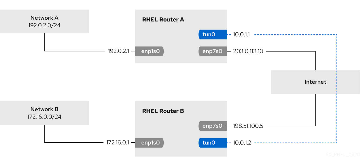
Prerequisites
- Each RHEL router has a network interface that is connected to its local subnet.
- Each RHEL router has a network interface that is connected to the internet.
- The traffic you want to send through the tunnel is IPv4 unicast.
Procedure
On the RHEL router in network A:
Create an IPIP tunnel interface named
tun0:# nmcli connection add type ip-tunnel ip-tunnel.mode ipip con-name tun0 ifname tun0 remote 198.51.100.5 local 203.0.113.10The
remoteandlocalparameters set the public IP addresses of the remote and the local routers.Set the IPv4 address to the
tun0device:# nmcli connection modify tun0 ipv4.addresses '10.0.1.1/30'Note that a
/30subnet with two usable IP addresses is sufficient for the tunnel.Configure the
tun0connection to use a manual IPv4 configuration:# nmcli connection modify tun0 ipv4.method manualAdd a static route that routes traffic to the
172.16.0.0/24network to the tunnel IP on router B:# nmcli connection modify tun0 +ipv4.routes "172.16.0.0/24 10.0.1.2"Enable the
tun0connection.# nmcli connection up tun0Enable packet forwarding:
# echo "net.ipv4.ip_forward=1" > /etc/sysctl.d/95-IPv4-forwarding.conf # sysctl -p /etc/sysctl.d/95-IPv4-forwarding.conf
On the RHEL router in network B:
Create an IPIP tunnel interface named
tun0:# nmcli connection add type ip-tunnel ip-tunnel.mode ipip con-name tun0 ifname tun0 remote 203.0.113.10 local 198.51.100.5The
remoteandlocalparameters set the public IP addresses of the remote and local routers.Set the IPv4 address to the
tun0device:# nmcli connection modify tun0 ipv4.addresses '10.0.1.2/30'Configure the
tun0connection to use a manual IPv4 configuration:# nmcli connection modify tun0 ipv4.method manualAdd a static route that routes traffic to the
192.0.2.0/24network to the tunnel IP on router A:# nmcli connection modify tun0 +ipv4.routes "192.0.2.0/24 10.0.1.1"Enable the
tun0connection.# nmcli connection up tun0Enable packet forwarding:
# echo "net.ipv4.ip_forward=1" > /etc/sysctl.d/95-IPv4-forwarding.conf # sysctl -p /etc/sysctl.d/95-IPv4-forwarding.conf
Verification
From each RHEL router, ping the IP address of the internal interface of the other router:
On Router A, ping
172.16.0.1:# ping 172.16.0.1On Router B, ping
192.0.2.1:# ping 192.0.2.1
9.2. Configuring a GRE tunnel to encapsulate layer-3 traffic in IPv4 packets
A Generic Routing Encapsulation (GRE) tunnel encapsulates layer-3 traffic in IPv4 packets as described in RFC 2784. A GRE tunnel can encapsulate any layer 3 protocol with a valid Ethernet type.
Data sent through a GRE tunnel is not encrypted. For security reasons, use the tunnel only for data that is already encrypted, for example, by other protocols, such as HTTPS.
For example, you can create a GRE tunnel between two RHEL routers to connect two internal subnets over the internet as shown in the following diagram:

Prerequisites
- Each RHEL router has a network interface that is connected to its local subnet.
- Each RHEL router has a network interface that is connected to the internet.
Procedure
On the RHEL router in network A:
Create a GRE tunnel interface named
gre1:# nmcli connection add type ip-tunnel ip-tunnel.mode gre con-name gre1 ifname gre1 remote 198.51.100.5 local 203.0.113.10The
remoteandlocalparameters set the public IP addresses of the remote and the local routers.ImportantThe
gre0device name is reserved. Usegre1or a different name for the device.Set the IPv4 address to the
gre1device:# nmcli connection modify gre1 ipv4.addresses '10.0.1.1/30'Note that a
/30subnet with two usable IP addresses is sufficient for the tunnel.Configure the
gre1connection to use a manual IPv4 configuration:# nmcli connection modify gre1 ipv4.method manualAdd a static route that routes traffic to the
172.16.0.0/24network to the tunnel IP on router B:# nmcli connection modify gre1 +ipv4.routes "172.16.0.0/24 10.0.1.2"Enable the
gre1connection.# nmcli connection up gre1Enable packet forwarding:
# echo "net.ipv4.ip_forward=1" > /etc/sysctl.d/95-IPv4-forwarding.conf # sysctl -p /etc/sysctl.d/95-IPv4-forwarding.conf
On the RHEL router in network B:
Create a GRE tunnel interface named
gre1:# nmcli connection add type ip-tunnel ip-tunnel.mode gre con-name gre1 ifname gre1 remote 203.0.113.10 local 198.51.100.5The
remoteandlocalparameters set the public IP addresses of the remote and the local routers.Set the IPv4 address to the
gre1device:# nmcli connection modify gre1 ipv4.addresses '10.0.1.2/30'Configure the
gre1connection to use a manual IPv4 configuration:# nmcli connection modify gre1 ipv4.method manualAdd a static route that routes traffic to the
192.0.2.0/24network to the tunnel IP on router A:# nmcli connection modify gre1 +ipv4.routes "192.0.2.0/24 10.0.1.1"Enable the
gre1connection.# nmcli connection up gre1Enable packet forwarding:
# echo "net.ipv4.ip_forward=1" > /etc/sysctl.d/95-IPv4-forwarding.conf # sysctl -p /etc/sysctl.d/95-IPv4-forwarding.conf
Verification
From each RHEL router, ping the IP address of the internal interface of the other router:
On Router A, ping
172.16.0.1:# ping 172.16.0.1On Router B, ping
192.0.2.1:# ping 192.0.2.1
9.3. Configuring a GRETAP tunnel to transfer Ethernet frames over IPv4
A Generic Routing Encapsulation Terminal Access Point (GRETAP) tunnel operates on OSI level 2 and encapsulates Ethernet traffic in IPv4 packets as described in RFC 2784.
Data sent through a GRETAP tunnel is not encrypted. For security reasons, establish the tunnel over a VPN or a different encrypted connection.
For example, you can create a GRETAP tunnel between two RHEL routers to connect two networks using a bridge as shown in the following diagram:
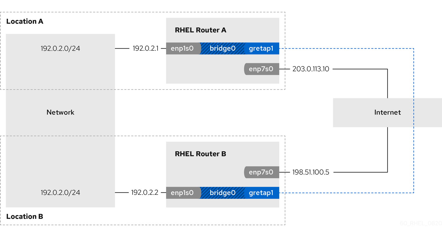
Prerequisites
- Each RHEL router has a network interface that is connected to its local network, and the interface has no IP configuration assigned.
- Each RHEL router has a network interface that is connected to the internet.
Procedure
On the RHEL router in network A:
Create a bridge interface named
bridge0:# nmcli connection add type bridge con-name bridge0 ifname bridge0Configure the IP settings of the bridge:
# nmcli connection modify bridge0 ipv4.addresses '192.0.2.1/24' # nmcli connection modify bridge0 ipv4.method manual
Add a new connection profile for the interface that is connected to local network to the bridge:
# nmcli connection add type ethernet port-type bridge con-name bridge0-port1 ifname enp1s0 controller bridge0Add a new connection profile for the GRETAP tunnel interface to the bridge:
# nmcli connection add type ip-tunnel ip-tunnel.mode gretap port-type bridge con-name bridge0-port2 ifname gretap1 remote 198.51.100.5 local 203.0.113.10 controller bridge0The
remoteandlocalparameters set the public IP addresses of the remote and the local routers.ImportantThe
gretap0device name is reserved. Usegretap1or a different name for the device.Optional: Disable the Spanning Tree Protocol (STP) if you do not need it:
# nmcli connection modify bridge0 bridge.stp noBy default, STP is enabled and causes a delay before you can use the connection.
Configure that activating the
bridge0connection automatically activates the ports of the bridge:# nmcli connection modify bridge0 connection.autoconnect-ports 1Active the
bridge0connection:# nmcli connection up bridge0
On the RHEL router in network B:
Create a bridge interface named
bridge0:# nmcli connection add type bridge con-name bridge0 ifname bridge0Configure the IP settings of the bridge:
# nmcli connection modify bridge0 ipv4.addresses '192.0.2.2/24' # nmcli connection modify bridge0 ipv4.method manual
Add a new connection profile for the interface that is connected to local network to the bridge:
# nmcli connection add type ethernet port-type bridge con-name bridge0-port1 ifname enp1s0 controller bridge0Add a new connection profile for the GRETAP tunnel interface to the bridge:
# nmcli connection add type ip-tunnel ip-tunnel.mode gretap port-type bridge con-name bridge0-port2 ifname gretap1 remote 203.0.113.10 local 198.51.100.5 controller bridge0The
remoteandlocalparameters set the public IP addresses of the remote and the local routers.Optional: Disable the Spanning Tree Protocol (STP) if you do not need it:
# nmcli connection modify bridge0 bridge.stp noConfigure that activating the
bridge0connection automatically activates the ports of the bridge:# nmcli connection modify bridge0 connection.autoconnect-ports 1Active the
bridge0connection:# nmcli connection up bridge0
Verification
On both routers, verify that the
enp1s0andgretap1connections are connected and that theCONNECTIONcolumn displays the connection name of the port:# nmcli device nmcli device DEVICE TYPE STATE CONNECTION ... bridge0 bridge connected bridge0 enp1s0 ethernet connected bridge0-port1 gretap1 iptunnel connected bridge0-port2From each RHEL router, ping the IP address of the internal interface of the other router:
On Router A, ping
192.0.2.2:# ping 192.0.2.2On Router B, ping
192.0.2.1:# ping 192.0.2.1
Chapter 10. Using a VXLAN to create a virtual layer-2 domain for VMs
A virtual extensible LAN (VXLAN) is a networking protocol that tunnels layer-2 traffic over an IP network using the UDP protocol. For example, certain virtual machines (VMs), that are running on different hosts can communicate over a VXLAN tunnel. The hosts can be in different subnets or even in different data centers around the world. From the perspective of the VMs, other VMs in the same VXLAN are within the same layer-2 domain:
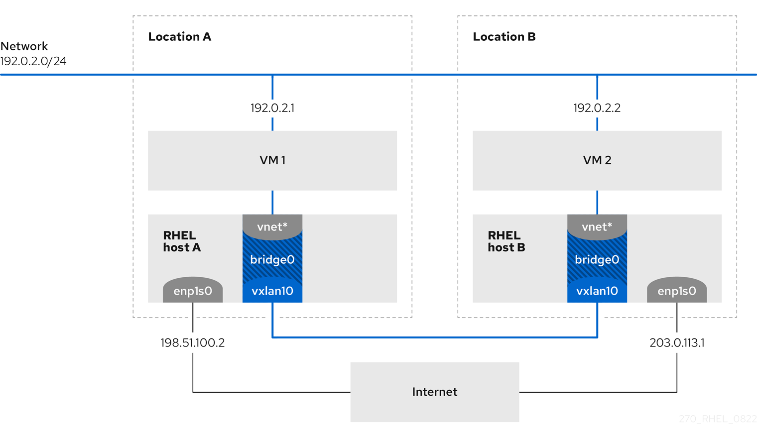
In this example, RHEL-host-A and RHEL-host-B use a bridge, br0, to connect the virtual network of a VM on each host with a VXLAN named vxlan10. Due to this configuration, the VXLAN is invisible to the VMs, and the VMs do not require any special configuration. If you later connect more VMs to the same virtual network, the VMs are automatically members of the same virtual layer-2 domain.
Just as normal layer-2 traffic, data in a VXLAN is not encrypted. For security reasons, use a VXLAN over a VPN or other types of encrypted connections.
10.1. Benefits of VXLANs
A virtual extensible LAN (VXLAN) provides the following major benefits:
- VXLANs use a 24-bit ID. Therefore, you can create up to 16,777,216 isolated networks. For example, a virtual LAN (VLAN), supports only 4,096 isolated networks.
- VXLANs use the IP protocol. This enables you to route the traffic and virtually run systems in different networks and locations within the same layer-2 domain.
- Unlike most tunnel protocols, a VXLAN is not only a point-to-point network. A VXLAN can learn the IP addresses of the other endpoints either dynamically or use statically-configured forwarding entries.
- Certain network cards support UDP tunnel-related offload features.
Additional resources
-
/usr/share/doc/kernel-doc-<kernel_version>/Documentation/networking/vxlan.rstprovided by thekernel-docpackage
10.2. Configuring the Ethernet interface on the hosts
To connect a RHEL VM host to the Ethernet, create a network connection profile, configure the IP settings, and activate the profile.
Run this procedure on both RHEL hosts, and adjust the IP address configuration accordingly.
Prerequisites
- The host is connected to the Ethernet.
Procedure
Add a new Ethernet connection profile to NetworkManager:
# nmcli connection add con-name Example ifname enp1s0 type ethernetConfigure the IPv4 settings:
# nmcli connection modify Example ipv4.addresses 198.51.100.2/24 ipv4.method manual ipv4.gateway 198.51.100.254 ipv4.dns 198.51.100.200 ipv4.dns-search example.comSkip this step if the network uses DHCP.
Activate the
Exampleconnection:# nmcli connection up Example
Verification
Display the status of the devices and connections:
# nmcli device status DEVICE TYPE STATE CONNECTION enp1s0 ethernet connected Example
Ping a host in a remote network to verify the IP settings:
# ping RHEL-host-B.example.comNote that you cannot ping the other VM host before you have configured the network on that host as well.
Additional resources
-
nm-settings(5)man page on your system
10.3. Creating a network bridge with a VXLAN attached
To make a virtual extensible LAN (VXLAN) invisible to virtual machines (VMs), create a bridge on a host, and attach the VXLAN to the bridge. Use NetworkManager to create both the bridge and the VXLAN. You do not add any traffic access point (TAP) devices of the VMs, typically named vnet* on the host, to the bridge. The libvirtd service adds them dynamically when the VMs start.
Run this procedure on both RHEL hosts, and adjust the IP addresses accordingly.
Procedure
Create the bridge
br0:# nmcli connection add type bridge con-name br0 ifname br0 ipv4.method disabled ipv6.method disabledThis command sets no IPv4 and IPv6 addresses on the bridge device, because this bridge works on layer 2.
Create the VXLAN interface and attach it to
br0:# nmcli connection add type vxlan port-type bridge con-name br0-vxlan10 ifname vxlan10 id 10 local 198.51.100.2 remote 203.0.113.1 controller br0This command uses the following settings:
-
id 10: Sets the VXLAN identifier. -
local 198.51.100.2: Sets the source IP address of outgoing packets. -
remote 203.0.113.1: Sets the unicast or multicast IP address to use in outgoing packets when the destination link layer address is not known in the VXLAN device forwarding database. -
controller br0: Sets this VXLAN connection to be created as a port in thebr0connection. -
ipv4.method disabledandipv6.method disabled: Disables IPv4 and IPv6 on the bridge.
By default, NetworkManager uses
8472as the destination port. If the destination port is different, additionally, pass thedestination-port <port_number>option to the command.-
Activate the
br0connection profile:# nmcli connection up br0Open port
8472for incoming UDP connections in the local firewall:# firewall-cmd --permanent --add-port=8472/udp # firewall-cmd --reload
Verification
Display the forwarding table:
# bridge fdb show dev vxlan10 2a:53:bd:d5:b3:0a master br0 permanent 00:00:00:00:00:00 dst 203.0.113.1 self permanent ...
Additional resources
-
nm-settings(5)man page on your system
10.4. Creating a virtual network in libvirt with an existing bridge
To enable virtual machines (VM) to use the br0 bridge with the attached virtual extensible LAN (VXLAN), first add a virtual network to the libvirtd service that uses this bridge.
Prerequisites
-
You installed the
libvirtpackage. -
You started and enabled the
libvirtdservice. -
You configured the
br0device with the VXLAN on RHEL.
Procedure
Create the
~/vxlan10-bridge.xmlfile with the following content:<network> <name>vxlan10-bridge</name> <forward mode="bridge" /> <bridge name="br0" /> </network>
Use the
~/vxlan10-bridge.xmlfile to create a new virtual network inlibvirt:# virsh net-define ~/vxlan10-bridge.xmlRemove the
~/vxlan10-bridge.xmlfile:# rm ~/vxlan10-bridge.xmlStart the
vxlan10-bridgevirtual network:# virsh net-start vxlan10-bridgeConfigure the
vxlan10-bridgevirtual network to start automatically when thelibvirtdservice starts:# virsh net-autostart vxlan10-bridge
Verification
Display the list of virtual networks:
# virsh net-list Name State Autostart Persistent ---------------------------------------------------- vxlan10-bridge active yes yes ...
Additional resources
-
virsh(1)man page on your system
10.5. Configuring virtual machines to use VXLAN
To configure a VM to use a bridge device with an attached virtual extensible LAN (VXLAN) on the host, create a new VM that uses the vxlan10-bridge virtual network or update the settings of existing VMs to use this network.
Perform this procedure on the RHEL hosts.
Prerequisites
-
You configured the
vxlan10-bridgevirtual network inlibvirtd.
Procedure
To create a new VM and configure it to use the
vxlan10-bridgenetwork, pass the--network network:vxlan10-bridgeoption to thevirt-installcommand when you create the VM:# virt-install ... --network network:vxlan10-bridgeTo change the network settings of an existing VM:
Connect the VM’s network interface to the
vxlan10-bridgevirtual network:# virt-xml VM_name --edit --network network=vxlan10-bridgeShut down the VM, and start it again:
# virsh shutdown VM_name # virsh start VM_name
Verification
Display the virtual network interfaces of the VM on the host:
# virsh domiflist VM_name Interface Type Source Model MAC ------------------------------------------------------------------- vnet1 bridge vxlan10-bridge virtio 52:54:00:c5:98:1c
Display the interfaces attached to the
vxlan10-bridgebridge:# ip link show master vxlan10-bridge 18: vxlan10: <BROADCAST,MULTICAST,UP,LOWER_UP> mtu 1500 qdisc noqueue master br0 state UNKNOWN mode DEFAULT group default qlen 1000 link/ether 2a:53:bd:d5:b3:0a brd ff:ff:ff:ff:ff:ff 19: vnet1: <BROADCAST,MULTICAST,UP,LOWER_UP> mtu 1500 qdisc noqueue master br0 state UNKNOWN mode DEFAULT group default qlen 1000 link/ether 52:54:00:c5:98:1c brd ff:ff:ff:ff:ff:ff
Note that the
libvirtdservice dynamically updates the bridge’s configuration. When you start a VM which uses thevxlan10-bridgenetwork, the correspondingvnet*device on the host appears as a port of the bridge.Use address resolution protocol (ARP) requests to verify whether VMs are in the same VXLAN:
- Start two or more VMs in the same VXLAN.
Send an ARP request from one VM to the other one:
# arping -c 1 192.0.2.2 ARPING 192.0.2.2 from 192.0.2.1 enp1s0 Unicast reply from 192.0.2.2 [52:54:00:c5:98:1c] 1.450ms Sent 1 probe(s) (0 broadcast(s)) Received 1 response(s) (0 request(s), 0 broadcast(s))
If the command shows a reply, the VM is in the same layer-2 domain and, in this case in the same VXLAN.
Install the
iputilspackage to use thearpingutility.
Additional resources
-
virt-install(1)andvirt-xml(1)man pages on your system -
virsh(1)andarping(8)man pages on your system
Chapter 11. Managing wifi connections
RHEL provides multiple utilities and applications to configure and connect to wifi networks, for example:
-
Use the
nmcliutility to configure connections by using the command line. -
Use the
nmtuiapplication to configure connections in a text-based user interface. - Use the GNOME system menu to quickly connect to wifi networks that do not require any configuration.
-
Use the
GNOME Settingsapplication to configure connections by using the GNOME application. -
Use the
nm-connection-editorapplication to configure connections in a graphical user interface. -
Use the
networkRHEL system role to automate the configuration of connections on one or multiple hosts.
11.1. Supported wifi security types
Depending on the security type a wifi network supports, you can transmit data more or less securely.
Do not connect to wifi networks that do not use encryption or which support only the insecure WEP or WPA standards.
RHEL 9 supports the following wifi security types:
-
None: Encryption is disabled, and data is transferred in plain text over the network. -
Enhanced Open: With opportunistic wireless encryption (OWE), devices negotiate unique pairwise master keys (PMK) to encrypt connections in wireless networks without authentication. -
LEAP: The Lightweight Extensible Authentication Protocol, which was developed by Cisco, is a proprietary version of the extensible authentication protocol (EAP). -
WPA & WPA2 Personal: In personal mode, the Wi-Fi Protected Access (WPA) and Wi-Fi Protected Access 2 (WPA2) authentication methods use a pre-shared key. -
WPA & WPA2 Enterprise: In enterprise mode, WPA and WPA2 use the EAP framework and authenticate users to a remote authentication dial-in user service (RADIUS) server. -
WPA3 Personal: Wi-Fi Protected Access 3 (WPA3) Personal uses simultaneous authentication of equals (SAE) instead of pre-shared keys (PSK) to prevent dictionary attacks. WPA3 uses perfect forward secrecy (PFS).
11.2. Connecting to a wifi network by using nmcli
You can use the nmcli utility to connect to a wifi network. When you attempt to connect to a network for the first time, the utility automatically creates a NetworkManager connection profile for it. If the network requires additional settings, such as static IP addresses, you can then modify the profile after it has been automatically created.
Prerequisites
- A wifi device is installed on the host.
-
The wifi device is enabled. To verify, use the
nmcli radiocommand.
Procedure
If the wifi radio has been disabled in NetworkManager, enable this feature:
# nmcli radio wifi onOptional: Display the available wifi networks:
# nmcli device wifi list IN-USE BSSID SSID MODE CHAN RATE SIGNAL BARS SECURITY 00:53:00:2F:3B:08 Office Infra 44 270 Mbit/s 57 ▂▄▆_ WPA2 WPA3 00:53:00:15:03:BF -- Infra 1 130 Mbit/s 48 ▂▄__ WPA2 WPA3The service set identifier (
SSID) column contains the names of the networks. If the column shows--, the access point of this network does not broadcast an SSID.Connect to the wifi network:
# nmcli device wifi connect Office --ask Password: wifi-password
If you prefer to set the password in the command instead of entering it interactively, use the
password <wifi_password>option in the command instead of--ask:# nmcli device wifi connect Office password <wifi_password>Note that, if the network requires static IP addresses, NetworkManager fails to activate the connection at this point. You can configure the IP addresses in later steps.
If the network requires static IP addresses:
Configure the IPv4 address settings, for example:
# nmcli connection modify Office ipv4.method manual ipv4.addresses 192.0.2.1/24 ipv4.gateway 192.0.2.254 ipv4.dns 192.0.2.200 ipv4.dns-search example.comConfigure the IPv6 address settings, for example:
# nmcli connection modify Office ipv6.method manual ipv6.addresses 2001:db8:1::1/64 ipv6.gateway 2001:db8:1::fffe ipv6.dns 2001:db8:1::ffbb ipv6.dns-search example.com
Re-activate the connection:
# nmcli connection up Office
Verification
Display the active connections:
# nmcli connection show --active NAME ID TYPE DEVICE Office 2501eb7e-7b16-4dc6-97ef-7cc460139a58 wifi wlp0s20f3If the output lists the wifi connection you have created, the connection is active.
Ping a hostname or IP address:
# *ping -c 3 example.com
Additional resources
-
nm-settings-nmcli(5)man page on your system
11.3. Connecting to a wifi network by using the GNOME system menu
You can use the GNOME system menu to connect to a wifi network. When you connect to a network for the first time, GNOME creates a NetworkManager connection profile for it. If you configure the connection profile to not automatically connect, you can also use the GNOME system menu to manually connect to a wifi network with an existing NetworkManager connection profile.
Using the GNOME system menu to establish a connection to a wifi network for the first time has certain limitations. For example, you can not configure IP address settings. In this case first configure the connections:
Prerequisites
- A wifi device is installed on the host.
-
The wifi device is enabled. To verify, use the
nmcli radiocommand.
Procedure
- Open the system menu on the right side of the top bar.
-
Expand the
Wi-Fi Not Connectedentry. Click
Select Network: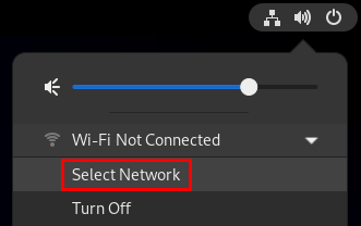
- Select the wifi network you want to connect to.
-
Click
Connect. -
If this is the first time you connect to this network, enter the password for the network, and click
Connect.
Verification
Open the system menu on the right side of the top bar, and verify that the wifi network is connected:
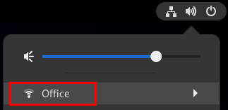
If the network appears in the list, it is connected.
Ping a hostname or IP address:
# ping -c 3 example.com
11.4. Connecting to a wifi network by using the GNOME settings application
You can use the GNOME settings application, also named gnome-control-center, to connect to a wifi network and configure the connection. When you connect to the network for the first time, GNOME creates a NetworkManager connection profile for it.
In GNOME settings, you can configure wifi connections for all wifi network security types that RHEL supports.
Prerequisites
- A wifi device is installed on the host.
-
The wifi device is enabled. To verify, use the
nmcli radiocommand.
Procedure
-
Press the Super key, type
Wi-Fi, and press Enter. - Click on the name of the wifi network you want to connect to.
-
Enter the password for the network, and click
Connect. If the network requires additional settings, such as static IP addresses or a security type other than WPA2 Personal:
- Click the gear icon next to the network’s name.
Optional: Configure the network profile on the
Detailstab to not automatically connect.If you deactivate this feature, you must always manually connect to the network, for example, by using
GNOME settingsor the GNOME system menu.-
Configure IPv4 settings on the
IPv4tab, and IPv6 settings on theIPv6tab. On the
Securitytab, select the authentication of the network, such asWPA3 Personal, and enter the password.Depending on the selected security, the application shows additional fields. Fill them accordingly. For details, ask the administrator of the wifi network.
-
Click
Apply.
Verification
Open the system menu on the right side of the top bar, and verify that the wifi network is connected:
If the network appears in the list, it is connected.
Ping a hostname or IP address:
# ping -c 3 example.com
11.5. Configuring a wifi connection by using nmtui
The nmtui application provides a text-based user interface for NetworkManager. You can use nmtui to connect to a wifi network.
In nmtui:
- Navigate by using the cursor keys.
- Press a button by selecting it and hitting Enter.
- Select and clear checkboxes by using Space.
- To return to the previous screen, use ESC.
Procedure
Start
nmtui:# nmtui-
Select
Edit a connection, and press Enter. -
Press the
Addbutton. -
Select
Wi-Fifrom the list of network types, and press Enter. Optional: Enter a name for the NetworkManager profile to be created.
On hosts with multiple profiles, a meaningful name makes it easier to identify the purpose of a profile.
-
Enter the name of the Wi-Fi network, the Service Set Identifier (SSID), into the
SSIDfield. -
Leave the
Modefield set to its default,Client. Select the
Securityfield, press Enter, and set the authentication type of the network from the list.Depending on the authentication type you have selected,
nmtuidisplays different fields.- Fill the authentication type-related fields.
If the Wi-Fi network requires static IP addresses:
-
Press the
Automaticbutton next to the protocol, and selectManualfrom the displayed list. -
Press the
Showbutton next to the protocol you want to configure to display additional fields, and fill them.
-
Press the
Press the
OKbutton to create and automatically activate the new connection.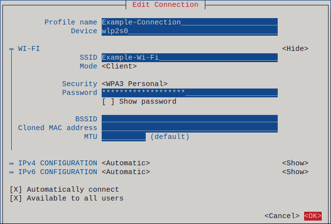
-
Press the
Backbutton to return to the main menu. -
Select
Quit, and press Enter to close thenmtuiapplication.
Verification
Display the active connections:
# nmcli connection show --active NAME ID TYPE DEVICE Office 2501eb7e-7b16-4dc6-97ef-7cc460139a58 wifi wlp0s20f3If the output lists the wifi connection you have created, the connection is active.
Ping a hostname or IP address:
# ping -c 3 example.com
11.6. Configuring a wifi connection by using nm-connection-editor
You can use the nm-connection-editor application to create a connection profile for a wireless network. In this application you can configure all wifi network authentication types that RHEL supports.
By default, NetworkManager enables the auto-connect feature for connection profiles and automatically connects to a saved network if it is available.
Prerequisites
- A wifi device is installed on the host.
-
The wifi device is enabled. To verify, use the
nmcli radiocommand.
Procedure
Open a terminal and enter:
# nm-connection-editor- Click the button to add a new connection.
-
Select the
Wi-Ficonnection type, and click . - Optional: Set a name for the connection profile.
Optional: Configure the network profile on the
Generaltab to not automatically connect.If you deactivate this feature, you must always manually connect to the network, for example, by using
GNOME settingsor the GNOME system menu.-
On the
Wi-Fitab, enter the service set identifier (SSID) in theSSIDfield. On the
Wi-Fi Securitytab, select the authentication type for the network, such asWPA3 Personal, and enter the password.Depending on the selected security, the application shows additional fields. Fill them accordingly. For details, ask the administrator of the wifi network.
-
Configure IPv4 settings on the
IPv4tab, and IPv6 settings on theIPv6tab. -
Click
Save. -
Close the
Network Connectionswindow.
Verification
Open the system menu on the right side of the top bar, and verify that the wifi network is connected:
If the network appears in the list, it is connected.
Ping a hostname or IP address:
# ping -c 3 example.com
11.7. Configuring a wifi connection with 802.1X network authentication by using the network RHEL system role
Network Access Control (NAC) protects a network from unauthorized clients. You can specify the details that are required for the authentication in NetworkManager connection profiles to enable clients to access the network. By using Ansible and the network RHEL system role, you can automate this process and remotely configure connection profiles on the hosts defined in a playbook.
You can use an Ansible playbook to copy a private key, a certificate, and the CA certificate to the client, and then use the network RHEL system role to configure a connection profile with 802.1X network authentication.
Prerequisites
- You have prepared the control node and the managed nodes
- You are logged in to the control node as a user who can run playbooks on the managed nodes.
-
The account you use to connect to the managed nodes has
sudopermissions on them. - The network supports 802.1X network authentication.
-
You installed the
wpa_supplicantpackage on the managed node. - DHCP is available in the network of the managed node.
The following files required for TLS authentication exist on the control node:
-
The client key is stored in the
/srv/data/client.keyfile. -
The client certificate is stored in the
/srv/data/client.crtfile. -
The CA certificate is stored in the
/srv/data/ca.crtfile.
-
The client key is stored in the
Procedure
Store your sensitive variables in an encrypted file:
Create the vault:
$ ansible-vault create vault.yml New Vault password: <vault_password> Confirm New Vault password: <vault_password>
After the
ansible-vault createcommand opens an editor, enter the sensitive data in the<key>: <value>format:pwd: <password>- Save the changes, and close the editor. Ansible encrypts the data in the vault.
Create a playbook file, for example
~/playbook.yml, with the following content:--- - name: Configure a wifi connection with 802.1X authentication hosts: managed-node-01.example.com tasks: - name: Copy client key for 802.1X authentication ansible.builtin.copy: src: "/srv/data/client.key" dest: "/etc/pki/tls/private/client.key" mode: 0400 - name: Copy client certificate for 802.1X authentication ansible.builtin.copy: src: "/srv/data/client.crt" dest: "/etc/pki/tls/certs/client.crt" - name: Copy CA certificate for 802.1X authentication ansible.builtin.copy: src: "/srv/data/ca.crt" dest: "/etc/pki/ca-trust/source/anchors/ca.crt" - name: Wifi connection profile with dynamic IP address settings and 802.1X ansible.builtin.import_role: name: rhel-system-roles.network vars: network_connections: - name: Wifi connection profile with dynamic IP address settings and 802.1X interface_name: wlp1s0 state: up type: wireless autoconnect: yes ip: dhcp4: true auto6: true wireless: ssid: "Example-wifi" key_mgmt: "wpa-eap" ieee802_1x: identity: <user_name> eap: tls private_key: "/etc/pki/tls/client.key" private_key_password: "{{ pwd }}" private_key_password_flags: none client_cert: "/etc/pki/tls/client.pem" ca_cert: "/etc/pki/tls/cacert.pem" domain_suffix_match: "example.com"The settings specified in the example playbook include the following:
ieee802_1x- This variable contains the 802.1X-related settings.
eap: tls-
Configures the profile to use the certificate-based
TLSauthentication method for the Extensible Authentication Protocol (EAP).
For details about all variables used in the playbook, see the
/usr/share/ansible/roles/rhel-system-roles.network/README.mdfile on the control node.Validate the playbook syntax:
$ ansible-playbook --ask-vault-pass --syntax-check ~/playbook.ymlNote that this command only validates the syntax and does not protect against a wrong but valid configuration.
Run the playbook:
$ ansible-playbook --ask-vault-pass ~/playbook.yml
Additional resources
-
/usr/share/ansible/roles/rhel-system-roles.network/README.mdfile -
/usr/share/doc/rhel-system-roles/network/directory
11.8. Configuring a wifi connection with 802.1X network authentication in an existing profile by using nmcli
Using the nmcli utility, you can configure the client to authenticate itself to the network. For example, you can configure Protected Extensible Authentication Protocol (PEAP) authentication with the Microsoft Challenge-Handshake Authentication Protocol version 2 (MSCHAPv2) in an existing NetworkManager wifi connection profile named wlp1s0.
Prerequisites
- The network must have 802.1X network authentication.
- The wifi connection profile exists in NetworkManager and has a valid IP configuration.
-
If the client is required to verify the certificate of the authenticator, the Certificate Authority (CA) certificate must be stored in the
/etc/pki/ca-trust/source/anchors/directory. -
The
wpa_supplicantpackage is installed.
Procedure
Set the wifi security mode to
wpa-eap, the Extensible Authentication Protocol (EAP) topeap, the inner authentication protocol tomschapv2, and the user name:# nmcli connection modify wlp1s0 wireless-security.key-mgmt wpa-eap 802-1x.eap peap 802-1x.phase2-auth mschapv2 802-1x.identity user_nameNote that you must set the
wireless-security.key-mgmt,802-1x.eap,802-1x.phase2-auth, and802-1x.identityparameters in a single command.Optional: Store the password in the configuration:
# nmcli connection modify wlp1s0 802-1x.password passwordImportantBy default, NetworkManager stores the password in plain text in the
/etc/sysconfig/network-scripts/keys-connection_namefile, which is readable only by therootuser. However, plain text passwords in a configuration file can be a security risk.To increase the security, set the
802-1x.password-flagsparameter toagent-owned. With this setting, on servers with the GNOME desktop environment or thenm-appletrunning, NetworkManager retrieves the password from these services, after you unlock the keyring first. In other cases, NetworkManager prompts for the password.If the client needs to verify the certificate of the authenticator, set the
802-1x.ca-certparameter in the connection profile to the path of the CA certificate:# nmcli connection modify wlp1s0 802-1x.ca-cert /etc/pki/ca-trust/source/anchors/ca.crtNoteFor security reasons, clients should validate the certiciate of the authenticator.
Activate the connection profile:
# nmcli connection up wlp1s0
Verification
- Access resources on the network that require network authentication.
Additional resources
- Managing wifi connections
-
nm-settings(5)andnmcli(1)man pages on your system
11.9. Manually setting the wireless regulatory domain
On RHEL, a udev rule executes the setregdomain utility to set the wireless regulatory domain. The utility then provides this information to the kernel.
By default, setregdomain attempts to determine the country code automatically. If this fails, the wireless regulatory domain setting might be wrong. To work around this problem, you can manually set the country code.
Manually setting the regulatory domain disables the automatic detection. Therefore, if you later use the computer in a different country, the previously configured setting might no longer be correct. In this case, remove the /etc/sysconfig/regdomain file to switch back to automatic detection or use this procedure to manually update the regulatory domain setting again.
Prerequisites
- The driver of the wifi device supports changing the regulatory domain.
Procedure
Optional: Display the current regulatory domain settings:
# iw reg get global country US: DFS-FCC ...Create the
/etc/sysconfig/regdomainfile with the following content:COUNTRY=<country_code>Set the
COUNTRYvariable to an ISO 3166-1 alpha2 country code, such asDEfor Germany orUSfor the United States of America.Set the regulatory domain:
# setregdomain
Verification
Display the regulatory domain settings:
# iw reg get global country DE: DFS-ETSI ...
Additional resources
-
iw(8),setregdomain(1), andregulatory.bin(5)man pages on your system - ISO 3166 Country Codes
Chapter 12. Configuring RHEL as a WPA2 or WPA3 Personal access point
On a host with a wifi device, you can use NetworkManager to configure this host as an access point. Wi-Fi Protected Access 2 (WPA2) and Wi-Fi Protected Access 3 (WPA3) Personal provide secure authentication methods, and wireless clients can use a pre-shared key (PSK) to connect to the access point and use services on the RHEL host and in the network.
When you configure an access point, NetworkManager automatically:
-
Configures the
dnsmasqservice to provide DHCP and DNS services for clients - Enables IP forwarding
-
Adds
nftablesfirewall rules to masquerade traffic from the wifi device and configures IP forwarding
Prerequisites
- The wifi device supports running in access point mode.
- The wifi device is not in use.
- The host has internet access.
Procedure
List the wifi devices to identify the one that should provide the access point:
# nmcli device status | grep wifi wlp0s20f3 wifi disconnected --
Verify that the device supports the access point mode:
# nmcli -f WIFI-PROPERTIES.AP device show wlp0s20f3 WIFI-PROPERTIES.AP: yesTo use a wifi device as an access point, the device must support this feature.
Install the
dnsmasqandNetworkManager-wifipackages:# dnf install dnsmasq NetworkManager-wifiNetworkManager uses the
dnsmasqservice to provide DHCP and DNS services to clients of the access point.Create the initial access point configuration:
# nmcli device wifi hotspot ifname wlp0s20f3 con-name Example-Hotspot ssid Example-Hotspot password "password"This command creates a connection profile for an access point on the
wlp0s20f3device that provides WPA2 and WPA3 Personal authentication. The name of the wireless network, the Service Set Identifier (SSID), isExample-Hotspotand uses the pre-shared keypassword.Optional: Configure the access point to support only WPA3:
# nmcli connection modify Example-Hotspot 802-11-wireless-security.key-mgmt saeBy default, NetworkManager uses the IP address
10.42.0.1for the wifi device and assigns IP addresses from the remaining10.42.0.0/24subnet to clients. To configure a different subnet and IP address, enter:# nmcli connection modify Example-Hotspot ipv4.addresses 192.0.2.254/24The IP address you set, in this case
192.0.2.254, is the one that NetworkManager assigns to the wifi device. Clients will use this IP address as default gateway and DNS server.Activate the connection profile:
# nmcli connection up Example-Hotspot
Verification
On the server:
Verify that NetworkManager started the
dnsmasqservice and that the service listens on port 67 (DHCP) and 53 (DNS):# ss -tulpn | grep -E ":53|:67" udp UNCONN 0 0 10.42.0.1:53 0.0.0.0:* users:(("dnsmasq",pid=55905,fd=6)) udp UNCONN 0 0 0.0.0.0:67 0.0.0.0:* users:(("dnsmasq",pid=55905,fd=4)) tcp LISTEN 0 32 10.42.0.1:53 0.0.0.0:* users:(("dnsmasq",pid=55905,fd=7))
Display the
nftablesrule set to ensure that NetworkManager enabled forwarding and masquerading for traffic from the10.42.0.0/24subnet:# nft list ruleset table ip nm-shared-wlp0s20f3 { chain nat_postrouting { type nat hook postrouting priority srcnat; policy accept; ip saddr 10.42.0.0/24 ip daddr != 10.42.0.0/24 masquerade } chain filter_forward { type filter hook forward priority filter; policy accept; ip daddr 10.42.0.0/24 oifname "wlp0s20f3" ct state { established, related } accept ip saddr 10.42.0.0/24 iifname "wlp0s20f3" accept iifname "wlp0s20f3" oifname "wlp0s20f3" accept iifname "wlp0s20f3" reject oifname "wlp0s20f3" reject } }
On a client with a wifi adapter:
Display the list of available networks:
# nmcli device wifi IN-USE BSSID SSID MODE CHAN RATE SIGNAL BARS SECURITY 00:53:00:88:29:04 Example-Hotspot Infra 11 130 Mbit/s 62 ▂▄▆_ WPA3 ...
-
Connect to the
Example-Hotspotwireless network. See Managing Wi-Fi connections. Ping a host on the remote network or the internet to verify that the connection works:
# ping -c 3 www.redhat.com
Additional resources
-
nm-settings(5)man page on your system
Chapter 13. Using MACsec to encrypt layer-2 traffic in the same physical network
You can use MACsec to secure the communication between two devices (point-to-point). For example, your branch office is connected over a Metro-Ethernet connection with the central office, you can configure MACsec on the two hosts that connect the offices to increase the security.
13.1. How MACsec increases security
Media Access Control security (MACsec) is a layer-2 protocol that secures different traffic types over the Ethernet links, including:
- Dynamic host configuration protocol (DHCP)
- address resolution protocol (ARP)
- IPv4 and IPv6 traffic
- Any traffic over IP such as TCP or UDP
MACsec encrypts and authenticates all traffic in LANs, by default with the GCM-AES-128 algorithm, and uses a pre-shared key to establish the connection between the participant hosts. To change the pre-shared key, you must update the NM configuration on all network hosts that use MACsec.
A MACsec connection uses an Ethernet device, such as an Ethernet network card, VLAN, or tunnel device, as a parent. You can either set an IP configuration only on the MACsec device to communicate with other hosts only by using the encrypted connection, or you can also set an IP configuration on the parent device. In the latter case, you can use the parent device to communicate with other hosts using an unencrypted connection and the MACsec device for encrypted connections.
MACsec does not require any special hardware. For example, you can use any switch, except if you want to encrypt traffic only between a host and a switch. In this scenario, the switch must also support MACsec.
In other words, you can configure MACsec for two common scenarios:
- Host-to-host
- Host-to-switch and switch-to-other-hosts
You can use MACsec only between hosts being in the same physical or virtual LAN.
Additional resources
13.2. Configuring a MACsec connection by using nmcli
You can use the nmcli utility to configure Ethernet interfaces to use MACsec. For example, you can create a MACsec connection between two hosts that are connected over Ethernet.
Procedure
On the first host on which you configure MACsec:
Create the connectivity association key (CAK) and connectivity-association key name (CKN) for the pre-shared key:
Create a 16-byte hexadecimal CAK:
# dd if=/dev/urandom count=16 bs=1 2> /dev/null | hexdump -e '1/2 "%04x"' 50b71a8ef0bd5751ea76de6d6c98c03aCreate a 32-byte hexadecimal CKN:
# dd if=/dev/urandom count=32 bs=1 2> /dev/null | hexdump -e '1/2 "%04x"' f2b4297d39da7330910a74abc0449feb45b5c0b9fc23df1430e1898fcf1c4550
- On both hosts you want to connect over a MACsec connection:
Create the MACsec connection:
# nmcli connection add type macsec con-name macsec0 ifname macsec0 connection.autoconnect yes macsec.parent enp1s0 macsec.mode psk macsec.mka-cak 50b71a8ef0bd5751ea76de6d6c98c03a macsec.mka-ckn f2b4297d39da7330910a74abc0449feb45b5c0b9fc23df1430e1898fcf1c4550Use the CAK and CKN generated in the previous step in the
macsec.mka-cakandmacsec.mka-cknparameters. The values must be the same on every host in the MACsec-protected network.Configure the IP settings on the MACsec connection.
Configure the
IPv4settings. For example, to set a staticIPv4address, network mask, default gateway, and DNS server to themacsec0connection, enter:# nmcli connection modify macsec0 ipv4.method manual ipv4.addresses '192.0.2.1/24' ipv4.gateway '192.0.2.254' ipv4.dns '192.0.2.253'Configure the
IPv6settings. For example, to set a staticIPv6address, network mask, default gateway, and DNS server to themacsec0connection, enter:# nmcli connection modify macsec0 ipv6.method manual ipv6.addresses '2001:db8:1::1/32' ipv6.gateway '2001:db8:1::fffe' ipv6.dns '2001:db8:1::fffd'
Activate the connection:
# nmcli connection up macsec0
Verification
Verify that the traffic is encrypted:
# tcpdump -nn -i enp1s0Optional: Display the unencrypted traffic:
# tcpdump -nn -i macsec0Display MACsec statistics:
# ip macsec showDisplay individual counters for each type of protection: integrity-only (encrypt off) and encryption (encrypt on)
# ip -s macsec show
Additional resources
13.3. Configuring a MACsec connection by using nmstatectl
You can configure Ethernet interfaces to use MACsec through the nmstatectl utility in a declarative way. For example, in a YAML file, you describe the desired state of your network, which is supposed to have a MACsec connection between two hosts connected over Ethernet. The nmstatectl utility interprets the YAML file and deploys persistent and consistent network configuration across the hosts.
Using the MACsec security standard for securing communication at the link layer, also known as layer 2 of the Open Systems Interconnection (OSI) model provides the following notable benefits:
- Encryption at layer 2 eliminates the need for encrypting individual services at layer 7. This reduces the overhead associated with managing a large number of certificates for each endpoint on each host.
- Point-to-point security between directly connected network devices such as routers and switches.
- No changes needed for applications and higher-layer protocols.
Prerequisites
- A physical or virtual Ethernet Network Interface Controller (NIC) exists in the server configuration.
-
The
nmstatepackage is installed.
Procedure
On the first host on which you configure MACsec, create the connectivity association key (CAK) and connectivity-association key name (CKN) for the pre-shared key:
Create a 16-byte hexadecimal CAK:
# dd if=/dev/urandom count=16 bs=1 2> /dev/null | hexdump -e '1/2 "%04x"' 50b71a8ef0bd5751ea76de6d6c98c03aCreate a 32-byte hexadecimal CKN:
# dd if=/dev/urandom count=32 bs=1 2> /dev/null | hexdump -e '1/2 "%04x"' f2b4297d39da7330910a74abc0449feb45b5c0b9fc23df1430e1898fcf1c4550
On both hosts that you want to connect over a MACsec connection, complete the following steps:
Create a YAML file, for example
create-macsec-connection.yml, with the following settings:--- routes: config: - destination: 0.0.0.0/0 next-hop-interface: macsec0 next-hop-address: 192.0.2.2 table-id: 254 - destination: 192.0.2.2/32 next-hop-interface: macsec0 next-hop-address: 0.0.0.0 table-id: 254 dns-resolver: config: search: - example.com server: - 192.0.2.200 - 2001:db8:1::ffbb interfaces: - name: macsec0 type: macsec state: up ipv4: enabled: true address: - ip: 192.0.2.1 prefix-length: 32 ipv6: enabled: true address: - ip: 2001:db8:1::1 prefix-length: 64 macsec: encrypt: true base-iface: enp0s1 mka-cak: 50b71a8ef0bd5751ea76de6d6c98c03a mka-ckn: f2b4297d39da7330910a74abc0449feb45b5c0b9fc23df1430e1898fcf1c4550 port: 0 validation: strict send-sci: true-
Use the CAK and CKN generated in the previous step in the
mka-cakandmka-cknparameters. The values must be the same on every host in the MACsec-protected network. Optional: In the same YAML configuration file, you can also configure the following settings:
-
A static IPv4 address -
192.0.2.1with the/32subnet mask -
A static IPv6 address -
2001:db8:1::1with the/64subnet mask -
An IPv4 default gateway -
192.0.2.2 -
An IPv4 DNS server -
192.0.2.200 -
An IPv6 DNS server -
2001:db8:1::ffbb -
A DNS search domain -
example.com
-
A static IPv4 address -
Apply the settings to the system:
# nmstatectl apply create-macsec-connection.yml
Verification
Display the current state in YAML format:
# nmstatectl show macsec0Verify that the traffic is encrypted:
# tcpdump -nn -i enp0s1Optional: Display the unencrypted traffic:
# tcpdump -nn -i macsec0Display MACsec statistics:
# ip macsec showDisplay individual counters for each type of protection: integrity-only (encrypt off) and encryption (encrypt on)
# ip -s macsec show
Additional resources
Chapter 14. Getting started with IPVLAN
IPVLAN is a driver for a virtual network device that can be used in container environment to access the host network. IPVLAN exposes a single MAC address to the external network regardless the number of IPVLAN device created inside the host network. This means that a user can have multiple IPVLAN devices in multiple containers and the corresponding switch reads a single MAC address. IPVLAN driver is useful when the local switch imposes constraints on the total number of MAC addresses that it can manage.
14.1. IPVLAN modes
The following modes are available for IPVLAN:
L2 mode
In IPVLAN L2 mode, virtual devices receive and respond to address resolution protocol (ARP) requests. The
netfilterframework runs only inside the container that owns the virtual device. Nonetfilterchains are executed in the default namespace on the containerized traffic. Using L2 mode provides good performance, but less control on the network traffic.L3 mode
In L3 mode, virtual devices process only L3 traffic and above. Virtual devices do not respond to ARP request and users must configure the neighbour entries for the IPVLAN IP addresses on the relevant peers manually. The egress traffic of a relevant container is landed on the
netfilterPOSTROUTING and OUTPUT chains in the default namespace while the ingress traffic is threaded in the same way as L2 mode. Using L3 mode provides good control but decreases the network traffic performance.L3S mode
In L3S mode, virtual devices process the same way as in L3 mode, except that both egress and ingress traffics of a relevant container are landed on
netfilterchain in the default namespace. L3S mode behaves in a similar way to L3 mode but provides greater control of the network.
The IPVLAN virtual device does not receive broadcast and multicast traffic in case of L3 and L3S modes.
14.2. Comparison of IPVLAN and MACVLAN
The following table shows the major differences between MACVLAN and IPVLAN:
| MACVLAN | IPVLAN |
|---|---|
| Uses MAC address for each MACVLAN device. Note that, if a switch reaches the maximum number of MAC addresses it can store in its MAC table, connectivity can be lost. | Uses single MAC address which does not limit the number of IPVLAN devices. |
| Netfilter rules for a global namespace cannot affect traffic to or from a MACVLAN device in a child namespace. | It is possible to control traffic to or from a IPVLAN device in L3 mode and L3S mode. |
Both IPVLAN and MACVLAN do not require any level of encapsulation.
14.3. Creating and configuring the IPVLAN device using iproute2
This procedure shows how to set up the IPVLAN device using iproute2.
Procedure
To create an IPVLAN device, enter the following command:
# ip link add link real_NIC_device name IPVLAN_device type ipvlan mode l2Note that network interface controller (NIC) is a hardware component which connects a computer to a network.
Example 14.1. Creating an IPVLAN device
# ip link add link enp0s31f6 name my_ipvlan type ipvlan mode l2 # ip link 47: my_ipvlan@enp0s31f6: <BROADCAST,MULTICAST> mtu 1500 qdisc noop state DOWN mode DEFAULT group default qlen 1000 link/ether e8:6a:6e:8a:a2:44 brd ff:ff:ff:ff:ff:ff
To assign an
IPv4orIPv6address to the interface, enter the following command:# ip addr add dev IPVLAN_device IP_address/subnet_mask_prefixIn case of configuring an IPVLAN device in L3 mode or L3S mode, make the following setups:
Configure the neighbor setup for the remote peer on the remote host:
# ip neigh add dev peer_device IPVLAN_device_IP_address lladdr MAC_addresswhere MAC_address is the MAC address of the real NIC on which an IPVLAN device is based on.
Configure an IPVLAN device for L3 mode with the following command:
# ip route add dev <real_NIC_device> <peer_IP_address/32>For L3S mode:
# ip route add dev real_NIC_device peer_IP_address/32where IP-address represents the address of the remote peer.
To set an IPVLAN device active, enter the following command:
# ip link set dev IPVLAN_device upTo check if the IPVLAN device is active, execute the following command on the remote host:
# ping IP_addresswhere the IP_address uses the IP address of the IPVLAN device.
Chapter 15. Configuring NetworkManager to ignore certain devices
By default, NetworkManager manages all devices except the ones described in the /usr/lib/udev/rules.d/85-nm-unmanaged.rules file. To ignore certain other devices, you can configure them in NetworkManager as unmanaged.
15.1. Permanently configuring a device as unmanaged in NetworkManager
You can permanently configure devices as unmanaged based on several criteria, such as the interface name, MAC address, or device type.
Procedure
Optional: Display the list of devices to identify the device or MAC address you want to set as
unmanaged:# ip link show ... 2: enp1s0: <BROADCAST,MULTICAST,UP,LOWER_UP> mtu 1500 qdisc fq_codel state UP mode DEFAULT group default qlen 1000 link/ether 52:54:00:74:79:56 brd ff:ff:ff:ff:ff:ff ...Create the
/etc/NetworkManager/conf.d/99-unmanaged-devices.conffile with the following content:To configure a specific interface as unmanaged, add:
[keyfile] unmanaged-devices=interface-name:enp1s0
To configure a device with a specific MAC address as unmanaged, add:
[keyfile] unmanaged-devices=mac:52:54:00:74:79:56
To configure all devices of a specific type as unmanaged, add:
[keyfile] unmanaged-devices=type:ethernet
To set multiple devices as unmanaged, separate the entries in the
unmanaged-devicesparameter with a semicolon, for example:[keyfile] unmanaged-devices=interface-name:enp1s0;interface-name:enp7s0
Reload the
NetworkManagerservice:# systemctl reload NetworkManager
Verification
Display the list of devices:
# nmcli device status DEVICE TYPE STATE CONNECTION enp1s0 ethernet unmanaged -- ...
The
unmanagedstate next to theenp1s0device indicates that NetworkManager does not manage this device.
Troubleshooting
If the device is not shown as
unmanaged, display the NetworkManager configuration:# NetworkManager --print-config ... [keyfile] unmanaged-devices=interface-name:enp1s0 ...If the output does not match the settings that you configured, ensure that no configuration file with a higher priority overrides your settings. For details about how NetworkManager merges multiple configuration files, see the
NetworkManager.conf(5)man page on your system.
15.2. Temporarily configuring a device as unmanaged in NetworkManager
You can temporarily configure devices as unmanaged, for example, for testing purposes.
Procedure
Optional: Display the list of devices to identify the device you want to set as
unmanaged:# nmcli device status DEVICE TYPE STATE CONNECTION enp1s0 ethernet disconnected -- ...Set the
enp1s0device to theunmanagedstate:# nmcli device set enp1s0 managed no
Verification
Display the list of devices:
# nmcli device status DEVICE TYPE STATE CONNECTION enp1s0 ethernet unmanaged -- ...
The
unmanagedstate next to theenp1s0device indicates that NetworkManager does not manage this device.
Additional resources
-
NetworkManager.conf(5)man page on your system
Chapter 16. Configuring the loopback interface by using nmcli
By default, NetworkManager does not manage the loopback (lo) interface. After creating a connection profile for the lo interface, you can configure this device by using NetworkManager. Some of the examples are as follows:
-
Assign additional IP addresses to the
lointerface - Define DNS addresses
-
Change the Maximum Transmission Unit (MTU) size of the
lointerface
Procedure
Create a new connection of type
loopback:# nmcli connection add con-name example-loopback type loopbackConfigure custom connection settings, for example:
To assign an additional IP address to the interface, enter:
# nmcli connection modify example-loopback +ipv4.addresses 192.0.2.1/24NoteNetworkManager manages the
lointerface by always assigning the IP addresses127.0.0.1and::1that are persistent across the reboots. You can not override127.0.0.1and::1. However, you can assign additional IP addresses to the interface.To set a custom Maximum Transmission Unit (MTU), enter:
# nmcli con mod example-loopback loopback.mtu 16384To set an IP address to your DNS server, enter:
# nmcli connection modify example-loopback ipv4.dns 192.0.2.0If you set a DNS server in the loopback connection profile, this entry is always available in the
/etc/resolv.conffile. The DNS server entry remains independent of whether or not the host roams between different networks.
Activate the connection:
# nmcli connection up example-loopback
Verification
Display the settings of the
lointerface:# ip address show lo 1: lo: <LOOPBACK,UP,LOWER_UP> mtu 16384 qdisc noqueue state UNKNOWN group default qlen 1000 link/loopback 00:00:00:00:00:00 brd 00:00:00:00:00:00 inet 127.0.0.1/8 scope host lo valid_lft forever preferred_lft forever inet
192.0.2.1/24brd192.0.2.255scope global lo valid_lft forever preferred_lft forever inet6 ::1/128 scope host valid_lft forever preferred_lft foreverVerify the DNS address:
# cat /etc/resolv.conf ... nameserver
192.0.2.0...
Chapter 17. Creating a dummy interface
As a Red Hat Enterprise Linux user, you can create and use dummy network interfaces for debugging and testing purposes. A dummy interface provides a device to route packets without actually transmitting them. It enables you to create additional loopback-like devices managed by NetworkManager and makes an inactive SLIP (Serial Line Internet Protocol) address look like a real address for local programs.
17.1. Creating a dummy interface with both an IPv4 and IPv6 address by using nmcli
You can create a dummy interface with various settings, such as IPv4 and IPv6 addresses. After creating the interface, NetworkManager automatically assigns it to the default public firewalld zone.
Procedure
Create a dummy interface named
dummy0with static IPv4 and IPv6 addresses:# nmcli connection add type dummy ifname dummy0 ipv4.method manual ipv4.addresses 192.0.2.1/24 ipv6.method manual ipv6.addresses 2001:db8:2::1/64NoteTo configure a dummy interface without IPv4 and IPv6 addresses, set both the
ipv4.methodandipv6.methodparameters todisabled. Otherwise, IP auto-configuration fails, and NetworkManager deactivates the connection and removes the device.
Verification
List the connection profiles:
# nmcli connection show NAME UUID TYPE DEVICE dummy-dummy0 aaf6eb56-73e5-4746-9037-eed42caa8a65 dummy dummy0
Additional resources
-
nm-settings(5)man page on your system
Chapter 18. Using NetworkManager to disable IPv6 for a specific connection
On a system that uses NetworkManager to manage network interfaces, you can disable the IPv6 protocol if the network only uses IPv4. If you disable IPv6, NetworkManager automatically sets the corresponding sysctl values in the Kernel.
If disabling IPv6 using kernel tunables or kernel boot parameters, additional consideration must be given to system configuration. For more information, see the Red Hat Knowledgebase solution How do I disable or enable the IPv6 protocol in RHEL.
18.1. Disabling IPv6 on a connection using nmcli
You can use the nmcli utility to disable the IPv6 protocol on the command line.
Prerequisites
- The system uses NetworkManager to manage network interfaces.
Procedure
Optional: Display the list of network connections:
# nmcli connection show NAME UUID TYPE DEVICE Example 7a7e0151-9c18-4e6f-89ee-65bb2d64d365 ethernet enp1s0 ...Set the
ipv6.methodparameter of the connection todisabled:# nmcli connection modify Example ipv6.method "disabled"Restart the network connection:
# nmcli connection up Example
Verification
Display the IP settings of the device:
# ip address show enp1s0 2: enp1s0: <BROADCAST,MULTICAST,UP,LOWER_UP> mtu 1500 qdisc fq_codel state UP group default qlen 1000 link/ether 52:54:00:6b:74:be brd ff:ff:ff:ff:ff:ff inet 192.0.2.1/24 brd 192.10.2.255 scope global noprefixroute enp1s0 valid_lft forever preferred_lft forever
If no
inet6entry is displayed,IPv6is disabled on the device.Verify that the
/proc/sys/net/ipv6/conf/enp1s0/disable_ipv6file now contains the value1:# cat /proc/sys/net/ipv6/conf/enp1s0/disable_ipv6 1The value
1means thatIPv6is disabled for the device.
Chapter 19. Changing a hostname
The hostname of a system is the name on the system itself. You can set the name when you install RHEL, and you can change it afterwards.
19.1. Changing a hostname by using nmcli
You can use the nmcli utility to update the system hostname. Note that other utilities might use a different term, such as static or persistent hostname.
Procedure
Optional: Display the current hostname setting:
# nmcli general hostname old-hostname.example.com
Set the new hostname:
# nmcli general hostname new-hostname.example.comNetworkManager automatically restarts the
systemd-hostnamedto activate the new name. For the changes to take effect, reboot the host:# rebootAlternatively, if you know which services use the hostname:
Restart all services that only read the hostname when the service starts:
# systemctl restart <service_name>- Active shell users must re-login for the changes to take effect.
Verification
Display the hostname:
# nmcli general hostname new-hostname.example.com
19.2. Changing a hostname by using hostnamectl
You can use the hostnamectl utility to update the hostname. By default, this utility sets the following hostname types:
-
Static hostname: Stored in the
/etc/hostnamefile. Typically, services use this name as the hostname. -
Pretty hostname: A descriptive name, such as
Proxy server in data center A. - Transient hostname: A fall-back value that is typically received from the network configuration.
Procedure
Optional: Display the current hostname setting:
# hostnamectl status --static old-hostname.example.com
Set the new hostname:
# hostnamectl set-hostname new-hostname.example.comThis command sets the static, pretty, and transient hostname to the new value. To set only a specific type, pass the
--static,--pretty, or--transientoption to the command.The
hostnamectlutility automatically restarts thesystemd-hostnamedto activate the new name. For the changes to take effect, reboot the host:# rebootAlternatively, if you know which services use the hostname:
Restart all services that only read the hostname when the service starts:
# systemctl restart <service_name>- Active shell users must re-login for the changes to take effect.
Verification
Display the hostname:
# hostnamectl status --static new-hostname.example.com
Chapter 20. Configuring NetworkManager DHCP settings
NetworkManager provides different configuration options related to DHCP. For example, you can configure NetworkManager to use the build-in DHCP client (default) or an external client, and you can influence DHCP settings of individual profiles.
20.1. Changing the DHCP client of NetworkManager
By default, NetworkManager uses its internal DHCP client. However, if you require a DHCP client with features that the built-in client does not provide, you can alternatively configure NetworkManager to use dhclient.
Note that RHEL does not provide dhcpcd and, therefore, NetworkManager can not use this client.
Procedure
Create the
/etc/NetworkManager/conf.d/dhcp-client.conffile with the following content:[main] dhcp=dhclient
You can set the
dhcpparameter tointernal(default) ordhclient.If you set the
dhcpparameter todhclient, install thedhcp-clientpackage:# dnf install dhcp-clientRestart NetworkManager:
# systemctl restart NetworkManagerNote that the restart temporarily interrupts all network connections.
Verification
Search in the
/var/log/messageslog file for an entry similar to the following:Apr 26 09:54:19 server NetworkManager[27748]: <info> [1650959659.8483] dhcp-init: Using DHCP client 'dhclient'
This log entry confirms that NetworkManager uses
dhclientas DHCP client.
Additional resources
-
NetworkManager.conf(5)man page on your system
20.2. Configuring the DHCP timeout behavior of a NetworkManager connection
A Dynamic Host Configuration Protocol (DHCP) client requests the dynamic IP address and corresponding configuration information from a DHCP server each time a client connects to the network.
When you enable DHCP in a connection profile, NetworkManager waits, by default, 45 seconds for this request to be completed.
Prerequisites
- A connection that uses DHCP is configured on the host.
Procedure
Optional: Set the
ipv4.dhcp-timeoutandipv6.dhcp-timeoutproperties. For example, to set both options to30seconds, enter:# nmcli connection modify <connection_name> ipv4.dhcp-timeout 30 ipv6.dhcp-timeout 30Alternatively, set the parameters to
infinityto configure that NetworkManager does not stop trying to request and renew an IP address until it is successful.Optional: Configure the behavior if NetworkManager does not receive an IPv4 address before the timeout:
# nmcli connection modify <connection_name> ipv4.may-fail <value>If you set the
ipv4.may-failoption to:yes, the status of the connection depends on the IPv6 configuration:- If the IPv6 configuration is enabled and successful, NetworkManager activates the IPv6 connection and no longer tries to activate the IPv4 connection.
- If the IPv6 configuration is disabled or not configured, the connection fails.
no, the connection is deactivated. In this case:-
If the
autoconnectproperty of the connection is enabled, NetworkManager retries to activate the connection as many times as set in theautoconnect-retriesproperty. The default is4. - If the connection still cannot acquire a DHCP address, auto-activation fails. Note that after 5 minutes, the auto-connection process starts again to acquire an IP address from the DHCP server.
-
If the
Optional: Configure the behavior if NetworkManager does not receive an IPv6 address before the timeout:
# nmcli connection modify <connection_name> ipv6.may-fail <value>
Additional resources
-
nm-settings(5)man page on your system
Chapter 21. Running dhclient exit hooks using NetworkManager a dispatcher script
You can use a NetworkManager dispatcher script to execute dhclient exit hooks.
21.1. The concept of NetworkManager dispatcher scripts
The NetworkManager-dispatcher service executes user-provided scripts in alphabetical order when network events happen. These scripts are typically shell scripts, but can be any executable script or application. You can use dispatcher scripts, for example, to adjust network-related settings that you cannot manage with NetworkManager.
You can store dispatcher scripts in the following directories:
-
/etc/NetworkManager/dispatcher.d/: The general location for dispatcher scripts therootuser can edit. -
/usr/lib/NetworkManager/dispatcher.d/: For pre-deployed immutable dispatcher scripts.
For security reasons, the NetworkManager-dispatcher service executes scripts only if the following conditions met:
-
The script is owned by the
rootuser. -
The script is only readable and writable by
root. -
The
setuidbit is not set on the script.
The NetworkManager-dispatcher service runs each script with two arguments:
- The interface name of the device the operation happened on.
-
The action, such as
up, when the interface has been activated.
The Dispatcher scripts section in the NetworkManager(8) man page provides an overview of actions and environment variables you can use in scripts.
The NetworkManager-dispatcher service runs one script at a time, but asynchronously from the main NetworkManager process. Note that, if a script is queued, the service will always run it, even if a later event makes it obsolete. However, the NetworkManager-dispatcher service runs scripts that are symbolic links referring to files in /etc/NetworkManager/dispatcher.d/no-wait.d/ immediately, without waiting for the termination of previous scripts, and in parallel.
Additional resources
-
NetworkManager(8)man page on your system
21.2. Creating a NetworkManager dispatcher script that runs dhclient exit hooks
When a DHCP server assigns or updates an IPv4 address, NetworkManager can run a dispatcher script stored in the /etc/dhcp/dhclient-exit-hooks.d/ directory. This dispatcher script can then, for example, run dhclient exit hooks.
Prerequisites
-
The
dhclientexit hooks are stored in the/etc/dhcp/dhclient-exit-hooks.d/directory.
Procedure
Create the
/etc/NetworkManager/dispatcher.d/12-dhclient-downfile with the following content:#!/bin/bash # Run dhclient.exit-hooks.d scripts if [ -n "$DHCP4_DHCP_LEASE_TIME" ] ; then if [ "$2" = "dhcp4-change" ] || [ "$2" = "up" ] ; then if [ -d /etc/dhcp/dhclient-exit-hooks.d ] ; then for f in /etc/dhcp/dhclient-exit-hooks.d/*.sh ; do if [ -x "${f}" ]; then . "${f}" fi done fi fi fiSet the
rootuser as owner of the file:# chown root:root /etc/NetworkManager/dispatcher.d/12-dhclient-downSet the permissions so that only the root user can execute it:
# chmod 0700 /etc/NetworkManager/dispatcher.d/12-dhclient-downRestore the SELinux context:
# restorecon /etc/NetworkManager/dispatcher.d/12-dhclient-down
Additional resources
-
NetworkManager(8)man page on your system
Chapter 22. Manually configuring the /etc/resolv.conf file
By default, NetworkManager dynamically updates the /etc/resolv.conf file with the DNS settings from active NetworkManager connection profiles. However, you can disable this behavior and manually configure DNS settings in /etc/resolv.conf.
Alternatively, if you require a specific order of DNS servers in /etc/resolv.conf, see Configuring the order of DNS servers.
22.1. Disabling DNS processing in the NetworkManager configuration
By default, NetworkManager manages DNS settings in the /etc/resolv.conf file, and you can configure the order of DNS servers. Alternatively, you can disable DNS processing in NetworkManager if you prefer to manually configure DNS settings in /etc/resolv.conf.
Procedure
As the root user, create the
/etc/NetworkManager/conf.d/90-dns-none.conffile with the following content by using a text editor:[main] dns=none
Reload the
NetworkManagerservice:# systemctl reload NetworkManagerNoteAfter you reload the service, NetworkManager no longer updates the
/etc/resolv.conffile. However, the last contents of the file are preserved.-
Optional: Remove the
Generated by NetworkManagercomment from/etc/resolv.confto avoid confusion.
Verification
-
Edit the
/etc/resolv.conffile and manually update the configuration. Reload the
NetworkManagerservice:# systemctl reload NetworkManagerDisplay the
/etc/resolv.conffile:# cat /etc/resolv.confIf you successfully disabled DNS processing, NetworkManager did not override the manually configured settings.
Troubleshooting
Display the NetworkManager configuration to ensure that no other configuration file with a higher priority overrode the setting:
# NetworkManager --print-config ... dns=none ...
Additional resources
-
NetworkManager.conf(5)man page on your system - Configuring the order of DNS servers using NetworkManager
22.2. Replacing /etc/resolv.conf with a symbolic link to manually configure DNS settings
By default, NetworkManager manages DNS settings in the /etc/resolv.conf file, and you can configure the order of DNS servers. Alternatively, you can disable DNS processing in NetworkManager if you prefer to manually configure DNS settings in /etc/resolv.conf. For example, NetworkManager does not automatically update the DNS configuration if /etc/resolv.conf is a symbolic link.
Prerequisites
-
The NetworkManager
rc-managerconfiguration option is not set tofile. To verify, use theNetworkManager --print-configcommand.
Procedure
-
Create a file, such as
/etc/resolv.conf.manually-configured, and add the DNS configuration for your environment to it. Use the same parameters and syntax as in the original/etc/resolv.conf. Remove the
/etc/resolv.conffile:# rm /etc/resolv.confCreate a symbolic link named
/etc/resolv.confthat refers to/etc/resolv.conf.manually-configured:# ln -s /etc/resolv.conf.manually-configured /etc/resolv.conf
Additional resources
-
resolv.conf(5)andNetworkManager.conf(5)man pages on your system - Configuring the order of DNS servers using NetworkManager
Chapter 23. Configuring the order of DNS servers
Most applications use the getaddrinfo() function of the glibc library to resolve DNS requests. By default, glibc sends all DNS requests to the first DNS server specified in the /etc/resolv.conf file. If this server does not reply, RHEL uses the next server in this file. NetworkManager enables you to influence the order of DNS servers in etc/resolv.conf.
23.1. How NetworkManager orders DNS servers in /etc/resolv.conf
NetworkManager orders DNS servers in the /etc/resolv.conf file based on the following rules:
- If only one connection profile exists, NetworkManager uses the order of IPv4 and IPv6 DNS server specified in that connection.
If multiple connection profiles are activated, NetworkManager orders DNS servers based on a DNS priority value. If you set DNS priorities, the behavior of NetworkManager depends on the value set in the
dnsparameter. You can set this parameter in the[main]section in the/etc/NetworkManager/NetworkManager.conffile:dns=defaultor if thednsparameter is not set:NetworkManager orders the DNS servers from different connections based on the
ipv4.dns-priorityandipv6.dns-priorityparameters in each connection.If you set no value or you set
ipv4.dns-priorityandipv6.dns-priorityto0, NetworkManager uses the global default value. See Default values of DNS priority parameters.dns=dnsmasqordns=systemd-resolved:When you use one of these settings, NetworkManager sets either
127.0.0.1fordnsmasqor127.0.0.53asnameserverentry in the/etc/resolv.conffile.Both the
dnsmasqandsystemd-resolvedservices forward queries for the search domain set in a NetworkManager connection to the DNS server specified in that connection, and forwards queries to other domains to the connection with the default route. When multiple connections have the same search domain set,dnsmasqandsystemd-resolvedforward queries for this domain to the DNS server set in the connection with the lowest priority value.
Default values of DNS priority parameters
NetworkManager uses the following default values for connections:
-
50for VPN connections -
100for other connections
Valid DNS priority values:
You can set both the global default and connection-specific ipv4.dns-priority and ipv6.dns-priority parameters to a value between -2147483647 and 2147483647.
- A lower value has a higher priority.
- Negative values have the special effect of excluding other configurations with a greater value. For example, if at least one connection with a negative priority value exists, NetworkManager uses only the DNS servers specified in the connection profile with the lowest priority.
If multiple connections have the same DNS priority, NetworkManager prioritizes the DNS in the following order:
- VPN connections
- Connection with an active default route. The active default route is the default route with the lowest metric.
Additional resources
-
nm-settings(5)man page on your system - Using different DNS servers for different domains
23.2. Setting a NetworkManager-wide default DNS server priority value
NetworkManager uses the following DNS priority default values for connections:
-
50for VPN connections -
100for other connections
You can override these system-wide defaults with a custom default value for IPv4 and IPv6 connections.
Procedure
Edit the
/etc/NetworkManager/NetworkManager.conffile:Add the
[connection]section, if it does not exist:[connection]
Add the custom default values to the
[connection]section. For example, to set the new default for both IPv4 and IPv6 to200, add:ipv4.dns-priority=200 ipv6.dns-priority=200
You can set the parameters to a value between
-2147483647and2147483647. Note that setting the parameters to0enables the built-in defaults (50for VPN connections and100for other connections).
Reload the
NetworkManagerservice:# systemctl reload NetworkManager
Additional resources
-
NetworkManager.conf(5)man page on your system
23.3. Setting the DNS priority of a NetworkManager connection
If you require a specific order of DNS servers you can set priority values in connection profiles. NetworkManager uses these values to order the servers when the service creates or updates the /etc/resolv.conf file.
Note that setting DNS priorities makes only sense if you have multiple connections with different DNS servers configured. If you have only one connection with multiple DNS servers configured, manually set the DNS servers in the preferred order in the connection profile.
Prerequisites
- The system has multiple NetworkManager connections configured.
-
The system either has no
dnsparameter set in the/etc/NetworkManager/NetworkManager.conffile or the parameter is set todefault.
Procedure
Optional: Display the available connections:
# nmcli connection show NAME UUID TYPE DEVICE Example_con_1 d17ee488-4665-4de2-b28a-48befab0cd43 ethernet enp1s0 Example_con_2 916e4f67-7145-3ffa-9f7b-e7cada8f6bf7 ethernet enp7s0 ...Set the
ipv4.dns-priorityandipv6.dns-priorityparameters. For example, to set both parameters to10, enter:# nmcli connection modify <connection_name> ipv4.dns-priority 10 ipv6.dns-priority 10- Optional: Repeat the previous step for other connections.
Re-activate the connection you updated:
# nmcli connection up <connection_name>
Verification
Display the contents of the
/etc/resolv.conffile to verify that the DNS server order is correct:# cat /etc/resolv.conf
Chapter 24. Using different DNS servers for different domains
By default, Red Hat Enterprise Linux (RHEL) sends all DNS requests to the first DNS server specified in the /etc/resolv.conf file. If this server does not reply, RHEL tries the next server in this file until it finds a working one. In environments where one DNS server cannot resolve all domains, administrators can configure RHEL to send DNS requests for a specific domain to a selected DNS server.
For example, you connect a server to a Virtual Private Network (VPN), and hosts in the VPN use the example.com domain. In this case, you can configure RHEL to process DNS queries in the following way:
-
Send only DNS requests for
example.comto the DNS server in the VPN network. - Send all other requests to the DNS server that is configured in the connection profile with the default gateway.
24.1. Using dnsmasq in NetworkManager to send DNS requests for a specific domain to a selected DNS server
You can configure NetworkManager to start an instance of dnsmasq. This DNS caching server then listens on port 53 on the loopback device. Consequently, this service is only reachable from the local system and not from the network.
With this configuration, NetworkManager adds the nameserver 127.0.0.1 entry to the /etc/resolv.conf file, and dnsmasq dynamically routes DNS requests to the corresponding DNS servers specified in the NetworkManager connection profiles.
Prerequisites
- The system has multiple NetworkManager connections configured.
A DNS server and search domain are configured in the NetworkManager connection profile that is responsible for resolving a specific domain.
For example, to ensure that the DNS server specified in a VPN connection resolves queries for the
example.comdomain, the VPN connection profile must contain the following settings:-
A DNS server that can resolve
example.com -
A search domain set to
example.comin theipv4.dns-searchandipv6.dns-searchparameters
-
A DNS server that can resolve
-
The
dnsmasqservice is not running or configured to listen on a different interface thanlocalhost.
Procedure
Install the
dnsmasqpackage:# dnf install dnsmasqEdit the
/etc/NetworkManager/NetworkManager.conffile, and set the following entry in the[main]section:dns=dnsmasq
Reload the
NetworkManagerservice:# systemctl reload NetworkManager
Verification
Search in the
systemdjournal of theNetworkManagerunit for which domains the service uses a different DNS server:# journalctl -xeu NetworkManager ... Jun 02 13:30:17 <client_hostname>_ dnsmasq[5298]: using nameserver 198.51.100.7#53 for domain example.com ...Use the
tcpdumppacket sniffer to verify the correct route of DNS requests:Install the
tcpdumppackage:# dnf install tcpdumpOn one terminal, start
tcpdumpto capture DNS traffic on all interfaces:# tcpdump -i any port 53On a different terminal, resolve host names for a domain for which an exception exists and another domain, for example:
# host -t A www.example.com # host -t A www.redhat.com
Verify in the
tcpdumpoutput that Red Hat Enterprise Linux sends only DNS queries for theexample.comdomain to the designated DNS server and through the corresponding interface:... 13:52:42.234533 tun0 Out IP server.43534 > 198.51.100.7.domain: 50121+ A? www.example.com. (33) ... 13:52:57.753235 enp1s0 Out IP server.40864 > 192.0.2.1.domain: 6906+ A? www.redhat.com. (33) ...
Red Hat Enterprise Linux sends the DNS query for
www.example.comto the DNS server on198.51.100.7and the query forwww.redhat.comto192.0.2.1.
Troubleshooting
Verify that the
nameserverentry in the/etc/resolv.conffile refers to127.0.0.1:# cat /etc/resolv.conf nameserver 127.0.0.1If the entry is missing, check the
dnsparameter in the/etc/NetworkManager/NetworkManager.conffile.Verify that the
dnsmasqservice listens on port53on theloopbackdevice:# ss -tulpn | grep "127.0.0.1:53" udp UNCONN 0 0 127.0.0.1:53 0.0.0.0:* users:(("dnsmasq",pid=7340,fd=18)) tcp LISTEN 0 32 127.0.0.1:53 0.0.0.0:* users:(("dnsmasq",pid=7340,fd=19))If the service does not listen on
127.0.0.1:53, check the journal entries of theNetworkManagerunit:# journalctl -u NetworkManager
24.2. Using systemd-resolved in NetworkManager to send DNS requests for a specific domain to a selected DNS server
You can configure NetworkManager to start an instance of systemd-resolved. This DNS stub resolver then listens on port 53 on IP address 127.0.0.53. Consequently, this stub resolver is only reachable from the local system and not from the network.
With this configuration, NetworkManager adds the nameserver 127.0.0.53 entry to the /etc/resolv.conf file, and systemd-resolved dynamically routes DNS requests to the corresponding DNS servers specified in the NetworkManager connection profiles.
The systemd-resolved service is provided as a Technology Preview only. Technology Preview features are not supported with Red Hat production Service Level Agreements (SLAs), might not be functionally complete, and Red Hat does not recommend using them for production. These previews provide early access to upcoming product features, enabling customers to test functionality and provide feedback during the development process.
See Technology Preview Features Support Scope on the Red Hat Customer Portal for information about the support scope for Technology Preview features.
For a supported solution, see Using dnsmasq in NetworkManager to send DNS requests for a specific domain to a selected DNS server.
Prerequisites
- The system has multiple NetworkManager connections configured.
A DNS server and search domain are configured in the NetworkManager connection profile that is responsible for resolving a specific domain.
For example, to ensure that the DNS server specified in a VPN connection resolves queries for the
example.comdomain, the VPN connection profile must contain the following settings:-
A DNS server that can resolve
example.com -
A search domain set to
example.comin theipv4.dns-searchandipv6.dns-searchparameters
-
A DNS server that can resolve
Procedure
Enable and start the
systemd-resolvedservice:# systemctl --now enable systemd-resolvedEdit the
/etc/NetworkManager/NetworkManager.conffile, and set the following entry in the[main]section:dns=systemd-resolved
Reload the
NetworkManagerservice:# systemctl reload NetworkManager
Verification
Display the DNS servers
systemd-resolveduses and for which domains the service uses a different DNS server:# resolvectl ... Link 2 (enp1s0) Current Scopes: DNS Protocols: +DefaultRoute ... Current DNS Server: 192.0.2.1 DNS Servers: 192.0.2.1 Link 3 (tun0) Current Scopes: DNS Protocols: -DefaultRoute ... Current DNS Server: 198.51.100.7 DNS Servers: 198.51.100.7 203.0.113.19 DNS Domain: example.com
The output confirms that
systemd-resolveduses different DNS servers for theexample.comdomain.Use the
tcpdumppacket sniffer to verify the correct route of DNS requests:Install the
tcpdumppackage:# dnf install tcpdumpOn one terminal, start
tcpdumpto capture DNS traffic on all interfaces:# tcpdump -i any port 53On a different terminal, resolve host names for a domain for which an exception exists and another domain, for example:
# host -t A www.example.com # host -t A www.redhat.com
Verify in the
tcpdumpoutput that Red Hat Enterprise Linux sends only DNS queries for theexample.comdomain to the designated DNS server and through the corresponding interface:... 13:52:42.234533 tun0 Out IP server.43534 > 198.51.100.7.domain: 50121+ A? www.example.com. (33) ... 13:52:57.753235 enp1s0 Out IP server.40864 > 192.0.2.1.domain: 6906+ A? www.redhat.com. (33) ...
Red Hat Enterprise Linux sends the DNS query for
www.example.comto the DNS server on198.51.100.7and the query forwww.redhat.comto192.0.2.1.
Troubleshooting
Verify that the
nameserverentry in the/etc/resolv.conffile refers to127.0.0.53:# cat /etc/resolv.conf nameserver 127.0.0.53If the entry is missing, check the
dnsparameter in the/etc/NetworkManager/NetworkManager.conffile.Verify that the
systemd-resolvedservice listens on port53on the local IP address127.0.0.53:# ss -tulpn | grep "127.0.0.53" udp UNCONN 0 0 127.0.0.53%lo:53 0.0.0.0:* users:(("systemd-resolve",pid=1050,fd=12)) tcp LISTEN 0 4096 127.0.0.53%lo:53 0.0.0.0:* users:(("systemd-resolve",pid=1050,fd=13))If the service does not listen on
127.0.0.53:53, check if thesystemd-resolvedservice is running.
Chapter 25. Managing the default gateway setting
The default gateway is a router that forwards network packets when no other route matches the destination of a packet. In a local network, the default gateway is typically the host that is one hop closer to the internet.
25.1. Setting the default gateway on an existing connection by using nmcli
In most situations, administrators set the default gateway when they create a connection. However, you can also set or update the default gateway setting on a previously created connection by using the nmcli utility.
Prerequisites
- At least one static IP address must be configured on the connection on which the default gateway will be set.
-
If the user is logged in on a physical console, user permissions are sufficient. Otherwise, the user must have
rootpermissions.
Procedure
Set the IP addresses of the default gateway:
To set the IPv4 default gateway, enter:
# nmcli connection modify <connection_name> ipv4.gateway "<IPv4_gateway_address>"To set the IPv6 default gateway, enter:
# nmcli connection modify <connection_name> ipv6.gateway "<IPv6_gateway_address>"Restart the network connection for changes to take effect:
# nmcli connection up <connection_name>WarningAll connections currently using this network connection are temporarily interrupted during the restart.
Verification
Verify that the route is active:
To display the IPv4 default gateway, enter:
# ip -4 route default via 192.0.2.1 dev example proto static metric 100
To display the IPv6 default gateway, enter:
# ip -6 route default via 2001:db8:1::1 dev example proto static metric 100 pref medium
25.2. Setting the default gateway on an existing connection by using the nmcli interactive mode
In most situations, administrators set the default gateway when they create a connection. However, you can also set or update the default gateway setting on a previously created connection by using the interactive mode of the nmcli utility.
Prerequisites
- At least one static IP address must be configured on the connection on which the default gateway will be set.
-
If the user is logged in on a physical console, user permissions are sufficient. Otherwise, the user must have
rootpermissions.
Procedure
Open the
nmcliinteractive mode for the required connection:# nmcli connection edit <connection_name>Set the default gateway
To set the IPv4 default gateway, enter:
nmcli> set ipv4.gateway "<IPv4_gateway_address>"To set the IPv6 default gateway, enter:
nmcli> set ipv6.gateway "<IPv6_gateway_address>"Optional: Verify that the default gateway was set correctly:
nmcli> print ... ipv4.gateway: <IPv4_gateway_address> ... ipv6.gateway: <IPv6_gateway_address> ...
Save the configuration:
nmcli> save persistentRestart the network connection for changes to take effect:
nmcli> activate <connection_name>WarningAll connections currently using this network connection are temporarily interrupted during the restart.
Leave the
nmcliinteractive mode:nmcli> quit
Verification
Verify that the route is active:
To display the IPv4 default gateway, enter:
# ip -4 route default via 192.0.2.1 dev example proto static metric 100
To display the IPv6 default gateway, enter:
# ip -6 route default via 2001:db8:1::1 dev example proto static metric 100 pref medium
25.3. Setting the default gateway on an existing connection by using nm-connection-editor
In most situations, administrators set the default gateway when they create a connection. However, you can also set or update the default gateway setting on a previously created connection using the nm-connection-editor application.
Prerequisites
- At least one static IP address must be configured on the connection on which the default gateway will be set.
Procedure
Open a terminal, and enter
nm-connection-editor:# nm-connection-editor- Select the connection to modify, and click the gear wheel icon to edit the existing connection.
Set the IPv4 default gateway. For example, to set the IPv4 address of the default gateway on the connection to
192.0.2.1:-
Open the
IPv4 Settingstab. Enter the address in the
gatewayfield next to the IP range the gateway’s address is within:
-
Open the
Set the IPv6 default gateway. For example, to set the IPv6 address of the default gateway on the connection to
2001:db8:1::1:-
Open the
IPv6tab. Enter the address in the
gatewayfield next to the IP range the gateway’s address is within: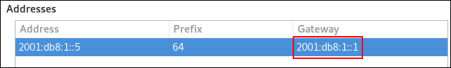
-
Open the
- Click .
- Click .
Restart the network connection for changes to take effect. For example, to restart the
exampleconnection using the command line:# nmcli connection up exampleWarningAll connections currently using this network connection are temporarily interrupted during the restart.
Verification
Verify that the route is active.
To display the IPv4 default gateway:
# ip -4 route default via 192.0.2.1 dev example proto static metric 100
To display the IPv6 default gateway:
# ip -6 route default via 2001:db8:1::1 dev example proto static metric 100 pref medium
Additional resources
25.4. Setting the default gateway on an existing connection by using control-center
In most situations, administrators set the default gateway when they create a connection. However, you can also set or update the default gateway setting on a previously created connection using the control-center application.
Prerequisites
- At least one static IP address must be configured on the connection on which the default gateway will be set.
-
The network configuration of the connection is open in the
control-centerapplication.
Procedure
Set the IPv4 default gateway. For example, to set the IPv4 address of the default gateway on the connection to
192.0.2.1:-
Open the
IPv4tab. Enter the address in the
gatewayfield next to the IP range the gateway’s address is within: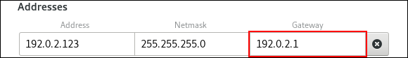
-
Open the
Set the IPv6 default gateway. For example, to set the IPv6 address of the default gateway on the connection to
2001:db8:1::1:-
Open the
IPv6tab. Enter the address in the
gatewayfield next to the IP range the gateway’s address is within:
-
Open the
- Click .
Back in the
Networkwindow, disable and re-enable the connection by switching the button for the connection to and back to for changes to take effect.WarningAll connections currently using this network connection are temporarily interrupted during the restart.
Verification
Verify that the route is active.
To display the IPv4 default gateway:
$ ip -4 route default via 192.0.2.1 dev example proto static metric 100
To display the IPv6 default gateway:
$ ip -6 route default via 2001:db8:1::1 dev example proto static metric 100 pref medium
Additional resources
25.5. Setting the default gateway on an existing connection by using nmstatectl
In most situations, administrators set the default gateway when they create a connection. However, you can also set or update the default gateway setting on a previously created connection by using the nmstatectl utility.
Use the nmstatectl utility to set the default gateway through the Nmstate API. The Nmstate API ensures that, after setting the configuration, the result matches the configuration file. If anything fails, nmstatectl automatically rolls back the changes to avoid leaving the system in an incorrect state.
Prerequisites
- At least one static IP address must be configured on the connection on which the default gateway will be set.
-
The
enp1s0interface is configured, and the IP address of the default gateway is within the subnet of the IP configuration of this interface. -
The
nmstatepackage is installed.
Procedure
Create a YAML file, for example
~/set-default-gateway.yml, with the following content:--- routes: config: - destination: 0.0.0.0/0 next-hop-address: 192.0.2.1 next-hop-interface: enp1s0These settings define
192.0.2.1as the default gateway, and the default gateway is reachable through theenp1s0interface.Apply the settings to the system:
# nmstatectl apply ~/set-default-gateway.yml
Additional resources
-
nmstatectl(8)man page on your system -
/usr/share/doc/nmstate/examples/directory
25.6. Setting the default gateway on an existing connection by using the network RHEL system role
A host forwards a network packet to its default gateway if the packet’s destination can neither be reached through the directly-connected networks nor through any of the routes configured on the host. To configure the default gateway of a host, set it in the NetworkManager connection profile of the interface that is connected to the same network as the default gateway. By using Ansible and the network RHEL system role, you can automate this process and remotely configure connection profiles on the hosts defined in a playbook.
In most situations, administrators set the default gateway when they create a connection. However, you can also set or update the default gateway setting on a previously-created connection.
You cannot use the network RHEL system role to update only specific values in an existing connection profile. The role ensures that a connection profile exactly matches the settings in a playbook. If a connection profile with the same name already exists, the role applies the settings from the playbook and resets all other settings in the profile to their defaults. To prevent resetting values, always specify the whole configuration of the network connection profile in the playbook, including the settings that you do not want to change.
Prerequisites
- You have prepared the control node and the managed nodes
- You are logged in to the control node as a user who can run playbooks on the managed nodes.
-
The account you use to connect to the managed nodes has
sudopermissions on them.
Procedure
Create a playbook file, for example
~/playbook.yml, with the following content:--- - name: Configure the network hosts: managed-node-01.example.com tasks: - name: Ethernet connection profile with static IP address settings ansible.builtin.include_role: name: rhel-system-roles.network vars: network_connections: - name: enp1s0 type: ethernet autoconnect: yes ip: address: - 198.51.100.20/24 - 2001:db8:1::1/64 gateway4: 198.51.100.254 gateway6: 2001:db8:1::fffe dns: - 198.51.100.200 - 2001:db8:1::ffbb dns_search: - example.com state: upFor details about all variables used in the playbook, see the
/usr/share/ansible/roles/rhel-system-roles.network/README.mdfile on the control node.Validate the playbook syntax:
$ ansible-playbook --syntax-check ~/playbook.ymlNote that this command only validates the syntax and does not protect against a wrong but valid configuration.
Run the playbook:
$ ansible-playbook ~/playbook.yml
Verification
Query the Ansible facts of the managed node and verify the active network settings:
# ansible managed-node-01.example.com -m ansible.builtin.setup ... "ansible_default_ipv4": { ... "gateway": "198.51.100.254", "interface": "enp1s0", ... }, "ansible_default_ipv6": { ... "gateway": "2001:db8:1::fffe", "interface": "enp1s0", ... } ...
Additional resources
-
/usr/share/ansible/roles/rhel-system-roles.network/README.mdfile -
/usr/share/doc/rhel-system-roles/network/directory
25.7. How NetworkManager manages multiple default gateways
In certain situations, for example for fallback reasons, you set multiple default gateways on a host. However, to avoid asynchronous routing issues, each default gateway of the same protocol requires a separate metric value. Note that RHEL only uses the connection to the default gateway that has the lowest metric set.
You can set the metric for both the IPv4 and IPv6 gateway of a connection using the following command:
# nmcli connection modify <connection_name> ipv4.route-metric <value> ipv6.route-metric <value>Do not set the same metric value for the same protocol in multiple connection profiles to avoid routing issues.
If you set a default gateway without a metric value, NetworkManager automatically sets the metric value based on the interface type. For that, NetworkManager assigns the default value of this network type to the first connection that is activated, and sets an incremented value to each other connection of the same type in the order they are activated. For example, if two Ethernet connections with a default gateway exist, NetworkManager sets a metric of 100 on the route to the default gateway of the connection that you activate first. For the second connection, NetworkManager sets 101.
The following is an overview of frequently-used network types and their default metrics:
| Connection type | Default metric value |
|---|---|
| VPN | 50 |
| Ethernet | 100 |
| MACsec | 125 |
| InfiniBand | 150 |
| Bond | 300 |
| Team | 350 |
| VLAN | 400 |
| Bridge | 425 |
| TUN | 450 |
| Wi-Fi | 600 |
| IP tunnel | 675 |
Additional resources
25.8. Configuring NetworkManager to avoid using a specific profile to provide a default gateway
You can configure that NetworkManager never uses a specific profile to provide the default gateway. Follow this procedure for connection profiles that are not connected to the default gateway.
Prerequisites
- The NetworkManager connection profile for the connection that is not connected to the default gateway exists.
Procedure
If the connection uses a dynamic IP configuration, configure that NetworkManager does not use this connection as the default connection for the corresponding IP type, meaning that NetworkManager will never assign the default route to it:
# nmcli connection modify <connection_name> ipv4.never-default yes ipv6.never-default yesNote that setting
ipv4.never-defaultandipv6.never-defaulttoyes, automatically removes the default gateway’s IP address for the corresponding protocol from the connection profile.Activate the connection:
# nmcli connection up <connection_name>
Verification
-
Use the
ip -4 routeandip -6 routecommands to verify that RHEL does not use the network interface for the default route for the IPv4 and IPv6 protocol.
25.9. Fixing unexpected routing behavior due to multiple default gateways
There are only a few scenarios, such as when using Multipath TCP, in which you require multiple default gateways on a host. In most cases, you configure only a single default gateway to avoid unexpected routing behavior or asynchronous routing issues.
To route traffic to different internet providers, use policy-based routing instead of multiple default gateways.
Prerequisites
- The host uses NetworkManager to manage network connections, which is the default.
- The host has multiple network interfaces.
- The host has multiple default gateways configured.
Procedure
Display the routing table:
For IPv4, enter:
# ip -4 route default via 192.0.2.1 dev enp1s0 proto static metric 101 default via 198.51.100.1 dev enp7s0 proto static metric 102 ...For IPv6, enter:
# ip -6 route default via 2001:db8:1::1 dev enp1s0 proto static metric 101 pref medium default via 2001:db8:2::1 dev enp7s0 proto static metric 102 pref medium ...
Entries starting with
defaultindicate a default route. Note the interface names of these entries displayed next todev.Use the following commands to display the NetworkManager connections that use the interfaces you identified in the previous step:
# nmcli -f GENERAL.CONNECTION,IP4.GATEWAY,IP6.GATEWAY device show enp1s0 GENERAL.CONNECTION: Corporate-LAN IP4.GATEWAY: 192.0.2.1 IP6.GATEWAY: 2001:db8:1::1 # nmcli -f GENERAL.CONNECTION,IP4.GATEWAY,IP6.GATEWAY device show enp7s0 GENERAL.CONNECTION: Internet-Provider IP4.GATEWAY: 198.51.100.1 IP6.GATEWAY: 2001:db8:2::1
In these examples, the profiles named
Corporate-LANandInternet-Providerhave the default gateways set. Because, in a local network, the default gateway is typically the host that is one hop closer to the internet, the rest of this procedure assumes that the default gateways in theCorporate-LANare incorrect.Configure that NetworkManager does not use the
Corporate-LANconnection as the default route for IPv4 and IPv6 connections:# nmcli connection modify Corporate-LAN ipv4.never-default yes ipv6.never-default yesNote that setting
ipv4.never-defaultandipv6.never-defaulttoyes, automatically removes the default gateway’s IP address for the corresponding protocol from the connection profile.Activate the
Corporate-LANconnection:# nmcli connection up Corporate-LAN
Verification
Display the IPv4 and IPv6 routing tables and verify that only one default gateway is available for each protocol:
For IPv4, enter:
# ip -4 route default via 198.51.100.1 dev enp7s0 proto static metric 102 ...For IPv6, enter:
# ip -6 route default via 2001:db8:2::1 dev enp7s0 proto static metric 102 pref medium ...
Additional resources
Chapter 26. Configuring a static route
Routing ensures that you can send and receive traffic between mutually-connected networks. In larger environments, administrators typically configure services so that routers can dynamically learn about other routers. In smaller environments, administrators often configure static routes to ensure that traffic can reach from one network to the next.
You need static routes to achieve a functioning communication among multiple networks if all of these conditions apply:
- The traffic has to pass multiple networks.
- The exclusive traffic flow through the default gateways is not sufficient.
The Example of a network that requires static routes section describes scenarios and how the traffic flows between different networks when you do not configure static routes.
26.1. Example of a network that requires static routes
You require static routes in this example because not all IP networks are directly connected through one router. Without the static routes, some networks cannot communicate with each other. Additionally, traffic from some networks flows only in one direction.
The network topology in this example is artificial and only used to explain the concept of static routing. It is not a recommended topology in production environments.
For a functioning communication among all networks in this example, configure a static route to Raleigh (198.51.100.0/24) with next the hop Router 2 (203.0.113.10). The IP address of the next hop is the one of Router 2 in the data center network (203.0.113.0/24).
You can configure the static route as follows:
-
For a simplified configuration, set this static route only on Router 1. However, this increases the traffic on Router 1 because hosts from the data center (
203.0.113.0/24) send traffic to Raleigh (198.51.100.0/24) always through Router 1 to Router 2. -
For a more complex configuration, configure this static route on all hosts in the data center (
203.0.113.0/24). All hosts in this subnet then send traffic directly to Router 2 (203.0.113.10) that is closer to Raleigh (198.51.100.0/24).
For more details between which networks traffic flows or not, see the explanations below the diagram.
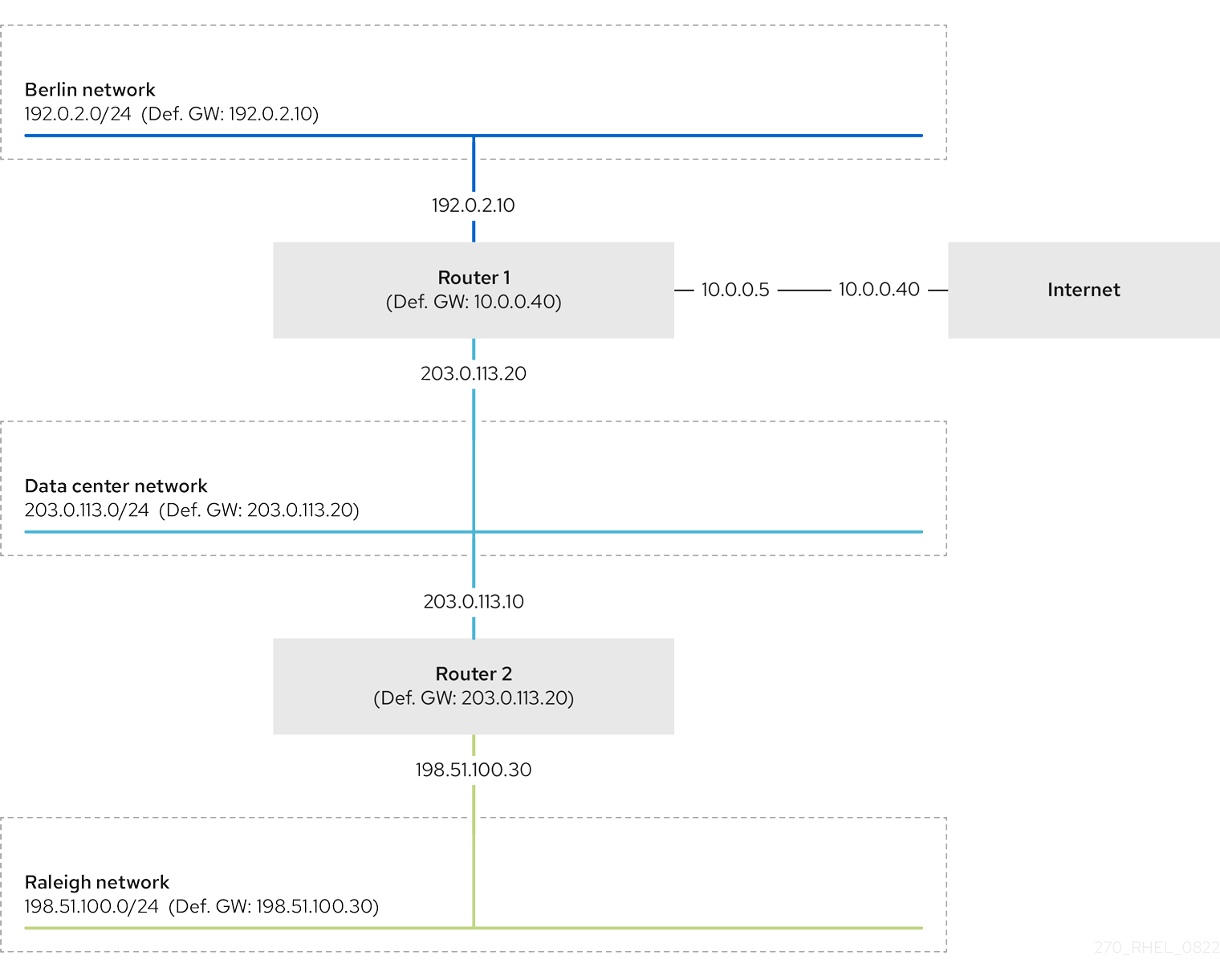
In case that the required static routes are not configured, the following are the situations in which the communication works and when it does not:
Hosts in the Berlin network (
192.0.2.0/24):- Can communicate with other hosts in the same subnet because they are directly connected.
-
Can communicate with the internet because Router 1 is in the Berlin network (
192.0.2.0/24) and has a default gateway, which leads to the internet. -
Can communicate with the data center network (
203.0.113.0/24) because Router 1 has interfaces in both the Berlin (192.0.2.0/24) and the data center (203.0.113.0/24) networks. -
Cannot communicate with the Raleigh network (
198.51.100.0/24) because Router 1 has no interface in this network. Therefore, Router 1 sends the traffic to its own default gateway (internet).
Hosts in the data center network (
203.0.113.0/24):- Can communicate with other hosts in the same subnet because they are directly connected.
-
Can communicate with the internet because they have their default gateway set to Router 1, and Router 1 has interfaces in both networks, the data center (
203.0.113.0/24) and to the internet. -
Can communicate with the Berlin network (
192.0.2.0/24) because they have their default gateway set to Router 1, and Router 1 has interfaces in both the data center (203.0.113.0/24) and the Berlin (192.0.2.0/24) networks. -
Cannot communicate with the Raleigh network (
198.51.100.0/24) because the data center network has no interface in this network. Therefore, hosts in the data center (203.0.113.0/24) send traffic to their default gateway (Router 1). Router 1 also has no interface in the Raleigh network (198.51.100.0/24) and, as a result, Router 1 sends this traffic to its own default gateway (internet).
Hosts in the Raleigh network (
198.51.100.0/24):- Can communicate with other hosts in the same subnet because they are directly connected.
-
Cannot communicate with hosts on the internet. Router 2 sends the traffic to Router 1 because of the default gateway settings. The actual behavior of Router 1 depends on the reverse path filter (
rp_filter) system control (sysctl) setting. By default on RHEL, Router 1 drops the outgoing traffic instead of routing it to the internet. However, regardless of the configured behavior, communication is not possible without the static route. -
Cannot communicate with the data center network (
203.0.113.0/24). The outgoing traffic reaches the destination through Router 2 because of the default gateway setting. However, replies to packets do not reach the sender because hosts in the data center network (203.0.113.0/24) send replies to their default gateway (Router 1). Router 1 then sends the traffic to the internet. -
Cannot communicate with the Berlin network (
192.0.2.0/24). Router 2 sends the traffic to Router 1 because of the default gateway settings. The actual behavior of Router 1 depends on therp_filtersysctlsetting. By default on RHEL, Router 1 drops the outgoing traffic instead of sending it to the Berlin network (192.0.2.0/24). However, regardless of the configured behavior, communication is not possible without the static route.
In addition to configuring the static routes, you must enable IP forwarding on both routers.
Additional resources
- Why cannot a server be pinged if net.ipv4.conf.all.rp_filter is set on the server? (Red Hat Knowledgebase)
- Enabling IP forwarding (Red Hat Knowledgebase)
26.2. How to use the nmcli utility to configure a static route
To configure a static route, use the nmcli utility with the following syntax:
$ nmcli connection modify connection_name ipv4.routes "ip[/prefix] [next_hop] [metric] [attribute=value] [attribute=value] ..."The command supports the following route attributes:
-
cwnd=n: Sets the congestion window (CWND) size, defined in the number of packets. -
lock-cwnd=true|false: Defines whether or not the kernel can update the CWND value. -
lock-mtu=true|false: Defines whether or not the kernel can update the MTU to path MTU discovery. -
lock-window=true|false: Defines whether or not the kernel can update the maximum window size for TCP packets. -
mtu=<mtu_value>: Sets the maximum transfer unit (MTU) to use along the path to the destination. -
onlink=true|false: Defines whether the next hop is directly attached to this link even if it does not match any interface prefix. -
scope=<scope>: For an IPv4 route, this attribute sets the scope of the destinations covered by the route prefix. Set the value as an integer (0-255). -
src=<source_address>: Sets the source address to prefer when sending traffic to the destinations covered by the route prefix. -
table=<table_id>: Sets the ID of the table the route should be added to. If you omit this parameter, NetworkManager uses themaintable. -
tos=<type_of_service_key>: Sets the type of service (TOS) key. Set the value as an integer (0-255). -
type=<route_type>: Sets the route type. NetworkManager supports theunicast,local,blackhole,unreachable,prohibit, andthrowroute types. The default isunicast. -
window=<window_size>: Sets the maximal window size for TCP to advertise to these destinations, measured in bytes.
If you use the ipv4.routes option without a preceding + sign, nmcli overrides all current settings of this parameter.
To create an additional route, enter:
$ nmcli connection modify connection_name +ipv4.routes "<route>"To remove a specific route, enter:
$ nmcli connection modify connection_name -ipv4.routes "<route>"
26.3. Configuring a static route by using nmcli
You can add a static route to an existing NetworkManager connection profile using the nmcli connection modify command.
The procedure below configures the following routes:
-
An IPv4 route to the remote
198.51.100.0/24network. The corresponding gateway with the IP address192.0.2.10is reachable through theLANconnection profile. -
An IPv6 route to the remote
2001:db8:2::/64network. The corresponding gateway with the IP address2001:db8:1::10is reachable through theLANconnection profile.
Prerequisites
-
The
LANconnection profile exists and it configures this host to be in the same IP subnet as the gateways.
Procedure
Add the static IPv4 route to the
LANconnection profile:# nmcli connection modify LAN +ipv4.routes "198.51.100.0/24 192.0.2.10"To set multiple routes in one step, pass the individual routes comma-separated to the command:
# nmcli connection modify <connection_profile> +ipv4.routes "<remote_network_1>/<subnet_mask_1> <gateway_1>, <remote_network_n>/<subnet_mask_n> <gateway_n>, ..."Add the static IPv6 route to the
LANconnection profile:# nmcli connection modify LAN +ipv6.routes "2001:db8:2::/64 2001:db8:1::10"Re-activate the connection:
# nmcli connection up LAN
Verification
Display the IPv4 routes:
# ip -4 route ... 198.51.100.0/24 via 192.0.2.10 dev enp1s0Display the IPv6 routes:
# ip -6 route ... 2001:db8:2::/64 via 2001:db8:1::10 dev enp1s0 metric 1024 pref medium
26.4. Configuring a static route by using nmtui
The nmtui application provides a text-based user interface for NetworkManager. You can use nmtui to configure static routes on a host without a graphical interface.
For example, the procedure below adds a route to the 192.0.2.0/24 network that uses the gateway running on 198.51.100.1, which is reachable through an existing connection profile.
In nmtui:
- Navigate by using the cursor keys.
- Press a button by selecting it and hitting Enter.
- Select and clear checkboxes by using Space.
- To return to the previous screen, use ESC.
Prerequisites
- The network is configured.
- The gateway for the static route must be directly reachable on the interface.
- If the user is logged in on a physical console, user permissions are sufficient. Otherwise, the command requires root permissions.
Procedure
Start
nmtui:# nmtui- Select Edit a connection, and press Enter.
- Select the connection profile through which you can reach the next hop to the destination network, and press Enter.
- Depending on whether it is an IPv4 or IPv6 route, press the Show button next to the protocol’s configuration area.
Press the Edit button next to Routing. This opens a new window where you configure static routes:
Press the Add button and fill in:
- The destination network, including the prefix in Classless Inter-Domain Routing (CIDR) format
- The IP address of the next hop
- A metric value, if you add multiple routes to the same network and want to prioritize the routes by efficiency
- Repeat the previous step for every route you want to add and that is reachable through this connection profile.
Press the OK button to return to the window with the connection settings.
Figure 26.1. Example of a static route without metric

-
Press the OK button to return to the
nmtuimain menu. - Select Activate a connection and press Enter.
Select the connection profile that you edited, and press Enter twice to deactivate and activate it again.
ImportantSkip this step if you run
nmtuiover a remote connection, such as SSH, that uses the connection profile you want to reactivate. In this case, if you deactivate it innmtui, the connection is terminated and, consequently, you cannot activate it again. To avoid this problem, use thenmcli connection <connection_profile> upcommand to reactivate the connection in the mentioned scenario.- Press the Back button to return to the main menu.
-
Select Quit, and press Enter to close the
nmtuiapplication.
Verification
Verify that the route is active:
$ ip route ... 192.0.2.0/24 via 198.51.100.1 dev example proto static metric 100
26.5. Configuring a static route by using control-center
You can use control-center in GNOME to add a static route to the configuration of a network connection.
The procedure below configures the following routes:
-
An IPv4 route to the remote
198.51.100.0/24network. The corresponding gateway has the IP address192.0.2.10. -
An IPv6 route to the remote
2001:db8:2::/64network. The corresponding gateway has the IP address2001:db8:1::10.
Prerequisites
- The network is configured.
- This host is in the same IP subnet as the gateways.
-
The network configuration of the connection is opened in the
control-centerapplication. See Configuring an Ethernet connection by using nm-connection-editor.
Procedure
On the
IPv4tab:-
Optional: Disable automatic routes by clicking the button in the
Routessection of theIPv4tab to use only static routes. If automatic routes are enabled, Red Hat Enterprise Linux uses static routes and routes received from a DHCP server. Enter the address, netmask, gateway, and optionally a metric value of the IPv4 route:
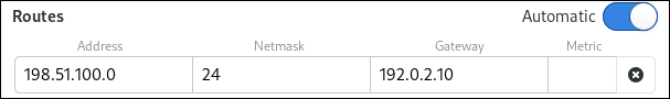
-
Optional: Disable automatic routes by clicking the button in the
On the
IPv6tab:-
Optional: Disable automatic routes by clicking the button i the
Routessection of theIPv4tab to use only static routes. Enter the address, netmask, gateway, and optionally a metric value of the IPv6 route:
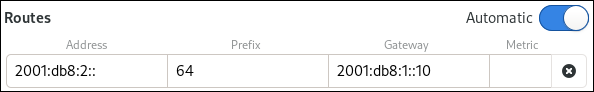
-
Optional: Disable automatic routes by clicking the button i the
- Click .
Back in the
Networkwindow, disable and re-enable the connection by switching the button for the connection to and back to for changes to take effect.WarningRestarting the connection briefly disrupts connectivity on that interface.
Verification
Display the IPv4 routes:
# ip -4 route ... 198.51.100.0/24 via 192.0.2.10 dev enp1s0
Display the IPv6 routes:
# ip -6 route ... 2001:db8:2::/64 via 2001:db8:1::10 dev enp1s0 metric 1024 pref medium
26.6. Configuring a static route by using nm-connection-editor
You can use the nm-connection-editor application to add a static route to the configuration of a network connection.
The procedure below configures the following routes:
-
An IPv4 route to the remote
198.51.100.0/24network. The corresponding gateway with the IP address192.0.2.10is reachable through theexampleconnection. -
An IPv6 route to the remote
2001:db8:2::/64network. The corresponding gateway with the IP address2001:db8:1::10is reachable through theexampleconnection.
Prerequisites
- The network is configured.
- This host is in the same IP subnet as the gateways.
Procedure
Open a terminal, and enter
nm-connection-editor:$ nm-connection-editor-
Select the
exampleconnection profile, and click the gear wheel icon to edit the existing connection. On the
IPv4 Settingstab:- Click the button.
Click the button and enter the address, netmask, gateway, and optionally a metric value.
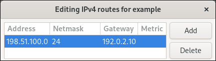
- Click .
On the
IPv6 Settingstab:- Click the button.
Click the button and enter the address, netmask, gateway, and optionally a metric value.
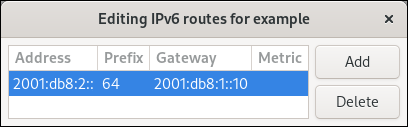
- Click .
- Click .
Restart the network connection for changes to take effect. For example, to restart the
exampleconnection using the command line:# nmcli connection up example
Verification
Display the IPv4 routes:
# ip -4 route ... 198.51.100.0/24 via 192.0.2.10 dev enp1s0
Display the IPv6 routes:
# ip -6 route ... 2001:db8:2::/64 via 2001:db8:1::10 dev enp1s0 metric 1024 pref medium
26.7. Configuring a static route by using the nmcli interactive mode
You can use the interactive mode of the nmcli utility to add a static route to the configuration of a network connection.
The procedure below configures the following routes:
-
An IPv4 route to the remote
198.51.100.0/24network. The corresponding gateway with the IP address192.0.2.10is reachable through theexampleconnection. -
An IPv6 route to the remote
2001:db8:2::/64network. The corresponding gateway with the IP address2001:db8:1::10is reachable through theexampleconnection.
Prerequisites
-
The
exampleconnection profile exists and it configures this host to be in the same IP subnet as the gateways.
Procedure
Open the
nmcliinteractive mode for theexampleconnection:# nmcli connection edit exampleAdd the static IPv4 route:
nmcli> set ipv4.routes 198.51.100.0/24 192.0.2.10Add the static IPv6 route:
nmcli> set ipv6.routes 2001:db8:2::/64 2001:db8:1::10Optional: Verify that the routes were added correctly to the configuration:
nmcli> print ... ipv4.routes: { ip = 198.51.100.0/24, nh = 192.0.2.10 } ... ipv6.routes: { ip = 2001:db8:2::/64, nh = 2001:db8:1::10 } ...
The
ipattribute displays the network to route and thenhattribute the gateway (next hop).Save the configuration:
nmcli> save persistentRestart the network connection:
nmcli> activate exampleLeave the
nmcliinteractive mode:nmcli> quit
Verification
Display the IPv4 routes:
# ip -4 route ... 198.51.100.0/24 via 192.0.2.10 dev enp1s0
Display the IPv6 routes:
# ip -6 route ... 2001:db8:2::/64 via 2001:db8:1::10 dev enp1s0 metric 1024 pref medium
Additional resources
-
nmcli(1)andnm-settings-nmcli(5)man pages on your system
26.8. Configuring a static route by using nmstatectl
Use the nmstatectl utility to configure a static route through the Nmstate API. The Nmstate API ensures that, after setting the configuration, the result matches the configuration file. If anything fails, nmstatectl automatically rolls back the changes to avoid leaving the system in an incorrect state.
Prerequisites
-
The
enp1s0network interface is configured and is in the same IP subnet as the gateways. -
The
nmstatepackage is installed.
Procedure
Create a YAML file, for example
~/add-static-route-to-enp1s0.yml, with the following content:--- routes: config: - destination: 198.51.100.0/24 next-hop-address: 192.0.2.10 next-hop-interface: enp1s0 - destination: 2001:db8:2::/64 next-hop-address: 2001:db8:1::10 next-hop-interface: enp1s0These settings define the following static routes:
-
An IPv4 route to the remote
198.51.100.0/24network. The corresponding gateway with the IP address192.0.2.10is reachable through theenp1s0interface. -
An IPv6 route to the remote
2001:db8:2::/64network. The corresponding gateway with the IP address2001:db8:1::10is reachable through theenp1s0interface.
-
An IPv4 route to the remote
Apply the settings to the system:
# nmstatectl apply ~/add-static-route-to-enp1s0.yml
Verification
Display the IPv4 routes:
# ip -4 route ... 198.51.100.0/24 via 192.0.2.10 dev enp1s0Display the IPv6 routes:
# ip -6 route ... 2001:db8:2::/64 via 2001:db8:1::10 dev enp1s0 metric 1024 pref medium
Additional resources
-
nmstatectl(8)man page on your system -
/usr/share/doc/nmstate/examples/directory
26.9. Configuring a static route by using the network RHEL system role
A static route ensures that you can send traffic to a destination that cannot be reached through the default gateway. You configure static routes in the NetworkManager connection profile of the interface that is connected to the same network as the next hop. By using Ansible and the network RHEL system role, you can automate this process and remotely configure connection profiles on the hosts defined in a playbook.
You cannot use the network RHEL system role to update only specific values in an existing connection profile. The role ensures that a connection profile exactly matches the settings in a playbook. If a connection profile with the same name already exists, the role applies the settings from the playbook and resets all other settings in the profile to their defaults. To prevent resetting values, always specify the whole configuration of the network connection profile in the playbook, including the settings that you do not want to change.
Prerequisites
- You have prepared the control node and the managed nodes
- You are logged in to the control node as a user who can run playbooks on the managed nodes.
-
The account you use to connect to the managed nodes has
sudopermissions on them.
Procedure
Create a playbook file, for example
~/playbook.yml, with the following content:--- - name: Configure the network hosts: managed-node-01.example.com tasks: - name: Ethernet connection profile with static IP address settings ansible.builtin.include_role: name: rhel-system-roles.network vars: network_connections: - name: enp7s0 type: ethernet autoconnect: yes ip: address: - 192.0.2.1/24 - 2001:db8:1::1/64 gateway4: 192.0.2.254 gateway6: 2001:db8:1::fffe dns: - 192.0.2.200 - 2001:db8:1::ffbb dns_search: - example.com route: - network: 198.51.100.0 prefix: 24 gateway: 192.0.2.10 - network: 2001:db8:2:: prefix: 64 gateway: 2001:db8:1::10 state: upFor details about all variables used in the playbook, see the
/usr/share/ansible/roles/rhel-system-roles.network/README.mdfile on the control node.Validate the playbook syntax:
$ ansible-playbook --syntax-check ~/playbook.ymlNote that this command only validates the syntax and does not protect against a wrong but valid configuration.
Run the playbook:
$ ansible-playbook ~/playbook.yml
Verification
Display the IPv4 routes:
# ansible managed-node-01.example.com -m command -a 'ip -4 route' managed-node-01.example.com | CHANGED | rc=0 >> ... 198.51.100.0/24 via 192.0.2.10 dev enp7s0Display the IPv6 routes:
# ansible managed-node-01.example.com -m command -a 'ip -6 route' managed-node-01.example.com | CHANGED | rc=0 >> ... 2001:db8:2::/64 via 2001:db8:1::10 dev enp7s0 metric 1024 pref medium
Additional resources
-
/usr/share/ansible/roles/rhel-system-roles.network/README.mdfile -
/usr/share/doc/rhel-system-roles/network/directory
Chapter 27. Configuring policy-based routing to define alternative routes
By default, the kernel in RHEL decides where to forward network packets based on the destination address using a routing table. Policy-based routing enables you to configure complex routing scenarios. For example, you can route packets based on various criteria, such as the source address, packet metadata, or protocol.
27.1. Routing traffic from a specific subnet to a different default gateway by using nmcli
You can use policy-based routing to configure a different default gateway for traffic from certain subnets. For example, you can configure RHEL as a router that, by default, routes all traffic to internet provider A using the default route. However, traffic received from the internal workstations subnet is routed to provider B.
The procedure assumes the following network topology:
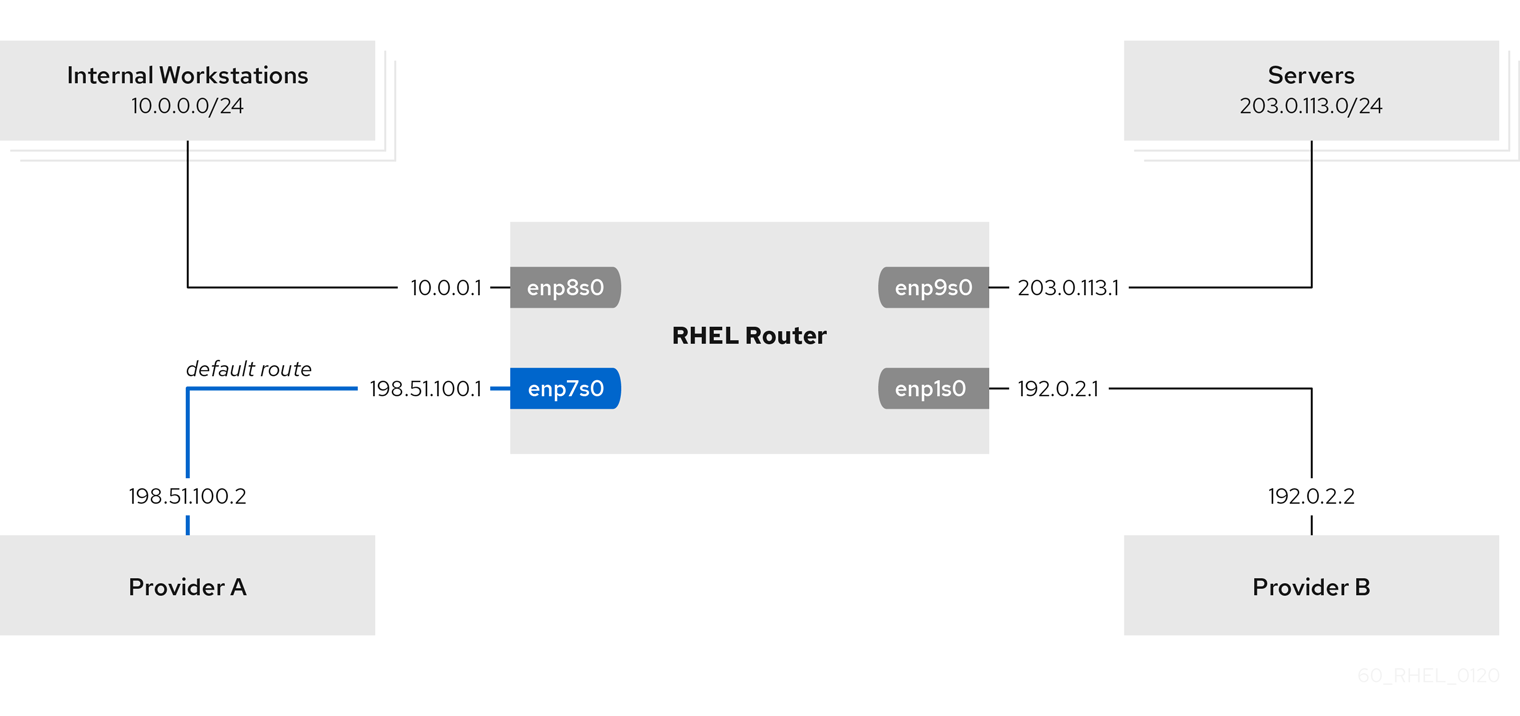
Prerequisites
-
The system uses
NetworkManagerto configure the network, which is the default. The RHEL router you want to set up in the procedure has four network interfaces:
-
The
enp7s0interface is connected to the network of provider A. The gateway IP in the provider’s network is198.51.100.2, and the network uses a/30network mask. -
The
enp1s0interface is connected to the network of provider B. The gateway IP in the provider’s network is192.0.2.2, and the network uses a/30network mask. -
The
enp8s0interface is connected to the10.0.0.0/24subnet with internal workstations. -
The
enp9s0interface is connected to the203.0.113.0/24subnet with the company’s servers.
-
The
-
Hosts in the internal workstations subnet use
10.0.0.1as the default gateway. In the procedure, you assign this IP address to theenp8s0network interface of the router. -
Hosts in the server subnet use
203.0.113.1as the default gateway. In the procedure, you assign this IP address to theenp9s0network interface of the router. -
The
firewalldservice is enabled and active.
Procedure
Configure the network interface to provider A:
# nmcli connection add type ethernet con-name Provider-A ifname enp7s0 ipv4.method manual ipv4.addresses 198.51.100.1/30 ipv4.gateway 198.51.100.2 ipv4.dns 198.51.100.200 connection.zone externalThe
nmcli connection addcommand creates a NetworkManager connection profile. The command uses the following options:-
typeethernet: Defines that the connection type is Ethernet. -
con-name<connection_name>: Sets the name of the profile. Use a meaningful name to avoid confusion. -
ifname<network_device>: Sets the network interface. -
ipv4.methodmanual: Enables to configure a static IP address. -
ipv4.addresses<IP_address>/<subnet_mask>: Sets the IPv4 addresses and subnet mask. -
ipv4.gateway<IP_address>: Sets the default gateway address. -
ipv4.dns<IP_of_DNS_server>: Sets the IPv4 address of the DNS server. -
connection.zone<firewalld_zone>: Assigns the network interface to the definedfirewalldzone. Note thatfirewalldautomatically enables masquerading for interfaces assigned to theexternalzone.
-
Configure the network interface to provider B:
# nmcli connection add type ethernet con-name Provider-B ifname enp1s0 ipv4.method manual ipv4.addresses 192.0.2.1/30 ipv4.routes "0.0.0.0/0 192.0.2.2 table=5000" connection.zone externalThis command uses the
ipv4.routesparameter instead ofipv4.gatewayto set the default gateway. This is required to assign the default gateway for this connection to a different routing table (5000) than the default. NetworkManager automatically creates this new routing table when the connection is activated.Configure the network interface to the internal workstations subnet:
# nmcli connection add type ethernet con-name Internal-Workstations ifname enp8s0 ipv4.method manual ipv4.addresses 10.0.0.1/24 ipv4.routes "10.0.0.0/24 table=5000" ipv4.routing-rules "priority 5 from 10.0.0.0/24 table 5000" connection.zone trustedThis command uses the
ipv4.routesparameter to add a static route to the routing table with ID5000. This static route for the10.0.0.0/24subnet uses the IP of the local network interface to provider B (192.0.2.1) as next hop.Additionally, the command uses the
ipv4.routing-rulesparameter to add a routing rule with priority5that routes traffic from the10.0.0.0/24subnet to table5000. Low values have a high priority.Note that the syntax in the
ipv4.routing-rulesparameter is the same as in anip rule addcommand, except thatipv4.routing-rulesalways requires specifying a priority.Configure the network interface to the server subnet:
# nmcli connection add type ethernet con-name Servers ifname enp9s0 ipv4.method manual ipv4.addresses 203.0.113.1/24 connection.zone trusted
Verification
On a RHEL host in the internal workstation subnet:
Install the
traceroutepackage:# dnf install tracerouteUse the
tracerouteutility to display the route to a host on the internet:# traceroute redhat.com traceroute to redhat.com (209.132.183.105), 30 hops max, 60 byte packets 1 10.0.0.1 (10.0.0.1) 0.337 ms 0.260 ms 0.223 ms 2 192.0.2.1 (192.0.2.1) 0.884 ms 1.066 ms 1.248 ms ...The output of the command displays that the router sends packets over
192.0.2.1, which is the network of provider B.
On a RHEL host in the server subnet:
Install the
traceroutepackage:# dnf install tracerouteUse the
tracerouteutility to display the route to a host on the internet:# traceroute redhat.com traceroute to redhat.com (209.132.183.105), 30 hops max, 60 byte packets 1 203.0.113.1 (203.0.113.1) 2.179 ms 2.073 ms 1.944 ms 2 198.51.100.2 (198.51.100.2) 1.868 ms 1.798 ms 1.549 ms ...The output of the command displays that the router sends packets over
198.51.100.2, which is the network of provider A.
Troubleshooting steps
On the RHEL router:
Display the rule list:
# ip rule list 0: from all lookup local 5: from 10.0.0.0/24 lookup 5000 32766: from all lookup main 32767: from all lookup default
By default, RHEL contains rules for the tables
local,main, anddefault.Display the routes in table
5000:# ip route list table 5000 0.0.0.0/0 via 192.0.2.2 dev enp1s0 proto static metric 100 10.0.0.0/24 dev enp8s0 proto static scope link src 192.0.2.1 metric 102Display the interfaces and firewall zones:
# firewall-cmd --get-active-zones external interfaces: enp1s0 enp7s0 trusted interfaces: enp8s0 enp9s0Verify that the
externalzone has masquerading enabled:# firewall-cmd --info-zone=external external (active) target: default icmp-block-inversion: no interfaces: enp1s0 enp7s0 sources: services: ssh ports: protocols: masquerade: yes ...
Additional resources
-
nmcli(1)andnm-settings(5)man pages on your system
27.2. Routing traffic from a specific subnet to a different default gateway by using the network RHEL system role
You can use policy-based routing to configure a different default gateway for traffic from certain subnets. For example, you can configure RHEL as a router that, by default, routes all traffic to internet provider A using the default route. However, traffic received from the internal workstations subnet is routed to provider B. By using Ansible and the network RHEL system role, you can automate this process and remotely configure connection profiles on the hosts defined in a playbook.
You can use the network RHEL system role to configure the connection profiles, including routing tables and rules.
This procedure assumes the following network topology:
Prerequisites
- You have prepared the control node and the managed nodes
- You are logged in to the control node as a user who can run playbooks on the managed nodes.
-
The account you use to connect to the managed nodes has
sudopermissions on them. -
The managed nodes use NetworkManager and the
firewalldservice. The managed nodes you want to configure has four network interfaces:
-
The
enp7s0interface is connected to the network of provider A. The gateway IP in the provider’s network is198.51.100.2, and the network uses a/30network mask. -
The
enp1s0interface is connected to the network of provider B. The gateway IP in the provider’s network is192.0.2.2, and the network uses a/30network mask. -
The
enp8s0interface is connected to the10.0.0.0/24subnet with internal workstations. -
The
enp9s0interface is connected to the203.0.113.0/24subnet with the company’s servers.
-
The
-
Hosts in the internal workstations subnet use
10.0.0.1as the default gateway. In the procedure, you assign this IP address to theenp8s0network interface of the router. -
Hosts in the server subnet use
203.0.113.1as the default gateway. In the procedure, you assign this IP address to theenp9s0network interface of the router.
Procedure
Create a playbook file, for example
~/playbook.yml, with the following content:--- - name: Configuring policy-based routing hosts: managed-node-01.example.com tasks: - name: Routing traffic from a specific subnet to a different default gateway ansible.builtin.include_role: name: rhel-system-roles.network vars: network_connections: - name: Provider-A interface_name: enp7s0 type: ethernet autoconnect: True ip: address: - 198.51.100.1/30 gateway4: 198.51.100.2 dns: - 198.51.100.200 state: up zone: external - name: Provider-B interface_name: enp1s0 type: ethernet autoconnect: True ip: address: - 192.0.2.1/30 route: - network: 0.0.0.0 prefix: 0 gateway: 192.0.2.2 table: 5000 state: up zone: external - name: Internal-Workstations interface_name: enp8s0 type: ethernet autoconnect: True ip: address: - 10.0.0.1/24 route: - network: 10.0.0.0 prefix: 24 table: 5000 routing_rule: - priority: 5 from: 10.0.0.0/24 table: 5000 state: up zone: trusted - name: Servers interface_name: enp9s0 type: ethernet autoconnect: True ip: address: - 203.0.113.1/24 state: up zone: trustedThe settings specified in the example playbook include the following:
table: <value>-
Assigns the route from the same list entry as the
tablevariable to the specified routing table. routing_rule: <list>- Defines the priority of the specified routing rule and from a connection profile to which routing table the rule is assigned.
zone: <zone_name>-
Assigns the network interface from a connection profile to the specified
firewalldzone.
For details about all variables used in the playbook, see the
/usr/share/ansible/roles/rhel-system-roles.network/README.mdfile on the control node.Validate the playbook syntax:
$ ansible-playbook --syntax-check ~/playbook.ymlNote that this command only validates the syntax and does not protect against a wrong but valid configuration.
Run the playbook:
$ ansible-playbook ~/playbook.yml
Verification
On a RHEL host in the internal workstation subnet:
Install the
traceroutepackage:# dnf install tracerouteUse the
tracerouteutility to display the route to a host on the internet:# traceroute redhat.com traceroute to redhat.com (209.132.183.105), 30 hops max, 60 byte packets 1 10.0.0.1 (10.0.0.1) 0.337 ms 0.260 ms 0.223 ms 2 192.0.2.1 (192.0.2.1) 0.884 ms 1.066 ms 1.248 ms ...The output of the command displays that the router sends packets over
192.0.2.1, which is the network of provider B.
On a RHEL host in the server subnet:
Install the
traceroutepackage:# dnf install tracerouteUse the
tracerouteutility to display the route to a host on the internet:# traceroute redhat.com traceroute to redhat.com (209.132.183.105), 30 hops max, 60 byte packets 1 203.0.113.1 (203.0.113.1) 2.179 ms 2.073 ms 1.944 ms 2 198.51.100.2 (198.51.100.2) 1.868 ms 1.798 ms 1.549 ms ...The output of the command displays that the router sends packets over
198.51.100.2, which is the network of provider A.
On the RHEL router that you configured using the RHEL system role:
Display the rule list:
# ip rule list 0: from all lookup local 5: from 10.0.0.0/24 lookup 5000 32766: from all lookup main 32767: from all lookup default
By default, RHEL contains rules for the tables
local,main, anddefault.Display the routes in table
5000:# ip route list table 5000 0.0.0.0/0 via 192.0.2.2 dev enp1s0 proto static metric 100 10.0.0.0/24 dev enp8s0 proto static scope link src 192.0.2.1 metric 102Display the interfaces and firewall zones:
# firewall-cmd --get-active-zones external interfaces: enp1s0 enp7s0 trusted interfaces: enp8s0 enp9s0Verify that the
externalzone has masquerading enabled:# firewall-cmd --info-zone=external external (active) target: default icmp-block-inversion: no interfaces: enp1s0 enp7s0 sources: services: ssh ports: protocols: masquerade: yes ...
Additional resources
-
/usr/share/ansible/roles/rhel-system-roles.network/README.mdfile -
/usr/share/doc/rhel-system-roles/network/directory
Chapter 28. Reusing the same IP address on different interfaces
With Virtual routing and forwarding (VRF), administrators can use multiple routing tables simultaneously on the same host. For that, VRF partitions a network at layer 3. This enables the administrator to isolate traffic using separate and independent route tables per VRF domain. This technique is similar to virtual LANs (VLAN), which partitions a network at layer 2, where the operating system uses different VLAN tags to isolate traffic sharing the same physical medium.
One benefit of VRF over partitioning on layer 2 is that routing scales better considering the number of peers involved.
Red Hat Enterprise Linux uses a virtual vrt device for each VRF domain and adds routes to a VRF domain by adding existing network devices to a VRF device. Addresses and routes previously attached to the original device will be moved inside the VRF domain.
Note that each VRF domain is isolated from each other.
28.1. Permanently reusing the same IP address on different interfaces
You can use the virtual routing and forwarding (VRF) feature to permanently use the same IP address on different interfaces in one server.
To enable remote peers to contact both VRF interfaces while reusing the same IP address, the network interfaces must belong to different broadcasting domains. A broadcast domain in a network is a set of nodes, which receive broadcast traffic sent by any of them. In most configurations, all nodes connected to the same switch belong to the same broadcasting domain.
Prerequisites
-
You are logged in as the
rootuser. - The network interfaces are not configured.
Procedure
Create and configure the first VRF device:
Create a connection for the VRF device and assign it to a routing table. For example, to create a VRF device named
vrf0that is assigned to the1001routing table:# nmcli connection add type vrf ifname vrf0 con-name vrf0 table 1001 ipv4.method disabled ipv6.method disabledEnable the
vrf0device:# nmcli connection up vrf0Assign a network device to the VRF just created. For example, to add the
enp1s0Ethernet device to thevrf0VRF device and assign an IP address and the subnet mask toenp1s0, enter:# nmcli connection add type ethernet con-name vrf.enp1s0 ifname enp1s0 controller vrf0 ipv4.method manual ipv4.address 192.0.2.1/24Activate the
vrf.enp1s0connection:# nmcli connection up vrf.enp1s0
Create and configure the next VRF device:
Create the VRF device and assign it to a routing table. For example, to create a VRF device named
vrf1that is assigned to the1002routing table, enter:# nmcli connection add type vrf ifname vrf1 con-name vrf1 table 1002 ipv4.method disabled ipv6.method disabledActivate the
vrf1device:# nmcli connection up vrf1Assign a network device to the VRF just created. For example, to add the
enp7s0Ethernet device to thevrf1VRF device and assign an IP address and the subnet mask toenp7s0, enter:# nmcli connection add type ethernet con-name vrf.enp7s0 ifname enp7s0 controller vrf1 ipv4.method manual ipv4.address 192.0.2.1/24Activate the
vrf.enp7s0device:# nmcli connection up vrf.enp7s0
28.2. Temporarily reusing the same IP address on different interfaces
You can use the virtual routing and forwarding (VRF) feature to temporarily use the same IP address on different interfaces in one server. Use this procedure only for testing purposes, because the configuration is temporary and lost after you reboot the system.
To enable remote peers to contact both VRF interfaces while reusing the same IP address, the network interfaces must belong to different broadcasting domains. A broadcast domain in a network is a set of nodes which receive broadcast traffic sent by any of them. In most configurations, all nodes connected to the same switch belong to the same broadcasting domain.
Prerequisites
-
You are logged in as the
rootuser. - The network interfaces are not configured.
Procedure
Create and configure the first VRF device:
Create the VRF device and assign it to a routing table. For example, to create a VRF device named
bluethat is assigned to the1001routing table:# ip link add dev blue type vrf table 1001Enable the
bluedevice:# ip link set dev blue upAssign a network device to the VRF device. For example, to add the
enp1s0Ethernet device to theblueVRF device:# ip link set dev enp1s0 master blueEnable the
enp1s0device:# ip link set dev enp1s0 upAssign an IP address and subnet mask to the
enp1s0device. For example, to set it to192.0.2.1/24:# ip addr add dev enp1s0 192.0.2.1/24
Create and configure the next VRF device:
Create the VRF device and assign it to a routing table. For example, to create a VRF device named
redthat is assigned to the1002routing table:# ip link add dev red type vrf table 1002Enable the
reddevice:# ip link set dev red upAssign a network device to the VRF device. For example, to add the
enp7s0Ethernet device to theredVRF device:# ip link set dev enp7s0 master redEnable the
enp7s0device:# ip link set dev enp7s0 upAssign the same IP address and subnet mask to the
enp7s0device as you used forenp1s0in theblueVRF domain:# ip addr add dev enp7s0 192.0.2.1/24
- Optional: Create further VRF devices as described above.
28.3. Additional resources
-
/usr/share/doc/kernel-doc-<kernel_version>/Documentation/networking/vrf.txtfrom thekernel-docpackage
Chapter 29. Starting a service within an isolated VRF network
With virtual routing and forwarding (VRF), you can create isolated networks with a routing table that is different to the main routing table of the operating system. You can then start services and applications so that they have only access to the network defined in that routing table.
29.1. Configuring a VRF device
To use virtual routing and forwarding (VRF), you create a VRF device and attach a physical or virtual network interface and routing information to it.
To prevent that you lock out yourself out remotely, perform this procedure on the local console or remotely over a network interface that you do not want to assign to the VRF device.
Prerequisites
- You are logged in locally or using a network interface that is different to the one you want to assign to the VRF device.
Procedure
Create the
vrf0connection with a same-named virtual device, and attach it to routing table1000:# nmcli connection add type vrf ifname vrf0 con-name vrf0 table 1000 ipv4.method disabled ipv6.method disabledAdd the
enp1s0device to thevrf0connection, and configure the IP settings:# nmcli connection add type ethernet con-name enp1s0 ifname enp1s0 controller vrf0 ipv4.method manual ipv4.address 192.0.2.1/24 ipv4.gateway 192.0.2.254This command creates the
enp1s0connection as a port of thevrf0connection. Due to this configuration, the routing information are automatically assigned to the routing table1000that is associated with thevrf0device.If you require static routes in the isolated network:
Add the static routes:
# nmcli connection modify enp1s0 +ipv4.routes "198.51.100.0/24 192.0.2.2"This adds a route to the
198.51.100.0/24network that uses192.0.2.2as the router.Activate the connection:
# nmcli connection up enp1s0
Verification
Display the IP settings of the device that is associated with
vrf0:# ip -br addr show vrf vrf0 enp1s0 UP 192.0.2.1/24
Display the VRF devices and their associated routing table:
# ip vrf show Name Table ----------------------- vrf0 1000
Display the main routing table:
# ip route show default via 203.0.113.0/24 dev enp7s0 proto static metric 100
The main routing table does not mention any routes associated with the device
enp1s0device or the192.0.2.1/24subnet.Display the routing table
1000:# ip route show table 1000 default via 192.0.2.254 dev enp1s0 proto static metric 101 broadcast 192.0.2.0 dev enp1s0 proto kernel scope link src 192.0.2.1 192.0.2.0/24 dev enp1s0 proto kernel scope link src 192.0.2.1 metric 101 local 192.0.2.1 dev enp1s0 proto kernel scope host src 192.0.2.1 broadcast 192.0.2.255 dev enp1s0 proto kernel scope link src 192.0.2.1 198.51.100.0/24 via 192.0.2.2 dev enp1s0 proto static metric 101
The
defaultentry indicates that services that use this routing table, use192.0.2.254as their default gateway and not the default gateway in the main routing table.Execute the
tracerouteutility in the network associated withvrf0to verify that the utility uses the route from table1000:# ip vrf exec vrf0 traceroute 203.0.113.1 traceroute to 203.0.113.1 (203.0.113.1), 30 hops max, 60 byte packets 1 192.0.2.254 (192.0.2.254) 0.516 ms 0.459 ms 0.430 ms ...
The first hop is the default gateway that is assigned to the routing table
1000and not the default gateway from the system’s main routing table.
Additional resources
-
ip-vrf(8)man page on your system
29.2. Starting a service within an isolated VRF network
You can configure a service, such as the Apache HTTP Server, to start within an isolated virtual routing and forwarding (VRF) network.
Services can only bind to local IP addresses that are in the same VRF network.
Prerequisites
-
You configured the
vrf0device. -
You configured Apache HTTP Server to listen only on the IP address that is assigned to the interface associated with the
vrf0device.
Procedure
Display the content of the
httpdsystemd service:# systemctl cat httpd ... [Service] ExecStart=/usr/sbin/httpd $OPTIONS -DFOREGROUND ...You require the content of the
ExecStartparameter in a later step to run the same command within the isolated VRF network.Create the
/etc/systemd/system/httpd.service.d/directory:# mkdir /etc/systemd/system/httpd.service.d/Create the
/etc/systemd/system/httpd.service.d/override.conffile with the following content:[Service] ExecStart= ExecStart=/usr/sbin/ip vrf exec vrf0 /usr/sbin/httpd $OPTIONS -DFOREGROUNDTo override the
ExecStartparameter, you first need to unset it and then set it to the new value as shown.Reload systemd.
# systemctl daemon-reloadRestart the
httpdservice.# systemctl restart httpd
Verification
Display the process IDs (PID) of
httpdprocesses:# pidof -c httpd 1904 ...Display the VRF association for the PIDs, for example:
# ip vrf identify 1904 vrf0Display all PIDs associated with the
vrf0device:# ip vrf pids vrf0 1904 httpd ...
Additional resources
-
ip-vrf(8)man page on your system
Chapter 30. Configuring ethtool settings in NetworkManager connection profiles
NetworkManager can configure certain network driver and hardware settings persistently. Compared to using the ethtool utility to manage these settings, this has the benefit of not losing the settings after a reboot.
You can set the following ethtool settings in NetworkManager connection profiles:
- Offload features
- Network interface controllers can use the TCP offload engine (TOE) to offload processing certain operations to the network controller. This improves the network throughput.
- Interrupt coalesce settings
- By using interrupt coalescing, the system collects network packets and generates a single interrupt for multiple packets. This increases the amount of data sent to the kernel with one hardware interrupt, which reduces the interrupt load, and maximizes the throughput.
- Ring buffers
- These buffers store incoming and outgoing network packets. You can increase the ring buffer sizes to reduce a high packet drop rate.
- Channel settings
A network interface manages its associated number of channels along with hardware settings and network drivers. All devices associated with a network interface communicate with each other through interrupt requests (IRQ). Each device queue holds pending IRQ and communicates with each other over a data line known as channel. Types of queues are associated with specific channel types. These channel types include:
-
rxfor receiving queues -
txfor transmit queues -
otherfor link interrupts or single root input/output virtualization (SR-IOV) coordination -
combinedfor hardware capacity-based multipurpose channels
-
30.1. Configuring an ethtool offload feature by using nmcli
You can use NetworkManager to enable and disable ethtool offload features in a connection profile.
Procedure
For example, to enable the RX offload feature and disable TX offload in the
enp1s0connection profile, enter:# nmcli con modify enp1s0 ethtool.feature-rx on ethtool.feature-tx offThis command explicitly enables RX offload and disables TX offload.
To remove the setting of an offload feature that you previously enabled or disabled, set the feature’s parameter to a null value. For example, to remove the configuration for TX offload, enter:
# nmcli con modify enp1s0 ethtool.feature-tx ""Reactivate the network profile:
# nmcli connection up enp1s0
Verification
Use the
ethtool -kcommand to display the current offload features of a network device:# ethtool -k network_device
Additional resources
-
nm-settings-nmcli(5)man page on your system
30.2. Configuring an ethtool offload feature by using the network RHEL system role
Network interface controllers can use the TCP offload engine (TOE) to offload processing certain operations to the network controller. This improves the network throughput. You configure offload features in the connection profile of the network interface. By using Ansible and the network RHEL system role, you can automate this process and remotely configure connection profiles on the hosts defined in a playbook.
You cannot use the network RHEL system role to update only specific values in an existing connection profile. The role ensures that a connection profile exactly matches the settings in a playbook. If a connection profile with the same name already exists, the role applies the settings from the playbook and resets all other settings in the profile to their defaults. To prevent resetting values, always specify the whole configuration of the network connection profile in the playbook, including the settings that you do not want to change.
Prerequisites
- You have prepared the control node and the managed nodes
- You are logged in to the control node as a user who can run playbooks on the managed nodes.
-
The account you use to connect to the managed nodes has
sudopermissions on them.
Procedure
Create a playbook file, for example
~/playbook.yml, with the following content:--- - name: Configure the network hosts: managed-node-01.example.com tasks: - name: Ethernet connection profile with dynamic IP address settings and offload features ansible.builtin.include_role: name: rhel-system-roles.network vars: network_connections: - name: enp1s0 type: ethernet autoconnect: yes ip: dhcp4: yes auto6: yes ethtool: features: gro: no gso: yes tx_sctp_segmentation: no state: upThe settings specified in the example playbook include the following:
gro: no- Disables Generic receive offload (GRO).
gso: yes- Enables Generic segmentation offload (GSO).
tx_sctp_segmentation: no- Disables TX stream control transmission protocol (SCTP) segmentation.
For details about all variables used in the playbook, see the
/usr/share/ansible/roles/rhel-system-roles.network/README.mdfile on the control node.Validate the playbook syntax:
$ ansible-playbook --syntax-check ~/playbook.ymlNote that this command only validates the syntax and does not protect against a wrong but valid configuration.
Run the playbook:
$ ansible-playbook ~/playbook.yml
Verification
Query the Ansible facts of the managed node and verify the offload settings:
# ansible managed-node-01.example.com -m ansible.builtin.setup ... "ansible_enp1s0": { "active": true, "device": "enp1s0", "features": { ... "rx_gro_hw": "off, ... "tx_gso_list": "on, ... "tx_sctp_segmentation": "off", ... } ...
Additional resources
-
/usr/share/ansible/roles/rhel-system-roles.network/README.mdfile -
/usr/share/doc/rhel-system-roles/network/directory
30.3. Configuring an ethtool coalesce settings by using nmcli
You can use NetworkManager to set ethtool coalesce settings in connection profiles.
Procedure
For example, to set the maximum number of received packets to delay to
128in theenp1s0connection profile, enter:# nmcli connection modify enp1s0 ethtool.coalesce-rx-frames 128To remove a coalesce setting, set it to a null value. For example, to remove the
ethtool.coalesce-rx-framessetting, enter:# nmcli connection modify enp1s0 ethtool.coalesce-rx-frames ""To reactivate the network profile:
# nmcli connection up enp1s0
Verification
Use the
ethtool -ccommand to display the current offload features of a network device:# ethtool -c network_device
Additional resources
-
nm-settings-nmcli(5)man page on your system
30.4. Configuring an ethtool coalesce settings by using the network RHEL system role
By using interrupt coalescing, the system collects network packets and generates a single interrupt for multiple packets. This increases the amount of data sent to the kernel with one hardware interrupt, which reduces the interrupt load, and maximizes the throughput. You configure coalesce settings in the connection profile of the network interface. By using Ansible and the network RHEL role, you can automate this process and remotely configure connection profiles on the hosts defined in a playbook.
You cannot use the network RHEL system role to update only specific values in an existing connection profile. The role ensures that a connection profile exactly matches the settings in a playbook. If a connection profile with the same name already exists, the role applies the settings from the playbook and resets all other settings in the profile to their defaults. To prevent resetting values, always specify the whole configuration of the network connection profile in the playbook, including the settings that you do not want to change.
Prerequisites
- You have prepared the control node and the managed nodes
- You are logged in to the control node as a user who can run playbooks on the managed nodes.
-
The account you use to connect to the managed nodes has
sudopermissions on them.
Procedure
Create a playbook file, for example
~/playbook.yml, with the following content:--- - name: Configure the network hosts: managed-node-01.example.com tasks: - name: Ethernet connection profile with dynamic IP address settings and coalesce settings ansible.builtin.include_role: name: rhel-system-roles.network vars: network_connections: - name: enp1s0 type: ethernet autoconnect: yes ip: dhcp4: yes auto6: yes ethtool: coalesce: rx_frames: 128 tx_frames: 128 state: upThe settings specified in the example playbook include the following:
rx_frames: <value>- Sets the number of RX frames.
gso: <value>- Sets the number of TX frames.
For details about all variables used in the playbook, see the
/usr/share/ansible/roles/rhel-system-roles.network/README.mdfile on the control node.Validate the playbook syntax:
$ ansible-playbook --syntax-check ~/playbook.ymlNote that this command only validates the syntax and does not protect against a wrong but valid configuration.
Run the playbook:
$ ansible-playbook ~/playbook.yml
Verification
Display the current offload features of the network device:
# ansible managed-node-01.example.com -m command -a 'ethtool -c enp1s0' managed-node-01.example.com | CHANGED | rc=0 >> ... rx-frames: 128 ... tx-frames: 128 ...
Additional resources
-
/usr/share/ansible/roles/rhel-system-roles.network/README.mdfile -
/usr/share/doc/rhel-system-roles/network/directory
30.5. Increasing the ring buffer size to reduce a high packet drop rate by using nmcli
Increase the size of an Ethernet device’s ring buffers if the packet drop rate causes applications to report a loss of data, timeouts, or other issues.
Receive ring buffers are shared between the device driver and network interface controller (NIC). The card assigns a transmit (TX) and receive (RX) ring buffer. As the name implies, the ring buffer is a circular buffer where an overflow overwrites existing data. There are two ways to move data from the NIC to the kernel, hardware interrupts and software interrupts, also called SoftIRQs.
The kernel uses the RX ring buffer to store incoming packets until the device driver can process them. The device driver drains the RX ring, typically by using SoftIRQs, which puts the incoming packets into a kernel data structure called an sk_buff or skb to begin its journey through the kernel and up to the application that owns the relevant socket.
The kernel uses the TX ring buffer to hold outgoing packets which should be sent to the network. These ring buffers reside at the bottom of the stack and are a crucial point at which packet drop can occur, which in turn will adversely affect network performance.
Procedure
Display the packet drop statistics of the interface:
# ethtool -S enp1s0 ... rx_queue_0_drops: 97326 rx_queue_1_drops: 63783 ...
Note that the output of the command depends on the network card and the driver.
High values in
discardordropcounters indicate that the available buffer fills up faster than the kernel can process the packets. Increasing the ring buffers can help to avoid such loss.Display the maximum ring buffer sizes:
# ethtool -g enp1s0 Ring parameters for enp1s0: Pre-set maximums: RX: 4096 RX Mini: 0 RX Jumbo: 16320 TX: 4096 Current hardware settings: RX: 255 RX Mini: 0 RX Jumbo: 0 TX: 255
If the values in the
Pre-set maximumssection are higher than in theCurrent hardware settingssection, you can change the settings in the next steps.Identify the NetworkManager connection profile that uses the interface:
# nmcli connection show NAME UUID TYPE DEVICE Example-Connection a5eb6490-cc20-3668-81f8-0314a27f3f75 ethernet enp1s0
Update the connection profile, and increase the ring buffers:
To increase the RX ring buffer, enter:
# nmcli connection modify Example-Connection ethtool.ring-rx 4096To increase the TX ring buffer, enter:
# nmcli connection modify Example-Connection ethtool.ring-tx 4096
Reload the NetworkManager connection:
# nmcli connection up Example-ConnectionImportantDepending on the driver your NIC uses, changing in the ring buffer can shortly interrupt the network connection.
Additional resources
- ifconfig and ip commands report packet drops (Red Hat Knowledgebase)
- Should I be concerned about a 0.05% packet drop rate? (Red Hat Knowledgebase)
-
ethtool(8)man page on your system
30.6. Increasing the ring buffer size to reduce a high packet drop rate by using the network RHEL system role
Increase the size of an Ethernet device’s ring buffers if the packet drop rate causes applications to report a loss of data, timeouts, or other issues.
Ring buffers are circular buffers where an overflow overwrites existing data. The network card assigns a transmit (TX) and receive (RX) ring buffer. Receive ring buffers are shared between the device driver and the network interface controller (NIC). Data can move from NIC to the kernel through either hardware interrupts or software interrupts, also called SoftIRQs.
The kernel uses the RX ring buffer to store incoming packets until the device driver can process them. The device driver drains the RX ring, typically by using SoftIRQs, which puts the incoming packets into a kernel data structure called an sk_buff or skb to begin its journey through the kernel and up to the application that owns the relevant socket.
The kernel uses the TX ring buffer to hold outgoing packets which should be sent to the network. These ring buffers reside at the bottom of the stack and are a crucial point at which packet drop can occur, which in turn will adversely affect network performance.
You configure ring buffer settings in the NetworkManager connection profiles. By using Ansible and the network RHEL system role, you can automate this process and remotely configure connection profiles on the hosts defined in a playbook.
You cannot use the network RHEL system role to update only specific values in an existing connection profile. The role ensures that a connection profile exactly matches the settings in a playbook. If a connection profile with the same name already exists, the role applies the settings from the playbook and resets all other settings in the profile to their defaults. To prevent resetting values, always specify the whole configuration of the network connection profile in the playbook, including the settings that you do not want to change.
Prerequisites
- You have prepared the control node and the managed nodes
- You are logged in to the control node as a user who can run playbooks on the managed nodes.
-
The account you use to connect to the managed nodes has
sudopermissions on them. - You know the maximum ring buffer sizes that the device supports.
Procedure
Create a playbook file, for example
~/playbook.yml, with the following content:--- - name: Configure the network hosts: managed-node-01.example.com tasks: - name: Ethernet connection profile with dynamic IP address setting and increased ring buffer sizes ansible.builtin.include_role: name: rhel-system-roles.network vars: network_connections: - name: enp1s0 type: ethernet autoconnect: yes ip: dhcp4: yes auto6: yes ethtool: ring: rx: 4096 tx: 4096 state: upThe settings specified in the example playbook include the following:
rx: <value>- Sets the maximum number of received ring buffer entries.
tx: <value>- Sets the maximum number of transmitted ring buffer entries.
For details about all variables used in the playbook, see the
/usr/share/ansible/roles/rhel-system-roles.network/README.mdfile on the control node.Validate the playbook syntax:
$ ansible-playbook --syntax-check ~/playbook.ymlNote that this command only validates the syntax and does not protect against a wrong but valid configuration.
Run the playbook:
$ ansible-playbook ~/playbook.yml
Verification
Display the maximum ring buffer sizes:
# ansible managed-node-01.example.com -m command -a 'ethtool -g enp1s0' managed-node-01.example.com | CHANGED | rc=0 >> ... Current hardware settings: RX: 4096 RX Mini: 0 RX Jumbo: 0 TX: 4096
Additional resources
-
/usr/share/ansible/roles/rhel-system-roles.network/README.mdfile -
/usr/share/doc/rhel-system-roles/network/directory
30.7. Configuring an ethtool channels settings by using nmcli
By using NetworkManager, you can manage network devices and connections. The ethtool utility manages the link speed and related settings of a network interface card. ethtool handles IRQ based communication with associated devices to manage related channels settings in connection profiles.
Procedure
Display the channels associated with a network device:
# ethtool --show-channels enp1s0 Channel parameters for enp1s0: Pre-set maximums: RX: 4 TX: 3 Other: 10 Combined: 63 Current hardware settings: RX: 1 TX: 1 Other: 1 Combined: 1
Update the channel settings of a network interface:
# nmcli connection modify enp1s0 ethtool.channels-rx 4 ethtool.channels-tx 3 ethtools.channels-other 9 ethtool.channels-combined 50Reactivate the network profile:
# nmcli connection up enp1s0
Verification
Check the updated channel settings associated with the network device:
# ethtool --show-channels enp1s0 Channel parameters for enp1s0: Pre-set maximums: RX: 4 TX: 3 Other: 10 Combined: 63 Current hardware settings: RX: 4 TX: 3 Other: 9 Combined: 50
Additional resources
-
nmcli(5)man page on your system
Chapter 31. Introduction to NetworkManager Debugging
Increasing the log levels for all or certain domains helps to log more details of the operations that NetworkManager performs. You can use this information to troubleshoot problems. NetworkManager provides different levels and domains to produce logging information. The /etc/NetworkManager/NetworkManager.conf file is the main configuration file for NetworkManager. The logs are stored in the journal.
31.1. Introduction to NetworkManager reapply method
The NetworkManager service uses a profile to manage the connection settings of a device. Desktop Bus (D-Bus) API can create, modify, and delete these connection settings. For any changes in a profile, D-Bus API clones the existing settings to the modified settings of a connection. Despite cloning, changes do not apply to the modified settings. To make it effective, reactivate the existing settings of a connection or use the reapply() method.
The reapply() method has the following features:
- Updating modified connection settings without deactivation or restart of a network interface.
-
Removing pending changes from the modified connection settings. As
NetworkManagerdoes not revert the manual changes, you can reconfigure the device and revert external or manual parameters. - Creating different modified connection settings than that of the existing connection settings.
Also, reapply() method supports the following attributes:
-
bridge.ageing-time -
bridge.forward-delay -
bridge.group-address -
bridge.group-forward-mask -
bridge.hello-time -
bridge.max-age -
bridge.multicast-hash-max -
bridge.multicast-last-member-count -
bridge.multicast-last-member-interval -
bridge.multicast-membership-interval -
bridge.multicast-querier -
bridge.multicast-querier-interval -
bridge.multicast-query-interval -
bridge.multicast-query-response-interval -
bridge.multicast-query-use-ifaddr -
bridge.multicast-router -
bridge.multicast-snooping -
bridge.multicast-startup-query-count -
bridge.multicast-startup-query-interval -
bridge.priority -
bridge.stp -
bridge.VLAN-filtering -
bridge.VLAN-protocol -
bridge.VLANs -
802-3-ethernet.accept-all-mac-addresses -
802-3-ethernet.cloned-mac-address -
IPv4.addresses -
IPv4.dhcp-client-id -
IPv4.dhcp-iaid -
IPv4.dhcp-timeout -
IPv4.DNS -
IPv4.DNS-priority -
IPv4.DNS-search -
IPv4.gateway -
IPv4.ignore-auto-DNS -
IPv4.ignore-auto-routes -
IPv4.may-fail -
IPv4.method -
IPv4.never-default -
IPv4.route-table -
IPv4.routes -
IPv4.routing-rules -
IPv6.addr-gen-mode -
IPv6.addresses -
IPv6.dhcp-duid -
IPv6.dhcp-iaid -
IPv6.dhcp-timeout -
IPv6.DNS -
IPv6.DNS-priority -
IPv6.DNS-search -
IPv6.gateway -
IPv6.ignore-auto-DNS -
IPv6.may-fail -
IPv6.method -
IPv6.never-default -
IPv6.ra-timeout -
IPv6.route-metric -
IPv6.route-table -
IPv6.routes -
IPv6.routing-rules
Additional resources
-
nm-settings-nmcli(5)man page on your system
31.2. Setting the NetworkManager log level
By default, all the log domains are set to record the INFO log level. Disable rate-limiting before collecting debug logs. With rate-limiting, systemd-journald drops messages if there are too many of them in a short time. This can occur when the log level is TRACE.
This procedure disables rate-limiting and enables recording debug logs for the all (ALL) domains.
Procedure
To disable rate-limiting, edit the
/etc/systemd/journald.conffile, uncomment theRateLimitBurstparameter in the[Journal]section, and set its value as0:RateLimitBurst=0
Restart the
systemd-journaldservice.# systemctl restart systemd-journaldCreate the
/etc/NetworkManager/conf.d/95-nm-debug.conffile with the following content:[logging] domains=ALL:TRACE
The
domainsparameter can contain multiple comma-separateddomain:levelpairs.Restart the NetworkManager service.
# systemctl restart NetworkManager
Verification
Query the
systemdjournal to display the journal entries of theNetworkManagerunit:# journalctl -u NetworkManager ... Jun 30 15:24:32 server NetworkManager[164187]: <debug> [1656595472.4939] active-connection[0x5565143c80a0]: update activation type from assume to managed Jun 30 15:24:32 server NetworkManager[164187]: <trace> [1656595472.4939] device[55b33c3bdb72840c] (enp1s0): sys-iface-state: assume -> managed Jun 30 15:24:32 server NetworkManager[164187]: <trace> [1656595472.4939] l3cfg[4281fdf43e356454,ifindex=3]: commit type register (type "update", source "device", existing a369f23014b9ede3) -> a369f23014b9ede3 Jun 30 15:24:32 server NetworkManager[164187]: <info> [1656595472.4940] manager: NetworkManager state is now CONNECTED_SITE ...
31.3. Temporarily setting log levels at run time using nmcli
You can change the log level at run time using nmcli.
Procedure
Optional: Display the current logging settings:
# nmcli general logging LEVEL DOMAINS INFO PLATFORM,RFKILL,ETHER,WIFI,BT,MB,DHCP4,DHCP6,PPP,WIFI_SCAN,IP4,IP6,A UTOIP4,DNS,VPN,SHARING,SUPPLICANT,AGENTS,SETTINGS,SUSPEND,CORE,DEVICE,OLPC, WIMAX,INFINIBAND,FIREWALL,ADSL,BOND,VLAN,BRIDGE,DBUS_PROPS,TEAM,CONCHECK,DC B,DISPATCHTo modify the logging level and domains, use the following options:
To set the log level for all domains to the same
LEVEL, enter:# nmcli general logging level LEVEL domains ALLTo change the level for specific domains, enter:
# nmcli general logging level LEVEL domains DOMAINSNote that updating the logging level using this command disables logging for all the other domains.
To change the level of specific domains and preserve the level of all other domains, enter:
# nmcli general logging level KEEP domains DOMAIN:LEVEL,DOMAIN:LEVEL
31.4. Viewing NetworkManager logs
You can view the NetworkManager logs for troubleshooting.
Procedure
To view the logs, enter:
# journalctl -u NetworkManager -b
Additional resources
-
NetworkManager.conf(5)andjournalctl(1)man pages on your system
31.5. Debugging levels and domains
You can use the levels and domains parameters to manage the debugging for NetworkManager. The level defines the verbosity level, whereas the domains define the category of the messages to record the logs with given severity (level).
| Log levels | Description |
|---|---|
|
| Does not log any messages about NetworkManager |
|
| Logs only critical errors |
|
| Logs warnings that can reflect the operation |
|
| Logs various informational messages that are useful for tracking state and operations |
|
| Enables verbose logging for debugging purposes |
|
|
Enables more verbose logging than the |
Note that subsequent levels log all messages from earlier levels. For example, setting the log level to INFO also logs messages contained in the ERR and WARN log level.
Additional resources
-
NetworkManager.conf(5)man page on your system
Chapter 32. Using LLDP to debug network configuration problems
You can use the Link Layer Discovery Protocol (LLDP) to debug network configuration problems in the topology. This means that, LLDP can report configuration inconsistencies with other hosts or routers and switches.
32.1. Debugging an incorrect VLAN configuration using LLDP information
If you configured a switch port to use a certain VLAN and a host does not receive these VLAN packets, you can use the Link Layer Discovery Protocol (LLDP) to debug the problem. Perform this procedure on the host that does not receive the packets.
Prerequisites
-
The
nmstatepackage is installed. - The switch supports LLDP.
- LLDP is enabled on neighbor devices.
Procedure
Create the
~/enable-LLDP-enp1s0.ymlfile with the following content:interfaces: - name: enp1s0 type: ethernet lldp: enabled: trueUse the
~/enable-LLDP-enp1s0.ymlfile to enable LLDP on interfaceenp1s0:# nmstatectl apply ~/enable-LLDP-enp1s0.ymlDisplay the LLDP information:
# nmstatectl show enp1s0 - name: enp1s0 type: ethernet state: up ipv4: enabled: false dhcp: false ipv6: enabled: false autoconf: false dhcp: false lldp: enabled: true neighbors: - - type: 5 system-name: Summit300-48 - type: 6 system-description: Summit300-48 - Version 7.4e.1 (Build 5) 05/27/05 04:53:11 - type: 7 system-capabilities: - MAC Bridge component - Router - type: 1 _description: MAC address chassis-id: 00:01:30:F9:AD:A0 chassis-id-type: 4 - type: 2 _description: Interface name port-id: 1/1 port-id-type: 5 - type: 127 ieee-802-1-vlans: - name: v2-0488-03-0505 vid: 488 oui: 00:80:c2 subtype: 3 - type: 127 ieee-802-3-mac-phy-conf: autoneg: true operational-mau-type: 16 pmd-autoneg-cap: 27648 oui: 00:12:0f subtype: 1 - type: 127 ieee-802-1-ppvids: - 0 oui: 00:80:c2 subtype: 2 - type: 8 management-addresses: - address: 00:01:30:F9:AD:A0 address-subtype: MAC interface-number: 1001 interface-number-subtype: 2 - type: 127 ieee-802-3-max-frame-size: 1522 oui: 00:12:0f subtype: 4 mac-address: 82:75:BE:6F:8C:7A mtu: 1500Verify the output to ensure that the settings match your expected configuration. For example, the LLDP information of the interface connected to the switch shows that the switch port this host is connected to uses VLAN ID
448:- type: 127 ieee-802-1-vlans: - name: v2-0488-03-0505 vid: 488If the network configuration of the
enp1s0interface uses a different VLAN ID, change it accordingly.
Additional resources
Chapter 33. Linux traffic control
Linux offers tools for managing and manipulating the transmission of packets. The Linux Traffic Control (TC) subsystem helps in policing, classifying, shaping, and scheduling network traffic. TC also mangles the packet content during classification by using filters and actions. The TC subsystem achieves this by using queuing disciplines (qdisc), a fundamental element of the TC architecture.
The scheduling mechanism arranges or rearranges the packets before they enter or exit different queues. The most common scheduler is the First-In-First-Out (FIFO) scheduler. You can do the qdiscs operations temporarily using the tc utility or permanently using NetworkManager.
In Red Hat Enterprise Linux, you can configure default queueing disciplines in various ways to manage the traffic on a network interface.
33.1. Overview of queuing disciplines
Queuing disciplines (qdiscs) help with queuing up and, later, scheduling of traffic transmission by a network interface. A qdisc has two operations;
- enqueue requests so that a packet can be queued up for later transmission and
- dequeue requests so that one of the queued-up packets can be chosen for immediate transmission.
Every qdisc has a 16-bit hexadecimal identification number called a handle, with an attached colon, such as 1: or abcd:. This number is called the qdisc major number. If a qdisc has classes, then the identifiers are formed as a pair of two numbers with the major number before the minor, <major>:<minor>, for example abcd:1. The numbering scheme for the minor numbers depends on the qdisc type. Sometimes the numbering is systematic, where the first-class has the ID <major>:1, the second one <major>:2, and so on. Some qdiscs allow the user to set class minor numbers arbitrarily when creating the class.
- Classful
qdiscs Different types of
qdiscsexist and help in the transfer of packets to and from a networking interface. You can configureqdiscswith root, parent, or child classes. The point where children can be attached are called classes. Classes inqdiscare flexible and can always contain either multiple children classes or a single child,qdisc. There is no prohibition against a class containing a classfulqdiscitself, this facilitates complex traffic control scenarios.Classful
qdiscsdo not store any packets themselves. Instead, they enqueue and dequeue requests down to one of their children according to criteria specific to theqdisc. Eventually, this recursive packet passing ends up where the packets are stored (or picked up from in the case of dequeuing).- Classless
qdiscs -
Some
qdiscscontain no child classes and they are called classlessqdiscs. Classlessqdiscsrequire less customization compared to classfulqdiscs. It is usually enough to attach them to an interface.
Additional resources
-
tc(8)andtc-actions(8)man pages on your system
33.2. Introduction to connection tracking
At a firewall, the Netfilter framework filters packets from an external network. After a packet arrives, Netfilter assigns a connection tracking entry. Connection tracking is a Linux kernel networking feature for logical networks that tracks connections and identifies packet flow in those connections. This feature filters and analyzes every packet, sets up the connection tracking table to store connection status, and updates the connection status based on identified packets. For example, in the case of FTP connection, Netfilter assigns a connection tracking entry to ensure all packets of FTP connection work in the same manner. The connection tracking entry stores a Netfilter mark and tracks the connection state information in the memory table in which a new packet tuple maps with an existing entry. If the packet tuple does not map with an existing entry, the packet adds a new connection tracking entry that groups packets of the same connection.
You can control and analyze traffic on the network interface. The tc traffic controller utility uses the qdisc discipline to configure the packet scheduler in the network. The qdisc kernel-configured queuing discipline enqueues packets to the interface. By using qdisc, Kernel catches all the traffic before a network interface transmits it. Also, to limit the bandwidth rate of packets belonging to the same connection, use the tc qdisc command.
To retrieve data from connection tracking marks into various fields, use the tc utility with the ctinfo module and the connmark functionality. For storing packet mark information, the ctinfo module copies the Netfilter mark and the connection state information into a socket buffer (skb) mark metadata field.
Transmitting a packet over a physical medium removes all the metadata of a packet. Before the packet loses its metadata, the ctinfo module maps and copies the Netfilter mark value to a specific value of the Diffserv code point (DSCP) in the packet’s IP field.
Additional resources
-
tc(8)andtc-ctinfo(8)man pages on your system
33.3. Inspecting qdiscs of a network interface using the tc utility
By default, Red Hat Enterprise Linux systems use fq_codel qdisc. You can inspect the qdisc counters using the tc utility.
Procedure
Optional: View your current
qdisc:# tc qdisc show dev enp0s1Inspect the current
qdisccounters:# tc -s qdisc show dev enp0s1 qdisc fq_codel 0: root refcnt 2 limit 10240p flows 1024 quantum 1514 target 5.0ms interval 100.0ms memory_limit 32Mb ecn Sent 1008193 bytes 5559 pkt (dropped 233, overlimits 55 requeues 77) backlog 0b 0p requeues 0-
dropped- the number of times a packet is dropped because all queues are full -
overlimits- the number of times the configured link capacity is filled -
sent- the number of dequeues
-
33.4. Updating the default qdisc
If you observe networking packet losses with the current qdisc, you can change the qdisc based on your network-requirements.
Procedure
View the current default
qdisc:# sysctl -a | grep qdisc net.core.default_qdisc = fq_codelView the
qdiscof current Ethernet connection:# tc -s qdisc show dev enp0s1 qdisc fq_codel 0: root refcnt 2 limit 10240p flows 1024 quantum 1514 target 5.0ms interval 100.0ms memory_limit 32Mb ecn Sent 0 bytes 0 pkt (dropped 0, overlimits 0 requeues 0) backlog 0b 0p requeues 0 maxpacket 0 drop_overlimit 0 new_flow_count 0 ecn_mark 0 new_flows_len 0 old_flows_len 0Update the existing
qdisc:# sysctl -w net.core.default_qdisc=pfifo_fastTo apply the changes, reload the network driver:
# modprobe -r NETWORKDRIVERNAME # modprobe NETWORKDRIVERNAME
Start the network interface:
# ip link set enp0s1 up
Verification
View the
qdiscof the Ethernet connection:# tc -s qdisc show dev enp0s1 qdisc pfifo_fast 0: root refcnt 2 bands 3 priomap 1 2 2 2 1 2 0 0 1 1 1 1 1 1 1 1 Sent 373186 bytes 5333 pkt (dropped 0, overlimits 0 requeues 0) backlog 0b 0p requeues 0 ....
Additional resources
-
How to set
sysctlvariables on Red Hat Enterprise Linux (Red Hat Knowledgebase)
33.5. Temporarily setting the current qdisc of a network interface using the tc utility
You can update the current qdisc without changing the default one.
Procedure
Optional: View the current
qdisc:# tc -s qdisc show dev enp0s1Update the current
qdisc:# tc qdisc replace dev enp0s1 root htb
Verification
View the updated current
qdisc:# tc -s qdisc show dev enp0s1 qdisc htb 8001: root refcnt 2 r2q 10 default 0 direct_packets_stat 0 direct_qlen 1000 Sent 0 bytes 0 pkt (dropped 0, overlimits 0 requeues 0) backlog 0b 0p requeues 0
33.6. Permanently setting the current qdisc of a network interface using NetworkManager
You can update the current qdisc value of a NetworkManager connection.
Procedure
Optional: View the current
qdisc:# tc qdisc show dev enp0s1 qdisc fq_codel 0: root refcnt 2Update the current
qdisc:# nmcli connection modify enp0s1 tc.qdiscs 'root pfifo_fast'Optional: To add another
qdiscover the existingqdisc, use the+tc.qdiscoption:# nmcli connection modify enp0s1 +tc.qdisc 'ingress handle ffff:'Activate the changes:
# nmcli connection up enp0s1
Verification
View current
qdiscthe network interface:# tc qdisc show dev enp0s1 qdisc pfifo_fast 8001: root refcnt 2 bands 3 priomap 1 2 2 2 1 2 0 0 1 1 1 1 1 1 1 1 qdisc ingress ffff: parent ffff:fff1 ----------------
Additional resources
-
nm-settings(5)man page on your system
33.7. Configuring the rate limiting of packets by using the tc-ctinfo utility
You can limit network traffic and prevent the exhaustion of resources in the network by using rate limiting. With rate limiting, you can also reduce the load on servers by limiting repetitive packet requests in a specific time frame. In addition, you can manage bandwidth rate by configuring traffic control in the kernel with the tc-ctinfo utility.
The connection tracking entry stores the Netfilter mark and connection information. When a router forwards a packet from the firewall, the router either removes or modifies the connection tracking entry from the packet. The connection tracking information (ctinfo) module retrieves data from connection tracking marks into various fields. This kernel module preserves the Netfilter mark by copying it into a socket buffer (skb) mark metadata field.
Prerequisites
-
The
iperf3utility is installed on a server and a client.
Procedure
Perform the following steps on the server:
Add a virtual link to the network interface:
# ip link add name ifb4eth0 numtxqueues 48 numrxqueues 48 type ifbThis command has the following parameters:
name ifb4eth0- Sets a new virtual device interface.
numtxqueues 48- Sets the number of transmit queues.
numrxqueues 48- Sets the number of receive queues.
type ifb- Sets the type of the new device.
Change the state of the interface:
# ip link set dev ifb4eth0 upAdd the
qdiscattribute on the physical network interface and apply it to the incoming traffic:# tc qdisc add dev enp1s0 handle ffff: ingressIn the
handle ffff:option, thehandleparameter assigns the major numberffff:as a default value to a classfulqdiscon theenp1s0physical network interface, whereqdiscis a queueing discipline parameter to analyze traffic control.Add a filter on the physical interface of the
ipprotocol to classify packets:# tc filter add dev enp1s0 parent ffff: protocol ip u32 match u32 0 0 action ctinfo cpmark 100 action mirred egress redirect dev ifb4eth0This command has the following attributes:
parent ffff:-
Sets major number
ffff:for the parentqdisc. u32 match u32 0 0-
Sets the
u32filter tomatchthe IP headers the ofu32pattern. The first0represents the second byte of IP header while the other0is for the mask match telling the filter which bits to match. action ctinfo- Sets action to retrieve data from the connection tracking mark into various fields.
cpmark 100-
Copies the connection tracking mark (connmark)
100into the packet IP header field. action mirred egress redirect dev ifb4eth0-
Sets
actionmirredto redirect the received packets to theifb4eth0destination interface.
Add a classful
qdiscto the interface:# tc qdisc add dev ifb4eth0 root handle 1: htb default 1000This command sets the major number
1to rootqdiscand uses thehtbhierarchy token bucket with classfulqdiscof minor-id1000.Limit the traffic on the interface to 1 Mbit/s with an upper limit of 2 Mbit/s:
# tc class add dev ifb4eth0 parent 1:1 classid 1:100 htb ceil 2mbit rate 1mbit prio 100This command has the following parameters:
parent 1:1-
Sets
parentwithclassidas1androotas1. classid 1:100-
Sets
classidas1:100where1is the number of parentqdiscand100is the number of classes of the parentqdisc. htb ceil 2mbit-
The
htbclassfulqdiscallows upper limit bandwidth of2 Mbit/sas theceilrate limit.
Apply the Stochastic Fairness Queuing (
sfq) of classlessqdiscto interface with a time interval of60seconds to reduce queue algorithm perturbation:# tc qdisc add dev ifb4eth0 parent 1:100 sfq perturb 60Add the firewall mark (
fw) filter to the interface:# tc filter add dev ifb4eth0 parent 1:0 protocol ip prio 100 handle 100 fw classid 1:100Restore the packet meta mark from the connection mark (
CONNMARK):# nft add rule ip mangle PREROUTING counter meta mark set ct markIn this command, the
nftutility has amangletable with thePREROUTINGchain rule specification that alters incoming packets before routing to replace the packet mark withCONNMARK.If no
nfttable and chain exist, create a table and add a chain rule:# nft add table ip mangle # nft add chain ip mangle PREROUTING {type filter hook prerouting priority mangle \;}
Set the meta mark on
tcppackets that are received on the specified destination address192.0.2.3:# nft add rule ip mangle PREROUTING ip daddr 192.0.2.3 counter meta mark set 0x64Save the packet mark into the connection mark:
# nft add rule ip mangle PREROUTING counter ct mark set markRun the
iperf3utility as the server on a system by using the-sparameter and the server then waits for the response of the client connection:# iperf3 -s
On the client, run
iperf3as a client and connect to the server that listens on IP address192.0.2.3for periodic HTTP request-response timestamp:# iperf3 -c 192.0.2.3 -t TCP_STREAM | tee rate192.0.2.3is the IP address of the server while192.0.2.4is the IP address of the client.Terminate the
iperf3utility on the server by pressing Ctrl+C:Accepted connection from 192.0.2.4, port 52128 [5] local 192.0.2.3 port 5201 connected to 192.0.2.4 port 52130 [ID] Interval Transfer Bitrate [5] 0.00-1.00 sec 119 KBytes 973 Kbits/sec [5] 1.00-2.00 sec 116 KBytes 950 Kbits/sec ... [ID] Interval Transfer Bitrate [5] 0.00-14.81 sec 1.51 MBytes 853 Kbits/sec receiver iperf3: interrupt - the server has terminated
Terminate the
iperf3utility on the client by pressing Ctrl+C:Connecting to host 192.0.2.3, port 5201 [5] local 192.0.2.4 port 52130 connected to 192.0.2.3 port 5201 [ID] Interval Transfer Bitrate Retr Cwnd [5] 0.00-1.00 sec 481 KBytes 3.94 Mbits/sec 0 76.4 KBytes [5] 1.00-2.00 sec 223 KBytes 1.83 Mbits/sec 0 82.0 KBytes ... [ID] Interval Transfer Bitrate Retr [5] 0.00-14.00 sec 3.92 MBytes 2.35 Mbits/sec 32 sender [5] 0.00-14.00 sec 0.00 Bytes 0.00 bits/sec receiver iperf3: error - the server has terminated
Verification
Display the statistics about packet counts of the
htbandsfqclasses on the interface:# tc -s qdisc show dev ifb4eth0 qdisc htb 1: root ... Sent 26611455 bytes 3054 pkt (dropped 76, overlimits 4887 requeues 0) ... qdisc sfq 8001: parent ... Sent 26535030 bytes 2296 pkt (dropped 76, overlimits 0 requeues 0) ...Display the statistics of packet counts for the
mirredandctinfoactions:# tc -s filter show dev enp1s0 ingress filter parent ffff: protocol ip pref 49152 u32 chain 0 filter parent ffff: protocol ip pref 49152 u32 chain 0 fh 800: ht divisor 1 filter parent ffff: protocol ip pref 49152 u32 chain 0 fh 800::800 order 2048 key ht 800 bkt 0 terminal flowid not_in_hw (rule hit 8075 success 8075) match 00000000/00000000 at 0 (success 8075 ) action order 1: ctinfo zone 0 pipe index 1 ref 1 bind 1 cpmark 0x00000064 installed 3105 sec firstused 3105 sec DSCP set 0 error 0 CPMARK set 7712 Action statistics: Sent 25891504 bytes 3137 pkt (dropped 0, overlimits 0 requeues 0) backlog 0b 0p requeues 0 action order 2: mirred (Egress Redirect to device ifb4eth0) stolen index 1 ref 1 bind 1 installed 3105 sec firstused 3105 sec Action statistics: Sent 25891504 bytes 3137 pkt (dropped 0, overlimits 61 requeues 0) backlog 0b 0p requeues 0Display the statistics of the
htbrate-limiter and its configuration:# tc -s class show dev ifb4eth0 class htb 1:100 root leaf 8001: prio 7 rate 1Mbit ceil 2Mbit burst 1600b cburst 1600b Sent 26541716 bytes 2373 pkt (dropped 61, overlimits 4887 requeues 0) backlog 0b 0p requeues 0 lended: 7248 borrowed: 0 giants: 0 tokens: 187250 ctokens: 93625
Additional resources
-
tc(8)andtc-ctinfo(8)man page on your system -
nft(8)man page on your system
33.8. Available qdiscs in RHEL
Each qdisc addresses unique networking-related issues. The following is the list of qdiscs available in RHEL. You can use any of the following qdisc to shape network traffic based on your networking requirements.
qdisc name | Included in | Offload support |
|---|---|---|
| Credit-Based Shaper |
| Yes |
| CHOose and Keep for responsive flows, CHOose and Kill for unresponsive flows (CHOKE) |
| |
| Controlled Delay (CoDel) |
| |
| Enhanced Transmission Selection (ETS) |
| Yes |
| Fair Queue (FQ) |
| |
| Fair Queuing Controlled Delay (FQ_CODel) |
| |
| Generalized Random Early Detection (GRED) |
| |
| Hierarchical Fair Service Curve (HSFC) |
| |
| Heavy-Hitter Filter (HHF) |
| |
| Hierarchy Token Bucket (HTB) |
| Yes |
| INGRESS |
| Yes |
| Multi Queue Priority (MQPRIO) |
| Yes |
| Multiqueue (MULTIQ) |
| Yes |
| Network Emulator (NETEM) |
| |
| Proportional Integral-controller Enhanced (PIE) |
| |
| PLUG |
| |
| Quick Fair Queueing (QFQ) |
| |
| Random Early Detection (RED) |
| Yes |
| Stochastic Fair Blue (SFB) |
| |
| Stochastic Fairness Queueing (SFQ) |
| |
| Token Bucket Filter (TBF) |
| Yes |
| Trivial Link Equalizer (TEQL) |
|
The qdisc offload requires hardware and driver support on NIC.
Additional resources
-
tc(8)man page on your system
Chapter 34. Authenticating a RHEL client to the network by using the 802.1X standard with a certificate stored on the file system
Administrators frequently use port-based Network Access Control (NAC) based on the IEEE 802.1X standard to protect a network from unauthorized LAN and Wi-Fi clients. If the network uses the Extensible Authentication Protocol Transport Layer Security (EAP-TLS) mechanism, you require a certificate to authenticate the client to this network.
34.1. Configuring 802.1X network authentication on an existing Ethernet connection by using nmcli
You can use the nmcli utility to configure an Ethernet connection with 802.1X network authentication on the command line.
Prerequisites
- The network supports 802.1X network authentication.
- The Ethernet connection profile exists in NetworkManager and has a valid IP configuration.
The following files required for TLS authentication exist on the client:
-
The client key stored is in the
/etc/pki/tls/private/client.keyfile, and the file is owned and only readable by therootuser. -
The client certificate is stored in the
/etc/pki/tls/certs/client.crtfile. -
The Certificate Authority (CA) certificate is stored in the
/etc/pki/tls/certs/ca.crtfile.
-
The client key stored is in the
-
The
wpa_supplicantpackage is installed.
Procedure
Set the Extensible Authentication Protocol (EAP) to
tlsand the paths to the client certificate and key file:# nmcli connection modify enp1s0 802-1x.eap tls 802-1x.client-cert /etc/pki/tls/certs/client.crt 802-1x.private-key /etc/pki/tls/certs/certs/client.keyNote that you must set the
802-1x.eap,802-1x.client-cert, and802-1x.private-keyparameters in a single command.Set the path to the CA certificate:
# nmcli connection modify enp1s0 802-1x.ca-cert /etc/pki/tls/certs/ca.crtSet the identity of the user used in the certificate:
# nmcli connection modify enp1s0 802-1x.identity user@example.comOptional: Store the password in the configuration:
# nmcli connection modify enp1s0 802-1x.private-key-password passwordImportantBy default, NetworkManager stores the password in clear text in the connection profile on the disk, but the file is readable only by the
rootuser. However, clear text passwords in a configuration file can be a security risk.To increase the security, set the
802-1x.password-flagsparameter toagent-owned. With this setting, on servers with the GNOME desktop environment or thenm-appletrunning, NetworkManager retrieves the password from these services, after you unlock the keyring. In other cases, NetworkManager prompts for the password.Activate the connection profile:
# nmcli connection up enp1s0
Verification
- Access resources on the network that require network authentication.
Additional resources
34.2. Configuring a static Ethernet connection with 802.1X network authentication by using nmstatectl
Use the nmstatectl utility to configure an Ethernet connection with 802.1X network authentication through the Nmstate API. The Nmstate API ensures that, after setting the configuration, the result matches the configuration file. If anything fails, nmstatectl automatically rolls back the changes to avoid leaving the system in an incorrect state.
The nmstate library only supports the TLS Extensible Authentication Protocol (EAP) method.
Prerequisites
- The network supports 802.1X network authentication.
- The managed node uses NetworkManager.
The following files required for TLS authentication exist on the client:
-
The client key stored is in the
/etc/pki/tls/private/client.keyfile, and the file is owned and only readable by therootuser. -
The client certificate is stored in the
/etc/pki/tls/certs/client.crtfile. -
The Certificate Authority (CA) certificate is stored in the
/etc/pki/tls/certs/ca.crtfile.
-
The client key stored is in the
Procedure
Create a YAML file, for example
~/create-ethernet-profile.yml, with the following content:--- interfaces: - name: enp1s0 type: ethernet state: up ipv4: enabled: true address: - ip: 192.0.2.1 prefix-length: 24 dhcp: false ipv6: enabled: true address: - ip: 2001:db8:1::1 prefix-length: 64 autoconf: false dhcp: false 802.1x: ca-cert: /etc/pki/tls/certs/ca.crt client-cert: /etc/pki/tls/certs/client.crt eap-methods: - tls identity: client.example.org private-key: /etc/pki/tls/private/client.key private-key-password: password routes: config: - destination: 0.0.0.0/0 next-hop-address: 192.0.2.254 next-hop-interface: enp1s0 - destination: ::/0 next-hop-address: 2001:db8:1::fffe next-hop-interface: enp1s0 dns-resolver: config: search: - example.com server: - 192.0.2.200 - 2001:db8:1::ffbbThese settings define an Ethernet connection profile for the
enp1s0device with the following settings:-
A static IPv4 address -
192.0.2.1with a/24subnet mask -
A static IPv6 address -
2001:db8:1::1with a/64subnet mask -
An IPv4 default gateway -
192.0.2.254 -
An IPv6 default gateway -
2001:db8:1::fffe -
An IPv4 DNS server -
192.0.2.200 -
An IPv6 DNS server -
2001:db8:1::ffbb -
A DNS search domain -
example.com -
802.1X network authentication using the
TLSEAP protocol
-
A static IPv4 address -
Apply the settings to the system:
# nmstatectl apply ~/create-ethernet-profile.yml
Verification
- Access resources on the network that require network authentication.
34.3. Configuring a static Ethernet connection with 802.1X network authentication by using the network RHEL system role
Network Access Control (NAC) protects a network from unauthorized clients. You can specify the details that are required for the authentication in NetworkManager connection profiles to enable clients to access the network. By using Ansible and the network RHEL system role, you can automate this process and remotely configure connection profiles on the hosts defined in a playbook.
You can use an Ansible playbook to copy a private key, a certificate, and the CA certificate to the client, and then use the network RHEL system role to configure a connection profile with 802.1X network authentication.
Prerequisites
- You have prepared the control node and the managed nodes
- You are logged in to the control node as a user who can run playbooks on the managed nodes.
-
The account you use to connect to the managed nodes has
sudopermissions on them. - The network supports 802.1X network authentication.
- The managed nodes use NetworkManager.
The following files required for the TLS authentication exist on the control node:
-
The client key is stored in the
/srv/data/client.keyfile. -
The client certificate is stored in the
/srv/data/client.crtfile. -
The Certificate Authority (CA) certificate is stored in the
/srv/data/ca.crtfile.
-
The client key is stored in the
Procedure
Store your sensitive variables in an encrypted file:
Create the vault:
$ ansible-vault create vault.yml New Vault password: <vault_password> Confirm New Vault password: <vault_password>
After the
ansible-vault createcommand opens an editor, enter the sensitive data in the<key>: <value>format:pwd: <password>- Save the changes, and close the editor. Ansible encrypts the data in the vault.
Create a playbook file, for example
~/playbook.yml, with the following content:--- - name: Configure an Ethernet connection with 802.1X authentication hosts: managed-node-01.example.com vars_files: - vault.yml tasks: - name: Copy client key for 802.1X authentication ansible.builtin.copy: src: "/srv/data/client.key" dest: "/etc/pki/tls/private/client.key" mode: 0600 - name: Copy client certificate for 802.1X authentication ansible.builtin.copy: src: "/srv/data/client.crt" dest: "/etc/pki/tls/certs/client.crt" - name: Copy CA certificate for 802.1X authentication ansible.builtin.copy: src: "/srv/data/ca.crt" dest: "/etc/pki/ca-trust/source/anchors/ca.crt" - name: Ethernet connection profile with static IP address settings and 802.1X ansible.builtin.include_role: name: rhel-system-roles.network vars: network_connections: - name: enp1s0 type: ethernet autoconnect: yes ip: address: - 192.0.2.1/24 - 2001:db8:1::1/64 gateway4: 192.0.2.254 gateway6: 2001:db8:1::fffe dns: - 192.0.2.200 - 2001:db8:1::ffbb dns_search: - example.com ieee802_1x: identity: <user_name> eap: tls private_key: "/etc/pki/tls/private/client.key" private_key_password: "{{ pwd }}" client_cert: "/etc/pki/tls/certs/client.crt" ca_cert: "/etc/pki/ca-trust/source/anchors/ca.crt" domain_suffix_match: example.com state: upThe settings specified in the example playbook include the following:
ieee802_1x- This variable contains the 802.1X-related settings.
eap: tls-
Configures the profile to use the certificate-based
TLSauthentication method for the Extensible Authentication Protocol (EAP).
For details about all variables used in the playbook, see the
/usr/share/ansible/roles/rhel-system-roles.network/README.mdfile on the control node.Validate the playbook syntax:
$ ansible-playbook --ask-vault-pass --syntax-check ~/playbook.ymlNote that this command only validates the syntax and does not protect against a wrong but valid configuration.
Run the playbook:
$ ansible-playbook --ask-vault-pass ~/playbook.yml
Verification
- Access resources on the network that require network authentication.
Additional resources
-
/usr/share/ansible/roles/rhel-system-roles.network/README.mdfile -
/usr/share/doc/rhel-system-roles/network/directory - Ansible vault
34.4. Configuring a wifi connection with 802.1X network authentication by using the network RHEL system role
Network Access Control (NAC) protects a network from unauthorized clients. You can specify the details that are required for the authentication in NetworkManager connection profiles to enable clients to access the network. By using Ansible and the network RHEL system role, you can automate this process and remotely configure connection profiles on the hosts defined in a playbook.
You can use an Ansible playbook to copy a private key, a certificate, and the CA certificate to the client, and then use the network RHEL system role to configure a connection profile with 802.1X network authentication.
Prerequisites
- You have prepared the control node and the managed nodes
- You are logged in to the control node as a user who can run playbooks on the managed nodes.
-
The account you use to connect to the managed nodes has
sudopermissions on them. - The network supports 802.1X network authentication.
-
You installed the
wpa_supplicantpackage on the managed node. - DHCP is available in the network of the managed node.
The following files required for TLS authentication exist on the control node:
-
The client key is stored in the
/srv/data/client.keyfile. -
The client certificate is stored in the
/srv/data/client.crtfile. -
The CA certificate is stored in the
/srv/data/ca.crtfile.
-
The client key is stored in the
Procedure
Store your sensitive variables in an encrypted file:
Create the vault:
$ ansible-vault create vault.yml New Vault password: <vault_password> Confirm New Vault password: <vault_password>
After the
ansible-vault createcommand opens an editor, enter the sensitive data in the<key>: <value>format:pwd: <password>- Save the changes, and close the editor. Ansible encrypts the data in the vault.
Create a playbook file, for example
~/playbook.yml, with the following content:--- - name: Configure a wifi connection with 802.1X authentication hosts: managed-node-01.example.com tasks: - name: Copy client key for 802.1X authentication ansible.builtin.copy: src: "/srv/data/client.key" dest: "/etc/pki/tls/private/client.key" mode: 0400 - name: Copy client certificate for 802.1X authentication ansible.builtin.copy: src: "/srv/data/client.crt" dest: "/etc/pki/tls/certs/client.crt" - name: Copy CA certificate for 802.1X authentication ansible.builtin.copy: src: "/srv/data/ca.crt" dest: "/etc/pki/ca-trust/source/anchors/ca.crt" - name: Wifi connection profile with dynamic IP address settings and 802.1X ansible.builtin.import_role: name: rhel-system-roles.network vars: network_connections: - name: Wifi connection profile with dynamic IP address settings and 802.1X interface_name: wlp1s0 state: up type: wireless autoconnect: yes ip: dhcp4: true auto6: true wireless: ssid: "Example-wifi" key_mgmt: "wpa-eap" ieee802_1x: identity: <user_name> eap: tls private_key: "/etc/pki/tls/client.key" private_key_password: "{{ pwd }}" private_key_password_flags: none client_cert: "/etc/pki/tls/client.pem" ca_cert: "/etc/pki/tls/cacert.pem" domain_suffix_match: "example.com"The settings specified in the example playbook include the following:
ieee802_1x- This variable contains the 802.1X-related settings.
eap: tls-
Configures the profile to use the certificate-based
TLSauthentication method for the Extensible Authentication Protocol (EAP).
For details about all variables used in the playbook, see the
/usr/share/ansible/roles/rhel-system-roles.network/README.mdfile on the control node.Validate the playbook syntax:
$ ansible-playbook --ask-vault-pass --syntax-check ~/playbook.ymlNote that this command only validates the syntax and does not protect against a wrong but valid configuration.
Run the playbook:
$ ansible-playbook --ask-vault-pass ~/playbook.yml
Additional resources
-
/usr/share/ansible/roles/rhel-system-roles.network/README.mdfile -
/usr/share/doc/rhel-system-roles/network/directory
Chapter 35. Setting up an 802.1x network authentication service for LAN clients by using hostapd with FreeRADIUS backend
The IEEE 802.1X standard defines secure authentication and authorization methods to protect networks from unauthorized clients. By using the hostapd service and FreeRADIUS, you can provide network access control (NAC) in your network.
Red Hat supports only FreeRADIUS with Red Hat Identity Management (IdM) as the backend source of authentication.
In this documentation, the RHEL host acts as a bridge to connect different clients with an existing network. However, the RHEL host grants only authenticated clients access to the network.

35.1. Prerequisites
A clean installation of the
freeradiusandfreeradius-ldappackages.If the packages are already installed, remove the
/etc/raddb/directory, uninstall and then install the packages again. Do not reinstall the packages by using thednf reinstallcommand, because the permissions and symbolic links in the/etc/raddb/directory are then different.- The host on which you want to configure FreeRADIUS is a client in an IdM domain.
35.2. Setting up the bridge on the authenticator
A network bridge is a link-layer device which forwards traffic between hosts and networks based on a table of MAC addresses. If you set up RHEL as an 802.1X authenticator, add both the interfaces on which to perform authentication and the LAN interface to the bridge.
Prerequisites
- The server has multiple Ethernet interfaces.
Procedure
If the bridge interface does not exist, create it:
# nmcli connection add type bridge con-name br0 ifname br0Assign the Ethernet interfaces to the bridge:
# nmcli connection add type ethernet port-type bridge con-name br0-port1 ifname enp1s0 controller br0 # nmcli connection add type ethernet port-type bridge con-name br0-port2 ifname enp7s0 controller br0 # nmcli connection add type ethernet port-type bridge con-name br0-port3 ifname enp8s0 controller br0 # nmcli connection add type ethernet port-type bridge con-name br0-port4 ifname enp9s0 controller br0
Enable the bridge to forward extensible authentication protocol over LAN (EAPOL) packets:
# nmcli connection modify br0 group-forward-mask 8Configure the connection to automatically activate the ports:
# nmcli connection modify br0 connection.autoconnect-ports 1Activate the connection:
# nmcli connection up br0
Verification
Display the link status of Ethernet devices that are ports of a specific bridge:
# ip link show master br0 3: enp1s0: <BROADCAST,MULTICAST,UP,LOWER_UP> mtu 1500 qdisc fq_codel master br0 state UP mode DEFAULT group default qlen 1000 link/ether 52:54:00:62:61:0e brd ff:ff:ff:ff:ff:ff ...Verify if forwarding of EAPOL packets is enabled on the
br0device:# cat /sys/class/net/br0/bridge/group_fwd_mask 0x8If the command returns
0x8, forwarding is enabled.
Additional resources
-
nm-settings(5)man page on your system
35.3. Configuring FreeRADIUS to authenticate network clients securely by using EAP
FreeRADIUS supports different methods of the Extensible authentication protocol (EAP). However, for a supported and secure scenario, use EAP-TTLS (tunneled transport layer security).
With EAP-TTLS, the clients use a secure TLS connection as the outer authentication protocol to set up the tunnel. The inner authentication then uses LDAP to authenticate to Identity Management. To use EAP-TTLS, you need a TLS server certificate.
The default FreeRADIUS configuration files serve as documentation and describe all parameters and directives. If you want to disable certain features, comment them out instead of removing the corresponding parts in the configuration files. This enables you to preserve the structure of the configuration files and the included documentation.
Prerequisites
-
You installed the
freeradiusandfreeradius-ldappackages. -
The configuration files in the
/etc/raddb/directory are unchanged and as provided by thefreeradiuspackages. - The host is enrolled in a Red Hat Enterprise Linux Identity Management (IdM) domain.
Procedure
Create a private key and request a certificate from IdM:
# ipa-getcert request -w -k /etc/pki/tls/private/radius.key -f /etc/pki/tls/certs/radius.pem -o "root:radiusd" -m 640 -O "root:radiusd" -M 640 -T caIPAserviceCert -C 'systemctl restart radiusd.service' -N freeradius.idm.example.com -D freeradius.idm.example.com -K radius/freeradius.idm.example.comThe
certmongerservice stores the private key in the/etc/pki/tls/private/radius.keyfile and the certificate in the/etc/pki/tls/certs/radius.pemfile, and it sets secure permissions. Additionally,certmongerwill monitor the certificate, renew it before it expires, and restart theradiusdservice after the certificate was renewed.Verify that the CA successfully issued the certificate:
# ipa-getcert list -f /etc/pki/tls/certs/radius.pem ... Number of certificates and requests being tracked: 1. Request ID '20240918142211': status: MONITORING stuck: no key pair storage: type=FILE,location='/etc/pki/tls/private/radius.key' certificate: type=FILE,location='/etc/pki/tls/certs/radius.crt' ...Create the
/etc/raddb/certs/dhfile with Diffie-Hellman (DH) parameters. For example, to create a DH file with a 2048 bits prime, enter:# openssl dhparam -out /etc/raddb/certs/dh 2048For security reasons, do not use a DH file with less than a 2048 bits prime. Depending on the number of bits, the creation of the file can take several minutes.
Edit the
/etc/raddb/mods-available/eapfile:Configure the TLS-related settings in the
tls-config tls-commondirective:eap { ... tls-config tls-common { ... private_key_file = /etc/pki/tls/private/radius.key certificate_file = /etc/pki/tls/certs/radius.pem ca_file = /etc/ipa/ca.crt ... } }Set the
default_eap_typeparameter in theeapdirective tottls:eap { ... default_eap_type = ttls ... }Comment out the
md5directives to disable the insecure EAP-MD5 authentication method:eap { ... # md5 { # } ... }Note that, in the default configuration file, other insecure EAP authentication methods are commented out by default.
Edit the
/etc/raddb/sites-available/defaultfile, and comment out all authentication methods other thaneap:authenticate { ... # Auth-Type PAP { # pap # } # Auth-Type CHAP { # chap # } # Auth-Type MS-CHAP { # mschap # } # mschap # digest ... }This leaves only EAP enabled for the outer authentication and disables plain-text authentication methods.
Edit the
/etc/raddb/sites-available/inner-tunnelfile, and make the following changes:Comment out the
-ldapentry and add theldapmodule configuration to theauthorizedirective:authorize { ... #-ldap ldap if ((ok || updated) && User-Password) { update { control:Auth-Type := ldap } } ... }Uncomment the LDAP authentication type in the
authenticatedirective:authenticate { Auth-Type LDAP { ldap } }
Enable the
ldapmodule:# ln -s /etc/raddb/mods-available/ldap /etc/raddb/mods-enabled/ldapEdit the
/etc/raddb/mods-available/ldapfile, and make the following changes:In the
ldapdirective, set the IdM LDAP server URL and the base distinguished name (DN):ldap { ... server = 'ldaps://idm_server.idm.example.com' base_dn = 'cn=users,cn=accounts,dc=idm,dc=example,dc=com' ... }Specify the
ldapsprotocol in the server URL to use TLS-encrypted connections between the FreeRADIUS host and the IdM server.In the
ldapdirective, enable TLS certificate validation of the IdM LDAP server:tls { ... require_cert = 'demand' ... }
Edit the
/etc/raddb/clients.conffile:Set a secure password in the
localhostandlocalhost_ipv6client directives:client localhost { ipaddr = 127.0.0.1 ... secret = localhost_client_password ... } client localhost_ipv6 { ipv6addr = ::1 secret = localhost_client_password }Add a client directive for the network authenticator:
client hostapd.example.org { ipaddr = 192.0.2.2/32 secret = hostapd_client_password }
Optional: If other hosts should also be able to access the FreeRADIUS service, add client directives for them as well, for example:
client <hostname_or_description> { ipaddr = <IP_address_or_range> secret = <client_password> }
The
ipaddrparameter accepts IPv4 and IPv6 addresses, and you can use the optional classless inter-domain routing (CIDR) notation to specify ranges. However, you can set only one value in this parameter. For example, to grant access to both an IPv4 and IPv6 address, you must add two client directives.Use a descriptive name for the client directive, such as a hostname or a word that describes where the IP range is used.
Verify the configuration files:
# radiusd -XC ... Configuration appears to be OKOpen the RADIUS ports in the
firewalldservice:# firewall-cmd --permanent --add-service=radius # firewall-cmd --reload
Enable and start the
radiusdservice:# systemctl enable --now radiusd
Troubleshooting
If the
radiusdservice fails to start, verify that you can resolve the IdM server host name:# host -v idm_server.idm.example.comFor other problems, run
radiusdin debug mode:Stop the
radiusdservice:# systemctl stop radiusdStart the service in debug mode:
# radiusd -X ... Ready to process requests-
Perform authentication tests on the FreeRADIUS host, as referenced in the
Verificationsection.
Next steps
- Disable no longer required authentication methods and other features you do not use.
35.4. Configuring hostapd as an authenticator in a wired network
The host access point daemon (hostapd) service can act as an authenticator in a wired network to provide 802.1X authentication. For this, the hostapd service requires a RADIUS server that authenticates the clients.
The hostapd service provides an integrated RADIUS server. However, use the integrated RADIUS server only for testing purposes. For production environments, use FreeRADIUS server, which supports additional features, such as different authentication methods and access control.
The hostapd service does not interact with the traffic plane. The service acts only as an authenticator. For example, use a script or service that uses the hostapd control interface to allow or deny traffic based on the result of authentication events.
Prerequisites
-
You installed the
hostapdpackage. - The FreeRADIUS server has been configured, and it is ready to authenticate clients.
Procedure
Create the
/etc/hostapd/hostapd.conffile with the following content:# General settings of hostapd # =========================== # Control interface settings ctrl_interface=/var/run/hostapd ctrl_interface_group=wheel # Enable logging for all modules logger_syslog=-1 logger_stdout=-1 # Log level logger_syslog_level=2 logger_stdout_level=2 # Wired 802.1X authentication # =========================== # Driver interface type driver=wired # Enable IEEE 802.1X authorization ieee8021x=1 # Use port access entry (PAE) group address # (01:80:c2:00:00:03) when sending EAPOL frames use_pae_group_addr=1 # Network interface for authentication requests interface=br0 # RADIUS client configuration # =========================== # Local IP address used as NAS-IP-Address own_ip_addr=192.0.2.2 # Unique NAS-Identifier within scope of RADIUS server nas_identifier=hostapd.example.org # RADIUS authentication server auth_server_addr=192.0.2.1 auth_server_port=1812 auth_server_shared_secret=hostapd_client_password # RADIUS accounting server acct_server_addr=192.0.2.1 acct_server_port=1813 acct_server_shared_secret=hostapd_client_password
For further details about the parameters used in this configuration, see their descriptions in the
/usr/share/doc/hostapd/hostapd.confexample configuration file.Enable and start the
hostapdservice:# systemctl enable --now hostapd
Troubleshooting
If the
hostapdservice fails to start, verify that the bridge interface you use in the/etc/hostapd/hostapd.conffile is present on the system:# ip link show br0For other problems, run
hostapdin debug mode:Stop the
hostapdservice:# systemctl stop hostapdStart the service in debug mode:
# hostapd -d /etc/hostapd/hostapd.conf-
Perform authentication tests on the FreeRADIUS host, as referenced in the
Verificationsection.
Additional resources
-
hostapd.conf(5)man page on your system -
/usr/share/doc/hostapd/hostapd.conffile
35.5. Testing EAP-TTLS authentication against a FreeRADIUS server or authenticator
To test if authentication by using extensible authentication protocol (EAP) over tunneled transport layer security (EAP-TTLS) works as expected, run this procedure:
- After you set up the FreeRADIUS server
-
After you set up the
hostapdservice as an authenticator for 802.1X network authentication.
The output of the test utilities used in this procedure provide additional information about the EAP communication and help you to debug problems.
Prerequisites
When you want to authenticate to:
A FreeRADIUS server:
-
The
eapol_testutility, provided by thehostapdpackage, is installed. - The client, on which you run this procedure, has been authorized in the FreeRADIUS server’s client databases.
-
The
-
An authenticator, the
wpa_supplicantutility, provided by the same-named package, is installed.
-
You stored the certificate authority (CA) certificate in the
/etc/ipa/ca.certfile.
Procedure
Optional: Create a user in Identity Management (IdM):
# ipa user-add --first "Test" --last "User" idm_user --passwordCreate the
/etc/wpa_supplicant/wpa_supplicant-TTLS.conffile with the following content:ap_scan=0 network={ eap=TTLS eapol_flags=0 key_mgmt=IEEE8021X # Anonymous identity (sent in unencrypted phase 1) # Can be any string anonymous_identity="anonymous" # Inner authentication (sent in TLS-encrypted phase 2) phase2="auth=PAP" identity="idm_user" password="idm_user_password" # CA certificate to validate the RADIUS server's identity ca_cert="/etc/ipa/ca.crt" }To authenticate to:
A FreeRADIUS server, enter:
# eapol_test -c /etc/wpa_supplicant/wpa_supplicant-TTLS.conf -a 192.0.2.1 -s <client_password> ... EAP: Status notification: remote certificate verification (param=success) ... CTRL-EVENT-EAP-SUCCESS EAP authentication completed successfully ... SUCCESSThe
-aoption defines the IP address of the FreeRADIUS server, and the-soption specifies the password for the host on which you run the command in the FreeRADIUS server’s client configuration.An authenticator, enter:
# wpa_supplicant -c /etc/wpa_supplicant/wpa_supplicant-TTLS.conf -D wired -i enp0s31f6 ... enp0s31f6: CTRL-EVENT-EAP-SUCCESS EAP authentication completed successfully ...The
-ioption specifies the network interface name on whichwpa_supplicantsends out extended authentication protocol over LAN (EAPOL) packets.For more debugging information, pass the
-doption to the command.
Additional resources
-
/usr/share/doc/wpa_supplicant/wpa_supplicant.conffile
35.6. Blocking and allowing traffic based on hostapd authentication events
The hostapd service does not interact with the traffic plane. The service acts only as an authenticator. However, you can write a script to allow and deny traffic based on the result of authentication events.
This procedure is not supported and is no enterprise-ready solution. It only demonstrates how to block or allow traffic by evaluating events retrieved by hostapd_cli.
When the 802-1x-tr-mgmt systemd service starts, RHEL blocks all traffic on the listen port of hostapd except extensible authentication protocol over LAN (EAPOL) packets and uses the hostapd_cli utility to connect to the hostapd control interface. The /usr/local/bin/802-1x-tr-mgmt script then evaluates events. Depending on the different events received by hostapd_cli, the script allows or blocks traffic for MAC addresses. Note that, when the 802-1x-tr-mgmt service stops, all traffic is automatically allowed again.
Perform this procedure on the hostapd server.
Prerequisites
-
The
hostapdservice has been configured, and the service is ready to authenticate clients.
Procedure
Create the
/usr/local/bin/802-1x-tr-mgmtfile with the following content:#!/bin/sh TABLE="tr-mgmt-${1}" read -r -d '' TABLE_DEF << EOF table bridge ${TABLE} { set allowed_macs { type ether_addr } chain accesscontrol { ether saddr @allowed_macs accept ether daddr @allowed_macs accept drop } chain forward { type filter hook forward priority 0; policy accept; meta ibrname "br0" jump accesscontrol } } EOF case ${2:-NOTANEVENT} in block_all) nft destroy table bridge "$TABLE" printf "$TABLE_DEF" | nft -f - echo "$1: All the bridge traffic blocked. Traffic for a client with a given MAC will be allowed after 802.1x authentication" ;; AP-STA-CONNECTED | CTRL-EVENT-EAP-SUCCESS | CTRL-EVENT-EAP-SUCCESS2) nft add element bridge tr-mgmt-br0 allowed_macs { $3 } echo "$1: Allowed traffic from $3" ;; AP-STA-DISCONNECTED | CTRL-EVENT-EAP-FAILURE) nft delete element bridge tr-mgmt-br0 allowed_macs { $3 } echo "$1: Denied traffic from $3" ;; allow_all) nft destroy table bridge "$TABLE" echo "$1: Allowed all bridge traffice again" ;; NOTANEVENT) echo "$0 was called incorrectly, usage: $0 interface event [mac_address]" ;; esacCreate the
/etc/systemd/system/802-1x-tr-mgmt@.servicesystemd service file with the following content:[Unit] Description=Example 802.1x traffic management for hostapd After=hostapd.service After=sys-devices-virtual-net-%i.device [Service] Type=simple ExecStartPre=bash -c '/usr/sbin/hostapd_cli ping | grep PONG' ExecStartPre=/usr/local/bin/802-1x-tr-mgmt %i block_all ExecStart=/usr/sbin/hostapd_cli -i %i -a /usr/local/bin/802-1x-tr-mgmt ExecStopPost=/usr/local/bin/802-1x-tr-mgmt %i allow_all [Install] WantedBy=multi-user.target
Reload systemd:
# systemctl daemon-reloadEnable and start the
802-1x-tr-mgmtservice with the interface namehostapdis listening on:# systemctl enable --now 802-1x-tr-mgmt@br0.service
Verification
- Authenticate with a client to the network. See Testing EAP-TTLS authentication against a FreeRADIUS server or authenticator.
Additional resources
-
systemd.service(5)man page on your system
Chapter 36. Getting started with Multipath TCP
Transmission Control Protocol (TCP) ensures reliable delivery of the data through the internet and automatically adjusts its bandwidth in response to network load. Multipath TCP (MPTCP) is an extension to the original TCP protocol (single-path). MPTCP enables a transport connection to operate across multiple paths simultaneously, and brings network connection redundancy to user endpoint devices.
36.1. Understanding MPTCP
The Multipath TCP (MPTCP) protocol allows for simultaneous usage of multiple paths between connection endpoints. The protocol design improves connection stability and also brings other benefits compared to the single-path TCP.
In MPTCP terminology, links are considered as paths.
The following are some of the advantages of using MPTCP:
- It allows a connection to simultaneously use multiple network interfaces.
- In case a connection is bound to a link speed, the usage of multiple links can increase the connection throughput. Note, that in case of the connection is bound to a CPU, the usage of multiple links causes the connection slowdown.
- It increases the resilience to link failures.
For more details about MPTCP, review the Additional resources.
36.2. Preparing RHEL to enable MPTCP support
By default the MPTCP support is disabled in RHEL. Enable MPTCP so that applications that support this feature can use it. Additionally, you have to configure user space applications to force use MPTCP sockets if those applications have TCP sockets by default.
Prerequisites
The following packages are installed:
-
iperf3 -
mptcpd -
systemtap
Procedure
Enable MPTCP sockets in the kernel:
# echo "net.mptcp.enabled=1" > /etc/sysctl.d/90-enable-MPTCP.conf # sysctl -p /etc/sysctl.d/90-enable-MPTCP.conf
Start the
iperf3server, and force it to create MPTCP sockets instead of TCP sockets:# mptcpize run iperf3 -s Server listening on 5201Connect the client to the server, and force it to create MPTCP sockets instead of TCP sockets:
# mptcpize iperf3 -c 127.0.0.1 -t 3After the connection is established, verify the
ssoutput to see the subflow-specific status:# ss -nti '( dport :5201 )' State Recv-Q Send-Q Local Address:Port Peer Address:Port Process ESTAB 0 0 127.0.0.1:41842 127.0.0.1:5201 cubic wscale:7,7 rto:205 rtt:4.455/8.878 ato:40 mss:21888 pmtu:65535 rcvmss:536 advmss:65483 cwnd:10 bytes_sent:141 bytes_acked:142 bytes_received:4 segs_out:8 segs_in:7 data_segs_out:3 data_segs_in:3 send 393050505bps lastsnd:2813 lastrcv:2772 lastack:2772 pacing_rate 785946640bps delivery_rate 10944000000bps delivered:4 busy:41ms rcv_space:43690 rcv_ssthresh:43690 minrtt:0.008 tcp-ulp-mptcp flags:Mmec token:0000(id:0)/2ff053ec(id:0) seq:3e2cbea12d7673d4 sfseq:3 ssnoff:ad3d00f4 maplen:2Verify MPTCP counters:
# nstat MPTcp* #kernel MPTcpExtMPCapableSYNRX 2 0.0 MPTcpExtMPCapableSYNTX 2 0.0 MPTcpExtMPCapableSYNACKRX 2 0.0 MPTcpExtMPCapableACKRX 2 0.0
Additional resources
-
tcp(7)andmptcpize(8)man pages on your system
36.3. Using iproute2 to temporarily configure and enable multiple paths for MPTCP applications
Each MPTCP connection uses a single subflow similar to plain TCP. To get the MPTCP benefits, specify a higher limit for maximum number of subflows for each MPTCP connection. Then configure additional endpoints to create those subflows.
The configuration in this procedure will not persist after rebooting your machine.
Note that MPTCP does not yet support mixed IPv6 and IPv4 endpoints for the same socket. Use endpoints belonging to the same address family.
Prerequisites
-
The
mptcpdpackage is installed -
The
iperf3package is installed Server network interface settings:
-
enp4s0:
192.0.2.1/24 -
enp1s0:
198.51.100.1/24
-
enp4s0:
Client network interface settings:
-
enp4s0f0:
192.0.2.2/24 -
enp4s0f1:
198.51.100.2/24
-
enp4s0f0:
Procedure
Configure the client to accept up to 1 additional remote address, as provided by the server:
# ip mptcp limits set add_addr_accepted 1Add IP address
198.51.100.1as a new MPTCP endpoint on the server:# ip mptcp endpoint add 198.51.100.1 dev enp1s0 signalThe
signaloption ensures that theADD_ADDRpacket is sent after the three-way-handshake.Start the
iperf3server, and force it to create MPTCP sockets instead of TCP sockets:# mptcpize run iperf3 -s Server listening on 5201Connect the client to the server, and force it to create MPTCP sockets instead of TCP sockets:
# mptcpize iperf3 -c 192.0.2.1 -t 3
Verification
Verify the connection is established:
# ss -nti '( sport :5201 )'Verify the connection and IP address limit:
# ip mptcp limit showVerify the newly added endpoint:
# ip mptcp endpoint showVerify MPTCP counters by using the
nstat MPTcp*command on a server:# nstat MPTcp* #kernel MPTcpExtMPCapableSYNRX 2 0.0 MPTcpExtMPCapableACKRX 2 0.0 MPTcpExtMPJoinSynRx 2 0.0 MPTcpExtMPJoinAckRx 2 0.0 MPTcpExtEchoAdd 2 0.0
Additional resources
-
mptcpize(8)andip-mptcp(8)man pages on your system
36.4. Permanently configuring multiple paths for MPTCP applications
You can configure MultiPath TCP (MPTCP) using the nmcli command to permanently establish multiple subflows between a source and destination system. The subflows can use different resources, different routes to the destination, and even different networks. Such as Ethernet, cellular, wifi, and so on. As a result, you achieve combined connections, which increase network resilience and throughput.
The server uses the following network interfaces in our example:
-
enp4s0:
192.0.2.1/24 -
enp1s0:
198.51.100.1/24 -
enp7s0:
192.0.2.3/24
The client uses the following network interfaces in our example:
-
enp4s0f0:
192.0.2.2/24 -
enp4s0f1:
198.51.100.2/24 -
enp6s0:
192.0.2.5/24
Prerequisites
- You configured the default gateway on the relevant interfaces.
Procedure
Enable MPTCP sockets in the kernel:
# echo "net.mptcp.enabled=1" > /etc/sysctl.d/90-enable-MPTCP.conf # sysctl -p /etc/sysctl.d/90-enable-MPTCP.conf
Optional: The RHEL kernel default for subflow limit is 2. If you require more:
Create the
/etc/systemd/system/set_mptcp_limit.servicefile with the following content:[Unit] Description=Set MPTCP subflow limit to 3 After=network.target [Service] ExecStart=ip mptcp limits set subflows 3 Type=oneshot [Install] WantedBy=multi-user.target
The oneshot unit executes the
ip mptcp limits set subflows 3command after your network (network.target) is operational during every boot process.The
ip mptcp limits set subflows 3command sets the maximum number of additional subflows for each connection, so 4 in total. It is possible to add maximally 3 additional subflows.Enable the
set_mptcp_limitservice:# systemctl enable --now set_mptcp_limit
Enable MPTCP on all connection profiles that you want to use for connection aggregation:
# nmcli connection modify <profile_name> connection.mptcp-flags signal,subflow,also-without-default-routeThe
connection.mptcp-flagsparameter configures MPTCP endpoints and the IP address flags. If MPTCP is enabled in a NetworkManager connection profile, the setting will configure the IP addresses of the relevant network interface as MPTCP endpoints.By default, NetworkManager does not add MPTCP flags to IP addresses if there is no default gateway. If you want to bypass that check, you need to use the
also-without-default-routeflag.
Verification
Verify that you enabled the MPTCP kernel parameter:
# sysctl net.mptcp.enabled net.mptcp.enabled = 1Verify that you set the subflow limit correctly, in case the default was not enough:
# ip mptcp limit show add_addr_accepted 2 subflows 3Verify that you configured the per-address MPTCP setting correctly:
# ip mptcp endpoint show 192.0.2.1 id 1 subflow dev enp4s0 198.51.100.1 id 2 subflow dev enp1s0 192.0.2.3 id 3 subflow dev enp7s0 192.0.2.4 id 4 subflow dev enp3s0 ...
Additional resources
-
nm-settings-nmcli(5) -
ip-mptcp(8) - Section 36.1, “Understanding MPTCP”
- Understanding Multipath TCP: High availability for endpoints and the networking highway of the future
- RFC8684: TCP Extensions for Multipath Operation with Multiple Addresses
- Using Multipath TCP to better survive outages and increase bandwidth
36.5. Monitoring MPTCP sub-flows
The life cycle of a multipath TCP (MPTCP) socket can be complex: The main MPTCP socket is created, the MPTCP path is validated, one or more sub-flows are created and eventually removed. Finally, the MPTCP socket is terminated.
The MPTCP protocol allows monitoring MPTCP-specific events related to socket and sub-flow creation and deletion, using the ip utility provided by the iproute package. This utility uses the netlink interface to monitor MPTCP events.
This procedure demonstrates how to monitor MPTCP events. For that, it simulates a MPTCP server application, and a client connects to this service. The involved clients in this example use the following interfaces and IP addresses:
-
Server:
192.0.2.1 -
Client (Ethernet connection):
192.0.2.2 -
Client (WiFi connection):
192.0.2.3
To simplify this example, all interfaces are within the same subnet. This is not a requirement. However, it is important that routing has been configured correctly, and the client can reach the server via both interfaces.
Prerequisites
- A RHEL client with two network interfaces, such as a laptop with Ethernet and WiFi
- The client can connect to the server via both interfaces
- A RHEL server
- Both the client and the server run RHEL 9.0 or later
-
You installed the
mptcpdpackage on both the client and the server
Procedure
Set the per connection additional subflow limits to
1on both client and server:# ip mptcp limits set add_addr_accepted 0 subflows 1On the server, to simulate a MPTCP server application, start
netcat(nc) in listen mode with enforced MPTCP sockets instead of TCP sockets:# mptcpize run nc -l -k -p 12345The
-koption causes thatncdoes not close the listener after the first accepted connection. This is required to demonstrate the monitoring of sub-flows.On the client:
Identify the interface with the lowest metric:
# ip -4 route 192.0.2.0/24 dev enp1s0 proto kernel scope link src 192.0.2.2 metric 100 192.0.2.0/24 dev wlp1s0 proto kernel scope link src 192.0.2.3 metric 600The
enp1s0interface has a lower metric thanwlp1s0. Therefore, RHEL usesenp1s0by default.On the first terminal, start the monitoring:
# ip mptcp monitorOn the second terminal, start a MPTCP connection to the server:
# mptcpize run nc 192.0.2.1 12345RHEL uses the
enp1s0interface and its associated IP address as a source for this connection.On the monitoring terminal, the
ip mptcp monitorcommand now logs:[ CREATED] token=63c070d2 remid=0 locid=0 saddr4=192.0.2.2 daddr4=192.0.2.1 sport=36444 dport=12345
The token identifies the MPTCP socket as an unique ID, and later it enables you to correlate MPTCP events on the same socket.
On the terminal with the running
ncconnection to the server, press Enter. This first data packet fully establishes the connection. Note that, as long as no data has been sent, the connection is not established.On the monitoring terminal,
ip mptcp monitornow logs:[ ESTABLISHED] token=63c070d2 remid=0 locid=0 saddr4=192.0.2.2 daddr4=192.0.2.1 sport=36444 dport=12345
Optional: Display the connections to port
12345on the server:# ss -taunp | grep ":12345" tcp ESTAB 0 0 192.0.2.2:36444 192.0.2.1:12345At this point, only one connection to the server has been established.
On a third terminal, create another endpoint:
# ip mptcp endpoint add dev wlp1s0 192.0.2.3 subflowThis command sets the name and IP address of the WiFi interface of the client in this command.
On the monitoring terminal,
ip mptcp monitornow logs:[SF_ESTABLISHED] token=63c070d2 remid=0 locid=2 saddr4=192.0.2.3 daddr4=192.0.2.1 sport=53345 dport=12345 backup=0 ifindex=3
The
locidfield displays the local address ID of the new sub-flow and identifies this sub-flow even if the connection uses network address translation (NAT). Thesaddr4field matches the endpoint’s IP address from theip mptcp endpoint addcommand.Optional: Display the connections to port
12345on the server:# ss -taunp | grep ":12345" tcp ESTAB 0 0 192.0.2.2:36444 192.0.2.1:12345 tcp ESTAB 0 0 192.0.2.3%wlp1s0:53345 192.0.2.1:12345The command now displays two connections:
-
The connection with source address
192.0.2.2corresponds to the first MPTCP sub-flow that you established previously. -
The connection from the sub-flow over the
wlp1s0interface with source address192.0.2.3.
-
The connection with source address
On the third terminal, delete the endpoint:
# ip mptcp endpoint delete id 2Use the ID from the
locidfield from theip mptcp monitoroutput, or retrieve the endpoint ID using theip mptcp endpoint showcommand.On the monitoring terminal,
ip mptcp monitornow logs:[ SF_CLOSED] token=63c070d2 remid=0 locid=2 saddr4=192.0.2.3 daddr4=192.0.2.1 sport=53345 dport=12345 backup=0 ifindex=3
On the first terminal with the
ncclient, press Ctrl+C to terminate the session.On the monitoring terminal,
ip mptcp monitornow logs:[ CLOSED] token=63c070d2
Additional resources
-
ip-mptcp(1)man page on your system - How NetworkManager manages multiple default gateways
36.6. Disabling Multipath TCP in the kernel
You can explicitly disable the MPTCP option in the kernel.
Procedure
Disable the
mptcp.enabledoption.# echo "net.mptcp.enabled=0" > /etc/sysctl.d/90-enable-MPTCP.conf # sysctl -p /etc/sysctl.d/90-enable-MPTCP.conf
Verification
Verify whether the
mptcp.enabledis disabled in the kernel.# sysctl -a | grep mptcp.enabled net.mptcp.enabled = 0
Chapter 37. Managing the mptcpd service
This section describes the basic management of the mptcpd service. The mptcpd package provides the mptcpize tool, which switches on the mptcp protocol in the TCP environment.
37.1. Configuring mptcpd
The mptcpd service is a component of the mptcp protocol which provides an instrument to configure mptcp endpoints. The mptcpd service creates a subflow endpoint for each address by default. The endpoint list is updated dynamically according to IP addresses modification on the running host. The mptcpd service creates the list of endpoints automatically. It enables multiple paths as an alternative to using the ip utility.
Prerequisites
-
The
mptcpdpackage installed
Procedure
Enable
mptcp.enabledoption in the kernel with the following command:# echo "net.mptcp.enabled=1" > /etc/sysctl.d/90-enable-MPTCP.conf # sysctl -p /etc/sysctl.d/90-enable-MPTCP.conf
Start the
mptcpdservice:# systemctl start mptcp.serviceVerify endpoint creation:
# ip mptcp endpointTo stop the
mptcpdservice, use the following command:# systemctl stop mptcp.service-
To configure
mptcpdservice manually, modify the/etc/mptcpd/mptcpd.confconfiguration file.
Note, that the endpoint, which mptcpd service creates, lasts till the host shutdown.
Additional resources
-
mptcpd(8)man page on your system.
37.2. Managing applications with mptcpize tool
Using the mptcpize tool manage applications and services.
The instruction below shows how to use the mptcpize tool to manage applications in the TCP environment.
Assuming, you need to run the iperf3 utility with the enabled MPTCP socket. You can achieve this goal by following the procedure below.
Prerequisites
-
The
mptcpdpackage is installed -
The
iperf3package is installed
Procedure
Start
iperf3utility withMPTCPsockets enabled:# mptcpize run iperf3 -s &
37.3. Enabling MPTCP sockets for a service by using the mptcpize utility
The following set of commands instruct you how to manage services using the mptcpize tool. You can enable or disable the mptcp socket for a service.
Assuming, you need to manage mptcp socket for the nginx service. You can achieve this goal by following the procedure below.
Prerequisites
-
The
mptcpdpackage is installed -
The
nginxpackage is installed
Procedure
Enable
MPTCPsockets for a service:# mptcpize enable nginxDisable the
MPTCPsockets for a service:# mptcpize disable nginxRestart the service to make the changes to take effect:
# systemctl restart nginx
Chapter 38. NetworkManager connection profiles in keyfile format
By default, NetworkManager in Red Hat Enterprise Linux 9 and later stores connection profiles in keyfile format. Unlike the deprecated ifcfg format, the keyfile format supports all connection settings that NetworkManager provides.
38.1. The keyfile format of NetworkManager profiles
The keyfile format is similar to the INI format. For example, the following is an Ethernet connection profile in keyfile format:
[connection] id=example_connection uuid=82c6272d-1ff7-4d56-9c7c-0eb27c300029 type=ethernet autoconnect=true [ipv4] method=auto [ipv6] method=auto [ethernet] mac-address=00:53:00:8f:fa:66
Typos or incorrect placements of parameters can lead to unexpected behavior. Therefore, do not manually edit or create NetworkManager profiles.
Use the nmcli utility, the network RHEL system role, or the nmstate API to manage NetworkManager connections. For example, you can use the nmcli utility in offline mode to create connection profiles.
Each section corresponds to a NetworkManager setting name as described in the nm-settings(5) man page. Each key-value-pair in a section is one of the properties listed in the settings specification of the man page.
Most variables in NetworkManager keyfiles have a one-to-one mapping. This means that a NetworkManager property is stored in the keyfile as a variable of the same name and in the same format. However, there are exceptions, mainly to make the keyfile syntax easier to read. For a list of these exceptions, see the nm-settings-keyfile(5) man page on your system.
For security reasons, because connection profiles can contain sensitive information, such as private keys and passphrases, NetworkManager uses only configuration files owned by the root user and that are only readable and writable by root.
Save the connection profile with a .nmconnection suffix in the /etc/NetworkManager/system-connections/ directory. This directrory contains persistent profiles. If you modify a persistent profile by using the NetworkManager API, NetworkManager writes and overwrites files in this directory.
NetworkManager does not automatically reload profiles from disk. When you create or update a connection profile in keyfile format, use the nmcli connection reload command to inform NetworkManager about the changes.
38.2. Using nmcli to create keyfile connection profiles in offline mode
Use NetworkManager utilities, such as nmcli, the network RHEL system role, or the nmstate API to manage NetworkManager connections, to create and update configuration files. However, you can also create various connection profiles in the keyfile format in offline mode by using the nmcli --offline connection add command.
The offline mode ensures that nmcli operates without the NetworkManager service to produce keyfile connection profiles through standard output. This feature can be useful in the following scenarios:
- You want to create your connection profiles that need to be pre-deployed somewhere. For example in a container image, or as an RPM package.
-
You want to create your connection profiles in an environment where the
NetworkManagerservice is not available, for example, when you want to use thechrootutility. Alternatively, when you want to create or modify the network configuration of the RHEL system to be installed through the Kickstart%postscript.
Procedure
Create a new connection profile in the keyfile format. For example, for a connection profile of an Ethernet device that does not use DHCP, run a similar
nmclicommand:# nmcli --offline connection add type ethernet con-name Example-Connection ipv4.addresses 192.0.2.1/24 ipv4.dns 192.0.2.200 ipv4.method manual > /etc/NetworkManager/system-connections/example.nmconnectionNoteThe connection name you specified with the
con-namekey is saved into theidvariable of the generated profile. When you use thenmclicommand to manage this connection later, specify the connection as follows:-
When the
idvariable is not omitted, use the connection name, for exampleExample-Connection. -
When the
idvariable is omitted, use the file name without the.nmconnectionsuffix, for exampleoutput.
-
When the
Set permissions to the configuration file so that only the
rootuser can read and update it:# chmod 600 /etc/NetworkManager/system-connections/example.nmconnection # chown root:root /etc/NetworkManager/system-connections/example.nmconnection
Start the
NetworkManagerservice:# systemctl start NetworkManager.serviceIf you set the
autoconnectvariable in the profile tofalse, activate the connection:# nmcli connection up Example-Connection
Verification
Verify that the
NetworkManagerservice is running:# systemctl status NetworkManager.service ● NetworkManager.service - Network Manager Loaded: loaded (/usr/lib/systemd/system/NetworkManager.service; enabled; vendor preset: enabled) Active: active (running) since Wed 2022-08-03 13:08:32 CEST; 1min 40s ago ...Verify that NetworkManager can read the profile from the configuration file:
# nmcli -f TYPE,FILENAME,NAME connection TYPE FILENAME NAME ethernet /etc/NetworkManager/system-connections/examaple.nmconnection Example-Connection ethernet /etc/sysconfig/network-scripts/ifcfg-enp1s0 enp1s0 ...
If the output does not show the newly created connection, verify that the keyfile permissions and the syntax you used are correct.
Display the connection profile:
# nmcli connection show Example-Connection connection.id: Example-Connection connection.uuid: 232290ce-5225-422a-9228-cb83b22056b4 connection.stable-id: -- connection.type: 802-3-ethernet connection.interface-name: -- connection.autoconnect: yes ...
Additional resources
-
nmcli(1),nm-settings(5), andnm-settings-keyfile(5)man pages on your system
38.3. Manually creating a NetworkManager profile in keyfile format
You can manually create a NetworkManager connection profile in keyfile format.
Manually creating or updating the configuration files can result in an unexpected or non-functional network configuration. As an alternative, you can use nmcli in offline mode. See Using nmcli to create keyfile connection profiles in offline mode
Procedure
Create a connection profile. For example, for a connection profile for the
enp1s0Ethernet device that uses DHCP, create the/etc/NetworkManager/system-connections/example.nmconnectionfile with the following content:[connection] id=Example-Connection type=ethernet autoconnect=true interface-name=enp1s0 [ipv4] method=auto [ipv6] method=auto
NoteYou can use any file name with a
.nmconnectionsuffix. However, when you later usenmclicommands to manage the connection, you must use the connection name set in theidvariable when you refer to this connection. When you omit theidvariable, use the file name without the.nmconnectionto refer to this connection.Set permissions on the configuration file so that only the
rootuser can read and update it:# chown root:root /etc/NetworkManager/system-connections/example.nmconnection # chmod 600 /etc/NetworkManager/system-connections/example.nmconnection
Reload the connection profiles:
# nmcli connection reloadVerify that NetworkManager read the profile from the configuration file:
# nmcli -f NAME,UUID,FILENAME connection NAME UUID FILENAME Example-Connection 86da2486-068d-4d05-9ac7-957ec118afba /etc/NetworkManager/system-connections/example.nmconnection ...If the command does not show the newly added connection, verify that the file permissions and the syntax you used in the file are correct.
If you set the
autoconnectvariable in the profile tofalse, activate the connection:# nmcli connection up example_connection
Verification
Display the connection profile:
# nmcli connection show example_connection
Additional resources
-
nm-settings(5)andnm-settings-keyfile(5)man pages on your system
38.4. The differences in interface renaming with profiles in ifcfg and keyfile format
You can define custom network interface names, such as provider or lan to make interface names more descriptive. In this case, the udev service renames the interfaces. The renaming process works differently depending on whether you use connection profiles in ifcfg or keyfile format.
- The interface renaming process when using a profile in
ifcfgformat -
The
/usr/lib/udev/rules.d/60-net.rulesudevrule calls the/lib/udev/rename_devicehelper utility. -
The helper utility searches for the
HWADDRparameter in/etc/sysconfig/network-scripts/ifcfg-*files. -
If the value set in the variable matches the MAC address of an interface, the helper utility renames the interface to the name set in the
DEVICEparameter of the file.
-
The
- The interface renaming process when using a profile in keyfile format
- Create a systemd link file or a udev rule to rename an interface.
-
Use the custom interface name in the
interface-nameproperty of a NetworkManager connection profile.
38.5. Migrating NetworkManager profiles from ifcfg to keyfile format
If you still use connection profiles in the deprecated ifcfg format, you can convert them to the keyfile format.
If an ifcfg file contains the NM_CONTROLLED=no setting, NetworkManager does not control this profile and, consequently the migration process ignores it.
Prerequisites
-
You have connection profiles in
ifcfgformat in the/etc/sysconfig/network-scripts/directory. -
If the connection profiles contain a
DEVICEvariable that is set to a custom device name, such asproviderorlan, you created a systemd link file or a udev rule for each of the custom device names.
Procedure
Migrate the connection profiles:
# nmcli connection migrate Connection 'enp1s0' (43ed18ab-f0c4-4934-af3d-2b3333948e45) successfully migrated. Connection 'enp2s0' (883333e8-1b87-4947-8ceb-1f8812a80a9b) successfully migrated. ...
Verification
Optionally, you can verify that you successfully migrated all your connection profiles:
# nmcli -f TYPE,FILENAME,NAME connection TYPE FILENAME NAME ethernet /etc/NetworkManager/system-connections/enp1s0.nmconnection enp1s0 ethernet /etc/NetworkManager/system-connections/enp2s0.nmconnection enp2s0 ...
Additional resources
-
nm-settings-keyfile(5) -
nm-settings-ifcfg-rh(5) - How the udev device manager renames network interfaces
Chapter 39. Systemd network targets and services
RHEL uses the network and network-online targets and the NetworkManager-wait-online service while applying network settings. Also, you can configure systemd services to start after the network is fully available if those services expect the network to be up and they cannot react dynamically to a change in the network state.
39.1. Differences between the network and network-online systemd target
Systemd maintains the network and network-online target units. The special units such as NetworkManager-wait-online.service, have WantedBy=network-online.target and Before=network-online.target parameters. If enabled, these units get started with network-online.target and delay the target to be reached until some form of network connectivity is established. They delay the network-online target until the network is connected.
The network-online target starts a service, which adds substantial delays to further execution. Systemd automatically adds dependencies with Wants and After parameters for this target unit to all the System V (SysV) init script service units with a Linux Standard Base (LSB) header referring to the $network facility. The LSB header is metadata for init scripts. You can use it to specify dependencies. This is similar to the systemd target.
The network target does not significantly delay the execution of the boot process. Reaching the network target means that the service that is responsible for setting up the network has started. However, it does not mean that a network device was configured. This target is important during the shutdown of the system. For example, if you have a service that was ordered after the network target during bootup, then this dependency is reversed during the shutdown. The network does not get disconnected until your service has been stopped. All mount units for remote network file systems automatically start the network-online target unit and order themselves after it.
The network-online target unit is only useful during the system startup. After the system has completed booting up, this target does not track the online state of the network. Therefore, you cannot use network-online to monitor the network connection. This target provides a one-time system startup concept.
39.2. Overview of NetworkManager-wait-online
The NetworkManager-wait-online service delays reaching the network-online target until NetworkManager reports that the startup is complete. During boot, NetworkManager activates all profiles with the connection.autoconnect parameter set to yes. However, the activation of profiles is not complete as long as NetworkManager profiles are in an activating state. If activation fails, NetworkManager retries the activation depending on the value of the connection.autoconnect-retries.
When a device reaches the activated state depends on its configuration. For example, if a profiles contains both IPv4 and IPv6 configuration, by default, NetworkManager considers the device as fully activated when only one of the Address families is ready. The ipv4.may-fail and ipv6.may-fail parameters in a connection profile control this behavior.
For Ethernet devices, NetworkManager waits for the carrier with a timeout. Consequently, if the Ethernet cable is not connected, this can further delay NetworkManager-wait-online.service.
When the startup completes, either all profiles are in a disconnected state or are successfully activated. You can configure profiles to auto-connect. The following are a few examples of parameters that set timeouts or define when the connection is considered active:
-
connection.wait-device-timeout: Sets the timeout for the driver to detect the device. -
ipv4.may-failandipv6.may-fail: Sets activation with one IP address family ready, or whether a particular address family must have completed configuration. -
ipv4.gateway-ping-timeout: Delays activation.
Additional resources
-
nm-settings(5),systemd.special(7),NetworkManager-wait-online.service(8)man pages on your system
39.3. Configuring a systemd service to start after the network has been started
Red Hat Enterprise Linux installs systemd service files in the /usr/lib/systemd/system/ directory. This procedure creates a drop-in snippet for a service file in /etc/systemd/system/<service_name>.service.d/ that is used together with the service file in /usr/lib/systemd/system/ to start a particular service after the network is online. It has a higher priority if settings in the drop-in snippet overlap with the ones in the service file in /usr/lib/systemd/system/.
Procedure
Open a service file in the editor:
# systemctl edit <service_name>Enter the following, and save the changes:
[Unit] After=network-online.target
Reload the
systemdservice.# systemctl daemon-reload
Chapter 40. Introduction to Nmstate
Nmstate is a declarative network manager API. When you use Nmstate, you describe the expected networking state by using YAML or JSON-formatted instructions.
Nmstate has many benefits. For example, it:
- Provides a stable and extensible interface to manage RHEL network capabilities
- Supports atomic and transactional operations at the host and cluster level
- Supports partial editing of most properties and preserves existing settings that are not specified in the instructions
Nmstate consists of the following packages:
| Packages | Contents |
|---|---|
|
|
The |
|
|
The |
|
| The Nmstate C library |
|
| The Nmstate C library headers |
40.1. Using the libnmstate library in a Python application
The libnmstate Python library enables developers to use Nmstate in their own application
To use the library, import it in your source code:
import libnmstate
Note that you must install the nmstate and python3-libnmstate packages to use this library.
Example 40.1. Querying the network state by using the libnmstate library
The following Python code imports the libnmstate library and displays the available network interfaces and their state:
import libnmstate
from libnmstate.schema import Interface
net_state = libnmstate.show()
for iface_state in net_state[Interface.KEY]:
print(iface_state[Interface.NAME] + ": "
+ iface_state[Interface.STATE])40.2. Updating the current network configuration by using nmstatectl
You can use the nmstatectl utility to store the current network configuration of one or all interfaces in a file. You can then use this file to:
- Modify the configuration and apply it to the same system.
- Copy the file to a different host and configure the host with the same or modified settings.
For example, you can export the settings of the enp1s0 interface to a file, modify the configuration, and apply the settings to the host.
Prerequisites
-
The
nmstatepackage is installed.
Procedure
Export the settings of the
enp1s0interface to the~/network-config.ymlfile:# nmstatectl show enp1s0 > ~/network-config.ymlThis command stores the configuration of
enp1s0in YAML format. To store the output in JSON format, pass the--jsonoption to the command.If you do not specify an interface name,
nmstatectlexports the configuration of all interfaces.-
Modify the
~/network-config.ymlfile using a text editor to update the configuration. Apply the settings from the
~/network-config.ymlfile:# nmstatectl apply ~/network-config.ymlIf you exported the settings in JSON format, pass the
--jsonoption to the command.
40.3. The nmstate systemd service
With the nmstate package installed, you can automatically apply new network settings when the Red Hat Enterprise Linux system boots by configuring the nmstate systemd service. This service is a oneshot systemd service. Consequently, systemd executes it only when the system boots and when you manually restart the service.
By default, the nmstate service is disabled. Use the systemctl enable nmstate command to enable it. Afterwards, systemd executes this service each time when the system starts.
To use this service, store *.yml files with Nmstate instructions in the /etc/nmstate/ directory. The nmstate service then automatically applies the files on the next reboot or when you manually restart the service. By default, after Nmstate successfully applies a file, it renames the file’s .yml suffix to .applied to prevent the service from processing the same file again.
You can configure the nmstate service in the /etc/nmstate/nmstate.conf file. For example, to preserve the original *.yml file after it was applied and to create only a copy with the .applied suffix, add the following lines to /etc/nmstate/nmstate.conf:
[service] keep_state_file_after_apply = false
For further details and other configuration options, see the nmstate.service(8) man page on your system.
40.4. Network states for the network RHEL system role
The network RHEL system role supports state configurations in playbooks to configure the devices. For this, use the network_state variable followed by the state configurations.
Benefits of using the network_state variable in a playbook:
- Using the declarative method with the state configurations, you can configure interfaces, and the NetworkManager creates a profile for these interfaces in the background.
-
With the
network_statevariable, you can specify the options that you require to change, and all the other options will remain the same as they are. However, with thenetwork_connectionsvariable, you must specify all settings to change the network connection profile.
You can set only Nmstate YAML instructions in network_state. These instructions differ from the variables you can set in network_connections.
For example, to create an Ethernet connection with dynamic IP address settings, use the following vars block in your playbook:
| Playbook with state configurations | Regular playbook |
vars:
network_state:
interfaces:
- name: enp7s0
type: ethernet
state: up
ipv4:
enabled: true
auto-dns: true
auto-gateway: true
auto-routes: true
dhcp: true
ipv6:
enabled: true
auto-dns: true
auto-gateway: true
auto-routes: true
autoconf: true
dhcp: true
|
vars:
network_connections:
- name: enp7s0
interface_name: enp7s0
type: ethernet
autoconnect: yes
ip:
dhcp4: yes
auto6: yes
state: up
|
For example, to only change the connection status of dynamic IP address settings that you created as above, use the following vars block in your playbook:
| Playbook with state configurations | Regular playbook |
vars:
network_state:
interfaces:
- name: enp7s0
type: ethernet
state: down
|
vars:
network_connections:
- name: enp7s0
interface_name: enp7s0
type: ethernet
autoconnect: yes
ip:
dhcp4: yes
auto6: yes
state: down
|
Additional resources
-
/usr/share/ansible/roles/rhel-system-roles.network/README.mdfile -
/usr/share/doc/rhel-system-roles/network/directory
Chapter 41. Capturing network packets
To debug network issues and communications, you can capture network packets. The following sections provide instructions and additional information about capturing network packets.
41.1. Using xdpdump to capture network packets including packets dropped by XDP programs
The xdpdump utility captures network packets. Unlike the tcpdump utility, xdpdump uses an extended Berkeley Packet Filter(eBPF) program for this task. This enables xdpdump to also capture packets dropped by Express Data Path (XDP) programs. User-space utilities, such as tcpdump, are not able to capture these dropped packages, as well as original packets modified by an XDP program.
You can use xdpdump to debug XDP programs that are already attached to an interface. Therefore, the utility can capture packets before an XDP program is started and after it has finished. In the latter case, xdpdump also captures the XDP action. By default, xdpdump captures incoming packets at the entry of the XDP program.
On other architectures than AMD and Intel 64-bit, the xdpdump utility is provided as a Technology Preview only. Technology Preview features are not supported with Red Hat production Service Level Agreements (SLAs), might not be functionally complete, and Red Hat does not recommend using them for production. These previews provide early access to upcoming product features, enabling customers to test functionality and provide feedback during the development process.
See Technology Preview Features Support Scope on the Red Hat Customer Portal for information about the support scope for Technology Preview features.
Note that xdpdump has no packet filter or decode capabilities. However, you can use it in combination with tcpdump for packet decoding.
Prerequisites
- A network driver that supports XDP programs.
-
An XDP program is loaded to the
enp1s0interface. If no program is loaded,xdpdumpcaptures packets in a similar waytcpdumpdoes, for backward compatibility.
Procedure
To capture packets on the
enp1s0interface and write them to the/root/capture.pcapfile, enter:# xdpdump -i enp1s0 -w /root/capture.pcap- To stop capturing packets, press Ctrl+C.
Additional resources
-
xdpdump(8)man page on your system -
If you are a developer and you are interested in the source code of
xdpdump, download and install the corresponding source RPM (SRPM) from the Red Hat Customer Portal.
41.2. Additional resources
- How to capture network packets with tcpdump? (Red Hat Knowledgebase)
Chapter 42. Understanding the eBPF networking features in RHEL 9
The extended Berkeley Packet Filter (eBPF) is an in-kernel virtual machine that allows code execution in the kernel space. This code runs in a restricted sandbox environment with access only to a limited set of functions.
In networking, you can use eBPF to complement or replace kernel packet processing. Depending on the hook you use, eBPF programs have, for example:
- Read and write access to packet data and metadata
- Can look up sockets and routes
- Can set socket options
- Can redirect packets
42.1. Overview of networking eBPF features in RHEL 9
You can attach extended Berkeley Packet Filter (eBPF) networking programs to the following hooks in RHEL:
- eXpress Data Path (XDP): Provides early access to received packets before the kernel networking stack processes them.
-
tceBPF classifier with direct-action flag: Provides powerful packet processing on ingress and egress. Programs can be attached as an eBPF classifier with direct-action flag in theqdischierarchy, or using the link-basedtcxAPI. - Control Groups version 2 (cgroup v2): Enables filtering and overriding socket-based operations performed by programs in a control group.
- Socket filtering: Enables filtering of packets received from sockets. This feature was also available in the classic Berkeley Packet Filter (cBPF), but has been extended to support eBPF programs.
- Stream parser: Enables splitting up streams to individual messages, filtering, and redirecting them to sockets.
-
SO_REUSEPORTsocket selection: Provides a programmable selection of a receiving socket from areuseportsocket group. - Flow dissector: Enables overriding the way the kernel parses packet headers in certain situations.
- TCP congestion control callbacks: Enables implementing a custom TCP congestion control algorithm.
- Routes with encapsulation: Enables creating custom tunnel encapsulation.
XDP
You can attach programs of the BPF_PROG_TYPE_XDP type to a network interface. The kernel then executes the program on received packets before the kernel network stack starts processing them. This allows fast packet forwarding in certain situations, such as fast packet dropping to prevent distributed denial of service (DDoS) attacks and fast packet redirects for load balancing scenarios.
You can also use XDP for different forms of packet monitoring and sampling. The kernel allows XDP programs to modify packets and to pass them for further processing to the kernel network stack.
The following XDP modes are available:
- Native (driver) XDP: The kernel executes the program from the earliest possible point during packet reception. At this moment, the kernel did not parse the packet and, therefore, no metadata provided by the kernel is available. This mode requires that the network interface driver supports XDP but not all drivers support this native mode.
- Generic XDP: The kernel network stack executes the XDP program early in the processing. At that time, kernel data structures have been allocated, and the packet has been pre-processed. If a packet should be dropped or redirected, it requires a significant overhead compared to the native mode. However, the generic mode does not require network interface driver support and works with all network interfaces.
- Offloaded XDP: The kernel executes the XDP program on the network interface instead of on the host CPU. Note that this requires specific hardware, and only certain eBPF features are available in this mode.
On RHEL, load all XDP programs using the libxdp library. This library enables system-controlled usage of XDP.
Currently, there are some system configuration limitations for XDP programs. For example, you must disable certain hardware offload features on the receiving interface. Additionally, not all features are available with all drivers that support the native mode.
In RHEL 9, Red Hat supports the XDP features only if you use the libxdp library to load the program into the kernel.
AF_XDP
Using an XDP program that filters and redirects packets to a given AF_XDP socket, you can use one or more sockets from the AF_XDP protocol family to quickly copy packets from the kernel to the user space.
Traffic Control
The Traffic Control (tc) subsystem offers the following types of eBPF programs:
-
BPF_PROG_TYPE_SCHED_CLS -
BPF_PROG_TYPE_SCHED_ACT
These types enable you to write custom tc classifiers and tc actions in eBPF. Together with the parts of the tc ecosystem, this provides the ability for powerful packet processing and is the core part of several container networking orchestration solutions.
In most cases, only the classifier is used, as with the direct-action flag, the eBPF classifier can execute actions directly from the same eBPF program. The clsact Queueing Discipline (qdisc) has been designed to enable this on the ingress side.
Note that using a flow dissector eBPF program can influence operation of some other qdiscs and tc classifiers, such as flower.
The link-based tcx API is provided along with the qdisc API. It enables your applications to maintain ownership over a BPF program to prevent accidental removal of the BPF program. Also, the tcx API has multiprogram support that allows multiple applications to attach BPF programs in the tc layer in parallel.
Socket filter
Several utilities use or have used the classic Berkeley Packet Filter (cBPF) for filtering packets received on a socket. For example, the tcpdump utility enables the user to specify expressions, which tcpdump then translates into cBPF code.
As an alternative to cBPF, the kernel allows eBPF programs of the BPF_PROG_TYPE_SOCKET_FILTER type for the same purpose.
Control Groups
In RHEL, you can use multiple types of eBPF programs that you can attach to a cgroup. The kernel executes these programs when a program in the given cgroup performs an operation. Note that you can use only cgroups version 2.
The following networking-related cgroup eBPF programs are available in RHEL:
-
BPF_PROG_TYPE_SOCK_OPS: The kernel calls this program on various TCP events. The program can adjust the behavior of the kernel TCP stack, including custom TCP header options, and so on. -
BPF_PROG_TYPE_CGROUP_SOCK_ADDR: The kernel calls this program duringconnect,bind,sendto,recvmsg,getpeername, andgetsocknameoperations. This program allows changing IP addresses and ports. This is useful when you implement socket-based network address translation (NAT) in eBPF. -
BPF_PROG_TYPE_CGROUP_SOCKOPT: The kernel calls this program duringsetsockoptandgetsockoptoperations and allows changing the options. -
BPF_PROG_TYPE_CGROUP_SOCK: The kernel calls this program during socket creation, socket releasing, and binding to addresses. You can use these programs to allow or deny the operation, or only to inspect socket creation for statistics. -
BPF_PROG_TYPE_CGROUP_SKB: This program filters individual packets on ingress and egress, and can accept or reject packets. -
BPF_PROG_TYPE_CGROUP_SYSCTL: This program allows filtering of access to system controls (sysctl).
Stream Parser
A stream parser operates on a group of sockets that are added to a special eBPF map. The eBPF program then processes packets that the kernel receives or sends on those sockets.
The following stream parser eBPF programs are available in RHEL:
-
BPF_PROG_TYPE_SK_SKB: An eBPF program parses packets received on the socket into individual messages, and instructs the kernel to drop those messages, accept them, or send them to another socket. -
BPF_PROG_TYPE_SK_MSG: This program filters egress messages. An eBPF program parses the packets and either approves or rejects them.
SO_REUSEPORT socket selection
Using this socket option, you can bind multiple sockets to the same IP address and port. Without eBPF, the kernel selects the receiving socket based on a connection hash. With the BPF_PROG_TYPE_SK_REUSEPORT program, the selection of the receiving socket is fully programmable.
Flow dissector
When the kernel needs to process packet headers without going through the full protocol decode, they are dissected. For example, this happens in the tc subsystem, in multipath routing, in bonding, or when calculating a packet hash. In this situation the kernel parses the packet headers and fills internal structures with the information from the packet headers. You can replace this internal parsing using the BPF_PROG_TYPE_FLOW_DISSECTOR program. Note that you can only dissect TCP and UDP over IPv4 and IPv6 in eBPF in RHEL.
TCP Congestion Control
You can write a custom TCP congestion control algorithm using a group of BPF_PROG_TYPE_STRUCT_OPS programs that implement struct tcp_congestion_oops callbacks. An algorithm that is implemented this way is available to the system alongside the built-in kernel algorithms.
Routes with encapsulation
You can attach one of the following eBPF program types to routes in the routing table as a tunnel encapsulation attribute:
-
BPF_PROG_TYPE_LWT_IN -
BPF_PROG_TYPE_LWT_OUT -
BPF_PROG_TYPE_LWT_XMIT
The functionality of such an eBPF program is limited to specific tunnel configurations and does not allow creating a generic encapsulation or decapsulation solution.
Socket lookup
To bypass limitations of the bind system call, use an eBPF program of the BPF_PROG_TYPE_SK_LOOKUP type. Such programs can select a listening socket for new incoming TCP connections or an unconnected socket for UDP packets.
42.2. Overview of XDP features in RHEL 9 by network cards
The following is an overview of XDP-enabled network cards and the XDP features you can use with them:
| Network card | Driver | Basic | Redirect | Target | HW offload | Zero-copy | Large MTU |
|---|---|---|---|---|---|---|---|
| Amazon Elastic Network Adapter |
| yes | yes | yes [a] | no | no | no |
| aQuantia AQtion Ethernet card |
| yes | yes | no | no | no | no |
| Broadcom NetXtreme-C/E 10/25/40/50 gigabit Ethernet |
| yes | yes | yes [a] | no | no | yes |
| Cavium Thunder Virtual function |
| yes | no | no | no | no | no |
| Google Virtual NIC (gVNIC) support |
| yes | yes | yes | no | yes | no |
| Intel® 10GbE PCI Express Virtual Function Ethernet |
| yes | no | no | no | no | no |
| Intel® 10GbE PCI Express adapters |
| yes | yes | yes [a] | no | yes | yes [b] |
| Intel® Ethernet Connection E800 Series |
| yes | yes | yes [a] | no | yes | yes |
| Intel® Ethernet Controller I225-LM/I225-V family |
| yes | yes | yes | no | yes | yes [b] |
| Intel® PCI Express Gigabit adapters |
| yes | yes | yes [a] | no | no | yes [b] |
| Intel® Ethernet Controller XL710 Family |
| yes | yes | no | yes | no | |
| Marvell OcteonTX2 |
| yes | yes | no | no | no | |
| Mellanox 5th generation network adapters (ConnectX series) |
| yes | yes | yes [c] | no | yes | yes |
| Mellanox Technologies 1/10/40Gbit Ethernet |
| yes | yes | no | no | no | no |
| Microsoft Azure Network Adapter |
| yes | yes | yes | no | no | no |
| Microsoft Hyper-V virtual network |
| yes | yes | yes | no | no | no |
| Netronome® NFP4000/NFP6000 NIC [d] |
| yes | no | no | yes | yes | no |
| QEMU Virtio network |
| yes | yes | yes [a] | no | no | yes |
| QLogic QED 25/40/100Gb Ethernet NIC |
| yes | yes | yes | no | no | no |
| STMicroelectronics Multi-Gigabit Ethernet |
| yes | yes | yes | no | yes | no |
| Solarflare SFC9000/SFC9100/EF100-family |
| yes | yes | yes [c] | no | no | no |
| Universal TUN/TAP device |
| yes | yes | yes | no | no | no |
| Virtual Ethernet pair device |
| yes | yes | yes | no | no | yes |
| VMware VMXNET3 ethernet driver |
| yes | yes | no | no | no | |
| Xen paravirtual network device |
| yes | yes | yes | no | no | no |
[a]
Only if an XDP program is loaded on the interface.
[b]
Transmitting side only. Cannot receive large packets through XDP.
[c]
Requires several XDP TX queues allocated that are larger or equal to the largest CPU index.
[d]
Some of the listed features are not available for the Netronome® NFP3800 NIC.
| |||||||
Legend:
-
Basic: Supports basic return codes:
DROP,PASS,ABORTED, andTX. -
Redirect: Supports the
XDP_REDIRECTreturn code. -
Target: Can be a target of a
XDP_REDIRECTreturn code. - HW offload: Supports XDP hardware offload.
-
Zero-copy: Supports the zero-copy mode for the
AF_XDPprotocol family. - Large MTU: Supports packets larger than page size.
Chapter 43. Network tracing using the BPF compiler collection
BPF Compiler Collection (BCC) is a library, which facilitates the creation of the extended Berkeley Packet Filter (eBPF) programs. The main utility of eBPF programs is analyzing the operating system performance and network performance without experiencing overhead or security issues.
BCC removes the need for users to know deep technical details of eBPF, and provides many out-of-the-box starting points, such as the bcc-tools package with pre-created eBPF programs.
The eBPF programs are triggered on events, such as disk I/O, TCP connections, and process creations. It is unlikely that the programs should cause the kernel to crash, loop or become unresponsive because they run in a safe virtual machine in the kernel.
43.1. Installing the bcc-tools package
Install the bcc-tools package, which also installs the BPF Compiler Collection (BCC) library as a dependency.
Procedure
Install
bcc-tools.# dnf install bcc-toolsThe BCC tools are installed in the
/usr/share/bcc/tools/directory.
Verification
Inspect the installed tools:
# ls -l /usr/share/bcc/tools/ ... -rwxr-xr-x. 1 root root 4198 Dec 14 17:53 dcsnoop -rwxr-xr-x. 1 root root 3931 Dec 14 17:53 dcstat -rwxr-xr-x. 1 root root 20040 Dec 14 17:53 deadlock_detector -rw-r--r--. 1 root root 7105 Dec 14 17:53 deadlock_detector.c drwxr-xr-x. 3 root root 8192 Mar 11 10:28 doc -rwxr-xr-x. 1 root root 7588 Dec 14 17:53 execsnoop -rwxr-xr-x. 1 root root 6373 Dec 14 17:53 ext4dist -rwxr-xr-x. 1 root root 10401 Dec 14 17:53 ext4slower ...The
docdirectory in the listing provides documentation for each tool.
43.2. Displaying TCP connections added to the Kernel’s accept queue
After the kernel receives the ACK packet in a TCP 3-way handshake, the kernel moves the connection from the SYN queue to the accept queue after the connection’s state changes to ESTABLISHED. Therefore, only successful TCP connections are visible in this queue.
The tcpaccept utility uses eBPF features to display all connections the kernel adds to the accept queue. The utility is lightweight because it traces the accept() function of the kernel instead of capturing packets and filtering them. For example, use tcpaccept for general troubleshooting to display new connections the server has accepted.
Procedure
Enter the following command to start the tracing the kernel
acceptqueue:# /usr/share/bcc/tools/tcpaccept PID COMM IP RADDR RPORT LADDR LPORT 843 sshd 4 192.0.2.17 50598 192.0.2.1 22 1107 ns-slapd 4 198.51.100.6 38772 192.0.2.1 389 1107 ns-slapd 4 203.0.113.85 38774 192.0.2.1 389 ...Each time the kernel accepts a connection,
tcpacceptdisplays the details of the connections.- Press Ctrl+C to stop the tracing process.
Additional resources
-
tcpaccept(8)man page on your system -
/usr/share/bcc/tools/doc/tcpaccept_example.txtfile
43.3. Tracing outgoing TCP connection attempts
The tcpconnect utility uses eBPF features to trace outgoing TCP connection attempts. The output of the utility also includes connections that failed.
The tcpconnect utility is lightweight because it traces, for example, the connect() function of the kernel instead of capturing packets and filtering them.
Procedure
Enter the following command to start the tracing process that displays all outgoing connections:
# /usr/share/bcc/tools/tcpconnect PID COMM IP SADDR DADDR DPORT 31346 curl 4 192.0.2.1 198.51.100.16 80 31348 telnet 4 192.0.2.1 203.0.113.231 23 31361 isc-worker00 4 192.0.2.1 192.0.2.254 53 ...Each time the kernel processes an outgoing connection,
tcpconnectdisplays the details of the connections.- Press Ctrl+C to stop the tracing process.
Additional resources
-
tcpconnect(8)man page on your system -
/usr/share/bcc/tools/doc/tcpconnect_example.txtfile
43.4. Measuring the latency of outgoing TCP connections
The TCP connection latency is the time taken to establish a connection. This typically involves the kernel TCP/IP processing and network round trip time, and not the application runtime.
The tcpconnlat utility uses eBPF features to measure the time between a sent SYN packet and the received response packet.
Procedure
Start measuring the latency of outgoing connections:
# /usr/share/bcc/tools/tcpconnlat PID COMM IP SADDR DADDR DPORT LAT(ms) 32151 isc-worker00 4 192.0.2.1 192.0.2.254 53 0.60 32155 ssh 4 192.0.2.1 203.0.113.190 22 26.34 32319 curl 4 192.0.2.1 198.51.100.59 443 188.96 ...Each time the kernel processes an outgoing connection,
tcpconnlatdisplays the details of the connection after the kernel receives the response packet.- Press Ctrl+C to stop the tracing process.
Additional resources
-
tcpconnlat(8)man page on your system -
/usr/share/bcc/tools/doc/tcpconnlat_example.txtfile
43.5. Displaying details about TCP packets and segments that were dropped by the kernel
The tcpdrop utility enables administrators to display details about TCP packets and segments that were dropped by the kernel. Use this utility to debug high rates of dropped packets that can cause the remote system to send timer-based retransmits. High rates of dropped packets and segments can impact the performance of a server.
Instead of capturing and filtering packets, which is resource-intensive, the tcpdrop utility uses eBPF features to retrieve the information directly from the kernel.
Procedure
Enter the following command to start displaying details about dropped TCP packets and segments:
# /usr/share/bcc/tools/tcpdrop TIME PID IP SADDR:SPORT > DADDR:DPORT STATE (FLAGS) 13:28:39 32253 4 192.0.2.85:51616 > 192.0.2.1:22 CLOSE_WAIT (FIN|ACK) b'tcp_drop+0x1' b'tcp_data_queue+0x2b9' ... 13:28:39 1 4 192.0.2.85:51616 > 192.0.2.1:22 CLOSE (ACK) b'tcp_drop+0x1' b'tcp_rcv_state_process+0xe2' ...Each time the kernel drops TCP packets and segments,
tcpdropdisplays the details of the connection, including the kernel stack trace that led to the dropped package.- Press Ctrl+C to stop the tracing process.
Additional resources
-
tcpdrop(8)man page on your system -
/usr/share/bcc/tools/doc/tcpdrop_example.txtfile
43.6. Tracing TCP sessions
The tcplife utility uses eBPF to trace TCP sessions that open and close, and prints a line of output to summarize each one. Administrators can use tcplife to identify connections and the amount of transferred traffic.
For example, you can display connections to port 22 (SSH) to retrieve the following information:
- The local process ID (PID)
- The local process name
- The local IP address and port number
- The remote IP address and port number
- The amount of received and transmitted traffic in KB.
- The time in milliseconds the connection was active
Procedure
Enter the following command to start the tracing of connections to the local port
22:# /usr/share/bcc/tools/tcplife -L 22 PID COMM LADDR LPORT RADDR RPORT TX_KB RX_KB MS 19392 sshd 192.0.2.1 22 192.0.2.17 43892 53 52 6681.95 19431 sshd 192.0.2.1 22 192.0.2.245 43902 81 249381 7585.09 19487 sshd 192.0.2.1 22 192.0.2.121 43970 6998 7 16740.35 ...Each time a connection is closed,
tcplifedisplays the details of the connections.- Press Ctrl+C to stop the tracing process.
Additional resources
-
tcplife(8)man page on your system -
/usr/share/bcc/tools/doc/tcplife_example.txtfile
43.7. Tracing TCP retransmissions
The tcpretrans utility displays details about TCP retransmissions, such as the local and remote IP address and port number, as well as the TCP state at the time of the retransmissions.
The utility uses eBPF features and, therefore, has a very low overhead.
Procedure
Use the following command to start displaying TCP retransmission details:
# /usr/share/bcc/tools/tcpretrans TIME PID IP LADDR:LPORT T> RADDR:RPORT STATE 00:23:02 0 4 192.0.2.1:22 R> 198.51.100.0:26788 ESTABLISHED 00:23:02 0 4 192.0.2.1:22 R> 198.51.100.0:26788 ESTABLISHED 00:45:43 0 4 192.0.2.1:22 R> 198.51.100.0:17634 ESTABLISHED ...Each time the kernel calls the TCP retransmit function,
tcpretransdisplays the details of the connection.- Press Ctrl+C to stop the tracing process.
Additional resources
-
tcpretrans(8)man page on your system -
/usr/share/bcc/tools/doc/tcpretrans_example.txtfile
43.8. Displaying TCP state change information
During a TCP session, the TCP state changes. The tcpstates utility uses eBPF functions to trace these state changes, and prints details including the duration in each state. For example, use tcpstates to identify if connections spend too much time in the initialization state.
Procedure
Use the following command to start tracing TCP state changes:
# /usr/share/bcc/tools/tcpstates SKADDR C-PID C-COMM LADDR LPORT RADDR RPORT OLDSTATE -> NEWSTATE MS ffff9cd377b3af80 0 swapper/1 0.0.0.0 22 0.0.0.0 0 LISTEN -> SYN_RECV 0.000 ffff9cd377b3af80 0 swapper/1 192.0.2.1 22 192.0.2.45 53152 SYN_RECV -> ESTABLISHED 0.067 ffff9cd377b3af80 818 sssd_nss 192.0.2.1 22 192.0.2.45 53152 ESTABLISHED -> CLOSE_WAIT 65636.773 ffff9cd377b3af80 1432 sshd 192.0.2.1 22 192.0.2.45 53152 CLOSE_WAIT -> LAST_ACK 24.409 ffff9cd377b3af80 1267 pulseaudio 192.0.2.1 22 192.0.2.45 53152 LAST_ACK -> CLOSE 0.376 ...Each time a connection changes its state,
tcpstatesdisplays a new line with updated connection details.If multiple connections change their state at the same time, use the socket address in the first column (
SKADDR) to determine which entries belong to the same connection.- Press Ctrl+C to stop the tracing process.
Additional resources
-
tcpstates(8)man page on your system -
/usr/share/bcc/tools/doc/tcpstates_example.txtfile
43.9. Summarizing and aggregating TCP traffic sent to specific subnets
The tcpsubnet utility summarizes and aggregates IPv4 TCP traffic that the local host sends to subnets and displays the output on a fixed interval. The utility uses eBPF features to collect and summarize the data to reduce the overhead.
By default, tcpsubnet summarizes traffic for the following subnets:
-
127.0.0.1/32 -
10.0.0.0/8 -
172.16.0.0/12 -
192.0.2.0/24/16 -
0.0.0.0/0
Note that the last subnet (0.0.0.0/0) is a catch-all option. The tcpsubnet utility counts all traffic for subnets different than the first four in this catch-all entry.
Follow the procedure to count the traffic for the 192.0.2.0/24 and 198.51.100.0/24 subnets. Traffic to other subnets will be tracked in the 0.0.0.0/0 catch-all subnet entry.
Procedure
Start monitoring the amount of traffic sent to the
192.0.2.0/24,198.51.100.0/24, and other subnets:# /usr/share/bcc/tools/tcpsubnet 192.0.2.0/24,198.51.100.0/24,0.0.0.0/0 Tracing... Output every 1 secs. Hit Ctrl-C to end [02/21/20 10:04:50] 192.0.2.0/24 856 198.51.100.0/24 7467 [02/21/20 10:04:51] 192.0.2.0/24 1200 198.51.100.0/24 8763 0.0.0.0/0 673 ...This command displays the traffic in bytes for the specified subnets once per second.
- Press Ctrl+C to stop the tracing process.
Additional resources
-
tcpsubnet(8)man page on your system -
/usr/share/bcc/tools/doc/tcpsubnet.txtfile
43.10. Displaying the network throughput by IP address and port
The tcptop utility displays TCP traffic the host sends and receives in kilobytes. The report automatically refreshes and contains only active TCP connections. The utility uses eBPF features and, therefore, has only a very low overhead.
Procedure
To monitor the sent and received traffic, enter:
# /usr/share/bcc/tools/tcptop 13:46:29 loadavg: 0.10 0.03 0.01 1/215 3875 PID COMM LADDR RADDR RX_KB TX_KB 3853 3853 192.0.2.1:22 192.0.2.165:41838 32 102626 1285 sshd 192.0.2.1:22 192.0.2.45:39240 0 0 ...The output of the command includes only active TCP connections. If the local or remote system closes a connection, the connection is no longer visible in the output.
- Press Ctrl+C to stop the tracing process.
Additional resources
-
tcptop(8)man page on your system -
/usr/share/bcc/tools/doc/tcptop.txtfile
43.11. Tracing established TCP connections
The tcptracer utility traces the kernel functions that connect, accept, and close TCP connections. The utility uses eBPF features and, therefore, has a very low overhead.
Procedure
Use the following command to start the tracing process:
# /usr/share/bcc/tools/tcptracer Tracing TCP established connections. Ctrl-C to end. T PID COMM IP SADDR DADDR SPORT DPORT A 1088 ns-slapd 4 192.0.2.153 192.0.2.1 0 65535 A 845 sshd 4 192.0.2.1 192.0.2.67 22 42302 X 4502 sshd 4 192.0.2.1 192.0.2.67 22 42302 ...Each time the kernel connects, accepts, or closes a connection,
tcptracerdisplays the details of the connections.- Press Ctrl+C to stop the tracing process.
Additional resources
-
tcptracer(8)man page on your system -
/usr/share/bcc/tools/doc/tcptracer_example.txtfile
43.12. Tracing IPv4 and IPv6 listen attempts
The solisten utility traces all IPv4 and IPv6 listen attempts. It traces the attempts including which ultimately fail or the listening program that does not accept the connection. The utility traces functions that the kernel calls when a program wants to listen for TCP connections.
Procedure
Enter the following command to start the tracing process that displays all listen TCP attempts:
# /usr/share/bcc/tools/solisten PID COMM PROTO BACKLOG PORT ADDR 3643 nc TCPv4 1 4242 0.0.0.0 3659 nc TCPv6 1 4242 2001:db8:1::1 4221 redis-server TCPv6 128 6379 :: 4221 redis-server TCPv4 128 6379 0.0.0.0 ....- Press Ctrl+C to stop the tracing process.
Additional resources
-
solisten(9)man page on your system -
/usr/share/bcc/tools/doc/solisten_example.txtfile
43.13. Summarizing the service time of soft interrupts
The softirqs utility summarizes the time spent servicing soft interrupts (soft IRQs) and shows this time as either totals or histogram distributions. This utility uses the irq:softirq_enter and irq:softirq_exit kernel tracepoints, which is a stable tracing mechanism.
Procedure
Enter the following command to start the tracing
soft irqevent time:# /usr/share/bcc/tools/softirqs Tracing soft irq event time... Hit Ctrl-C to end. ^C SOFTIRQ TOTAL_usecs tasklet 166 block 9152 net_rx 12829 rcu 53140 sched 182360 timer 306256- Press Ctrl+C to stop the tracing process.
Additional resources
-
softirqs(8)andmpstat(1)man pages on your system -
/usr/share/bcc/tools/doc/softirqs_example.txtfile
43.14. Summarizing packets size and count on a network interface
The netqtop utility displays statistics about the attributes of received (RX) and transmitted (TX) packets on each network queue of a particular network interface. The statistics include:
- Bytes per second (BPS)
- Packets per second (PPS)
- The average packet size
- Total number of packets
To generate these statistics, netqtop traces the kernel functions that perform events of transmitted packets net_dev_start_xmit and received packets netif_receive_skb.
Procedure
Display the number of packets within the range of bytes size of the time interval of
2seconds:# /usr/share/bcc/tools/netqtop -n enp1s0 -i 2 Fri Jan 31 18:08:55 2023 TX QueueID avg_size [0, 64) [64, 512) [512, 2K) [2K, 16K) [16K, 64K) 0 0 0 0 0 0 0 Total 0 0 0 0 0 0 RX QueueID avg_size [0, 64) [64, 512) [512, 2K) [2K, 16K) [16K, 64K) 0 38.0 1 0 0 0 0 Total 38.0 1 0 0 0 0 ----------------------------------------------------------------------------- Fri Jan 31 18:08:57 2023 TX QueueID avg_size [0, 64) [64, 512) [512, 2K) [2K, 16K) [16K, 64K) 0 0 0 0 0 0 0 Total 0 0 0 0 0 0 RX QueueID avg_size [0, 64) [64, 512) [512, 2K) [2K, 16K) [16K, 64K) 0 38.0 1 0 0 0 0 Total 38.0 1 0 0 0 0 ------------------------------------------------------------------------------
Press Ctrl+C to stop
netqtop.
Additional resources
-
netqtop(8)man page on your system -
/usr/share/bcc/tools/doc/netqtop_example.txt
Chapter 44. Configuring network devices to accept traffic from all MAC addresses
Network devices usually intercept and read packets that their controller is programmed to receive. You can configure the network devices to accept traffic from all MAC addresses in a virtual switch or at the port group level.
You can use this network mode to:
- Diagnose network connectivity issues
- Monitor network activity for security reasons
- Intercept private data-in-transit or intrusion in the network
You can enable this mode for any kind of network device, except InfiniBand.
44.1. Temporarily configuring a device to accept all traffic
You can use the ip utility to temporary configure a network device to accept all traffic regardless of the MAC addresses.
Procedure
Optional: Display the network interfaces to identify the one for which you want to receive all traffic:
# ip address show 1: enp1s0: <NO-CARRIER,BROADCAST,MULTICAST,UP> mtu 1500 qdisc fq_codel state DOWN group default qlen 1000 link/ether 98:fa:9b:a4:34:09 brd ff:ff:ff:ff:ff:ff ...Modify the device to enable or disable this property:
To enable the
accept-all-mac-addressesmode forenp1s0:# ip link set enp1s0 promisc onTo disable the
accept-all-mac-addressesmode forenp1s0:# ip link set enp1s0 promisc off
Verification
Verify that the
accept-all-mac-addressesmode is enabled:# ip link show enp1s0 1: enp1s0: <NO-CARRIER,BROADCAST,MULTICAST,PROMISC,UP> mtu 1500 qdisc fq_codel state DOWN mode DEFAULT group default qlen 1000 link/ether 98:fa:9b:a4:34:09 brd ff:ff:ff:ff:ff:ff
The
PROMISCflag in the device description indicates that the mode is enabled.
44.2. Permanently configuring a network device to accept all traffic using nmcli
You can use the nmcli utility to permanently configure a network device to accept all traffic regardless of the MAC addresses.
Procedure
Optional: Display the network interfaces to identify the one for which you want to receive all traffic:
# ip address show 1: enp1s0: <NO-CARRIER,BROADCAST,MULTICAST,UP> mtu 1500 qdisc fq_codel state DOWN group default qlen 1000 link/ether 98:fa:9b:a4:34:09 brd ff:ff:ff:ff:ff:ff ...You can create a new connection, if you do not have any.
Modify the network device to enable or disable this property.
To enable the
ethernet.accept-all-mac-addressesmode forenp1s0:# nmcli connection modify enp1s0 ethernet.accept-all-mac-addresses yesTo disable the
accept-all-mac-addressesmode forenp1s0:# nmcli connection modify enp1s0 ethernet.accept-all-mac-addresses no
Apply the changes, reactivate the connection:
# nmcli connection up enp1s0
Verification
Verify that the
ethernet.accept-all-mac-addressesmode is enabled:# nmcli connection show enp1s0 ... 802-3-ethernet.accept-all-mac-addresses:1 (true)
The
802-3-ethernet.accept-all-mac-addresses: trueindicates that the mode is enabled.
44.3. Permanently configuring a network device to accept all traffic using nmstatectl
Use the nmstatectl utility to configure a device to accept all traffic regardless of the MAC addresses through the Nmstate API. The Nmstate API ensures that, after setting the configuration, the result matches the configuration file. If anything fails, nmstatectl automatically rolls back the changes to avoid leaving the system in an incorrect state.
Prerequisites
-
The
nmstatepackage is installed. -
The
enp1s0.ymlfile that you used to configure the device is available.
Procedure
Edit the existing
enp1s0.ymlfile for theenp1s0connection and add the following content to it:--- interfaces: - name: enp1s0 type: ethernet state: up accept -all-mac-address: true
These settings configure the
enp1s0device to accept all traffic.Apply the network settings:
# nmstatectl apply ~/enp1s0.yml
Verification
Verify that the
802-3-ethernet.accept-all-mac-addressesmode is enabled:# nmstatectl show enp1s0 interfaces: - name: enp1s0 type: ethernet state: up accept-all-mac-addresses: true ...
The
802-3-ethernet.accept-all-mac-addresses: trueindicates that the mode is enabled.
Additional resources
-
nmstatectl(8)man page on your system -
/usr/share/doc/nmstate/examples/directory
Chapter 45. Mirroring a network interface by using nmcli
Network administrators can use port mirroring to replicate inbound and outbound network traffic being communicated from one network device to another. Mirroring traffic of an interface can be helpful in the following situations:
- To debug networking issues and tune the network flow
- To inspect and analyze the network traffic
- To detect an intrusion
Prerequisites
- A network interface to mirror the network traffic to.
Procedure
Add a network connection profile that you want to mirror the network traffic from:
# nmcli connection add type ethernet ifname enp1s0 con-name enp1s0 autoconnect noAttach a
prioqdisctoenp1s0for the egress (outgoing) traffic with the10:handle:# nmcli connection modify enp1s0 +tc.qdisc "root prio handle 10:"The
prioqdiscattached without children allows attaching filters.Add a
qdiscfor the ingress traffic, with theffff:handle:# nmcli connection modify enp1s0 +tc.qdisc "ingress handle ffff:"Add the following filters to match packets on the ingress and egress
qdiscs, and to mirror them toenp7s0:# nmcli connection modify enp1s0 +tc.tfilter "parent ffff: matchall action mirred egress mirror dev enp7s0" # nmcli connection modify enp1s0 +tc.tfilter "parent 10: matchall action mirred egress mirror dev enp7s0"
The
matchallfilter matches all packets, and themirredaction redirects packets to destination.Activate the connection:
# nmcli connection up enp1s0
Verification
Install the
tcpdumputility:# dnf install tcpdumpDisplay the traffic mirrored on the target device (
enp7s0):# tcpdump -i enp7s0
Additional resources
-
How to capture network packets using
tcpdump(Red Hat Knowledgebase)
Chapter 46. Using nmstate-autoconf to automatically configure the network state using LLDP
Network devices can use the Link Layer Discovery Protocol (LLDP) to advertise their identity, capabilities, and neighbors in a LAN. The nmstate-autoconf utility can use this information to automatically configure local network interfaces.
The nmstate-autoconf utility is provided as a Technology Preview only. Technology Preview features are not supported with Red Hat production Service Level Agreements (SLAs), might not be functionally complete, and Red Hat does not recommend using them for production. These previews provide early access to upcoming product features, enabling customers to test functionality and provide feedback during the development process.
See Technology Preview Features Support Scope on the Red Hat Customer Portal for information about the support scope for Technology Preview features.
46.1. Using nmstate-autoconf to automatically configure network interfaces
The nmstate-autoconf utility uses LLDP to identify the VLAN settings of interfaces connected to a switch to configure local devices.
This procedure assumes the following scenario and that the switch broadcasts the VLAN settings using LLDP:
-
The
enp1s0andenp2s0interfaces of the RHEL server are connected to switch ports that are configured with VLAN ID100and VLAN nameprod-net. -
The
enp3s0interface of the RHEL server is connected to a switch port that is configured with VLAN ID200and VLAN namemgmt-net.
The nmstate-autoconf utility then uses this information to create the following interfaces on the server:
-
bond100- A bond interface withenp1s0andenp2s0as ports. -
prod-net- A VLAN interface on top ofbond100with VLAN ID100. -
mgmt-net- A VLAN interface on top ofenp3s0with VLAN ID200
If you connect multiple network interfaces to different switch ports for which LLDP broadcasts the same VLAN ID, nmstate-autoconf creates a bond with these interfaces and, additionally, configures the common VLAN ID on top of it.
Prerequisites
-
The
nmstatepackage is installed. - LLDP is enabled on the network switch.
- The Ethernet interfaces are up.
Procedure
Enable LLDP on the Ethernet interfaces:
Create a YAML file, for example
~/enable-lldp.yml, with the following content:interfaces: - name: enp1s0 type: ethernet lldp: enabled: true - name: enp2s0 type: ethernet lldp: enabled: true - name: enp3s0 type: ethernet lldp: enabled: trueApply the settings to the system:
# nmstatectl apply ~/enable-lldp.yml
Configure the network interfaces using LLDP:
Optional, start a dry-run to display and verify the YAML configuration that
nmstate-autoconfgenerates:# nmstate-autoconf -d enp1s0,enp2s0,enp3s0 --- interfaces: - name: prod-net type: vlan state: up vlan: base-iface: bond100 id: 100 - name: mgmt-net type: vlan state: up vlan: base-iface: enp3s0 id: 200 - name: bond100 type: bond state: up link-aggregation: mode: balance-rr port: - enp1s0 - enp2s0Use
nmstate-autoconfto generate the configuration based on information received from LLDP, and apply the settings to the system:# nmstate-autoconf enp1s0,enp2s0,enp3s0
Next steps
If there is no DHCP server in your network that provides the IP settings to the interfaces, configure them manual. For details, see:
Verification
Display the settings of the individual interfaces:
# nmstatectl show <interface_name>
Additional resources
-
nmstate-autoconf(8)man page on your system
Chapter 47. Configuring 802.3 link settings
Auto-negotiation is a feature of the IEEE 802.3u Fast Ethernet protocol. It targets the device ports to provide an optimal performance of speed, duplex mode, and flow control for information exchange over a link. Using the auto-negotiation protocol, you have optimal performance of data transfer over the Ethernet.
To utilize maximum performance of auto-negotiation, use the same configuration on both sides of a link.
47.1. Configuring 802.3 link settings using the nmcli utility
To configure the 802.3 link settings of an Ethernet connection, modify the following configuration parameters:
-
802-3-ethernet.auto-negotiate -
802-3-ethernet.speed -
802-3-ethernet.duplex
Procedure
Display the current settings of the connection:
# nmcli connection show Example-connection ... 802-3-ethernet.speed: 0 802-3-ethernet.duplex: -- 802-3-ethernet.auto-negotiate: no ...You can use these values if you need to reset the parameters in case of any problems.
Set the speed and duplex link settings:
# nmcli connection modify Example-connection 802-3-ethernet.auto-negotiate yes 802-3-ethernet.speed 10000 802-3-ethernet.duplex fullThis command enables auto-negotiation and sets the speed of the connection to
10000Mbit full duplex.Reactivate the connection:
# nmcli connection up Example-connection
Verification
Use the
ethtoolutility to verify the values of Ethernet interfaceenp1s0:# ethtool enp1s0 Settings for enp1s0: ... Speed: 10000 Mb/s Duplex: Full Auto-negotiation: on ... Link detected: yes
Additional resources
-
nm-settings(5)man page on your system
Chapter 48. Getting started with DPDK
The data plane development kit (DPDK) provides libraries and network drivers to accelerate packet processing in user space.
Administrators use DPDK, for example, in virtual machines to use Single Root I/O Virtualization (SR-IOV) to reduce latencies and increase I/O throughput.
Red Hat does not support experimental DPDK APIs.
48.1. Installing the dpdk package
To use DPDK, install the dpdk package.
Procedure
Use the
dnfutility to install thedpdkpackage:# dnf install dpdk
48.2. Additional resources
Chapter 49. Getting started with TIPC
Transparent Inter-process Communication (TIPC), which is also known as Cluster Domain Sockets, is an Inter-process Communication (IPC) service for cluster-wide operation.
Applications that are running in a high-available and dynamic cluster environment have special needs. The number of nodes in a cluster can vary, routers can fail, and, due to load balancing considerations, functionality can be moved to different nodes in the cluster. TIPC minimizes the effort by application developers to deal with such situations, and maximizes the chance that they are handled in a correct and optimal way. Additionally, TIPC provides a more efficient and fault-tolerant communication than general protocols, such as TCP.
49.1. The architecture of TIPC
TIPC is a layer between applications using TIPC and a packet transport service (bearer), and spans the level of transport, network, and signaling link layers. However, TIPC can use a different transport protocol as bearer, so that, for example, a TCP connection can serve as a bearer for a TIPC signaling link.
TIPC supports the following bearers:
- Ethernet
- InfiniBand
- UDP protocol
TIPC provides a reliable transfer of messages between TIPC ports, that are the endpoints of all TIPC communication.
The following is a diagram of the TIPC architecture:
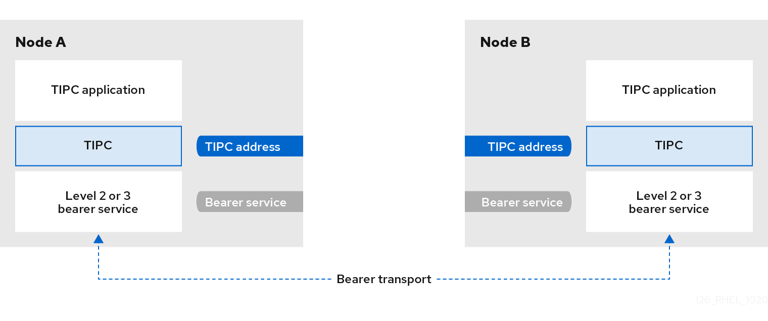
49.2. Loading the tipc module when the system boots
Before you can use the TIPC protocol, you must load the tipc kernel module. You can configure Red Hat Enterprise Linux to automatically load this kernel module automatically when the system boots.
Procedure
Create the
/etc/modules-load.d/tipc.conffile with the following content:tipc
Restart the
systemd-modules-loadservice to load the module without rebooting the system:# systemctl start systemd-modules-load
Verification
Use the following command to verify that RHEL loaded the
tipcmodule:# lsmod | grep tipc tipc 311296 0
If the command shows no entry for the
tipcmodule, RHEL failed to load it.
Additional resources
-
modules-load.d(5)man page on your system
49.3. Creating a TIPC network
To create a TIPC network, perform this procedure on each host that should join the TIPC network.
The commands configure the TIPC network only temporarily. To permanently configure TIPC on a node, use the commands of this procedure in a script, and configure RHEL to execute that script when the system boots.
Prerequisites
-
The
tipcmodule has been loaded. For details, see Loading the tipc module when the system boots
Procedure
Optional: Set a unique node identity, such as a UUID or the node’s host name:
# tipc node set identity host_nameThe identity can be any unique string consisting of a maximum 16 letters and numbers.
You cannot set or change an identity after this step.
Add a bearer. For example, to use Ethernet as media and
enp0s1device as physical bearer device, enter:# tipc bearer enable media eth device enp1s0- Optional: For redundancy and better performance, attach further bearers using the command from the previous step. You can configure up to three bearers, but not more than two on the same media.
- Repeat all previous steps on each node that should join the TIPC network.
Verification
Display the link status for cluster members:
# tipc link list broadcast-link: up 5254006b74be:enp1s0-525400df55d1:enp1s0: upThis output indicates that the link between bearer
enp1s0on node5254006b74beand bearerenp1s0on node525400df55d1isup.Display the TIPC publishing table:
# tipc nametable show Type Lower Upper Scope Port Node 0 1795222054 1795222054 cluster 0 5254006b74be 0 3741353223 3741353223 cluster 0 525400df55d1 1 1 1 node 2399405586 5254006b74be 2 3741353223 3741353223 node 0 5254006b74be-
The two entries with service type
0indicate that two nodes are members of this cluster. -
The entry with service type
1represents the built-in topology service tracking service. -
The entry with service type
2displays the link as seen from the issuing node. The range limit3741353223represents the peer endpoint’s address (a unique 32-bit hash value based on the node identity) in decimal format.
-
The two entries with service type
Additional resources
-
tipc-bearer(8)andtipc-namespace(8)man pages on your system
49.4. Additional resources
Red Hat recommends to use other bearer level protocols to encrypt the communication between nodes based on the transport media. For example:
- MACSec: See Using MACsec to encrypt layer 2 traffic
- IPsec: See Configuring a VPN with IPsec
-
For examples of how to use TIPC, clone the upstream GIT repository using the
git clone git://git.code.sf.net/p/tipc/tipcutilscommand. This repository contains the source code of demos and test programs that use TIPC features. Note that this repository is not provided by Red Hat. -
/usr/share/doc/kernel-doc-<kernel_version>/Documentation/output/networking/tipc.htmlprovided by thekernel-docpackage.
Chapter 50. Automatically configuring network interfaces in public clouds using nm-cloud-setup
Usually, a virtual machine (VM) has only one interface that is configurable by DHCP. However, DHCP cannot configure VMs with multiple network entities, such as interfaces, IP subnets, and IP addresses. Additionally, you cannot apply settings when the VM instance is running. To solve this runtime configuration issue, the nm-cloud-setup utility automatically retrieves configuration information from the metadata server of the cloud service provider and updates the network configuration of the host. The utility automatically picks up multiple network interfaces, multiple IP addresses, or IP subnets on one interface and helps to reconfigure the network of the running VM instance.
50.1. Configuring and pre-deploying nm-cloud-setup
To enable and configure network interfaces in public clouds, run nm-cloud-setup as a timer and service.
On Red Hat Enterprise Linux On Demand and AWS golden images, nm-cloud-setup is already enabled and no action is required.
Prerequisite
- A network connection exists.
The connection uses DHCP.
By default, NetworkManager creates a connection profile which uses DHCP. If no profile was created because you set the
no-auto-defaultparameter in/etc/NetworkManager/NetworkManager.conf, create this initial connection manually.
Procedure
Install the
nm-cloud-setuppackage:# dnf install NetworkManager-cloud-setupCreate and run the snap-in file for the
nm-cloud-setupservice:Use the following command to start editing the snap-in file:
# systemctl edit nm-cloud-setup.serviceIt is important to either start the service explicitly or reboot the system to make configuration settings effective.
Use the
systemdsnap-in file to configure the cloud provider innm-cloud-setup. For example, to use Amazon EC2, enter:[Service] Environment=NM_CLOUD_SETUP_EC2=yes
You can set the following environment variables to enable the cloud provide you use:
-
NM_CLOUD_SETUP_AZUREfor Microsoft Azure -
NM_CLOUD_SETUP_EC2for Amazon EC2 (AWS) -
NM_CLOUD_SETUP_GCPfor Google Cloud Platform(GCP) -
NM_CLOUD_SETUP_ALIYUNfor Alibaba Cloud (Aliyun)
-
- Save the file and quit the editor.
Reload the
systemdconfiguration:# systemctl daemon-reloadEnable and start the
nm-cloud-setupservice:# systemctl enable --now nm-cloud-setup.serviceEnable and start the
nm-cloud-setuptimer:# systemctl enable --now nm-cloud-setup.timer
Additional resources
-
nm-cloud-setup(8)man page on your system - Configuring an Ethernet connection
50.2. Understanding the role of IMDSv2 and nm-cloud-setup in the RHEL EC2 instance
The instance metadata service (IMDS) in Amazon EC2 allows you to manage permissions to access instance metadata of a running Red Hat Enterprise Linux (RHEL) EC2 instance. The RHEL EC2 instance uses IMDS version 2 (IMDSv2), a session-oriented method. By using the nm-cloud-setup utility, administrators can reconfigure the network and automatically update the configuration of running RHEL EC2 instances. The nm-cloud-setup utility handles IMDSv2 API calls by using IMDSv2 tokens without any user intervention.
-
IMDS runs on a link-local address
169.254.169.254for providing access to native applications on a RHEL EC2 instance. - After you have specified and configured IMDSv2 for each RHEL EC2 instance for applications and users, you can no longer access IMDSv1.
- By using IMDSv2, the RHEL EC2 instance maintains metadata without using the IAM role while remaining accessible through the IAM role.
-
When the RHEL EC2 instance boots, the
nm-cloud-setuputility automatically runs to fetch the EC2 instance API access token for using the RHEL EC2 instance API.
Use the IMDSv2 token as an HTTP header to check the details of the EC2 environment.
Additional resources
-
nm-cloud-setup(8)man page on your system