Using AMQ Interconnect
For Use with AMQ Interconnect 1.0
Abstract
Chapter 1. Overview
AMQ Interconnect is a lightweight AMQP message router for building scalable, available, and performant messaging networks.
AMQ Interconnect is based on Dispatch Router from the Apache Qpid™ project.
1.1. Key Features
- Connects clients and brokers into an internet-scale messaging network with uniform addressing
- Supports high-performance direct messaging
- Uses redundant network paths to route around failures
- Streamlines the management of large deployments
1.2. Supported Configurations
AMQ Interconnect is supported on Red Hat Enterprise Linux 6 and 7. See Red Hat JBoss AMQ 7 Supported Configurations for more information.
1.3. Theory of Operation
This section introduces some key concepts about AMQ Interconnect
1.3.1. Overview
AMQ Interconnect is an application layer program running as a normal user program or as a daemon.
The router accepts AMQP connections from clients and creates AMQP connections to brokers or AMQP-based services. The router classifies incoming AMQP messages and routes the messages between message producers and message consumers.
The router is meant to be deployed in topologies of multiple routers, preferably with redundant paths. It uses link-state routing protocols and algorithms similar to OSPF or IS-IS from the networking world to calculate the best path from every message source to every message destination and to recover quickly from failures. The router relies on redundant network paths to provide continued connectivity in the face of system or network failure.
A messaging client can make a single AMQP connection into a messaging bus built with routers and, over that connection, exchange messages with one or more message brokers connected to any router in the network. At the same time the client can exchange messages directly with other endpoints without involving a broker at all.
1.3.2. Connections
AMQ Interconnect connects clients, servers, AMQP services, and other routers through network connections.
1.3.2.1. Listener
The router provides listeners that accept client connections. A client connecting to a router listener uses the same methods that it would use to connect to a broker. From the client’s perspective the router connection and link establishment are identical to broker connection and link establishment.
Several types of listeners are defined by their role.
| Role | Description |
|---|---|
|
| The connection is used for AMQP clients using normal message delivery. |
|
| The connection is assumed to be to another router in the network. Inter-router discovery and routing protocols can only be used over inter-router connections. |
|
| The connection is a broker or other resource that holds known addresses. The router will use this connection to create links as necessary. The addresses are available for routing only after the remote resource has created a connection. |
1.3.2.2. Connector
The router can also be configured to create outbound connections to messaging brokers or other AMQP entities using connectors. A connector is defined with the network address of the broker and the name or names of the resources that are available in that broker. When a router connects to a broker through a connector it uses the same methods a normal messaging client would use when connecting to the broker.
Several types of connectors are defined by their role.
| Role | Description |
|---|---|
|
| The connection is used for AMQP clients using normal message delivery. On this connector the router will initiate the connection but it will never create any links. Links are to be created by the peer that accepts the connection. |
|
| The connection is assumed to be to another router in the network. Inter-router discovery and routing protocols can only be used over inter-router connections. |
|
| The connection is to a broker or other resource that holds known addresses. The router will use this connection to create links as necessary. The addresses are available for routing only after the router has created a connection to the remote resource. |
1.3.3. Addresses
AMQP addresses are used to control the flow of messages across a network of routers. Addresses are used in a number of different places in the AMQP 1.0 protocol. They can be used in a specific message in the to and reply-to fields of a message’s properties. They are also used during the creation of links in the address field of a source or a target.
Addresses in this discussion refer to AMQP protocol addresses and not to TCP/IP network addresses. TCP/IP network addresses are used by messaging clients, brokers, and routers to create AMQP connections. AMQP protocol addresses are the names of source and destination endpoints for messages within the messaging network.
Addresses designate various kinds of entities in a messaging network:
- Endpoint processes that consume data or offer a service
- Topics that match multiple consumers to multiple producers
Entities within a messaging broker:
- Queues
- Durable Topics
- Exchanges
The syntax of an AMQP address is opaque as far as the router network is concerned. A syntactical structure may be used by the administrator who creates addresses but the router treats them as opaque strings.
The router maintains several classes of address based on how the address is configured or discovered.
| Address Type | Description |
|---|---|
| Mobile | The address is a rendezvous point between senders and receivers. The router aggregates and serializes messages from senders and distributes messages to receivers. |
| Link route | The address defines a private messaging path between a sender and a receiver. The router simply passes messages between the end points. |
1.3.3.1. Mobile Addresses
Routers consider addresses to be mobile such that any users of an address may be directly connected to any router in a network and may move around the topology. In cases where messages are broadcast to or balanced across multiple consumers, the address users may be connected to multiple routers in the network.
Mobile addresses are rendezvous points for senders and receivers. Messages arrive at the mobile address and are dispatched to their destinations according to the routing defined for the mobile address. The details of these routing patterns are discussed later.
Mobile addresses may be discovered during normal router operation or configured through management settings.
1.3.3.1.1. Discovered Mobile Addresses
Mobile addresses are created when a client creates a link to a source or destination address that is unknown to the router network.
Suppose a service provider wants to offer my-service that clients may use. The service provider must open a receiver link with source address my-service. The router creates a mobile address my-service and propagates the address so that it is known to every router in the network.
Later a client wants to use the service and creates a sending link with target address my-service. The router matches the service provider’s receiver having source address my-service to the client’s sender having target address my-service and routes messages between the two.
Any number of other clients can create links to the service as well. The clients do not have to know where in the router network the service provider is physically located nor are the clients required to connect to a specific router to use the service. Regardless of how many clients are using the service the service provider needs only a single connection and link into the router network.
Another view of this same scenario is when a client tries to use the service before service provider has connected to the network. In this case the router network creates the mobile address my-service as before. However, since the mobile address has only client sender links and no receiver links the router stalls the clients and prevents them from sending any messages. Later, after the service provider connects and creates the receiver link, the router will issue credits to the clients and the messages will begin to flow between the clients and the service.
The service provider can connect, disconnect, and reconnect from a different location without having to change any of the clients or their connections. Imagine having the service running on a laptop. One day the connection is from corporate headquarters and the next day the connection is from some remote location. In this case the service provider’s computer will typically have different host IP addresses for each connection. Using the router network the service provider connects to the router network and offers the named service and the clients connect to the router network and consume from the named service. The router network routes messages between the mobile addresses effectively masking host IP addresses of the service provider and the client systems.
1.3.3.1.2. Configured Mobile Addresses
Mobile addresses may be configured using the router autoLink object. An address created via an autoLink represents a queue, topic, or other service in an external broker. Logically the autoLink addresses are treated by the router network as if the broker had connected to the router and offered the services itself.
For each configured mobile address the router will create a single link to the external resource. Messages flow between sender links and receiver links the same regardless if the mobile address was discovered or configured.
Multiple autoLink objects may define the same address on multiple brokers. In this case the router network creates a sharded resource split between the brokers. Any client can seamlessly send and receive messages from either broker.
Note that the brokers do not need to be clustered or federated to receive this treatment. The brokers may even be from different vendors or be different versions of the same broker yet still work together to provide a larger service platform.
1.3.3.2. Link Route Addresses
Link route addresses may be configured using the router linkRoute object. An link route address represents a queue, topic, or other service in an external broker similar to addresses configured by autoLink objects. For link route addresses the router propagates a separate link attachment to the broker resource for each incoming client link. The router does not automatically create any links to the broker resource.
Using link route addresses the router network does not participate in aggregated message distribution. The router simply passes message delivery and settlement between the two end points.
1.3.4. Message Routing
Addresses have semantics associated with them that are assigned when the address is provisioned or discovered. The semantics of an address control how routers behave when they see the address being used. Address semantics include the following considerations:
- Routing pattern - balanced, closest, multicast
- Routing mechanism - message routed, link routed
1.3.4.1. Routing Patterns
Routing patterns define the paths that a message with a mobile address can take across a network. These routing patterns can be used for both direct routing, in which the router distributes messages between clients without a broker, and indirect routing, in which the router enables clients to exchange messages through a broker.
| Pattern | Description |
|---|---|
| Balanced | An anycast method which allows multiple receivers to use the same address. In this case, messages (or links) are routed to exactly one of the receivers and the network attempts to balance the traffic load across the set of receivers using the same address. This routing delivers messages to receivers based on how quickly they settle the deliveries. Faster receivers get more messages. |
| Closest | An anycast method in which even if there are more receivers for the same address, every message is sent along the shortest path to reach the destination. This means that only one receiver will get the message. Each message is delivered to the closest receivers in terms of topology cost. If there are multiple receivers with the same lowest cost, deliveries will be spread evenly among those receivers. |
| Multicast | Having multiple consumers on the same address at the same time, messages are routed such that each consumer receives one copy of the message. |
1.3.4.2. Routing Mechanisms
The fact that addresses can be used in different ways suggests that message routing can be accomplished in different ways. Before going into the specifics of the different routing mechanisms, it would be good to first define what is meant by the term routing:
In a network built of multiple, interconnected routers 'routing'
determines which connection to use to send a message directly
to its destination or one step closer to its destination.
Each router serves as the terminus of a collection of incoming and outgoing links. Some of the links are designated for message routing, and others are designated for link routing. In both cases, the links either connect directly to endpoints that produce and consume messages, or they connect to other routers in the network along previously established connections.
1.3.4.2.1. Message Routed
Message routing occurs upon delivery of a message and is done based on the address in the message’s to field.
When a delivery arrives on an incoming message-routing link, the router extracts the address from the delivered message’s to field and looks the address up in its routing table. The lookup results in zero or more outgoing links onto which the message shall be resent.
Message routing can also occur without an address in the message’s to field if the incoming link has a target address. In fact, if the sender uses a link with a target address, the to field shall be ignored even if used.
1.3.4.2.2. Link Routed
Link routing occurs when a new link is attached to the router across one of its AMQP connections. It is done based on the target.address field of an inbound link and the source.address field of an outbound link.
Link routing uses the same routing table that message routing uses. The difference is that the routing occurs during the link-attach operation, and link attaches are propagated along the appropriate path to the destination. What results is a chain of links, connected end-to-end, from source to destination. It is similar to a virtual circuit in a telecom system.
Each router in the chain holds pairs of link termini that are tied together. The router then simply exchanges all deliveries, delivery state changes, and link state changes between the two termini.
The endpoints that use the link chain do not see any difference in behavior between a link chain and a single point-to-point link. All of the features available in the link protocol (flow control, transactional delivery, and so on) are available over a routed link-chain.
1.3.4.3. Message Settlement
Messages may be delivered with varying degrees of reliability.
- At most once
- At least once
- Exactly once
The reliability is negotiated between the client and server during link establishment. The router handles all levels of reliability by treating messages as either pre-settled or unsettled.
| Delivery | Handling |
|---|---|
| Pre-settled | If the arriving delivery is pre-settled (that is, fire and forget), the incoming delivery shall be settled by the router, and the outgoing deliveries shall also be pre-settled. In other words, the pre-settled nature of the message delivery is propagated across the network to the message’s destination. |
| Unsettled | Unsettled delivery is also propagated across the network. Because unsettled delivery records cannot be discarded, the router tracks the incoming deliveries and keeps the association of the incoming deliveries to the resulting outgoing deliveries. This kept association allows the router to continue to propagate changes in delivery state (settlement and disposition) back and forth along the path which the message traveled. |
1.3.5. Security
AMQ Interconnect uses the SSL/TLS protocol and related certificates and SASL protocol mechanisms to encrypt and authenticate remote peers. Router listeners act as network servers and router connectors act as network clients. Both connection types may be configured securely with SSL/TLS and SASL.
The router Policy module is an optional authorization mechanism enforcing user connection restrictions and AMQP resource access control.
1.4. Document Conventions
In this document, sudo is used for any command that requires root privileges. You should always exercise caution when using sudo, as any changes can affect the entire system.
For more information about using sudo, see The sudo Command.
Chapter 2. Installation
AMQ Interconnect 1.0 is distributed as a set of RPM packages, which are available through your Red Hat subscription.
Procedure
Ensure your subscription has been activated and your system is registered.
For more information about using the customer portal to activate your Red Hat subscription and register your system for packages, see Using Your Subscription.
Subscribe to the required repositories:
Red Hat Enterprise Linux 6
$ sudo subscription-manager repos --enable=amq-interconnect-1-for-rhel-6-server-rpms --enable=a-mq-clients-1-for-rhel-6-server-rpms
Red Hat Enterprise Linux 7
$ sudo subscription-manager repos --enable=amq-interconnect-1-for-rhel-7-server-rpms --enable=a-mq-clients-1-for-rhel-7-server-rpms
Use the
yumcommand to install theqpid-dispatch-routerandqpid-dispatch-toolspackages and their dependencies:$ sudo yum install qpid-dispatch-router qpid-dispatch-tools
Use the
whichcommand to verify that theqdrouterdexecutable is present.$ which qdrouterd /usr/sbin/qdrouterd
The
qdrouterdexecutable should be located at/usr/sbin/qdrouterd.
Chapter 3. Getting Started
Before configuring AMQ Interconnect, you should understand how to start the router, how it is configured by default, and how to use it in a simple peer-to-peer configuration.
3.1. Starting the Router
Procedure
To start the router with the default configuration, do one of the following:
To… Enter this command… Run the router as a service in Red Hat Enterprise Linux 6
$ sudo service qdrouterd start
Run the router as a service in Red Hat Enterprise Linux 7
$ systemctl start qdrouterd.service
Run the router as a daemon
$ qdrouterd -d
To start the router in the foreground, do not use the
-dparameter.NoteYou can specify a different configuration file with which to start the router. For more information, see Changing a Router’s Configuration.
The router starts, using the default configuration file stored at
/etc/qpid-dispatch/qdrouterd.conf.View the log to verify the router status:
$ qdstat --log
This example shows that the router was correctly installed, is running, and is ready to route traffic between clients:
$ qdstat --log
Fri May 20 09:38:03 2017 SERVER (info) Container Name: Router.A 1
Fri May 20 09:38:03 2017 ROUTER (info) Router started in Standalone mode 2
Fri May 20 09:38:03 2017 ROUTER_CORE (info) Router Core thread running. 0/Router.A
Fri May 20 09:38:03 2017 ROUTER_CORE (info) In-process subscription M/$management
Fri May 20 09:38:03 2017 AGENT (info) Activating management agent on $_management_internal 3
Fri May 20 09:38:03 2017 ROUTER_CORE (info) In-process subscription L/$management
Fri May 20 09:38:03 2017 ROUTER_CORE (info) In-process subscription L/$_management_internal
Fri May 20 09:38:03 2017 DISPLAYNAME (info) Activating DisplayNameService on $displayname
Fri May 20 09:38:03 2017 ROUTER_CORE (info) In-process subscription L/$displayname
Fri May 20 09:38:03 2017 CONN_MGR (info) Configured Listener: 0.0.0.0:amqp proto=any role=normal 4
Fri May 20 09:38:03 2017 POLICY (info) Policy configured maximumConnections: 0, policyFolder: '', access rules enabled: 'false'
Fri May 20 09:38:03 2017 POLICY (info) Policy fallback defaultApplication is disabled
Fri May 20 09:38:03 2017 SERVER (info) Operational, 4 Threads Running 5
- 1
- The name of this router instance.
- 2
- By default, the router starts in standalone mode, which means that it cannot connect to other routers or be used in a router network.
- 3
- The management agent. It provides the
$managementaddress, through which management tools such asqdmanageandqdstatcan perform create, read, update, and delete (CRUD) operations on the router. As an AMQP endpoint, the management agent supports all operations defined by the AMQP management specification (Draft 9). - 4
- A listener is started on all available network interfaces and listens for connections on the standard AMQP port (5672, which is not encrypted).
- 5
- Threads for handling message traffic and all other internal operations.
3.2. Routing Messages in a Peer-to-Peer Configuration
This example demonstrates how the router can connect clients by receiving and sending messages between them. It uses the router’s default configuration file and does not require a broker.
Figure 3.1. Peer-to-peer Communication

As the diagram indicates, the configuration consists of an AMQ Interconnect component with two clients connected to it: a sender and a receiver. The receiver wants to receive messages on a specific address, and the sender sends messages to that address.
A broker is not used in this example, so there is no "store and forward" mechanism in the middle. Instead, the messages flow from sender to receiver only if the receiver is online, and the sender can confirm that the messages have arrived at their destination.
This example uses the AMQ Python client to start a receiver client, and then send five messages from the sender client.
Prerequisites
The AMQ Python client must be installed before you can complete the peer-to-peer routing example. For more information, see Installation in Using the AMQ Python Client.
Procedure
3.2.1. Starting the Receiver Client
In this example, the receiver client is started first. This means that the messages will be sent as soon as the sender client is started.
In practice, the order in which you start senders and receivers does not matter. In both cases, messages will be sent as soon as the receiver comes online.
Procedure
To start the receiver by using the Python receiver client, navigate to the Python examples directory and run the
simple_recv.pyexample:$ cd INSTALL_DIR/examples/python/ $ python simple_recv.py -a 127.0.0.1:5672/examples -m 5This command starts the receiver and listens on the default address (
127.0.0.1:5672/examples). The receiver is also set to receive a maximum of five messages.
3.2.2. Sending Messages
After starting the receiver client, you can send messages from the sender. These messages will travel through the router to the receiver.
Procedure
In a new terminal window, navigate to the Python examples directory and run the
simple_send.pyexample:$ cd INSTALL_DIR/examples/python/ $ python simple_send.py -a 127.0.0.1:5672/examples -m 5This command sends five auto-generated messages to the default address (
127.0.0.1:5672/examples) and then confirms that they were delivered and acknowledged by the receiver:all messages confirmed
The receiver client receives the messages and displays their content:
{u'sequence': 1L}
{u'sequence': 2L}
{u'sequence': 3L}
{u'sequence': 4L}
{u'sequence': 5L}
Chapter 4. Configuration
Before starting AMQ Interconnect, you should understand where the router’s configuration file is stored, how the file is structured, and the methods you can use to modify it.
4.1. Accessing the Router Configuration File
The router’s configuration is defined in the router configuration file. You can access this file to view and modify that configuration.
Procedure
Open the following file:
/etc/qpid-dispatch/qdrouterd.conf.When AMQ Interconnect is installed,
qdrouterd.confis installed in this directory by default. When the router is started, it runs with the settings defined in this file.For more information about the router configuration file (including available entities and attributes), see the qdrouterd man page.
4.2. How the Router Configuration File is Structured
Before you can make changes to a router configuration file, you should understand how the file is structured.
The configuration file contains sections. A section is a configurable entity, and it contains a set of attribute name-value pairs that define the settings for that entity. The syntax is as follows:
sectionName {
    attributeName: attributeValue
    attributeName: attributeValue
    ...
}
4.3. Changing a Router’s Configuration
You can use different methods for changing a router’s configuration based on whether the router is currently running, and whether you want the change to take effect immediately.
Choices
4.3.1. Making a Permanent Change to the Router’s Configuration
You can make a permanent change to the router’s configuration by editing the router’s configuration file directly. You must restart the router for the changes to take effect, but the changes will be saved even if the router is stopped.
Procedure
Do one of the following:
-
Edit the default configuration file (
/etc/qpid-dispatch/qdrouterd.conf). - Create a new configuration file.
-
Edit the default configuration file (
Start (or restart) the router.
If you created a new configuration file, you must specify the path using the
--confparameter. For example, the following command starts the router with a non-default configuration file:# qdrouterd -d --conf /etc/qpid-dispatch/new-configuration-file.conf
4.3.2. Changing the Configuration for a Running Router
If the router is running, you can change its configuration on the fly. The changes you make take effect immediately, but are lost if the router is stopped.
Procedure
Use
qdmanageto change the configuration.For more information about using
qdmanage, see Managing AMQ Interconnect Using qdmanage.
4.4. Default Configuration Settings
The router’s configuration file controls the way in which the router functions. The default configuration file contains the minimum number of settings required for the router to run. As you become more familiar with the router, you can add to or change these settings, or create your own configuration files.
When you installed AMQ Interconnect, the default configuration file was added at the following path: /etc/qpid-dispatch/qdrouterd.conf. It includes some basic configuration settings that define the router’s operating mode, how it listens for incoming connections, and routing patterns for the message routing mechanism.
Default Configuration File
router {
    mode: standalone 1
    id: Router.A 2
}

listener { 3
    host: 0.0.0.0 4
    port: amqp 5
    authenticatePeer: no 6
}

address { 7
    prefix: closest
    distribution: closest
}

address {
    prefix: multicast
    distribution: multicast
}

address {
    prefix: unicast
    distribution: closest
}

address {
    prefix: exclusive
    distribution: closest
}

address {
    prefix: broadcast
    distribution: multicast
}
- 1
- By default, the router operates in standalone mode. This means that it can only communicate with endpoints that are directly connected to it. It cannot connect to other routers, or participate in a router network.
- 2
- The unique identifier of the router. This ID is used as the
container-id(container name) at the AMQP protocol level. It is required, and the router will not start if this attribute is not defined. - 3
- The
listenerentity handles incoming connections from client endpoints. - 4
- The IP address on which the router will listen for incoming connections. By default, the router is configured to listen on all network interfaces.
- 5
- The port on which the router will listen for incoming connections. By default, the default AMQP port (5672) is specified with a symbolic service name.
- 6
- Specifies whether the router should authenticate peers before they can connect to the router. By default, peer authentication is not required.
- 7
- By default, the router is configured to use the message routing mechanism. Each
addressentity defines how messages that are received with a particular addressprefixshould be distributed. For example, all messages with addresses that start withclosestwill be distributed using theclosestdistribution pattern.
If a client requests a message with an address that is not defined in the router’s configuration file, the balanced distribution pattern will be used automatically.
4.5. Setting Essential Configuration Properties
The router’s default configuration settings enable the router to run with minimal configuration. However, you may need to change some of these settings for the router to run properly in your environment.
Procedure
Open the router’s configuration file.
If you are changing the router’s default configuration file, the file is located at
/etc/qpid-dispatch/qdrouterd.conf.To define essential router information, change the following attributes as needed in the
routersection:router { mode: STANDALONE/INTERIOR id: ROUTER_ID }modeSpecify one of the following modes:
-
standalone- Use this mode if the router does not communicate with other routers and is not part of a router network. When operating in this mode, the router only routes messages between directly connected endpoints. -
interior- Use this mode if the router is part of a router network and needs to collaborate with other routers.
-
id- The unique identifier for the router. This ID will also be the container name at the AMQP protocol level.
For information about additional attributes, see Router in the Configuration Reference.
If necessary for your environment, secure the router.
Connect the router to other routers, clients, and brokers.
Set up routing for your environment:
- Set up logging.
Chapter 5. Network Connections
Connections define how the router communicates with clients, other routers, and brokers. You can configure incoming connections to define how the router listens for data from clients and other routers, and you can configure outgoing connections to define how the router sends data to other routers and brokers.
5.1. Listening for Incoming Connections
Listening for incoming connections involves setting the host and port on which the router should listen for traffic.
Procedure
In the router’s configuration file, add a
listener:listener { host: HOST_NAME/ADDRESS port: PORT_NUMBER/NAME ... }host- Either an IP address (IPv4 or IPv6) or hostname on which the router should listen for incoming connections.
port- The port number or symbolic service name on which the router should listen for incoming connections.
For information about additional attributes, see Listener in the Configuration Reference.
If necessary, secure the connection.
If you have set up SSL/TLS or SASL in your environment, you can configure the router to only accept encrypted or authenticated communication on this connection.
-
If you want the router to listen for incoming connections on additional hosts or ports, configure an additional
listenerentity for each host and port.
5.2. Adding Outgoing Connections
Configuring outgoing connections involves setting the host and port on which the router should connect to other routers and brokers.
Procedure
In the router’s configuration file, add a
connector:connector { name: NAME host: HOST_NAME/ADDRESS port: PORT_NUMBER/NAME ... }name-
The name of the
connector. You should specify a name that describes the entity to which the connector connects. This name is used by configured addresses (for example, alinkRouteentity) in order to specify which connection should be used for them. host- Either an IP address (IPv4 or IPv6) or hostname on which the router should connect.
port- The port number or symbolic service name on which the router should connect.
For information about additional attributes, see Connector in the Configuration Reference.
If necessary, secure the connection.
If you have set up SSL/TLS or SASL in your environment, you can configure the router to only send encrypted or authenticated communication on this connection.
-
For each remaining router or broker to which this router should connect, configure an additional
connectorentity.
Chapter 6. Security
You can configure AMQ Interconnect to communicate with clients, routers, and brokers in a secure way by authenticating and encrypting the router’s connections. AMQ Interconnect supports the following security protocols:
- SSL/TLS for certificate-based encryption and mutual authentication
- SASL for authentication and payload encryption
6.1. Setting Up SSL/TLS for Encryption and Authentication
Before you can secure incoming and outgoing connections using SSL/TLS encryption and authentication, you must first set up the SSL/TLS profile in the router’s configuration file.
Prerequisites
You must have the following files in PEM format:
- An X.509 CA certificate (used for signing the router certificate for the SSL/TLS server authentication feature).
- A private key (with or without password protection) for the router.
- An X.509 router certificate signed by the X.509 CA certificate.
Procedure
In the router’s configuration file, add an
sslProfilesection:sslProfile { name: NAME certDb: PATH.pem certFile: PATH.pem keyFile: PATH.pem password: PASSWORD/PATH_TO_PASSWORD_FILE ... }nameA name for the SSL/TLS profile. You can use this name to refer to the profile from the incoming and outgoing connections.
For example:
name: router-ssl-profile
certDbThe absolute path to the database that contains the public certificates of trusted certificate authorities (CA).
For example:
certDb: /qdrouterd/ssl_certs/ca-cert.pem
certFileThe absolute path to the file containing the PEM-formatted public certificate to be used on the local end of any connections using this profile.
For example:
certFile: /qdrouterd/ssl_certs/router-cert-pwd.pem
keyFileThe absolute path to the file containing the PEM-formatted private key for the above certificate.
For example:
keyFile: /qdrouterd/ssl_certs/router-key-pwd.pem
passwordFileorpasswordIf the private key is password-protected, you must provide the password by either specifying the absolute path to a file containing the password that unlocks the certificate key, or entering the password directly in the configuration file.
For example:
password: routerKeyPassword
For information about additional
sslProfileattributes, see sslProfile in the Configuration Reference.
6.2. Setting Up SASL for Authentication and Payload Encryption
If you plan to use SASL to authenticate connections, you must first add the SASL attributes to the router entity in the router’s configuration file. These attributes define a set of SASL parameters that can be used by the router’s incoming and outgoing connections.
Prerequisites
Before you can set up SASL, you must have the following:
Procedure
In the router’s configuration file, add the following attributes to the
routersection:router { ... saslConfigPath: PATH saslConfigName: FILE_NAME }saslConfigPathThe absolute path to the SASL configuration file.
For example:
saslConfigPath: /qdrouterd/security
saslConfigNameThe name of the SASL configuration file. This name should not include the
.conffile extension.For example:
saslConfigName: qdrouterd_sasl
6.3. Securing Incoming Connections
You can secure incoming connections by configuring each connection’s listener entity for encryption, authentication, or both.
Prerequisites
Before securing incoming connections, the security protocols you plan to use should be set up.
Choices
6.3.1. Adding SSL/TLS Encryption to an Incoming Connection
You can configure an incoming connection to accept encrypted connections only. By adding SSL/TLS encryption, to connect to this router, a remote peer must first start an SSL/TLS handshake with the router and be able to validate the server certificate received by the router during the handshake.
Procedure
In the router’s configuration file, add the following attributes to the connection’s
listenerentity:listener { ... sslProfile: SSL_PROFILE_NAME requireSsl: yes }sslProfile- The name of the SSL/TLS profile you set up.
requireSsl-
Enter
yesto require all clients connecting to the router on this connection to use encryption.
6.3.2. Adding SASL Authentication to an Incoming Connection
You can configure an incoming connection to authenticate the client using SASL. You can use SASL authentication with or without SSL/TLS encryption.
Procedure
In the router’s configuration file, add the following attributes to the connection’s
listenersection:listener { ... authenticatePeer: yes saslMechanisms: MECHANISMS }authenticatePeer-
Set this attribute to
yesto require the router to authenticate the identity of a remote peer before it can use this incoming connection. saslMechanismsThe SASL authentication mechanism (or mechanisms) to use for peer authentication. You can choose any of the Cyrus SASL authentication mechanisms except for
ANONYMOUS. To specify multiple authentication mechanisms, separate each mechanism with a space.For a full list of supported Cyrus SASL authentication mechanisms, see Authentication Mechanisms.
6.3.3. Adding SSL/TLS Client Authentication to an Incoming Connection
You can configure an incoming connection to authenticate the client using SSL/TLS.
The base SSL/TLS configuration provides content encryption and server authentication, which means that remote peers can verify the router’s identity, but the router cannot verify a peer’s identity.
However, you can require an incoming connection to use SSL/TLS client authentication, which means that remote peers must provide an additional certificate to the router during the SSL/TLS handshake. By using this certificate, the router can verify the client’s identity without using a username and password.
You can use SSL/TLS client authentication with or without SASL authentication.
Procedure
In the router’s configuration, file, add the following attribute to the connection’s
listenerentity:listener { ... authenticatePeer: yes }authenticatePeer-
Set this attribute to
yesto require the router to authenticate the identity of a remote peer before it can use this incoming connection.
6.3.4. Adding SASL Payload Encryption to an Incoming Connection
If you do not use SSL/TLS, you can still encrypt the incoming connection by using SASL payload encryption.
Procedure
In the router’s configuration file, add the following attributes to the connection’s
listenersection:listener { ... requireEncryption: yes saslMechanisms: MECHANISMS }requireEncryption-
Set this attribute to
yesto require the router to use SASL payload encryption for the connection. saslMechanismsThe SASL mechanism to use. You can choose any of the Cyrus SASL authentication mechanisms. To specify multiple authentication mechanisms, separate each mechanism with a space.
For a full list of supported Cyrus SASL authentication mechanisms, see Authentication Mechanisms.
6.4. Securing Outgoing Connections
You can secure outgoing connections by configuring each connection’s connector entity for encryption, authentication, or both.
Prerequisites
Before securing outgoing connections, the security protocols you plan to use should be set up.
6.4.1. Adding SSL/TLS Client Authentication to an Outgoing Connection
If an outgoing connection connects to an external client configured with mutual authentication, you should ensure that the outgoing connection is configured to provide the external client with a valid security certificate during the SSL/TLS handshake.
You can use SSL/TLS client authentication with or without SASL authentication.
Procedure
In the router’s configuration file, add the
sslProfileattribute to the connection’sconnectorentity:connector { ... sslProfile: SSL_PROFILE_NAME }sslProfile- The name of the SSL/TLS profile you set up.
6.4.2. Adding SASL Authentication to an Outgoing Connection
You can configure an outgoing connection to provide authentication credentials to the external container. You can use SASL authentication with or without SSL/TLS encryption.
Procedure
In the router’s configuration file, add the
saslMechanismsattribute to the connection’sconnectorentity:connector { ... saslMechanisms: MECHANISMS saslUsername: USERNAME saslPassword: PASSWORD }saslMechanismsOne or more SASL mechanisms to use to authenticate the router to the external container. You can choose any of the Cyrus SASL authentication mechanisms. To specify multiple authentication mechanisms, separate each mechanism with a space.
For a full list of supported Cyrus SASL authentication mechanisms, see Authentication Mechanisms.
saslUsername- If any of the SASL mechanisms uses username/password authentication, then provide the username to connect to the external container.
saslPassword- If any of the SASL mechanisms uses username/password authentication, then provide the password to connect to the external container.
Chapter 7. Routing
Routing is the process by which messages are delivered to their destinations. To accomplish this, AMQ Interconnect provides two routing mechanisms: message routing and link routing.
- Message routing
Routing is performed on messages as producers send them to a router. When a message arrives on a router, the router routes the message and its settlement based on the message’s address and routing pattern.
Figure 7.1. Message Routing

In this diagram, the message producer attaches a link to the router, and then sends a message over the link. When the router receives the message, it identifies the message’s destination based on the message’s address, and then uses its routing table to determine the best route to deliver the message either to its destination or to the next hop in the route. All dispositions (including settlement) are propagated along the same path that the original message transfer took. Flow control is handled between the sender and the router, and then between the router and the receiver.
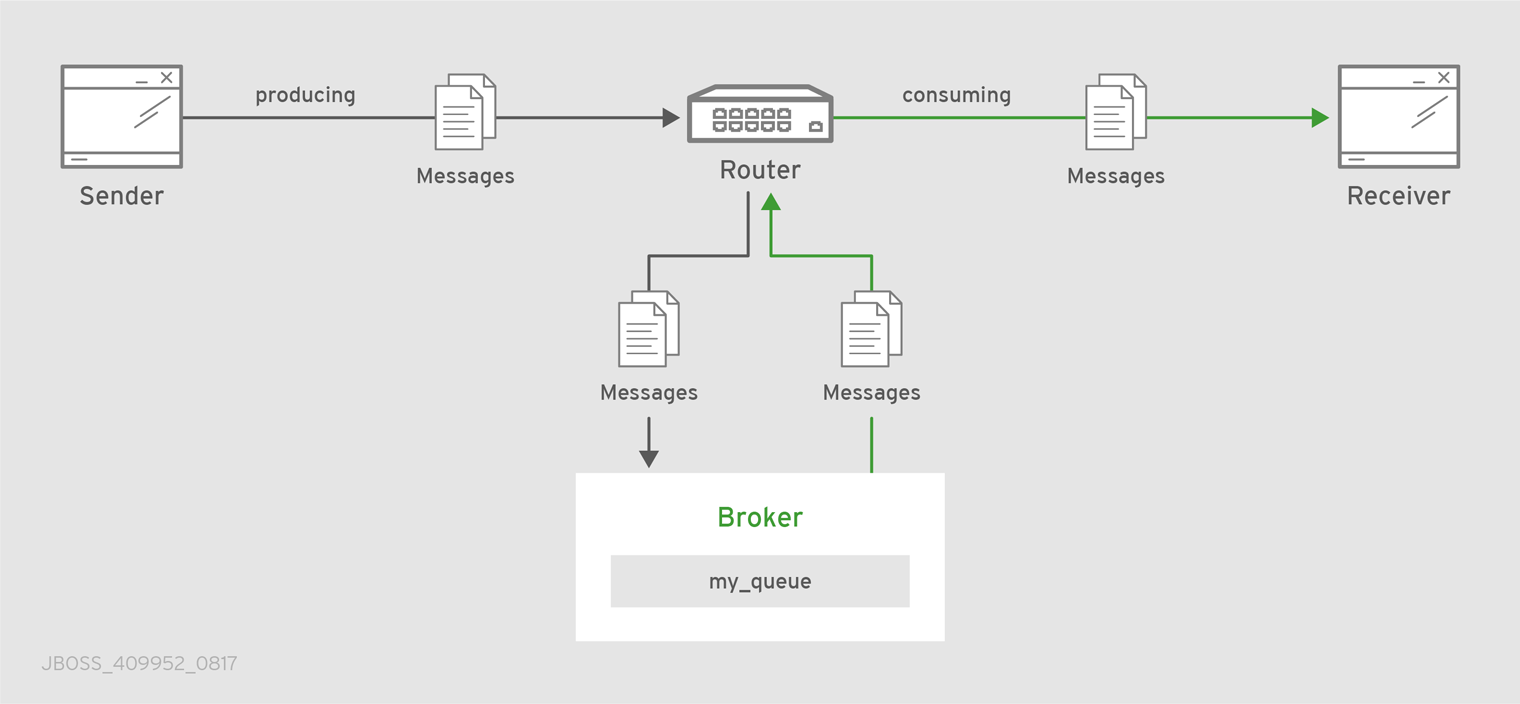
- Link routing
Routing is performed on link-attach frames, which are chained together to form a virtual messaging path that directly connects a sender and receiver. Once a link route is established, the transfer of message deliveries, flow frames, and dispositions is performed across the link route.
Figure 7.2. Link Routing

In this diagram, a router is connected to clients and to a broker, and it provides a link route to a queue on the broker (my_queue). The sender connects to the router, and the router propagates the link-attaches to the broker to form a direct link between the sender and the broker. The sender can begin sending messages to the queue, and the router passes the deliveries along the link route directly to the broker queue.
7.1. Comparison of Message Routing and Link Routing
While you can use either message routing or link routing to deliver messages to a destination, they differ in several important ways. Understanding these differences will enable you to choose the proper routing approach for any particular use case.
7.1.1. When to Use Message Routing
Message routing is the default routing mechanism. You can use it to route messages on a per-message basis between clients directly (direct-routed messaging), or to and from broker queues (brokered messaging).
Message routing is best suited to the following requirements:
Default, basic message routing.
AMQ Interconnect automatically routes messages by default, so manual configuration is only required if you want routing behavior that is different than the default.
Message-based routing patterns.
Message routing supports both anycast and multicast routing patterns. You can load-balance individual messages across multiple consumers, and multicast (or fan-out) messages to multiple subscribers.
Sharding messages across multiple broker instances when message delivery order is not important.
Sharding messages from one producer might cause that producer’s messages to be received in a different order than the order in which they were sent.
Message routing is not suitable for any of the following requirements:
Dedicated path through the router network.
For inter-router transfers, all message deliveries are placed on the same inter-router link. This means that the traffic for one address might affect the delivery of the traffic for another address.
Granular, end-to-end flow control.
With message routing, end-to-end flow control is based on the settlement of deliveries and therefore might not be optimal in every case.
- Transaction support.
- Server-side selectors.
7.1.2. When to Use Link Routing
Link routing requires more detailed configuration than message routing as well as an AMQP container that can accept incoming link-attaches (typically a broker). However, link routing enables you to satisfy more advanced use cases than message routing.
You can use link routing if you need to meet any of the following requirements:
Dedicated path through the router network.
With link routing, each link route has dedicated inter-router links through the network. Each link has its own dedicated message buffers, which means that the address will not have "head-of-line" blocking issues with other addresses.
Sharding messages across multiple broker instances with guaranteed delivery order.
Link routing to a sharded queue preserves the delivery order of the producer’s messages by causing all messages on that link to go to the same broker instance.
End-to-end flow control.
Flow control is "real" in that credits flow across the link route from the receiver to the sender.
Transaction support.
Link routing supports local transactions to a broker.
Server-side selectors.
With a link route, consumers can provide server-side selectors for broker subscriptions.
7.2. Configuring Message Routing
With message routing, routing is performed on messages as producers send them to a router. When a message arrives on a router, the router routes the message and its settlement based on the message’s address and routing pattern.
With message routing, you can do the following:
Route messages between clients (direct-routed, or brokerless messaging)
This involves configuring an address with a routing pattern. All messages sent to the address will be routed based on the routing pattern.
Route messages through a broker queue (brokered messaging)
This involves configuring a waypoint address to identify the broker queue and then connecting the router to the broker. All messages sent to the waypoint address will be routed to the broker queue.
7.2.1. Addresses
Addresses determine how messages flow through your router network. An address designates an endpoint in your messaging network, such as:
- Endpoint processes that consume data or offer a service
- Topics that match multiple consumers to multiple producers
Entities within a messaging broker:
- Queues
- Durable Topics
- Exchanges
When a router receives a message, it uses the message’s address to determine where to send the message (either its destination or one step closer to its destination).
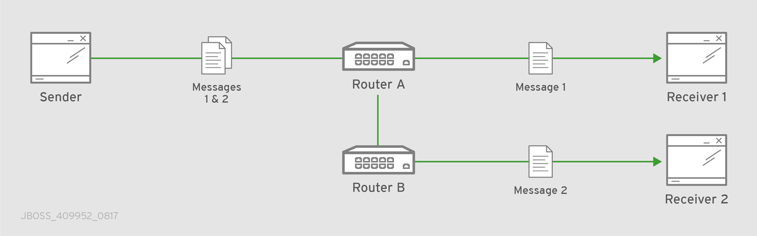
7.2.2. Routing Patterns
Each address has one of the following routing patterns, which define the path that a message with the address can take across the messaging network:
- Balanced
An anycast method that allows multiple consumers to use the same address. Each message is delivered to a single consumer only, and AMQ Interconnect attempts to balance the traffic load across the router network.
If multiple consumers are attached to the same address, each router determines which outbound path should receive a message by considering each path’s current number of unsettled deliveries. This means that more messages will be delivered along paths where deliveries are settled at higher rates.
NoteAMQ Interconnect neither measures nor uses message settlement time to determine which outbound path to use.
In this scenario, the messages are spread across both receivers regardless of path length:
Figure 7.3. Balanced Message Routing
- Closest
An anycast method in which every message is sent along the shortest path to reach the destination, even if there are other consumers for the same address.
AMQ Interconnect determines the shortest path based on the topology cost to reach each of the consumers. If there are multiple consumers with the same lowest cost, messages will be spread evenly among those consumers.
In this scenario, all messages sent by
Senderwill be delivered toReceiver 1:Figure 7.4. Closest Message Routing

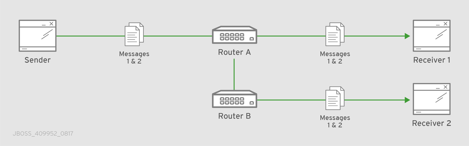
- Multicast
Messages are sent to all consumers attached to the address. Each consumer will receive one copy of the message.
In this scenario, all messages are sent to all receivers:
Figure 7.5. Multicast Message Routing
7.2.3. Message Settlement
Message settlement is negotiated between the producer and the router when the producer establishes a link to the router. Depending on the settlement pattern, messages might be delivered with any of the following degrees of reliability:
- At most once
- At least once
- Exactly once
AMQ Interconnect treats all messages as either pre-settled or unsettled, and it is responsible for propagating the settlement of each message it routes.
- Pre-settled
- Sometimes called fire and forget, the router settles the incoming and outgoing deliveries and propagates the settlement to the message’s destination. However, it does not guarantee delivery.
- Unsettled
The router propagates the settlement between the sender and receiver, and guarantees one of the following outcomes:
- The message is delivered and settled, with the consumer’s disposition indicated.
The delivery is settled with a disposition of
RELEASED.This means that the message did not reach its destination.
The delivery is settled with a disposition of
MODIFIED.This means that the message might or might not have reached its destination. The delivery is considered to be "in-doubt" and should be re-sent if "at least once" delivery is required.
- The link, session, or connection to AMQ Interconnect was dropped, and all deliveries are "in-doubt".
7.2.4. Routing Messages Between Clients
You can route messages between clients without using a broker. In a brokerless scenario (sometimes called direct-routed messaging), AMQ Interconnect routes messages between clients directly.
To route messages between clients, you configure an address with a routing distribution pattern. When a router receives a message with this address, the message is routed to its destination or destinations based on the address’s routing distribution pattern.
Procedure
In the router’s configuration file, add an
addresssection:address { prefix: ADDRESS_PREFIX distribution: balanced|closest|multicast ... }prefixThe address prefix. All messages that match this prefix will be distributed according to the distribution pattern you specify.
The prefix can match either an exact address or a segment within an address that is delimited by either a
.or/character. For example, the prefixmy_addresswould match the addressmy_addressas well asmy_address.1andmy_address/1. However, it would not matchmy_address1.distributionThe message distribution pattern. The default is
balanced, but you can specify any of the following options:-
balanced- Messages sent to the address will be routed to one of the receivers, and the routing network will attempt to balance the traffic load based on the rate of settlement. -
closest- Messages sent to the address are sent on the shortest path to reach the destination. It means that if there are multiple receivers for the same address, only the closest one will receive the message. multicast- Messages are sent to all receivers that are attached to the address in a publish/subscribe model.For more information about message distribution patterns, see Routing Patterns.
-
For information about additional attributes, see Address in the Configuration Reference.
Add the same
addresssection to any other routers that need to use the address.The
addressthat you added to this router configuration file only controls how this router distributes messages sent to the address. If you have additional routers in your router network that should distribute messages for this address, then you must add the sameaddresssection to each of their configuration files.
7.2.5. Routing Messages Through a Broker Queue
You can route messages to and from a broker queue to provide clients with access to the queue through a router. In this scenario, clients connect to a router to send and receive messages, and the router routes the messages to or from the broker queue.
You can route messages to a queue hosted on a single broker, or route messages to a sharded queue distributed across multiple brokers.
Figure 7.6. Brokered Messaging
In this diagram, the sender connects to the router and sends messages to my_queue. The router attaches an outgoing link to the broker, and then sends the messages to my_queue. Later, the receiver connects to the router and requests messages from my_queue. The router attaches an incoming link to the broker to receive the messages from my_queue, and then delivers them to the receiver.
You can also route messages to a sharded queue, which is a single, logical queue comprised of multiple, underlying physical queues. Using queue sharding, it is possible to distribute a single queue over multiple brokers. Clients can connect to any of the brokers that hold a shard to send and receive messages.
Figure 7.7. Brokered Messaging with Sharded Queue

In this diagram, a sharded queue (my_queue) is distributed across two brokers. The router is connected to the clients and to both brokers. The sender connects to the router and sends messages to my_queue. The router attaches an outgoing link to each broker, and then sends messages to each shard (by default, the routing distribution is balanced). Later, the receiver connects to the router and requests all of the messages from my_queue. The router attaches an incoming link to one of the brokers to receive the messages from my_queue, and then delivers them to the receiver.
Procedure
This address identifies the queue to which you want to route messages.
Add autolinks to connect the router to the broker.
Autolinks connect the router to the broker queue identified by the waypoint address.
- If the queue is sharded, add autolinks for each additional broker that hosts a shard.
7.2.5.1. Configuring Waypoint Addresses
A waypoint address identifies a queue on a broker to which you want to route messages. You need to configure the waypoint address on each router that needs to use the address. For example, if a client is connected to Router A to send messages to the broker queue, and another client is connected to Router B to receive those messages, then you would need to configure the waypoint address on both Router A and Router B.
Prerequisites
An incoming connection (listener) to which the clients can connect should be configured. This connection defines how the producers and consumers connect to the router to send and receive messages. For more information, see Adding Incoming Connections.
Procedure
Create waypoint addresses on each router that needs to use the address:
address { prefix: ADDRESS_PREFIX waypoint: yes }prefixThe address prefix that matches the broker queue to which you want to route messages.
The prefix can match either an exact address or a segment within an address that is delimited by either a
.or/character. For example, the prefixmy_addresswould match the addressmy_addressas well asmy_address.1andmy_address/1. However, it would not matchmy_address1.waypoint-
Set this attribute to
yesso that the router handles messages sent to this address as a waypoint.
7.2.5.2. Connecting a Router to the Broker
After you add waypoint addresses to identify the broker queue, you must connect a router to the broker using autolinks.
With autolinks, client traffic is handled on the router, not the broker. Clients attach their links to the router, and then the router uses internal autolinks to connect to the queue on the broker. Therefore, the queue will always have a single producer and a single consumer regardless of how many clients are attached to the router.
- If this router is different than the router that is connected to the clients, then add the waypoint address.
Add an outgoing connection to the broker:
connector { name: NAME host: HOST_NAME/ADDRESS port: PORT_NUMBER/NAME role: route-container ... }name-
The name of the
connector. Specify a name that describes the broker. host- Either an IP address (IPv4 or IPv6) or hostname on which the router should connect to the broker.
port- The port number or symbolic service name on which the router should connect to the broker.
role-
Specify
route-containerto indicate that this connection is for an external container (broker).
For information about additional attributes, see Connector in the Configuration Reference.
If you want to send messages to the broker queue, create an outgoing autolink to the broker queue:
autoLink { addr: ADDRESS connection: CONNECTOR_NAME dir: out ... }addr- The address of the broker queue. When the autolink is created, it will be attached to this address.
connection|containerID-
How the router should connect to the broker. You can specify either an outgoing connection (
connection) or the container ID of the broker (containerID). dir-
Set this attribute to
outto specify that this autolink can send messages from the router to the broker.
For information about additional attributes, see autoLink in the Configuration Reference.
If you want to receive messages from the broker queue, create an incoming autolink from the broker queue:
autoLink { addr: ADDRESS connection: CONNECTOR_NAME dir: in ... }addr- The address of the broker queue. When the autolink is created, it will be attached to this address.
connection|containerID-
How the router should connect to the broker. You can specify either an outgoing connection (
connection) or the container ID of the broker (containerID). dir-
Set this attribute to
into specify that this autolink can receive messages from the broker to the router.
For information about additional attributes, see autoLink in the Configuration Reference.
7.3. Configuring Link Routing
Link routing provides an alternative strategy for brokered messaging. A link route represents a private messaging path between a sender and a receiver in which the router passes the messages between end points. You can think of a link route as a "virtual connection" or "tunnel" that travels from a sender, through the router network, to a receiver.
With link routing, routing is performed on link-attach frames, which are chained together to form a virtual messaging path that directly connects a sender and receiver. Once a link route is established, the transfer of message deliveries, flow frames, and dispositions is performed across the link route.
7.3.1. Link Route Addresses
A link route address represents a broker queue, topic, or other service. When a client attaches a link route address to a router, the router propagates a link attachment to the broker resource identified by the address.
7.3.2. Link Route Routing Patterns
Routing patterns are not used with link routing, because there is a direct link between the sender and receiver. The router only makes a routing decision when it receives the initial link-attach request frame. Once the link is established, the router passes the messages along the link in a balanced distribution.
7.3.3. Link Route Flow Control
Unlike message routing, with link routing, the sender and receiver handle flow control directly: the receiver grants link credits, which is the number of messages it is able to receive. The router sends them directly to the sender, and then the sender sends the messages based on the credits that the receiver granted.
7.3.4. Creating a Link Route
Link routes establish a link between a sender and a receiver that travels through a router. You can configure inward and outward link routes to enable the router to receive link-attaches from clients and to send them to a particular destination.
With link routing, client traffic is handled on the broker, not the router. Clients have a direct link through the router to a broker’s queue. Therefore, each client is a separate producer or consumer.
Procedure
In the router configuration file, add an outgoing connection to the broker:
connector { name: NAME host: HOST_NAME/ADDRESS port: PORT_NUMBER/NAME role: route-container ... }name-
The name of the
connector. You should specify a name that describes the broker. host- Either an IP address (IPv4 or IPv6) or hostname on which the router should connect to the broker.
port- The port number or symbolic service name on which the router should connect to the broker.
role-
Specify
route-containerto indicate that this connection is for an external container (broker).
For information about additional attributes, see Connector in the Configuration Reference.
If you want clients to send messages on this link route, create an incoming link route:
linkRoute { prefix: ADDRESS_PREFIX connection: CONNECTOR_NAME dir: in ... }prefixThe address prefix that matches the broker queue to which you want to send messages. All messages that match this prefix will be distributed along the link route.
The prefix can match either an exact address or a segment within an address that is delimited by either a
.or/character. For example, the prefixmy_addresswould match the addressmy_addressas well asmy_address.1andmy_address/1. However, it would not matchmy_address1. The prefix can match either an exact address or a segment within an address that is delimited by either a.or/character. For example, the prefixmy_addresswould match the addressmy_addressas well asmy_address.1andmy_address/1. However, it would not matchmy_address1.connection|containerIDHow the router should connect to the broker. You can specify either an outgoing connection (
connection) or the container ID of the broker (containerID).If multiple brokers are connected to the router through this connection, requests for addresses matching the link route’s prefix are balanced across the brokers. Alternatively, if you want to specify a particular broker, use
containerIDand add the broker’s container ID.dir-
Set this attribute to
into specify that clients can send messages into the router network on this link route.
For information about additional attributes, see linkRoute in the Configuration Reference.
If you want clients to receive messages on this link route, create an outgoing link route:
linkRoute { prefix: ADDRESS_PREFIX connection: CONNECTOR_NAME dir: out ... }prefixThe address prefix that matches the broker queue to which you want to receive messages. All messages that match this prefix will be distributed along the link route.
The prefix can match either an exact address or a segment within an address that is delimited by either a
.or/character. For example, the prefixmy_addresswould match the addressmy_addressas well asmy_address.1andmy_address/1. However, it would not matchmy_address1. The prefix can match either an exact address or a segment within an address that is delimited by either a.or/character. For example, the prefixmy_addresswould match the addressmy_addressas well asmy_address.1andmy_address/1. However, it would not matchmy_address1.connection|containerIDHow the router should connect to the broker. You can specify either an outgoing connection (
connection) or the container ID of the broker (containerID).If multiple brokers are connected to the router through this connection, requests for addresses matching the link route’s prefix are balanced across the brokers. Alternatively, if you want to specify a particular broker, use
containerIDand add the broker’s container ID.dir-
Set this attribute to
outto specify that this link route is for receivers.
For information about additional attributes, see linkRoute in the Configuration Reference.
Chapter 8. Logging
Logging enables you to diagnose error and performance issues with AMQ Interconnect.
AMQ Interconnect consists of internal modules that provide important information about the router. For each module, you can specify logging levels, the format of the log file, and the location to which the logs should be written.
8.1. Logging Modules
AMQ Interconnect logs are broken into different categories called logging modules. Each module provides important information about a particular aspect of AMQ Interconnect.
8.1.1. The DEFAULT Logging Module
The default module. This module applies defaults to all of the other logging modules.
8.1.2. The ROUTER Logging Module
This module provides information and statistics about the local router. This includes how the router connects to other routers in the network, and information about the remote destinations that are directly reachable from the router (link routes, waypoints, autolinks, and so on).
In this example, on Router.A, the ROUTER log shows that Router.B is the next hop. It also shows the cost for Router.A to reach the other routers on the network:
Tue Jun  7 13:28:27 2016 ROUTER (trace) Node Router.C next hop set: Router.B
Tue Jun  7 13:28:27 2016 ROUTER (trace) Node Router.C valid origins: []
Tue Jun  7 13:28:27 2016 ROUTER (trace) Node Router.C cost: 2
Tue Jun  7 13:28:27 2016 ROUTER (trace) Node Router.B valid origins: []
Tue Jun  7 13:28:27 2016 ROUTER (trace) Node Router.B cost: 1
On Router.B, the ROUTER log provides more information about valid origins:
Tue Jun  7 13:28:25 2016 ROUTER (trace) Node Router.C cost: 1
Tue Jun  7 13:28:26 2016 ROUTER (trace) Node Router.A created: maskbit=2
Tue Jun  7 13:28:26 2016 ROUTER (trace) Node Router.A link set: link_id=1
Tue Jun  7 13:28:26 2016 ROUTER (trace) Node Router.A valid origins: ['Router.C']
Tue Jun  7 13:28:26 2016 ROUTER (trace) Node Router.A cost: 1
Tue Jun  7 13:28:27 2016 ROUTER (trace) Node Router.C valid origins: ['Router.A']
8.1.3. The ROUTER_CORE Logging Module
This module provides information about the local router’s operations on active connections and links. This includes operations related to opened and closed connections, messages sent, deliveries, and flow control.
Tue Jun  7 13:42:07 2016 ROUTER_CORE (trace) Core action 'link_flow'
Tue Jun  7 13:42:08 2016 ROUTER_CORE (trace) Core action 'link_deliver'
Tue Jun  7 13:42:08 2016 ROUTER_CORE (trace) Core action 'send_to'
Tue Jun  7 13:42:08 2016 ROUTER_CORE (trace) Core action 'link_flow'
8.1.4. The ROUTER_HELLO Logging Module
This module provides information about the Hello protocol used by interior routers to exchange Hello messages, which include information about the router’s ID and a list of its reachable neighbors (the other routers with which this router has bidirectional connectivity).
The logs for this module are helpful for monitoring or resolving issues in the network topology, and for determining to which other routers a router is connected, and the hop-cost for each of those connections.
In this example, on Router.A, the ROUTER_HELLO log shows that it is connected to Router.B, and that Router.B is connected to Router.A and Router.C:
Tue Jun  7 13:50:21 2016 ROUTER_HELLO (trace) RCVD: HELLO(id=Router.B area=0 inst=1465307413 seen=['Router.A', 'Router.C']) 1
Tue Jun  7 13:50:21 2016 ROUTER_HELLO (trace) SENT: HELLO(id=Router.A area=0 inst=1465307416 seen=['Router.B']) 2
Tue Jun  7 13:50:22 2016 ROUTER_HELLO (trace) RCVD: HELLO(id=Router.B area=0 inst=1465307413 seen=['Router.A', 'Router.C'])
Tue Jun  7 13:50:22 2016 ROUTER_HELLO (trace) SENT: HELLO(id=Router.A area=0 inst=1465307416 seen=['Router.B'])
On Router.B, the ROUTER_HELLO log shows the same router topology from a different perspective:
Tue Jun  7 13:50:18 2016 ROUTER_HELLO (trace) SENT: HELLO(id=Router.B area=0 inst=1465307413 seen=['Router.A', 'Router.C']) 1
Tue Jun  7 13:50:18 2016 ROUTER_HELLO (trace) RCVD: HELLO(id=Router.A area=0 inst=1465307416 seen=['Router.B']) 2
Tue Jun  7 13:50:19 2016 ROUTER_HELLO (trace) RCVD: HELLO(id=Router.C area=0 inst=1465307411 seen=['Router.B']) 3
8.1.5. The ROUTER_LS Logging Module
This module provides information about link-state data between routers, including Router Advertisement (RA), Link State Request (LSR), and Link State Update (LSU) messages.
Periodically, each router sends an LSR to the other routers and receives an LSU with the requested information. Exchanging the above information, each router can compute the next hops in the topology, and the related costs.
This example shows the RA, LSR, and LSU messages sent between three routers:
Tue Jun  7 14:10:02 2016 ROUTER_LS (trace) SENT: LSR(id=Router.A area=0) to: Router.C //
Tue Jun  7 14:10:02 2016 ROUTER_LS (trace) SENT: LSR(id=Router.A area=0) to: Router.B //
Tue Jun  7 14:10:02 2016 ROUTER_LS (trace) SENT: RA(id=Router.A area=0 inst=1465308600 ls_seq=1 mobile_seq=1) 1
Tue Jun  7 14:10:02 2016 ROUTER_LS (trace) RCVD: LSU(id=Router.B area=0 inst=1465308595 ls_seq=2 ls=LS(id=Router.B area=0 ls_seq=2 peers={'Router.A': 1L, 'Router.C': 1L})) 2
Tue Jun  7 14:10:02 2016 ROUTER_LS (trace) RCVD: LSR(id=Router.B area=0)
Tue Jun  7 14:10:02 2016 ROUTER_LS (trace) SENT: LSU(id=Router.A area=0 inst=1465308600 ls_seq=1 ls=LS(id=Router.A area=0 ls_seq=1 peers={'Router.B': 1}))
Tue Jun  7 14:10:02 2016 ROUTER_LS (trace) RCVD: RA(id=Router.C area=0 inst=1465308592 ls_seq=1 mobile_seq=0)
Tue Jun  7 14:10:02 2016 ROUTER_LS (trace) SENT: LSR(id=Router.A area=0) to: Router.C
Tue Jun  7 14:10:02 2016 ROUTER_LS (trace) RCVD: LSR(id=Router.C area=0) 3
Tue Jun  7 14:10:02 2016 ROUTER_LS (trace) SENT: LSU(id=Router.A area=0 // inst=1465308600 ls_seq=1 ls=LS(id=Router.A area=0 ls_seq=1 peers={'Router.B': 1}))
Tue Jun  7 14:10:02 2016 ROUTER_LS (trace) RCVD: LSU(id=Router.C area=0 inst=1465308592 ls_seq=1 ls=LS(id=Router.C area=0 ls_seq=1 peers={'Router.B': 1L})) 4
Tue Jun  7 14:10:03 2016 ROUTER_LS (trace) Computed next hops: {'Router.C': 'Router.B', 'Router.B': 'Router.B'} 5
Tue Jun  7 14:10:03 2016 ROUTER_LS (trace) Computed costs: {'Router.C': 2L, 'Router.B': 1}
Tue Jun  7 14:10:03 2016 ROUTER_LS (trace) Computed valid origins: {'Router.C': [], 'Router.B': []}
- 1
Router.Asent LSR requests and an RA advertisement to the other routers on the network.- 2
Router.Areceived an LSU fromRouter.B, which has two peers:Router.A, andRouter.C(with a cost of1).- 3
Router.Areceived an LSR from bothRouter.BandRouter.C, and replied with an LSU.- 4
Router.Areceived an LSU fromRouter.C, which only has one peer:Router.B(with a cost of1).- 5
- After the LSR and LSU messages are exchanged,
Router.Acomputed the router topology with the related costs.
8.1.6. The ROUTER_MA Logging Module
This module provides information about the exchange of mobile address information between routers, including Mobile Address Request (MAR) and Mobile Address Update (MAU) messages exchanged between routers. You can use this log to monitor the state of mobile addresses attached to each router.
This example shows the MAR and MAU messages sent between three routers:
Tue Jun  7 14:27:20 2016 ROUTER_MA (trace) SENT: MAU(id=Router.A area=0 mobile_seq=1 add=['Cmy_queue', 'Dmy_queue', 'M0my_queue_wp'] del=[]) 1
Tue Jun  7 14:27:21 2016 ROUTER_MA (trace) RCVD: MAR(id=Router.C area=0 have_seq=0) 2
Tue Jun  7 14:27:21 2016 ROUTER_MA (trace) SENT: MAU(id=Router.A area=0 mobile_seq=1 add=['Cmy_queue', 'Dmy_queue', 'M0my_queue_wp'] del=[])
Tue Jun  7 14:27:22 2016 ROUTER_MA (trace) RCVD: MAR(id=Router.B area=0 have_seq=0) 3
Tue Jun  7 14:27:22 2016 ROUTER_MA (trace) SENT: MAU(id=Router.A area=0 mobile_seq=1 add=['Cmy_queue', 'Dmy_queue', 'M0my_queue_wp'] del=[])
Tue Jun  7 14:27:39 2016 ROUTER_MA (trace) RCVD: MAU(id=Router.C area=0 mobile_seq=1 add=['M0my_test'] del=[]) 4
Tue Jun  7 14:27:51 2016 ROUTER_MA (trace) RCVD: MAU(id=Router.C area=0 mobile_seq=2 add=[] del=['M0my_test']) 5
- 1
Router.Asent MAU messages to the other routers in the network to notify them about the addresses added formy_queueandmy_queue_wp.- 2
Router.Areceived a MAR message in response fromRouter.C.- 3
Router.Areceived another MAR message in response fromRouter.B.- 4
Router.Csent a MAU message to notify the other routers that it added and address formy_test.- 5
Router.Csent another MAU message to notify the other routers that it deleted the address formy_test(because the receiver is detached).
8.1.7. The MESSAGE Logging Module
This module provides information about AMQP messages sent and received by the router, including information about the address, body, and link. You can use this log to find high-level information about messages on a particular router.
In this example, Router.A has sent and received some messages related to the Hello protocol, and sent and received some other messages on a link for a mobile address:
Tue Jun  7 14:36:54 2016 MESSAGE (trace) Sending Message{to='amqp:/_topo/0/Router.B/qdrouter' body='\d1\00\00\00\1b\00\00\00\04\a1\02id\a1\08R'} on link qdlink.p9XmBm19uDqx50R
Tue Jun  7 14:36:54 2016 MESSAGE (trace) Received Message{to='amqp:/_topo/0/Router.A/qdrouter' body='\d1\00\00\00\8e\00\00\00
\a1\06ls_se'} on link qdlink.phMsJOq7YaFsGAG
Tue Jun  7 14:36:54 2016 MESSAGE (trace) Received Message{ body='\d1\00\00\00\10\00\00\00\02\a1\08seque'} on link qdlink.FYHqBX+TtwXZHfV
Tue Jun  7 14:36:54 2016 MESSAGE (trace) Sending Message{ body='\d1\00\00\00\10\00\00\00\02\a1\08seque'} on link qdlink.yU1tnPs5KbMlieM
Tue Jun  7 14:36:54 2016 MESSAGE (trace) Sending Message{to='amqp:/_local/qdhello' body='\d1\00\00\00G\00\00\00\08\a1\04seen\d0'} on link qdlink.p9XmBm19uDqx50R
Tue Jun  7 14:36:54 2016 MESSAGE (trace) Sending Message{to='amqp:/_topo/0/Router.C/qdrouter' body='\d1\00\00\00\1b\00\00\00\04\a1\02id\a1\08R'} on link qdlink.p9XmBm19uDqx50R
8.1.8. The SERVER Logging Module
This module provides information about how the router is listening for and connecting to other containers in the network (such as clients, routers, and brokers). This includes the state of AMQP messages sent and received by the broker (open, begin, attach, transfer, flow, and so on), and the related content of those messages.
For example, this log shows details about how the router handled a link attachment:
Tue Jun  7 14:39:52 2016 SERVER (trace) [2]:  <- AMQP
Tue Jun  7 14:39:52 2016 SERVER (trace) [1]:  <- AMQP
Tue Jun  7 14:39:52 2016 SERVER (trace) [1]:0 <- @open(16) [container-id="Router.B", max-frame-size=16384, channel-max=32767, idle-time-out=8000, offered-capabilities=:"ANONYMOUS-RELAY", properties={:product="qpid-dispatch-router", :version="0.6.0"}]
Tue Jun  7 14:39:52 2016 SERVER (trace) [1]:0 -> @begin(17) [next-outgoing-id=0, incoming-window=15, outgoing-window=2147483647]
Tue Jun  7 14:39:52 2016 SERVER (trace) [1]:RAW: "\x00\x00\x00\x1e\x02\x00\x00\x00\x00S\x11\xd0\x00\x00\x00\x0e\x00\x00\x00\x04@R\x00R\x0fp\x7f\xff\xff\xff"
Tue Jun  7 14:39:52 2016 SERVER (trace) [1]:1 -> @begin(17) [next-outgoing-id=0, incoming-window=15, outgoing-window=2147483647]
Tue Jun  7 14:39:52 2016 SERVER (trace) [1]:RAW: "\x00\x00\x00\x1e\x02\x00\x00\x01\x00S\x11\xd0\x00\x00\x00\x0e\x00\x00\x00\x04@R\x00R\x0fp\x7f\xff\xff\xff"
Tue Jun  7 14:39:52 2016 SERVER (trace) [1]:0 -> @attach(18) [name="qdlink.uSSeXPSfTHhxo8d", handle=0, role=true, snd-settle-mode=2, rcv-settle-mode=0, source=@source(40) [durable=0, expiry-policy=:"link-detach", timeout=0, dynamic=false, capabilities=:"qd.router"], target=@target(41) [durable=0, expiry-policy=:"link-detach", timeout=0, dynamic=false, capabilities=:"qd.router"], initial-delivery-count=0]
Tue Jun  7 14:39:52 2016 SERVER (trace) [1]:RAW: "\x00\x00\x00\x91\x02\x00\x00\x00\x00S\x12\xd0\x00\x00\x00\x81\x00\x00\x00\x0a\xa1\x16qdlink.uSSeXPSfTHhxo8dR\x00AP\x02P\x00\x00S(\xd0\x00\x00\x00'\x00\x00\x00\x0b@R\x00\xa3\x0blink-detachR\x00B@@@@@\xa3\x09qd.router\x00S)\xd0\x00\x00\x00#\x00\x00\x00\x07@R\x00\xa3\x0blink-detachR\x00B@\xa3\x09qd.router@@R\x00"
8.1.9. The AGENT Logging Module
This module provides information about configuration changes made to the router from either editing the router’s configuration file or using qdmanage.
In this example, on Router.A, address, linkRoute, and autoLink entities were added to the router’s configuration file. When the router was started, the AGENT module applied these changes, and they are now viewable in the log:
Tue Jun  7 15:07:32 2016 AGENT (debug) Add entity: ConnectorEntity(addr=127.0.0.1, allowRedirect=True, cost=1, host=127.0.0.1, identity=connector/127.0.0.1:5672:BROKER, idleTimeoutSeconds=16, maxFrameSize=65536, name=BROKER, port=5672, role=route-container, stripAnnotations=both, type=org.apache.qpid.dispatch.connector, verifyHostName=True)
Tue Jun  7 15:07:32 2016 AGENT (debug) Add entity: RouterConfigAddressEntity(distribution=closest, identity=router.config.address/0, name=router.config.address/0, prefix=my_address, type=org.apache.qpid.dispatch.router.config.address, waypoint=False)
Tue Jun  7 15:07:32 2016 AGENT (debug) Add entity: RouterConfigAddressEntity(distribution=balanced, identity=router.config.address/1, name=router.config.address/1, prefix=my_queue_wp, type=org.apache.qpid.dispatch.router.config.address, waypoint=True)
Tue Jun  7 15:07:32 2016 AGENT (debug) Add entity: RouterConfigLinkrouteEntity(connection=BROKER, dir=in, distribution=linkBalanced, identity=router.config.linkRoute/0, name=router.config.linkRoute/0, prefix=my_queue, type=org.apache.qpid.dispatch.router.config.linkRoute)
Tue Jun  7 15:07:32 2016 AGENT (debug) Add entity: RouterConfigLinkrouteEntity(connection=BROKER, dir=out, distribution=linkBalanced, identity=router.config.linkRoute/1, name=router.config.linkRoute/1, prefix=my_queue, type=org.apache.qpid.dispatch.router.config.linkRoute)
Tue Jun  7 15:07:32 2016 AGENT (debug) Add entity: RouterConfigAutolinkEntity(addr=my_queue_wp, connection=BROKER, dir=in, identity=router.config.autoLink/0, name=router.config.autoLink/0, type=org.apache.qpid.dispatch.router.config.autoLink)
Tue Jun  7 15:07:32 2016 AGENT (debug) Add entity: RouterConfigAutolinkEntity(addr=my_queue_wp, connection=BROKER, dir=out, identity=router.config.autoLink/1, name=router.config.autoLink/1, type=org.apache.qpid.dispatch.router.config.autoLink)
8.1.10. The CONTAINER Logging Module
This module provides information about the nodes related to the router. This includes only the AMQP relay node.
Tue Jun  7 14:46:18 2016 CONTAINER (trace) Container Initialized
Tue Jun  7 14:46:18 2016 CONTAINER (trace) Node Type Registered - router
Tue Jun  7 14:46:18 2016 CONTAINER (trace) Node of type 'router' installed as default node
8.1.11. The ERROR Logging Module
This module provides detailed information about error conditions encountered during execution.
In this example, Router.A failed to start when an incorrect path was specified for the router’s configuration file:
$ sudo qdrouterd --conf xxx
Wed Jun 15 09:53:28 2016 ERROR (error) Python: Exception: Cannot load configuration file xxx: [Errno 2] No such file or directory: 'xxx'
Wed Jun 15 09:53:28 2016 ERROR (error) Traceback (most recent call last):
  File "/usr/lib/qpid-dispatch/python/qpid_dispatch_internal/management/config.py", line 155, in configure_dispatch
    config = Config(filename)
  File "/usr/lib/qpid-dispatch/python/qpid_dispatch_internal/management/config.py", line 41, in __init__
    self.load(filename, raw_json)
  File "/usr/lib/qpid-dispatch/python/qpid_dispatch_internal/management/config.py", line 123, in load
    with open(source) as f:
Exception: Cannot load configuration file xxx: [Errno 2] No such file or directory: 'xxx'

Wed Jun 15 09:53:28 2016 MAIN (critical) Router start-up failed: Python: Exception: Cannot load configuration file xxx: [Errno 2] No such file or directory: 'xxx'
qdrouterd: Python: Exception: Cannot load configuration file xxx: [Errno 2] No such file or directory: 'xxx'
8.1.12. The POLICY Logging Module
This module provides information about policies that have been configured for the router.
In this example, Router.A has no limits on maximum connections, and the default application policy is disabled:
Tue Jun  7 15:07:32 2016 POLICY (info) Policy configured maximumConnections: 0, policyFolder: '', access rules enabled: 'false'
Tue Jun  7 15:07:32 2016 POLICY (info) Policy fallback defaultApplication is disabled
8.2. Configuring Logging
You can specify the types of events that should be logged, the format of the log entries, and where those entries should be sent.
Procedure
In the router’s configuration file, add a
logsection to set the default logging properties:log { module: DEFAULT enable: LOGGING_LEVEL timestamp: yes ... }module-
Specify
DEFAULT. enableThe logging level. You can specify any of the following levels (from lowest to highest):
-
trace- provides the most information, but significantly affects system performance -
debug- useful for debugging, but affects system performance -
info- provides general information without affecting system performance -
notice- provides general information, but is less verbose thaninfo -
warning- provides information about issues you should be aware of, but which are not errors -
error- error conditions that you should address -
critical- critical system issues that you must address immediately
To specify multiple levels, use a comma-separated list. You can also use
+to specify a level and all levels above it. For example,trace,debug,warning+enables trace, debug, warning, error, and critical levels. For default logging, you should typically use theinfo+ornotice+level. These levels will provide general information, warnings, and errors for all modules without affecting the performance of AMQ Interconnect.-
timestamp-
Set this to
yesto include the timestamp in all logs.
For information about additional log attributes, see Log in the Configuration Reference.
Add an additional
logsection for each logging module that should not follow the default logging configuration:log { module: MODULE_NAME enable: LOGGING_LEVEL ... }module- The name of the module for which you are configuring logging. For a list of valid modules, see Logging Modules You Can Configure.
enableThe logging level. You can specify any of the following levels (from lowest to highest):
-
trace- provides the most information, but significantly affects system performance -
debug- useful for debugging, but affects system performance -
info- provides general information without affecting system performance -
notice- provides general information, but is less verbose thaninfo -
warning- provides information about issues you should be aware of, but which are not errors -
error- error conditions that you should address -
critical- critical system issues that you must address immediately
To specify multiple levels, use a comma-separated list. You can also use
+to specify a level and all levels above it. For example,trace,debug,warning+enables trace, debug, warning, error, and critical levels. For default logging, you should typically use theinfo+ornotice+level. These levels will provide general information, warnings, and errors for all modules without affecting the performance of AMQ Interconnect.-
For information about additional log attributes, see Log in the Configuration Reference.
8.3. Viewing Log Entries
You may need to view log entries to diagnose errors, performance problems, and other important issues. A log entry consists of an optional timestamp, the logging module, the logging level, and the log message.
8.3.1. Viewing Log Entries on the Console
By default, log entries are logged to the console, and you can view them there. However, if the output attribute is set for a particular logging module, then you can find those log entries in the specified location (stderr, syslog, or a file).
8.3.2. Viewing Log Entries on the CLI
You can use the qdstat tool to view a list of recent log entries.
Procedure
Use the
qdstat --logcommand to view recent log entries.You can use the
--limitparameter to limit the number of log entries that are displayed. For more information aboutqdstat, see qdstat man page.This example displays the last three log entries for
Router.A:$ qdstat --log --limit=3 -r ROUTER.A Wed Jun 7 17:49:32 2017 ROUTER_CORE (none) Core action 'link_deliver' Wed Jun 7 17:49:32 2017 ROUTER_CORE (none) Core action 'send_to' Wed Jun 7 17:49:32 2017 SERVER (none) [2]:0 -> @flow(19) [next-incoming-id=1, incoming-window=61, next-outgoing-id=0, outgoing-window=2147483647, handle=0, delivery-count=1, link-credit=250, drain=false]
Chapter 9. Management
You can manage AMQ Interconnect using both graphical and command-line tools.
- AMQ Console
- A graphical tool for monitoring and managing AMQ brokers and routers.
qdstat- A command-line tool for monitoring the status of AMQ Interconnect routers.
qdmanage- A command-line tool for viewing and updating the configuration of AMQ Interconnect routers.
9.1. Using AMQ Console
If you prefer to use a graphic interface to manage AMQ, you can use AMQ Console. AMQ Console is a web console included in the AMQ Broker installation, and it enables you to use a web browser to manage AMQ Broker and AMQ Interconnect.
For more information, see Using AMQ Console.
9.2. Monitoring AMQ Interconnect Using qdstat
You can use qdstat to view the status of routers on your router network. For example, you can view information about the attached links and configured addresses, available connections, and nodes in the router network.
9.2.1. Syntax for Using qdstat
You can use qdstat with the following syntax:
$ qdstat OPTION [CONNECTION_OPTIONS] [SECURE_CONNECTION_OPTIONS]
This specifies:
-
An
optionfor the type of information to view. One or more optional
connection_optionsto specify a router for which to view the information.If you do not specify a connection option,
qdstatconnects to the router listening on localhost and the default AMQP port (5672).-
The
secure_connection_optionsif the router for which you want to view information only accepts secure connections.
For more information about qdstat, see the qdstat man page.
9.2.2. Viewing General Statistics for a Router
You can view information about a router in the router network, such as its working mode and ID.
Procedure
Use the following command:
$ qdstat -g [CONNECTION_OPTIONS]This example shows general statistics for the local router:
$ qdstat -g
Router Statistics
  attr         value
  =========================
  Version      0.8.0
  Mode         standalone
  Area         0
  Router Id    Router.A
  Link Routes  0
  Auto Links   0
  Links        2
  Nodes        0
  Addresses    4
  Connections  1
9.2.3. Viewing a List of Connections to a Router
You can view:
- Connections from clients (sender/receiver)
- Connections from and to other routers in the network
- Connections to other containers (such as brokers)
- Connections from the tool itself
Procedure
Use this command:
$ qdstat -c [CONNECTION_OPTIONS]For more information about the fields displayed by this command, see the qdstat -c output columns.
In this example, two clients are connected to
Router.A.Router.Ais connected toRouter.Band a broker.Viewing the connections on Router.A displays the following:
$ qdstat -c -r Router.A
Connections
id    host                        container                              role             dir  security     authentication  tenant
==================================================================================================================================
  2   127.0.0.1:5672                                                     route-container  out  no-security  anonymous-user   1
  10  127.0.0.1:5001               Router.B                              inter-router     out  no-security  anonymous-user   2
  12  localhost.localdomain:42972  161211fe-ba9e-4726-9996-52d6962d1276  normal           in   no-security  anonymous-user   3
  14  localhost.localdomain:42980  a35fcc78-63d9-4bed-b57c-053969c38fda  normal           in   no-security  anonymous-user   4
  15  localhost.localdomain:42982  0a03aa5b-7c45-4500-8b38-db81d01ce651  normal           in   no-security  anonymous-user   5
- 1
- This connection shows that
Router.Ais connected to a broker, because theroleisroute-container, and thedirisout. - 2
Router.Ais also connected to another router on the network (theroleisinter-router), establishing an output connection (thedirisout).- 3 4
- These connections show that two clients are connected to
Router.A, because theroleisnormal, and thedirisin. - 5
- The connection from
qdstattoRouter.A. This is the connection thatqdstatuses to queryRouter.Aand display the command output.
Router.Ais connected toRouter.B. Viewing the connections onRouter.Bdisplays the following:$ qdstat -c -r Router.B Connections id host container role dir security authentication tenant ==================================================================================================== 1 localhost.localdomain:51848 Router.A inter-router in no-security anonymous-user 1- 1
- This connection shows that
Router.Bis connected toRouter.Athrough an incoming connection (theroleisinter-routerand thedirisin). There is not a connection fromqdstattoRouter.B, because the command was run fromRouter.Aand forwarded toRouter.B.
9.2.4. Viewing AMQP Links Attached to a Router
You can view a list of AMQP links attached to the router from clients (sender/receiver), from or to other routers into the network, to other containers (for example, brokers), and from the tool itself.
Procedure
Use this command:
$ qdstat -l [CONNECTION_OPTIONS]For more information about the fields displayed by this command, see the qdstat -l output columns.
In this example,
Router.Ais connected to bothRouter.Band a broker. A link route is configured for themy_queuequeue and waypoint (with autolinks), and for themy_queue_wpqueue on the broker. In addition, there is a receiver connected tomy_address(message routing based), another tomy_queue, and the a third one tomy_queue_wp.In this configuration, the router uses only one connection to the broker for both the waypoints (related to
my_queue_wp) and the link route (related tomy_queue).Viewing the links displays the following:
$ qdstat -l
Router Links
  type            dir  conn id  id  peer  class   addr                  phs  cap  undel  unsett  del  presett  acc  rej  rel  mod  admin    oper
  ==============================================================================================================================================
  router-control  in   2        7                                            250  0      0       2876 0        0    0    0    0    enabled  up 1
  router-control  out  2        8         local   qdhello                    250  0      0       2716 0        0    0    0    0    enabled  up
  inter-router    in   2        9                                            250  0      0       1    0        0    0    0    0    enabled  up
  inter-router    out  2        10                                           250  0      0       1    0        0    0    0    0    enabled  up
  endpoint        in   1        11        mobile  my_queue_wp           1    250  0      0       3    0        0    0    0    0    enabled  up 2
  endpoint        out  1        12        mobile  my_queue_wp           0    250  0      0       3    0        0    0    0    0    enabled  up
  endpoint        out  4        15        mobile  my_address            0    250  0      0       0    0        0    0    0    0    enabled  up 3
  endpoint        out  6        18  19                                       250  0      0       1    0        0    0    0    0    enabled  up 4
  endpoint        in   1        19  18                                       0    0      0       1    0        0    0    0    0    enabled  up 5
  endpoint        out  19       40        mobile  my_queue_wp           1    250  0      0       1    0        0    0    0    0    enabled  up 6
  endpoint        in   24       48        mobile  $management           0    250  0      0       1    0        0    0    0    0    enabled  up
  endpoint        out  24       49        local   temp.mx5HxzUe2Eddw_s       250  0      0       0    0        0    0    0    0    enabled  up
- 1
- The
conn id2 connection has four links (in both directions) for inter-router communications withRouter.B, such as control messages and normal message-routed deliveries. - 2
- There are two autolinks (
conn id 1) for the waypoint formy_queue_wp. There is an incoming (id 11) and outgoing (id 12) link to the broker, and anotheroutlink (id 40) to the receiver. - 3
- A
mobilelink formy_address. Thedirisoutrelated to the receiver attached to it. - 4
- The
outlink from the router to the receiver formy_queue. This enables the router to deliver messages to the receiver. - 5
- The
inlink to the router formy_queue. This enables the router to get messages frommy_queueso that they can be sent to the receiver on theoutlink. - 6
- The remaining links are related to the
$managementaddress and are used byqdstatto receive the information that is displayed by this command.
9.2.5. Viewing Known Routers on a Network
To see the topology of the router network, you can view known routers on the network.
Procedure
Use this command:
$ qdstat -n [CONNECTION_OPTIONS]For more information about the fields displayed by this command, see the qdstat -n output columns.
In this example,
Router.Ais connected toRouter.B, which is connected toRouter.C. Viewing the router topology onRouter.Ashows the following:$ qdstat -n -r Router.A Routers in the Network router-id next-hop link cost neighbors valid-origins ========================================================================== Router.A (self) - ['Router.B'] [] 1 Router.B - 0 1 ['Router.A', 'Router.C'] [] 2 Router.C Router.B - 2 ['Router.B'] [] 3
- 1
Router.Ahas one neighbor:Router.B.- 2
Router.Bis connected toRouter.AandRouter.Coverlink0. ThecostforRouter.Ato reachRouter.Bis 1, because the two routers are connected directly.- 3
Router.Cis connected toRouter.B, but not toRouter.A. ThecostforRouter.Ato reachRouter.Cis 2, because messages would have to pass throughRouter.Bas thenext-hop.
Router.Bshows a different view of the router topology:$ qdstat -n -v -r Router.B Routers in the Network router-id next-hop link cost neighbors valid-origins ========================================================================== Router.A - 0 1 ['Router.B'] ['Router.C'] Router.B (self) - ['Router.A', 'Router.C'] [] Router.C - 1 1 ['Router.B'] ['Router.A']
The
neighborslist is the same when viewed onRouter.B. However, from the perspective ofRouter.B, the destinations onRouter.AandRouter.Cboth have acostof1. This is becauseRouter.Bis connected toRouter.AandRouter.Cthrough links.The
valid-originscolumn shows that starting fromRouter.C,Router.Bhas the best path to reachRouter.A. Likewise, starting fromRouter.A,Router.Bhas the best path to reachRouter.C.Finally,
Router.Cshows the following details about the router topology:$ qdstat -n -v -r Router.C Routers in the Network router-id next-hop link cost neighbors valid-origins ========================================================================== Router.A Router.B - 2 ['Router.B'] [] Router.B - 0 1 ['Router.A', 'Router.C'] [] Router.C (self) - ['Router.B'] []
Due to a symmetric topology,
Router.C’s perspective of the topology is very similar to `Router.A’s. The primary difference is the `cost: the cost to reachRouter.Bis1, because the two routers are connected. However, the cost to reachRouter.Ais2, because the messages would have to pass throughRouter.Bas thenext-hop.
9.2.6. Viewing Addresses Known to a Router
You can view message-routed and link-routed addresses known to a router.
Procedure
Use the following command:
$ qdstat -a [CONNECTION_OPTIONS]For more information about the fields displayed by this command, see the qdstat -a output columns.
In this example,
Router.Ais connected to bothRouter.Band a broker. The broker has two queues: *my_queue(with a link route onRouter.A) *my_queue_wp(with a waypoint and autolinks configured onRouter.A)In addition, there are three receivers: one connected to
my_addressfor message routing, another connected tomy_queue, and the last one connected tomy_queue_wp.Viewing the addresses displays the following information:
$ qdstat -a
Router Addresses
  class     addr                   phs  distrib       in-proc  local  remote  cntnr  in  out  thru  to-proc  from-proc
  ======================================================================================================================
  local     $_management_internal       closest       1        0      0       0      0   0    0     0        0
  local     $displayname                closest       1        0      0       0      0   0    0     0        0
  mobile    $management            0    closest       1        0      0       0      8   0    0     8        0
  local     $management                 closest       1        0      0       0      0   0    0     0        0
  router    Router.B                    closest       0        0      1       0      0   0    5     0        5 1
  mobile    my_address             0    closest       0        1      0       0      1   1    0     0        0 2
  link-in   my_queue                    linkBalanced  0        0      0       1      0   0    0     0        0 3
  link-out  my_queue                    linkBalanced  0        0      0       1      0   0    0     0        0
  mobile    my_queue_wp            1    balanced      0        1      0       0      1   1    0     0        0 4
  mobile    my_queue_wp            0    balanced      0        1      0       0      1   1    0     0        0
  local     qdhello                     flood         1        1      0       0      0   0    0     741      706 5
  local     qdrouter                    flood         1        0      0       0      0   0    0     4        0
  topo      qdrouter                    flood         1        0      1       0      0   0    27    28       28
  local     qdrouter.ma                 multicast     1        0      0       0      0   0    0     1        0
  topo      qdrouter.ma                 multicast     1        0      1       0      0   0    2     0        3
  local     temp.IJSoXoY_lX0TiDE        closest       0        1      0       0      0   0    0     0        0
- 1
- An address related to
Router.Bwith aremoteat 1. This is the consumer fromRouter.B. - 2
- The
my_addressaddress has one local consumer, which is related to the single receiver attached on that address. Theinandoutfields are both 1, which means that one message has traveled through this address using theclosestdistribution method. - 3
- The incoming link route for the
my_queueaddress. This address has one locally-attached container (cntnr) as a destination (in this case, the broker). The following entry is the outgoing link for the same address. - 4
- The incoming autolink for the
my_queue_wpaddress and configured waypoint. There is one local consumer (local) for the attached receiver. The following entry is the outgoing autolink for the same address. A single message has traveled through the autolinks. - 5
- The
qdhello,qdrouter, andqdrouter.maaddresses are used to periodically update the network topology and deliver router control messages. These updates are made automatically through the inter-router protocol, and are based on all of the messages the routers have exchanged. In this case, the distribution method (distrib) for each address is either flood or multicast to ensure the control messages reach all of the routers in the network.
9.2.7. Viewing a Router’s Autolinks
You can view a list of the autolinks that are associated with waypoint addresses for a node on another container (such as a broker).
Procedure
Use the following command:
$ qdstat --autolinks [CONNECTION_OPTIONS]For more information about the fields displayed by this command, see the qdstat --autolinks output columns.
In this example, a router is connected to a broker. The broker has a queue called
my_queue_wp, to which the router is configured with a waypoint and autolinks. Viewing the autolinks displays the following:$ qdstat --autolinks AutoLinks addr dir phs link status lastErr ============================================== my_queue_wp in 1 4 active 1 my_queue_wp out 0 5 active 2
- 1
- The incoming autolink from
my_queue_wp. As indicated by thestatusfield, the link is active, because the broker is running and the connection for the link is already established (as indicated by thelinkfield). - 2
- The outgoing autlink to
my_queue_wp. Like the incoming link, it is active and has an established connection.
9.2.8. Viewing the Status of a Router’s Link Routes
You can view the status of each incoming and outgoing link route.
Procedure
Use the following command:
$ qdstat --linkroutes [CONNECTION_OPTIONS]For more information about the fields displayed by this command, see the qdstat --linkroutes output columns.
In this example, a router is connected to a broker. The router is configured with a link route to the
my_queuequeue on the broker. Viewing the link routes displays the following:$ qdstat --linkroutes Link Routes prefix dir distrib status ===================================== my_queue in linkBalanced active 1 my_queue out linkBalanced active 2
9.2.9. Viewing Memory Consumption Information
If you need to perform debugging or tracing for a router, you can view information about its memory consumption.
Procedure
Use the following command:
$ qdstat -m [CONNECTION_OPTIONS]This command displays information about allocated objects, their size, and their usage by application threads:
$ qdstat -m
Types
  type                     size   batch  thread-max  total  in-threads  rebal-in  rebal-out
  ===========================================================================================
  qd_bitmask_t             24     64     128         64     64          0         0
  qd_buffer_t              536    16     32          80     80          0         0
  qd_composed_field_t      64     64     128         256    256         0         0
  qd_composite_t           112    64     128         320    320         0         0
  ...
9.3. Managing AMQ Interconnect Using qdmanage
You can use qdmanage to view and modify the configuration of a running router at runtime. Specifically, qdmanage enables you to create, read, update, and delete the sections and attributes in the router’s configuration file without having to restart the router.
The qdmanage tool implements the AMQP management specification, which means that you can use it with any standard AMQP-managed endpoint, not just with AMQ Interconnect.
9.3.1. Syntax for Using qdmanage
You can use qdmanage with the following syntax:
$ qdmanage [CONNECTION_OPTIONS] OPERATION [OPTIONS]
This specifies:
One or more optional
connection_optionsto specify the router on which to perform the operation, or to supply security credentials if the router only accepts secure connections.If you do not specify any connection options,
qdmanageconnects to the router listening on localhost and the default AMQP port (5672).-
The
operationto perform on the router. -
One or more optional
optionsto specify a configuration entity on which to perform the operation or how to format the command output.
When you enter a qdmanage command, it is executed as an AMQP management operation request, and then the response is returned as command output in JSON format.
For example, the following command executes a query operation on a router, and then returns the response in JSON format:
$ qdmanage query --type listener
[
  {
    "stripAnnotations": "both",
    "addr": "127.0.0.1",
    "multiTenant": false,
    "requireSsl": false,
    "idleTimeoutSeconds": 16,
    "saslMechanisms": "ANONYMOUS",
    "maxFrameSize": 16384,
    "requireEncryption": false,
    "host": "0.0.0.0",
    "cost": 1,
    "role": "normal",
    "http": false,
    "maxSessions": 32768,
    "authenticatePeer": false,
    "type": "org.apache.qpid.dispatch.listener",
    "port": "amqp",
    "identity": "listener/0.0.0.0:amqp",
    "name": "listener/0.0.0.0:amqp"
  }
]
For more information about qdmanage, see the qdmanage man page.
9.3.2. Managing Network Connections
You can use qdmanage to view, create, update, and delete listeners and connectors for any router in your router network.
9.3.2.1. Managing Listeners
Listeners define how clients can connect to a router. The following table lists the qdmanage commands you can use to perform common operations on listeners.
For more information about the attributes you can use with these commands, see the listener section in the Configuration Reference.
The commands in this table demonstrate operations on the local router listening on localhost and the default AMQP port (5672). If you want to perform an operation on a different router in the router network, you must specify the necessary connection options. For more information, see Connection Options in the qdmanage man page.
| To… | Use this command… |
|---|---|
| View the router’s listeners |
qdmanage query --type=listener |
| View the roles and ports on which the router is listening |
qdmanage query role port --type=listener |
| View the attributes configured for a listener |
qdmanage read --name=LISTENER_NAME
|
| Create a listener |
qdmanage create --type=listener --ATTRIBUTE=VALUE ... |
| Create multiple listeners |
These commands use a JSON map to create two listeners. |
| Update a listener |
qdmanage update --type=listener --ATTRIBUTE=VALUE ... |
| Update multiple listeners |
These commands use a JSON map to update two listeners. |
| Delete an attribute from a listener |
qdmanage update --type=listener --ATTRIBUTE
|
| Delete a listener |
qdmanage delete --name=LISTENER_NAME
|
9.3.2.2. Managing Connectors
Connectors define how the router can connect to other endpoints in your messaging network, such as brokers and other routers. The following table lists the qdmanage commands you can use to perform common operations on connectors.
For more information about the attributes you can use with these commands, see the connector section in the Configuration Reference.
The commands in this table demonstrate operations on the local router listening on localhost and the default AMQP port (5672). If you want to perform an operation on a different router in the router network, you must specify the necessary connection options. For more information, see Connection Options in the qdmanage man page.
| To… | Use this command… |
|---|---|
| View the router’s connectors |
qdmanage query --type=connector |
| View the roles and ports on which the router can connect to other endpoints |
qdmanage query role port --type=connector |
| View the attributes configured for a connector |
qdmanage read --name=CONNECTOR_NAME
|
| Create a connector |
qdmanage create --type=connector --ATTRIBUTE=VALUE ... |
| Create multiple connectors |
These commands use a JSON map to create two connectors. |
| Update a connector |
qdmanage update --type=connector --ATTRIBUTE=VALUE ... |
| Update multiple connectors |
These commands use a JSON map to update two connectors. |
| Delete an attribute from a connector |
qdmanage update --type=connector --ATTRIBUTE
|
| Delete a connector |
qdmanage delete --name=CONNECTOR_NAME
|
9.3.3. Managing Security
AMQ Interconnect supports both SSL/TLS and SASL security protocols for encrypting and authenticating incoming and outgoing connections for your routers. You can use qdmanage to view, create, update, and delete security policies for any router in your router network.
9.3.3.1. Managing SSL/TLS Encryption and Authentication
AMQ Interconnect supports SSL/TLS for certificate-level encryption and mutual authentication. The following table lists the common qdmanage commands you can use to secure incoming and outgoing connections for a router in your router network.
For more information about the attributes you can use with these commands, see the sslProfile and listener sections in the Configuration Reference.
The commands in this table demonstrate operations on the local router listening on localhost and the default AMQP port (5672). If you want to perform an operation on a different router in the router network, you must specify the necessary connection options. For more information, see Connection Options in the qdmanage man page.
| To… | Use this command… |
|---|---|
| View the router’s SSL configuration |
qdmanage query --type=sslProfile |
| Set up SSL for the router |
qdmanage create --type=sslProfile --name=NAME --certDB=PATH --certFile=PATH --keyFile=PATH --ATTRIBUTE=VALUE ... |
| Add SSL/TLS encryption to an incoming connection |
qdmanage update --name=LISTENER_NAME --sslProfile=NAME --requireSsl=yes |
| Change SSL/TLS encryption on an incoming connection |
qdmanage update --name=LISTENER_NAME --ATTRIBUTE=VALUE ... |
| Add SSL/TLS client authentication to an incoming connection |
qdmanage update --name=LISTENER_NAME --authenticatePeer=yes
|
| Remove SSL/TLS client authentication from an incoming connection |
qdmanage update --name=LISTENER_NAME --authenticatePeer=no
|
| Add SSL/TLS client authentication to an outgoing connection |
qdmanage update --name=CONNECTOR_NAME --sslProfile=NAME |
| Remove SSL/TLS client authentication from an outgoing connection |
qdmanage update --name=CONNECTOR_NAME --sslProfile
|
| Delete an SSL profile |
qdmanage delete --name=SSL_PROFILE_NAME
|
9.3.3.2. Managing SASL Encryption and Authentication
AMQ Interconnect supports SASL for authentication and payload encryption. The following table lists the common qdmanage commands you can use to secure incoming and outgoing connections for a router in your router network.
For more information about the attributes you can use with these commands, see the router and listener sections in the Configuration Reference.
The commands in this table demonstrate operations on the local router listening on localhost and the default AMQP port (5672). If you want to perform an operation on a different router in the router network, you must specify the necessary connection options. For more information, see Connection Options in the qdmanage man page.
| To… | Use this command… |
|---|---|
| Set up SASL for the router |
qdmanage update --type=router --saslConfigPath=PATH --saslConfigName=NAME |
| Add SASL authentication to an incoming connection |
qdmanage update --name=LISTENER_NAME --authenticatePeer=yes --saslMechanisms=MECHANISMS |
| Change SASL mechanisms for an incoming connection |
qdmanage update --name=LISTENER_NAME --saslMechanisms=MECHANISMS |
| Add SASL authentication to an outgoing connection |
qdmanage update --name=CONNECTOR_NAME --saslMechanisms=MECHANISMS --saslUsername=USERNAME --saslPassword=PASSWORD |
| Change SASL mechanisms for an outgoing connection |
qdmanage update --name=CONNECTOR_NAME --saslMechanisms=MECHANISMS |
| Add SASL payload encryption to an incoming connection |
qdmanage update --name=LISTENER_NAME --requireEncryption=yes --saslMechanisms=MECHANISMS |
| Change SASL mechanisms for an incoming connection |
qdmanage update --name=LISTENER_NAME --saslMechanisms=MECHANISMS |
| Remove SASL payload encryption from an incoming connection |
qdmanage update --name=LISTENER_NAME --requireEncryption=no --saslMechanisms
|
| Delete a SASL configuration |
qdmanage update --type=router --saslConfigPath --saslConfigName |
9.3.4. Managing Routing
AMQ Interconnect supports both message routing and link routing for distributing messages between senders and receivers. You can use qdmanage to view how addresses and link routes are configured in your environment, and define how a router should distribute messages.
9.3.4.1. Managing Message Routing
Message routing involves configuring addresses to define how AMQ Interconnect should distribute messages. The following table lists the common qdmanage commands you can use to configure addresses for a router in your router network.
For more information about the attributes you can use with these commands, see the address and autoLink sections in the Configuration Reference.
The commands in this table demonstrate operations on the local router listening on localhost and the default AMQP port (5672). If you want to perform an operation on a different router in the router network, you must specify the necessary connection options. For more information, see Connection Options in the qdmanage man page.
| To… | Use this command… |
|---|---|
| View addresses |
qdmanage query --type=address qdmanage read --name=ADDRESS_NAME
|
| View address distribution patterns |
qdmanage query prefix distribution --type=address |
| View waypoints to broker queues |
qdmanage query prefix --type=address --waypoint=yes |
| View autolinks |
qdmanage query --type=autolink |
| Set a distribution pattern for an address |
qdmanage create --type=address --prefix=ADDRESS_PREFIX --distribution=DISTRIBUTION_PATTERN ... |
| Set distribution patterns for multiple addresses |
These commands configure two addresses. |
| Connect an address to a broker queue |
|
| Update an address configuration |
qdmanage update --name=ADDRESS_NAME --ATTRIBUTE=VALUE ... |
| Update an autolink |
qdmanage update --name=AUTOLINK_NAME --ATTRIBUTE=VALUE ... |
| Delete an address configuration |
qdmanage delete --name=ADDRESS_NAME
|
| Delete an autolink |
qdmanage delete --name=AUTOLINK_NAME
|
9.3.4.2. Managing Link Routing
A link route is a chain of links between a sender and receiver that provides a private messaging path. The following table lists the common qdmanage commands you can use to view, create, update, and delete link routes.
For more information about the attributes you can use with these commands, see the linkRoute section in the Configuration Reference.
The commands in this table demonstrate operations on the local router listening on localhost and the default AMQP port (5672). If you want to perform an operation on a different router in the router network, you must specify the necessary connection options. For more information, see Connection Options in the qdmanage man page.
| To… | Use this command… |
|---|---|
| View link routes |
qdmanage query --type=linkRoute qdmanage read --name=LINK_ROUTE_NAME
|
| Create a link route |
|
| Update a link route |
qdmanage update --name=LINK_ROUTE_NAME --ATTRIBUTE=VALUE ... |
| Delete a link route |
qdmanage delete --name=INCOMING_LINK_ROUTE_NAME qdmanage delete --name=OUTGOING_LINK_ROUTE_NAME |
9.3.5. Managing Logging
AMQ Interconnect logs are broken into different categories called logging modules. Each module provides important information about a particular aspect of a router. The following table lists the common qdmanage commands you can use to view and change the configuration of a logging module.
For more information about the attributes you can use with these commands, see the log section in the Configuration Reference.
The commands in this table demonstrate operations on the local router listening on localhost and the default AMQP port (5672). If you want to perform an operation on a different router in the router network, you must specify the necessary connection options. For more information, see Connection Options in the qdmanage man page.
| To… | Use this command… |
|---|---|
| View the logging configuration |
qdmanage query --type=log |
| View the logging configuration for a logging module |
qdmanage read --type=log --module=LOGGING_MODULE_NAME
|
| Set the default logging configuration |
qdmanage create --type=log --module=DEFAULT --enable=LOGGING_LEVEL --timestamp=yes --ATTRIBUTE=VALUE |
| Enable logging for a logging module |
qdmanage create --type=log --module=LOGGING_MODULE_NAME --enable=LOGGING_LEVEL --ATTRIBUTE=VALUE ... |
| Change the logging configuration for a logging module |
qdmanage update --type=log --module=LOGGING_MODULE_NAME --ATTRIBUTE=VALUE ... |
Chapter 10. Reliability
In general, in a broker based architecture, the reliability feature is strictly related to the "store and forward" mechanism offered by each broker. Thanks to persistent journals, a broker can offer fault tolerance thus avoiding message loss; of course, it is not so true when messages are stored only in a volatile memory.
This is completely different using AMQ Interconnect, because each router neither takes ownership of messages nor stores them in a persistent storage. In this case, the reliability feature is offered by path redundancy which provides the possibility to reach the destination on different paths through the router network. In normal conditions, the best path is always chosen in terms of lowest cost but, when one or more routers go down, the topology is revisited by all remained routers and new paths are processed in order to reach always each destination. Of course, it means that the reliability is strictly related to the network topology the user chooses for his solution.
Because a solution based on AMQ Interconnect could be made not only by routers but by brokers too, the reliability is improved with persistent storage on them which add not only fault tolerance but temporal decoupling as well; without "store and forward" feature offered by brokers, the temporal decoupling is not possible only with routers and direct peers, both senders and receivers; the receiver must be online at same time of the sender in order to receive messages.
10.1. Path Redundancy
Offering path redundancy means designing the network topology in a way that even when one or more routers go down or even connections between them, each destination is always reachable following alternate paths through the routers that are still part of the network.
Consider the following simple scenario :
- a network with three routers "Router.A", "Router.B" and "Router.C".
- the "Router.A" is connected to both "Router.B" and "Router.C".
- the "Router.C is connected to the "Router.B".
- all three routers listen for client connections.
- a sender client connects to the "Router.A" in order to send messages to a receiver client.
- a receiver client connects to the "Router.B" initially in order to receive messages from the sender peer.
Figure 10.1. Path Redundancy Enabled Topology
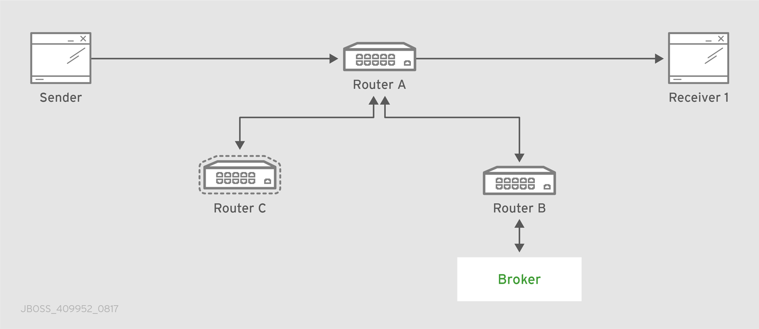
The "Router.A" configuration is something like following.
router {
    mode: interior
    id: Router.A
}

listener {
    host: 0.0.0.0
    port: 6000
    authenticatePeer: no
}

connector {
    name: INTER_ROUTER_B
    addr: 127.0.0.1
    port: 5001
    role: inter-router
}

connector {
    name: INTER_ROUTER_C
    addr: 127.0.0.1
    port: 5002
    role: inter-router
}
There is only one listener in order to accept client connections and two connector entities for connecting to the other two routers.
The "Router.B" configuration is the following.
router {
    mode: interior
    id: Router.B
}

listener {
    addr: 0.0.0.0
    port: 5001
    authenticatePeer: no
    role: inter-router
}

listener {
    host: 0.0.0.0
    port: 6001
    authenticatePeer: no
}
It has two listener entities in order to listen for connections from clients and from other routers in the network (in this case from the "Router.A" and "Router.C").
Finally, quite similar is the "Router.C" configuration.
router {
    mode: interior
    id: Router.C
}

listener {
    addr: 0.0.0.0
    port: 5002
    authenticatePeer: no
    role: inter-router
}

listener {
    host: 0.0.0.0
    port: 6002
    authenticatePeer: no
}

connector {
    name: INTER_ROUTER_B
    addr: 127.0.0.1
    port: 5001
    role: inter-router
}
It has two listener entities in order to listen for connections from clients and from other routers in the network (in this case from the "Router.A") and finally it has a connector (for connecting to the "Router.B")
Consider a sender client connected to "Router.A" and attached to my_address address which start to send messages (that is, 10 messages) and a receiver client connected to the "Router.B" and attached to the same address.
Starting the receiver, it waits for messages with no output on the console.
# python simple_recv.py -a localhost:6001/my_queue -m 10
Starting the sender, all the messages flow through "Router.A" and "Router.B" reaching the receiver; at this point the messages are all confirmed at sender side.
# python simple_send.py -a localhost:6001/my_queue -m 10
all messages confirmed
At same time, the receivers shows the messages received through the "Router.B".
{u'sequence': 1L}
{u'sequence': 2L}
{u'sequence': 3L}
{u'sequence': 4L}
{u'sequence': 5L}
{u'sequence': 6L}
{u'sequence': 7L}
{u'sequence': 8L}
{u'sequence': 9L}
{u'sequence': 10L}
The path redundancy is provided by the other available path through the "Router.A", "Router.C" and then "Router.B". It means that if the connection between "Router.A" and "Router.B" goes down, the alternative path is used to reach the receiver.
Now, consider a fault on the "Router.B"; the receiver is not reachable anymore on that path but it can connect to the "Router.C" in order to continue to receive messages from the sender which does not know what’s happened and it can continue to send messages to the "Router.A" in order to reach the receiver.
Figure 10.2. Path Redundancy after Router Failure

The receiver is still reachable in order to get messages from the sender as displayed in the console output.
# python simple_recv.py -a localhost:6002/my_queue -m 10
{u'sequence': 1L}
{u'sequence': 2L}
{u'sequence': 3L}
{u'sequence': 4L}
{u'sequence': 5L}
{u'sequence': 6L}
{u'sequence': 7L}
{u'sequence': 8L}
{u'sequence': 9L}
{u'sequence': 10L}
10.2. Path Redundancy and Temporal Decoupling
In order to have temporal decoupling in a solution based on AMQ Interconnect, adding one or more brokers is a must for its "store and forward" feature. Choosing the right topology, it is possible to have a solution which offers reliability with both path redundancy and permanent storing for messages.
Consider the following simple scenario :
- a network with three routers "Router.A", "Router.B" and "Router.C" and finally a broker.
- the "Router.A" is connected to both "Router.B" and "Router.C".
- initially only the "Router.B" is connected to the broker.
- all three routers listen for client connections.
- a sender client connects to the "Router.A" in order to send messages to a queue in the broker.
- a receiver client connects to the "Router.A" in order to get messages from the queue in the broker.
Figure 10.3. Path Redundancy and Temporal Decoupling Enabled Topology
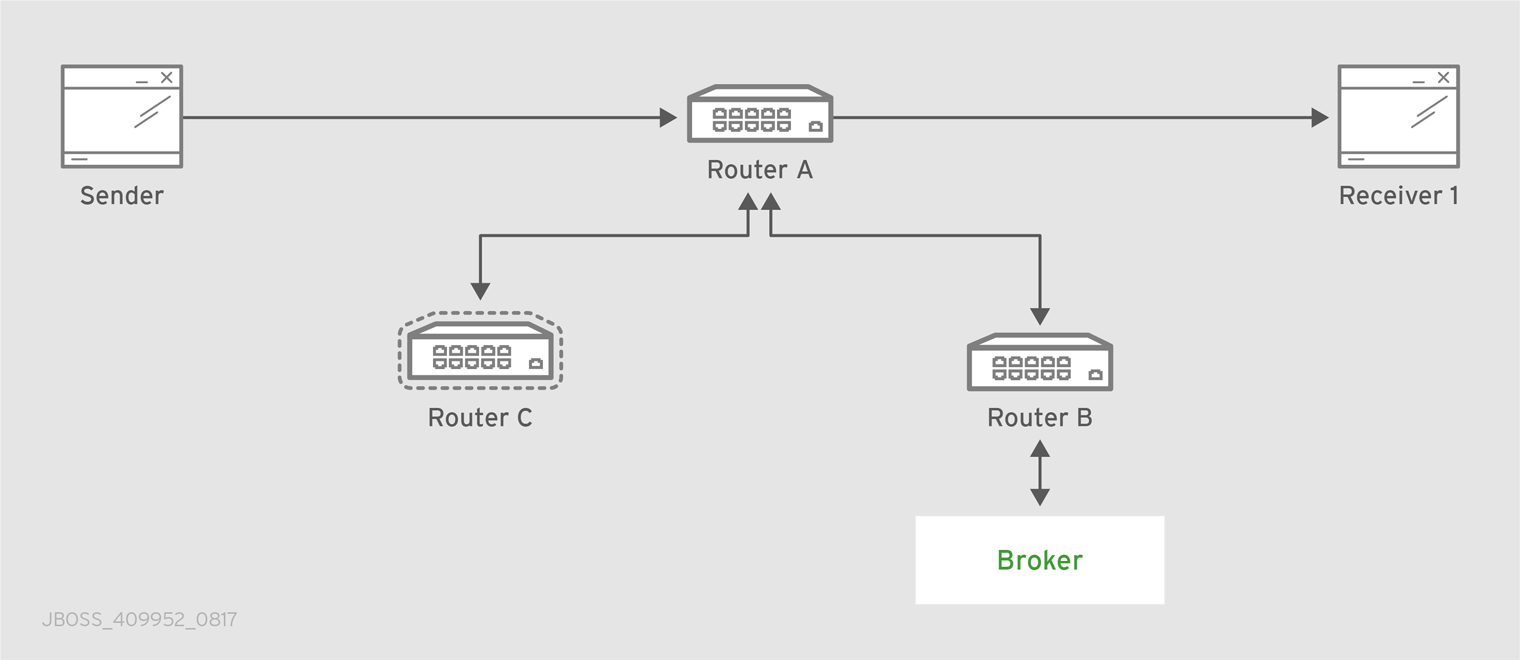
The receiver client can be offline when the sender starts to send messages because they’ll be stored into the queue permanently; coming back online, the receiver can get messages from the queue itself without message loss.
The "Router.A" configuration is something like following.
router {
    mode: interior
    id: Router.A
}

listener {
    host: 0.0.0.0
    port: 6000
    authenticatePeer: no
}

connector {
    name: INTER_ROUTER_B
    addr: 127.0.0.1
    port: 5001
    role: inter-router
}

connector {
    name: INTER_ROUTER_C
    addr: 127.0.0.1
    port: 5002
    role: inter-router
}

address {
    prefix: my_queue
    waypoint: yes
}
It has a listener for accepting incoming connections from clients and two connector entities in order to connect to the other routers. The queue named my_queue on the broker is exposed by a waypoint.
The "Router.B" configuration is the following.
router {
    mode: interior
    id: Router.B
}

listener {
    addr: 0.0.0.0
    port: 5001
    authenticatePeer: no
    role: inter-router
}

listener {
    host: 0.0.0.0
    port: 6001
    authenticatePeer: no
}

connector {
    name: BROKER
    addr: 127.0.0.1
    port: 5672
    role: route-container
}

address {
    prefix: my_queue
    waypoint: yes
}

autoLink {
    addr: my_queue
    connection: BROKER
    dir: in
}

autoLink {
    addr: my_queue
    connection: BROKER
    dir: out
}
It can accept incoming connections from clients and from other routers (in this case the "Router.A") and connects to the broker. The queue named my_queue on the broker is exposed by a waypoint with the related auto-links in both directions in order to send and receive messages to/from the queue itself.
Finally, the simple "Router.C" configuration.
router {
    mode: interior
    id: Router.C
}

listener {
    addr: 0.0.0.0
    port: 5002
    authenticatePeer: no
    role: inter-router
}

listener {
    host: 0.0.0.0
    port: 6002
    authenticatePeer: no
}
It can accept incoming connections from clients and from other routers (in this case the "Router.A"). Initially there is no connection between this router and the broker.
First of all, thanks to the broker and its "store and forward" feature, the sender can connect to the "Router.A" and start to send messages even if the receiver is not online in that moment. Using the Python sample from the Qpid Proton library, the console output is like following.
# python simple_send.py -a localhost:6000/my_queue -m 10
all messages confirmed
All messages are confirmed because they reached the queue inside the broker through "Router.A" and "Router.B"; it is confirmed using the qdstat tool.
# qdstat -b localhost:6001 -a
Router Addresses
  class   addr                   phs  distrib    in-proc  local  remote  cntnr  in  out  thru  to-proc  from-proc
  =================================================================================================================
  local   $_management_internal       closest    1        0      0       0      0   0    0     0        0
  local   $displayname                closest    1        0      0       0      0   0    0     0        0
  mobile  $management            0    closest    1        0      0       0      1   0    0     1        0
  local   $management                 closest    1        0      0       0      0   0    0     0        0
  router  Router.A                    closest    0        0      1       0      0   0    6     0        6
  router  Router.C                    closest    0        0      1       0      0   0    4     0        4
  mobile  my_queue               1    balanced   0        0      0       0      0   0    0     0        0
  mobile  my_queue               0    balanced   0        1      0       0      0   10   0     0        0
  local   qdhello                     flood      1        1      0       0      0   0    0     97       117
  local   qdrouter                    flood      1        0      0       0      0   0    0     7        0
  topo    qdrouter                    flood      1        0      2       0      0   0    8     13       9
  local   qdrouter.ma                 multicast  1        0      0       0      0   0    0     2        0
  topo    qdrouter.ma                 multicast  1        0      2       0      0   0    0     0        1
  local   temp.7f2u0zv9_U6QC5e        closest    0        1      0       0      0   0    0     0        0
For the "Router.B", there are 10 messages as output (from the router to the broker) on the my_queue address.
Starting the receiver connected to the "Router.A", it gets all the available messages from the queue.
# python simple_recv.py -a localhost:6000/my_queue -m 10
{u'sequence': 1L}
{u'sequence': 2L}
{u'sequence': 3L}
{u'sequence': 4L}
{u'sequence': 5L}
{u'sequence': 6L}
{u'sequence': 7L}
{u'sequence': 8L}
{u'sequence': 9L}
{u'sequence': 10L}
Using the qdstat tool on the "Router.B" another time, the output is like following.
# qdstat -b localhost:6001 -a
Router Addresses
  class   addr                   phs  distrib    in-proc  local  remote  cntnr  in  out  thru  to-proc  from-proc
  =================================================================================================================
  local   $_management_internal       closest    1        0      0       0      0   0    0     0        0
  local   $displayname                closest    1        0      0       0      0   0    0     0        0
  mobile  $management            0    closest    1        0      0       0      2   0    0     2        0
  local   $management                 closest    1        0      0       0      0   0    0     0        0
  router  Router.A                    closest    0        0      1       0      0   0    6     0        6
  router  Router.C                    closest    0        0      1       0      0   0    4     0        4
  mobile  my_queue               1    balanced   0        0      0       0      10  0    10    0        0
  mobile  my_queue               0    balanced   0        1      0       0      0   10   0     0        0
  local   qdhello                     flood      1        1      0       0      0   0    0     156      182
  local   qdrouter                    flood      1        0      0       0      0   0    0     7        0
  topo    qdrouter                    flood      1        0      2       0      0   0    10    18       11
  local   qdrouter.ma                 multicast  1        0      0       0      0   0    0     2        0
  topo    qdrouter.ma                 multicast  1        0      2       0      0   0    0     2        1
  local   temp.Xov_ZUcyti3jjXY        closest    0        1      0       0      0   0    0     0        0
For the "Router.B", there are 10 messages as input (from the broker to the router) on the my_queue address.
Now, consider a fault on the "Router.B"; in this case the broker is not reachable but it is possible to set up path redundancy through the "Router.C".
Figure 10.4. Path Redundancy and Temporal Decoupling after Router Failure
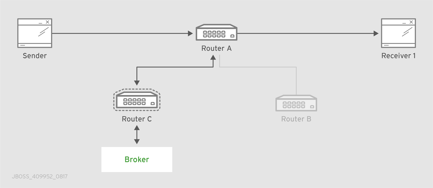
Using the qdmanage tool, it is possible to configure the waypoint on my_queue address, the related auto-links in both directions and finally the connector instance in order to enable the connection to the broker.
[root@localhost /]# qdmanage -b localhost:6002 create --stdin
[
{ "type":"connector", "name":"BROKER", "port":5672, "role":"route-container" },
{ "type":"address", "prefix":"my_queue", "waypoint":"yes" },
{ "type":"autoLink", "addr":"my_queue", "connection":"BROKER", "dir":"in" },
{ "type":"autoLink", "addr":"my_queue", "connection":"BROKER", "dir":"out" }
]
[
  {
    "verifyHostName": true,
    "stripAnnotations": "both",
    "name": "BROKER",
    "allowRedirect": true,
    "idleTimeoutSeconds": 16,
    "maxFrameSize": 65536,
    "host": "127.0.0.1",
    "cost": 1,
    "role": "route-container",
    "maxSessions": 32768,
    "type": "org.apache.qpid.dispatch.connector",
    "port": "5672",
    "identity": "connector/127.0.0.1:5672:BROKER",
    "addr": "127.0.0.1"
  },
  {
    "name": null,
    "prefix": "my_queue",
    "ingressPhase": 0,
    "waypoint": false,
    "distribution": "balanced",
    "type": "org.apache.qpid.dispatch.router.config.address",
    "identity": "7",
    "egressPhase": 0
  },
  {
    "addr": "my_queue",
    "name": null,
    "linkRef": null,
    "type": "org.apache.qpid.dispatch.router.config.autoLink",
    "operStatus": "inactive",
    "connection": "BROKER",
    "dir": "in",
    "phase": 1,
    "lastError": null,
    "externalAddr": null,
    "identity": "8",
    "containerId": null
  },
  {
    "addr": "my_queue",
    "name": null,
    "linkRef": null,
    "type": "org.apache.qpid.dispatch.router.config.autoLink",
    "operStatus": "inactive",
    "connection": "BROKER",
    "dir": "out",
    "phase": 0,
    "lastError": null,
    "externalAddr": null,
    "identity": "9",
    "containerId": null
  }
]
The "Router.C" configuration changes in the same way as "Router.B". It can accept incoming connections from clients and from other routers (in this case the "Router.A") and connects to the broker. The queue named my_queue on the broker is exposed by a waypoint with the related auto-links in both directions in order to send and receive messages to/from the queue itself.
At this point, the sender can connect to the "Router.A" for sending messages to the queue in the broker thanks to the "Router.C".
# python simple_send.py -a localhost:6000/my_queue -m 10
all messages confirmed
All messages are confirmed because they reached the queue inside the broker through "Router.A" and "Router.C"; it is confirmed using the qdstat tool.
# qdstat -b localhost:6002 -a
Router Addresses
  class   addr                   phs  distrib    in-proc  local  remote  cntnr  in  out  thru  to-proc  from-proc
  =================================================================================================================
  local   $_management_internal       closest    1        0      0       0      0   0    0     1        1
  local   $displayname                closest    1        0      0       0      0   0    0     0        0
  mobile  $management            0    closest    1        0      0       0      5   0    0     5        0
  local   $management                 closest    1        0      0       0      0   0    0     0        0
  router  Router.A                    closest    0        0      1       0      0   0    5     0        5
  mobile  my_queue               0    balanced   0        1      0       0      0   10   0     0        0
  mobile  my_queue               1    balanced   0        0      0       0      0   0    0     0        0
  local   qdhello                     flood      1        1      0       0      0   0    0     665      647
  local   qdrouter                    flood      1        0      0       0      0   0    0     8        0
  topo    qdrouter                    flood      1        0      1       0      0   0    31    52       32
  local   qdrouter.ma                 multicast  1        0      0       0      0   0    0     1        0
  topo    qdrouter.ma                 multicast  1        0      1       0      0   0    1     2        1
  local   temp.k6UMaS4P0JmtSlL        closest    0        1      0       0      0   0    0     0        0
For the "Router.C", there are 10 messages as output (from the router to the broker) on the my_queue address.
Starting the receiver connected to the "Router.A", it gets all the available messages from the queue.
# python simple_recv.py -a localhost:6000/my_queue -m 10
{u'sequence': 1L}
{u'sequence': 2L}
{u'sequence': 3L}
{u'sequence': 4L}
{u'sequence': 5L}
{u'sequence': 6L}
{u'sequence': 7L}
{u'sequence': 8L}
{u'sequence': 9L}
{u'sequence': 10L}
Using the qdstat tool on the "Router.C" another time, the output is like following.
# qdstat -b localhost:6002 -a
Router Addresses
  class   addr                   phs  distrib    in-proc  local  remote  cntnr  in  out  thru  to-proc  from-proc
  =================================================================================================================
  local   $_management_internal       closest    1        0      0       0      0   0    0     1        1
  local   $displayname                closest    1        0      0       0      0   0    0     0        0
  mobile  $management            0    closest    1        0      0       0      6   0    0     6        0
  local   $management                 closest    1        0      0       0      0   0    0     0        0
  router  Router.A                    closest    0        0      1       0      0   0    5     0        5
  mobile  my_queue               0    balanced   0        1      0       0      0   10   0     0        0
  mobile  my_queue               1    balanced   0        0      0       0      10  0    10    0        0
  local   qdhello                     flood      1        1      0       0      0   0    0     746      726
  local   qdrouter                    flood      1        0      0       0      0   0    0     8        0
  topo    qdrouter                    flood      1        0      1       0      0   0    34    55       35
  local   qdrouter.ma                 multicast  1        0      0       0      0   0    0     1        0
  topo    qdrouter.ma                 multicast  1        0      1       0      0   0    1     4        1
  local   temp.Hso3moy3l+Sn+Fy        closest    0        1      0       0      0   0    0     0        0
For the "Router.C", there are 10 messages as input (from the broker to the router) on the my_queue address.
10.3. Sharded Queue
Every broker has limits in terms of queue size but in order to overcome this problem, one possible solution is "sharding" queues : in that way a single queue is divided in more "shards" (chunks) each on a different broker. It means that such solution needs more than one broker instance in order to host a shard on each of them. Of course, a sender connected to one of these brokers can send messages to the shard hosted only on that broker. At same time, a receiver connected to a broker can get messages from the shard that is hosted on that broker and can not see available messages in the shards hosted on the other brokers, even if they are all parts of the same queue.
Even if speaking about shards it is obvious that they are real queues all with same name but on different brokers. The "shard" concept is an abstract one because finally a shard is a real queue stored on a broker.
The big problem in this scenario, designed only with brokers, is that a receiver can be stucked on an empty shard without reading any messages while the shards on the other brokers have messages to deliver. it is a real problem because the receiver is interested in receiving messages from the whole queue and it does not take care if it is shared or not. Because of this problem, the receiver sees the queue as empty even if it is not so true due to the sharding and the messages available on the other shards.
The above problem can be solved adding a AMQ Interconnect instance in the network in front of the brokers and leverage on its waypoint feature with related auto-links.
Consider the following simple scenario :
- a network with one router "Router.A" and two brokers.
- the "Router.A" listens for clients connections and it is connected to both brokers.
- the brokers host shards for a queue; each broker has one shard.
- a sender client connects to the "Router.A" in order to send messages to the queue.
- a receiver client connects to the "Router.A" in order to get messages from the queue.
Figure 10.5. Sharded Queue Enabled Topology

With such solution and connecting to the "Router.A", sender and receiver do not know anything about sharding; they want send and receive messages to/from the whole queue that is the only thing they are aware of. They are both connected to the router and see only one address (related to the queue).
The "Router.A" configuration is something like following.
router {
    mode: standalone
    id: Router.A
}

listener {
    host: 0.0.0.0
    port: 6000
    authenticatePeer: no
}

connector {
    name: BROKER1
    addr: 127.0.0.1
    port: 5672
    role: route-container
}

connector {
    name: BROKER2
    addr: 127.0.0.1
    port: 5673
    role: route-container
}

address {
    prefix: my_queue
    waypoint: yes
}

autoLink {
    addr: my_queue
    connection: BROKER1
    dir: in
}

autoLink {
    addr: my_queue
    connection: BROKER1
    dir: out
}

autoLink {
    addr: my_queue
    connection: BROKER2
    dir: in
}

autoLink {
    addr: my_queue
    connection: BROKER2
    dir: out
}
The router has a listener for incoming connection from clients and two connector instances in order to connect to both brokers. The whole queue is named my_queue hosted in terms of shards on both brokers and the router is configured with a waypoint for that address. Finally, there are two auto-links in both directions for that queue on both brokers.
Using the Python sample from the Qpid Proton library, the sender can connect to the "Router.A" and start to send messages to the queue; the console output is like following.
# python simple_send.py -a localhost:6000/my_queue -m 10
all messages confirmed
All messages are confirmed because they reached the queue and, thanks to the default balanced distribution on the address, the messages are delivered to both shards on the brokers (5 messages per shard). Using the qdstat tool on the router, the distribution is clear.
# qdstat -b localhost:6000 -l
Router Links
  type      dir  conn id  id  peer  class   addr                  phs  cap  undel  unsettled  deliveries  admin    oper
  =======================================================================================================================
  endpoint  in   1        6         mobile  my_queue              1    250  0      0          0           enabled  up
  endpoint  out  1        7         mobile  my_queue              0    250  0      0          5           enabled  up
  endpoint  in   2        8         mobile  my_queue              1    250  0      0          0           enabled  up
  endpoint  out  2        9         mobile  my_queue              0    250  0      0          5           enabled  up
  endpoint  in   8        19        mobile  $management           0    250  0      0          1           enabled  up
  endpoint  out  8        20        local   temp.qCGHruCa4UIvYrS       250  0      0          0           enabled  up
There are the out links (from router to brokers) for the my_queue address (id values 7 and 9) which have each 5 deliveries. It shows messages distributed across brokers and related shards for the queue; it is confirmed by the different connections they are tied (conn id values 1 and 2).
Starting the receiver connected to the "Router.A", it gets all the available messages from the queue.
# python simple_recv.py -a localhost:6000/my_queue -m 10
{u'sequence': 1L}
{u'sequence': 2L}
{u'sequence': 3L}
{u'sequence': 4L}
{u'sequence': 5L}
{u'sequence': 6L}
{u'sequence': 7L}
{u'sequence': 8L}
{u'sequence': 9L}
{u'sequence': 10L}
As for the sender, they are received through both the brokers and related shards. it is confirmed using the qdstat tool.
# qdstat -b localhost:6000 -l
Router Links
  type      dir  conn id  id  peer  class   addr                  phs  cap  undel  unsettled  deliveries  admin    oper
  =======================================================================================================================
  endpoint  in   1        6         mobile  my_queue              1    250  0      0          5           enabled  up
  endpoint  out  1        7         mobile  my_queue              0    250  0      0          5           enabled  up
  endpoint  in   2        8         mobile  my_queue              1    250  0      0          5           enabled  up
  endpoint  out  2        9         mobile  my_queue              0    250  0      0          5           enabled  up
  endpoint  in   10       22        mobile  $management           0    250  0      0          1           enabled  up
  endpoint  out  10       23        local   temp.HT+f3ZilGP5o3wo       250  0      0          0           enabled  up
There are the in links (from brokers to router) for the my_queue address (id values 6 and 8) which have each 5 deliveries. It shows messages distributed across brokers and related shards for the queue; it is confirmed by the different connections they are tied (conn id values 1 and 2).
One disadvantage of sharded queues is that the receiver might receive messages "out of order" even with very good performance.
Appendix A. Using Cyrus SASL to Provide Authentication
AMQ Interconnect uses the Cyrus SASL library for SASL authentication. Therefore, if you want to use SASL, you must set up the Cyrus SASL database and configure it.
A.1. Generating a SASL Database
To generate a SASL database to store credentials, enter the following command:
# saslpasswd2 -c -f SASL_DATABASE_NAME.sasldb -u DOMAIN_NAME USER_NAME
This command creates or updates the specified SASL database, and adds the specified user name to it. The command also prompts you for the user name’s password.
The full user name is the user name you entered plus the domain name (USER_NAME@DOMAIN_NAME). Providing a domain name is not required when you add a user to the database, but if you do not provide one, a default domain will be added automatically (the hostname of the machine on which the tool is running). For example, in the command above, the full user name would be user1@domain.com.
A.2. Viewing Users in a SASL Database
To view the user names stored in the SASL database:
# sasldblistusers2 -f qdrouterd.sasldb
user2@domain.com: PASSWORD
user1@domain.com: PASSWORD
A.3. Configuring a SASL Database
To use the SASL database to provide authentication in AMQ Interconnect:
-
Open the
/etc/sasl2/qdrouterd.confconfiguration file. Set the following attributes:
pwcheck_method: auxprop
auxprop_plugin: sasldb
sasldb_path: SASL_DATABASE_NAME
mech_list: MECHANISM1 ...
sasldb_pathThe name of the SASL database to use.
For example:
sasldb_path: qdrouterd.sasldb
mech_listThe SASL mechanisms to enable for authentication. To add multiple mechanisms, separate each entry with a space.
For example:
mech_list: ANONYMOUS DIGEST-MD5 EXTERNAL PLAIN
Appendix B. Configuration Reference
The AMQ Interconnect component behavior is totally configurable using a configuration file which can be passed as parameter (with the --conf option) on the command line when running it. After installation, a default configuration file is placed at the following path :
[install-prefix]/etc/qpid-dispatch/qdrouterd.conf
This file is used when the router is started without specify configuration file path on the command line and when it is started as a service. In case of starting router on the command line the configuration file can be placed anywhere on the file system.
B.1. Configuration File
The configuration file is made up of sections with following syntax :
sectionName {
    attributeName: attributeValue
    attributeName: attributeValue
    ...
}
A section could be referenced by another section using its name attribute. An example is the sslProfile section which describes attributes for setting SSL/TLS configuration and can be applied to one or more listener and connector sections.
sslProfile {
    name: ssl-profile-one
    certDb: ca-certificate-1.pem
    certFile: server-certificate-1.pem
    keyFile: server-private-key.pem
}

listener {
    sslProfile: ssl-profile-one
    host: 0.0.0.0
    port: amqp
    saslMechanisms: ANONYMOUS
}
In the above example, the sslProfile section named ssl-profile-one is used to define the sslProfile attribute for the listener section.
B.1.1. Configuration Sections
B.1.1.1. sslProfile
Attributes for setting SSL/TLS configuration for connections.
- certDb (path) : The absolute path to the database that contains the public certificates of trusted certificate authorities (CA).
- certFile (path) : The absolute path to the file containing the PEM-formatted public certificate to be used on the local end of any connections using this profile.
- keyFile (path) : The absolute path to the file containing the PEM-formatted private key for the above certificate.
- passwordFile (path) : If the above private key is password protected, this is the absolute path to a file containing the password that unlocks the certificate key.
- password (string) : An alternative to storing the password in a file referenced by passwordFile is to supply the password right here in the configuration file. This option can be used by supplying the password in the ‘password’ option. Don’t use both password and passwordFile in the same profile.
- uidFormat (string) : A list of x509 client certificate fields that will be used to build a string that will uniquely identify the client certificate owner. For example, a value of ‘cou’ indicates that the uid will consist of c - common name concatenated with o - organization-company name concatenated with u - organization unit; or a value of ‘oF’ indicates that the uid will consist of o (organization name) concatenated with F (the sha256 fingerprint of the entire certificate) . Allowed values can be any combination of comma separated ‘c’( ISO3166 two character country code), ‘s’(state or province), ‘l’(Locality; generally - city), ‘o’(Organization - Company Name), ‘u’(Organization Unit - typically certificate type or brand), ‘n’(CommonName - typically a username for client certificates) and ‘1’(sha1 certificate fingerprint, as displayed in the fingerprints section when looking at a certificate with say a web browser is the hash of the entire certificate) and 2 (sha256 certificate fingerprint) and 5 (sha512 certificate fingerprint).
- displayNameFile (string) : The absolute path to the file containing the unique id to display name mapping.
- name (string) : The name of the profile used for referencing it from listener and connector sections.
Used by : listener, connector.
B.1.1.2. router
Describe main information about the router related to identity, internal processes and inter routers communication.
- id (string) : Router’s unique identity. It is required and the router will fail to start without it.
-
mode (One of [
standalone,interior], default=standalone) : In standalone mode, the router operates as a single component. It does not participate in the routing protocol and therefore will not cooperate with other routers. In interior mode, the router operates in cooperation with other interior routers in an interconnected network. -
helloInterval (integer, default=
1) : Interval in seconds between HELLO messages sent to neighbor routers in order to announce its presence (as a keep alive). -
helloMaxAge (integer, default=
3) : Time in seconds after which a neighbor router is declared lost if no HELLO is received. -
raInterval (integer, default=
30) : Interval in seconds between Router-Advertisements sent to all routers in a stable network. -
raIntervalFlux (integer, default=
4) : Interval in seconds between Router-Advertisements sent to all routers during topology fluctuations. -
remoteLsMaxAge (integer, default=
60) : Time in seconds after which link state is declared stale if no RA is received. -
workerThreads (integer, default=
4) : The number of threads that will be created to process message traffic and other application work (timers, non-amqp file descriptors, and so on). - debugDump (path) : The absolute path for a file to dump debugging information that can’t be logged normally.
- saslConfigPath (path) : The absolute path to the SASL configuration file.
-
saslConfigName (string, default=
qdrouterd) : Name of the SASL configuration. This string + ‘.conf’ is the name of the configuration file.
B.1.1.3. listener
Listens for incoming connections to the router.
-
host (string, default=
127.0.0.1) : IP address: ipv4 or ipv6 literal or a hostname. -
port (string, default=
amqp) : Port number or symbolic service name. -
protocolFamily (One of [
IPv4,IPv6]) : IPv4: Internet Protocol version 4; IPv6: Internet Protocol version 6. If not specified, the protocol family will be automatically determined from the address. -
role (One of [
normal,inter-router,route-container], default=normal) : The role of an established connection. In the normal role, the connection is assumed to be used for AMQP clients that are doing normal message delivery over the connection. In the inter-router role, the connection is assumed to be to another router in the network. Inter-router discovery and routing protocols can only be used over inter-router connections. The route-container role can be used for router-container connections, for example, a router-broker connection. -
cost (integer, default=
1) : For theinter-routerole only. This value assigns a cost metric to the inter-router connection. The default (and minimum) value is one. Higher values represent higher costs. The cost is used to influence the routing algorithm as it attempts to use the path with the lowest total cost from ingress to egress. - saslMechanisms (string) : Space separated list of accepted SASL authentication mechanisms.
- authenticatePeer (boolean) : yes: Require the peer’s identity to be authenticated; no: Do not require any authentication.
- requireEncryption (boolean) : yes: Require the connection to the peer to be encrypted; no: Permit non-encrypted communication with the peer. It is related to SASL mechanisms which support encryption.
- requireSsl (boolean) : yes: Require the use of SSL/TLS on the connection; no: Allow clients to connect without SSL/TLS.
- trustedCerts (path) : This optional setting can be used to reduce the set of available CAs for client authentication. If used, this setting must provide an absolute path to a PEM file that contains the trusted certificates.
-
maxFrameSize (integer, default=
16384) : Defaults to 16384. If specified, it is the maximum frame size in octets that will be used in the connection-open negotiation with a connected peer. The frame size is the largest contiguous set of uninterrupted data that can be sent for a message delivery over the connection. Interleaving of messages on different links is done at frame granularity. -
idleTimeoutSeconds : (integer, default=
16) : The idle timeout, in seconds, for connections through this listener. If no frames are received on the connection for this time interval, the connection shall be closed. -
stripAnnotations (One of [
in,out,both,no], default=both) : in: Strip the dispatch router specific annotations only on ingress; out: Strip the dispatch router specific annotations only on egress; both: Strip the dispatch router specific annotations on both ingress and egress; no - do not strip dispatch router specific annotations. - linkCapacity (integer) : The capacity of links within this connection, in terms of message deliveries. The capacity is the number of messages that can be in-flight concurrently for each link.
- sslProfile (string) : The name of the sslProfile entity to use in order to have SSL/TLS configuration.
-
http (boolean): If set to
yes, the listener will accept HTTP connections using AMQP over WebSockets.
B.1.1.4. connector
Establishes an outgoing connection from the router.
- name (string) : Name using to reference the connector in the configuration file for example for a link routing to queue on a broker.
-
host (string, default=
127.0.0.1) : IP address: ipv4 or ipv6 literal or a hostname. -
port (string, default=
amqp) : Port number or symbolic service name. -
protocolFamily (One of [
IPv4,IPv6]) : IPv4: Internet Protocol version 4; IPv6: Internet Protocol version 6. If not specified, the protocol family will be automatically determined from the address. -
role (One of [
normal,inter-router,route-container], default=normal) : The role of an established connection. In the normal role, the connection is assumed to be used for AMQP clients that are doing normal message delivery over the connection. In the inter-router role, the connection is assumed to be to another router in the network. Inter-router discovery and routing protocols can only be used over inter-router connections. route-container role can be used for router-container connections, for example, a router-broker connection. -
cost (integer, default=
1) : For the ‘inter-router’ role only. This value assigns a cost metric to the inter-router connection. The default (and minimum) value is one. Higher values represent higher costs. The cost is used to influence the routing algorithm as it attempts to use the path with the lowest total cost from ingress to egress. - saslMechanisms (string) : Space separated list of accepted SASL authentication mechanisms.
- allowRedirect (boolean, default=True) : Allow the peer to redirect this connection to another address.
-
maxFrameSize (integer, default=
65536) : Maximum frame size in octets that will be used in the connection-open negotiation with a connected peer. The frame size is the largest contiguous set of uninterrupted data that can be sent for a message delivery over the connection. Interleaving of messages on different links is done at frame granularity. -
idleTimeoutSeconds (integer, default=
16) : The idle timeout, in seconds, for connections through this connector. If no frames are received on the connection for this time interval, the connection shall be closed. -
stripAnnotations (One of [
in,out,both,no], default=both) : in: Strip the dispatch router specific annotations only on ingress; out: Strip the dispatch router specific annotations only on egress; both: Strip the dispatch router specific annotations on both ingress and egress; no - do not strip dispatch router specific annotations. - linkCapacity (integer) : The capacity of links within this connection, in terms of message deliveries. The capacity is the number of messages that can be in-flight concurrently for each link.
- verifyHostName (boolean, default=True) : yes: Ensures that when initiating a connection (as a client) the hostname in the URL to which this connector connects to matches the hostname in the digital certificate that the peer sends back as part of the SSL/TLS connection; no: Does not perform hostname verification
- saslUsername (string) : The username that the connector is using to connect to a peer.
- saslPassword (string) : The password that the connector is using to connect to a peer.
- sslProfile (string) : The name of the sslProfile entity to use in order to have SSL/TLS configuration.
B.1.1.5. log
Configure logging for a particular module which is part of the router. You can use the UPDATE operation to change log settings while the router is running.
-
module (One of [
ROUTER,ROUTER_CORE,ROUTER_HELLO,ROUTER_LS,ROUTER_MA,MESSAGE,SERVER,AGENT,CONTAINER,ERROR,POLICY,DEFAULT], required) : Module to configure. The special moduleDEFAULTspecifies defaults for all modules. -
enable (string, default=
default, required) Levels are:trace,debug,info,notice,warning,error,critical. The enable string is a comma-separated list of levels. A level may have a trailing+to enable that level and above. For exampletrace,debug,warning+means enable trace, debug, warning, error and critical. The value ‘none’ means disable logging for the module. The valuedefaultmeans use the value from theDEFAULTmodule. - timestamp (boolean) : Include timestamp in log messages.
- source (boolean) : Include source file and line number in log messages.
-
output (string) : Where to send log messages. Can be
stderr,syslogor a file name.
B.1.1.6. address
Entity type for address configuration. This is used to configure the treatment of message-routed deliveries within a particular address-space. The configuration controls distribution and address phasing.
- prefix (string, required) : The address prefix for the configured settings.
-
distribution (One of [
multicast,closest,balanced], default=balanced) : Treatment of traffic associated with the address. - waypoint (boolean) : Designates this address space as being used for waypoints. This will cause the proper address-phasing to be used.
- ingressPhase (integer) : Advanced - Override the ingress phase for this address.
- egressPhase (integer) : Advanced - Override the egress phase for this address.
B.1.1.7. linkRoute
Entity type for link-route configuration. This is used to identify remote containers that shall be destinations for routed link-attaches. The link-routing configuration applies to an addressing space defined by a prefix.
- prefix (string, required) : The address prefix for the configured settings.
- containerId (string) : it specifies that the link route will be activated if a remote container will provide a container-id matching with this value.
- connection (string) : The name from a connector or listener.
-
distribution (One of [
linkBalanced], default=linkBalanced) : Treatment of traffic associated with the address. -
dir (One of [
in,out], required) : The permitted direction of links. It is defined from a router point of view so ‘in’ means client senders (router ingress) and ‘out’ means client receivers (router egress).
B.1.1.8. autoLink
Entity type for configuring auto-links. Auto-links are links whose lifecycle is managed by the router. These are typically used to attach to waypoints on remote containers (brokers, and so on.).
- addr (string, required) : The address of the provisioned object.
-
dir (One of [
in,out], required) : The direction of the link to be created. In means into the router, out means out of the router. -
phase (integer) : The address phase for this link. Defaults to
0foroutlinks and1forinlinks. - containerId (string) : ContainerID for the target container.
- connection (string) : The name from a connector or listener.
B.1.1.9. console
Start a websocket/tcp proxy and http file server to serve the web console.
- listener (string) : The name of the listener to send the proxied tcp traffic to.
-
wsport (integer, default=
5673) : The port on which to listen for websocket traffic. - proxy (string) : The full path to the proxy program to run.
- home (string) : The full path to the html/css/js files for the console.
- args (string) : Optional args to pass to the proxy program for logging, authentication, and so on.
B.1.1.10. policy
Defines global connection limit
- maximumConnections (integer) : Global maximum number of concurrent client connections allowed. Zero implies no limit. This limit is always enforced even if no other policy settings have been defined.
- enableAccessRules (boolean) : Enable user rule set processing and connection denial.
- policyFolder (path) : The absolute path to a folder that holds policyRuleset definition .json files. For a small system the rulesets may all be defined in this file. At a larger scale it is better to have the policy files in their own folder and to have none of the rulesets defined here. All rulesets in all .json files in this folder are processed.
- defaultApplication (string) : Application policyRuleset to use for connections with no open.hostname or a hostname that does not match any existing policy. For users that don’t wish to use open.hostname or any multi-tennancy feature, this default policy can be the only policy in effect for the network.
- defaultApplicationEnabled (boolean) : Enable defaultApplication policy fallback logic.
B.1.1.11. policyRuleset
Per application definition of the locations from which users may connect and the groups to which users belong.
- maxConnections (integer) : Maximum number of concurrent client connections allowed. Zero implies no limit.
- maxConnPerUser (integer) : Maximum number of concurrent client connections allowed for any single user. Zero implies no limit.
- maxConnPerHost (integer) : Maximum number of concurrent client connections allowed for any remote host. Zero implies no limit.
- userGroups (map) : A map where each key is a user group name and the corresponding value is a CSV string naming the users in that group. Users who are assigned to one or more groups are deemed ‘restricted’. Restricted users are subject to connection ingress policy and are assigned policy settings based on the assigned user groups. Unrestricted users may be allowed or denied. If unrestricted users are allowed to connect then they are assigned to user group default.
- ingressHostGroups (map) : A map where each key is an ingress host group name and the corresponding value is a CSV string naming the IP addresses or address ranges in that group. IP addresses may be FQDN strings or numeric IPv4 or IPv6 host addresses. A host range is two host addresses of the same address family separated with a hyphen. The wildcard host address ‘*’ represents any host address.
- ingressPolicies (map) : A map where each key is a user group name and the corresponding value is a CSV string naming the ingress host group names that restrict the ingress host for the user group. Users who are members of the user group are allowed to connect only from a host in one of the named ingress host groups.
- connectionAllowDefault (boolean) : Unrestricted users, those who are not members of a defined user group, are allowed to connect to this application. Unrestricted users are assigned to the ‘default’ user group and receive ‘default’ settings.
- settings (map) : A map where each key is a user group name and the value is a map of the corresponding settings for that group.
Appendix C. Using Your Subscription
AMQ is provided through a software subscription. To manage your subscriptions, access your account at the Red Hat Customer Portal.
Accessing Your Account
- Go to https://access.redhat.com/.
- If you do not already have an account, create one.
- Log in to your account.
Activating a Subscription
- Go to https://access.redhat.com/.
- Navigate to My Subscriptions.
- Navigate to Activate a subscription and enter your 16-digit activation number.
Downloading Zip and Tar Files
To access zip or tar files, use the customer portal to find the relevant files for download. If you are using RPM packages, this step is not required.
- Go to https://access.redhat.com/products/red-hat-jboss-amq.
- Navigate to Download Latest.
- Select the Download link for your component.
Registering Your System for Packages
To install RPM packages on Red Hat Enterprise Linux, your system must be registered. If you are using zip or tar files, this step is not required.
- Go to https://access.redhat.com/.
- Navigate to Registration Assistant.
- Select your OS version and continue to the next page.
- Use the listed command in your system terminal to complete the registration.
To learn more see How to Register and Subscribe a System to the Red Hat Customer Portal.
Revised on 2017-09-01 11:02:38 EDT