Integrating Applications with Fuse Online
For business users who want to share data among different applications and services
Abstract
Preface
Red Hat Fuse is a distributed, cloud-native integration solution that provides choices for architecture, deployment, and tools. Fuse Online is Red Hat’s web-based Fuse distribution. Syndesis is the open source project for Fuse Online. Fuse Online runs on OpenShift Online, OpenShift Dedicated, and OpenShift Container Platform.
This guide provides information and instructions for using Fuse Online’s web interface to integrate applications. The content is organized as follows:
- Chapter 1, High level overview of Fuse Online
- Chapter 2, How to get ready to create integrations
- Chapter 3, About connections to applications that you want to integrate
- Chapter 4, Creating integrations
- Chapter 5, Creating an integration that is triggered by a REST API call
- Chapter 6, Creating an integration that is triggered by an HTTP request (Webhook)
- Chapter 7, Mapping integration data to fields for the next connection
- Chapter 8, Managing integrations
- Chapter 9, Customizing Fuse Online
To learn how to use Fuse Online by creating sample integrations, see the sample integration tutorials.
To obtain support, in Fuse Online, in the left navigation panel, click Support, or in the upper right, click
 and then select Support.
Chapter 1. High level overview of Fuse Online
With Fuse Online, you can obtain data from an application or service, operate on that data if you need to, and then send the data to a completely different application or service. No coding is required to accomplish this.
The following topics provide a high-level overview of Fuse Online:
1.1. How Fuse Online works
Fuse Online provides a web browser interface that lets you integrate two or more different applications or services without writing code. It also provides features that allow you to introduce code if it is needed for complex use cases.
Fuse Online lets you enable data transfer between different applications. For example, a business analyst can use Fuse Online to capture tweets that mention customers and then leverage the data obtained from Twitter to update Salesforce accounts. Another example is a service that makes stock trade recommendations. You can use Fuse Online to capture recommendations for buying or selling stocks of interest and forward those recommendations to a service that automates stock transfers.
To create and run a simple integration, the main steps are:
- Create a connection to each application that you want to integrate.
Select the start connection. This connection is to the application that contains the data that you want to share with another application.
Alternatively, you can start the integration with a timer or a webhook that accepts an HTTP request.
- Select the finish connection. This connection is to the application that receives data from the start connection and that completes the integration.
- Map data fields from the start connection to data fields in the finish connection.
- Give the integration a name.
- Click Publish to start running the integration.
Another kind of integration is an API provider integration. An API provider integration allows REST API clients to invoke commands that trigger execution of the integration. To create and run an API provider integration, you upload an OpenAPI 3 (or 2) document to Fuse Online. This document specifies the operations that clients can call. For each operation, you specify and configure the flow of connections and steps, such as data mapper or filter steps, that executes that operation. A simple integration has one primary flow while an API provider integration has a primary flow for each operation.
The Fuse Online dashboard lets you monitor and manage integrations. You can see which integrations are running, and you can start, stop, and edit integrations.
1.2. Who Fuse Online is for
Fuse Online is for business experts in, for example, finance, human resources, or marketing, who do not want to write code in order to share data between two different applications. Their use of a variety of software-as-a-service (SaaS) applications gives them an understanding of business requirements, workflows, and relevant data.
As a business user, you can use Fuse Online to:
- Capture tweets that mention your company, filter them, and create new contacts in your Salesforce environment when the tweet is from an unknown source.
- Identify Salesforce lead updates and then execute a SQL stored procedure to keep your related database up to date.
- Subscribe for orders received by an AMQ broker and then operate on those orders with a custom API.
- Obtain data from an Amazon S3 bucket and add it to a Dropbox folder.
These are just a few examples of what a business user can do without writing code.
1.3. Benefits of using Fuse Online
Fuse Online has a number of benefits:
- Integrate data from different applications or services without writing code.
- Run the integration on OpenShift Online in the public cloud or on OpenShift Container Platform on site.
- Use the visual data mapper to map data fields in one application to data fields in another application.
- Leverage all the benefits of open source software. You can extend features, and customize interfaces. If Fuse Online does not provide a connector for an application or service that you want to integrate then a developer can create the connector that you need.
1.4. Descriptions of Fuse Online constructs
To use Fuse Online, you create an integration by working with connectors, connections, actions, steps, and flows. It is helpful to have a basic understanding each of these constructs.
Each installation of Fuse Online is referred to as a Fuse Online environment. When Red Hat installs and manages your Fuse Online environment, it is running on OpenShift Online or on OpenShift Dedicated. When you install and manage a Fuse Online environment, it is usually running on OpenShift Container Platform, but it can be running on OpenShift Dedicated.
Integrations
In Fuse Online, there are simple integrations and API provider integrations.
A simple integration is a set of ordered steps that Fuse Online executes. This set includes:
- A step that connects to an application to start the integration. This connection provides the initial data that the integration operates on. A subsequent connection can provide additional data.
- A step that connects to an application to complete the integration. This connection receives any data that was output from previous steps and finishes the integration.
Optional additional steps that connect to applications between the start and finish connections. Depending on the position of the additional connection in the sequence of integration steps, an additional connection can do any or all of the following:
- Provide additional data for the integration to operate on
- Process the integration data
- Output processing results to the integration
- Optional steps that operate on data between connections to applications. Typically, there is a step that maps data fields from the previous connection to data fields that the next connection uses.
An API provider integration publishes a REST API service for which you provided an OpenAPI schema. A call from a REST API client triggers execution of an API provider integration. The call can invoke any operation that the REST API implements. While a simple integration has one primary flow of execution, an API provider integration has a primary flow for each operation. Each operation flow connects to the applications and processes the data according to the steps that you added to that operation’s flow when you created the integration. Each operation flow ends by returning a response that you specify to the client whose call triggered execution of the integration.
Connectors
Fuse Online provides a set of connectors. A connector represents a specific application that you want to obtain data from or send data to. Each connector is a template for creating a connection to that specific application. For example, you use the Salesforce connector to create a connection to Salesforce.
An application that you want to connect to might use the OAuth protocol to authenticate users. In this case, you register your Fuse Online environment as a client that can access that application. The registration is associated with the connector for that application. You need to register a particular Fuse Online environment only once with each application that uses OAuth. The registration extends to each connection that you create from that connector.
If Fuse Online does not provide a connector that you need, a developer can create the required connector.
Connections
Before you can create an integration, you must create a connection to each application or service that you want to obtain data from or send data to. To create a connection, you select a connector and add configuration information. For example, to connect to an AMQ broker in an integration, you create a connection by selecting the AMQ connector, and then following prompts to identify the broker to connect to and the account to use for the connection.
A connection is one specific instance of the connector that it is created from. You can create any number of connections from one connector. For example, you can use the AMQ connector to create three AMQ connections where each connection accesses a different broker.
To create a simple integration, you select a connection to start the integration, a connection to end the integration, and optionally one or more connections for accessing additional applications. To create an API provider integration, you can add one or more connections to each operation flow. Any number of integrations and operation flows can use the same connection. A particular integration or flow can use the same connection more than once.
For details, see About connections to applications that you want to integrate.
Actions
In an integration, each connection performs exactly one action. As you create an integration, you choose a connection to add to the flow and then you choose the action that the connection performs. For example, when you add a Salesforce connection to a flow, you choose from a set of actions that includes, but is not limited to, creating a Salesforce account, updating a Salesforce account, and searching Salesforce.
Some actions require additional configuration and Fuse Online prompts you for this information.
Steps
A simple integration is a set of ordered steps. In an API provider integration, each operation flow is a set of ordered steps.
Each step operates on data. Some steps operate on data while connected to an application or service outside Fuse Online. These steps are connections. Between connections, there can be other steps that operate on data in Fuse Online. Typically, the set of steps includes a step that maps data fields used in a previous connection to data fields that are used in the next connection in the flow. Except for the start connection in a simple integration, each step operates on data it receives from the previous steps.
To operate on data between connections, Fuse Online provides steps for:
- Mapping data fields in one application to data fields in another application.
- Filtering data so that the integration continues only when the data being processed meets criteria that you define.
- Spliting a collection of records into individual records so that Fuse Online executes subsequent steps iteratively, once for each record.
- Aggregating individual records into a collection so that Fuse Online executes subsequent steps once for the collection.
- Generating equivalent, consistent output by inserting data into a Freemarker, Mustache, or Velocity template.
- Logging information in addition to the default logging that Fuse Online automatically provides.
To operate on data between connections in a way that is not built into Fuse Online, you can upload an extension that provides a custom step. See Developing Fuse Online extensions.
Flow
A flow is a set of ordered steps that an integration executes.
A simple integration has one primary flow. An API provider integration has a primary flow for each operation that the REST API defines. Each operation’s primary flow is the set of steps that processes a call that invokes that operation.
A primary flow can have conditional flows. An integration evaluates a condition that you specify to determine whether to execute its associated flow.
In a flow, each step can operate on the data that is output from the previous steps. To determine the steps that you need in a flow, see Considerations for planning your integrations.
Chapter 2. How to get ready to create integrations
Some planning and an understanding of the workflow for creating an integration can help you create integrations that meet your needs. The following topics provide information for getting ready to create integrations.
2.1. Considerations for planning your integrations
Consider the following questions before you create an integration.
How do you want to trigger execution of the integration?
- Do you want to set a timer to trigger execution at intervals that you specify?
- Do you want to send an HTTP request?
Do you want to connect to an application to obtain data from?
- In that application, what triggers the action that obtains the data? For example, an integration that starts by obtaining data from Twitter might trigger on a Twitter mention.
- What are the data fields of interest?
- What credentials does Fuse Online use to access this application?
Do you want to publish a REST API service so that a client can invoke a REST API call that triggers execution of the flow for an operation?
- Is the OpenAPI schema for the service already defined?
- If not, what operations will the service define?
To finish a simple integration:
- Is there an application that receives the data or do you want to send information to the integration’s log?
- If you are sending data to an application, what action does the integration perform?
- What are the data fields of interest?
- What credentials does Fuse Online use to access this application?
In a flow’s set of steps:
Do you need to access any other applications? For any other applications that need to be accessed:
- Which application does the flow need to connect to?
- What action should the connection perform?
- What are the data fields of interest?
- What credentials should the connection use to connect to this application?
Does the flow need to operate on the data between connections? For example:
- Should the flow filter the data it operates on?
- Do field names differ between source and target applications? If they do then data mapping is required.
- Does the flow operate on a collection? If it does, can the flow use the data mapper to process the collection or does the flow need to split a collection into individual records? Does the flow need to aggregate records into a collection?
- Would a template be helpful for outputting data in a consistent form?
- Do you want to send information about messages being processed to the integration’s log?
- Does the flow need to operate on the data in some customized way?
- Do you need to vary the execution flow according to the content of the integration data? That is, are conditional flows required?
2.2. General workflow for creating a simple integration
After you log in to the Fuse Online console, you can start creating connections to the applications that you want to integrate. For each application that you want to integrate and that uses the OAuth protocol, register Fuse Online as a client of that application. Applications that you must register with include:
- Dropbox
- Google applications (Gmail, Calendar, Sheets)
- Salesforce
- SAP Concur
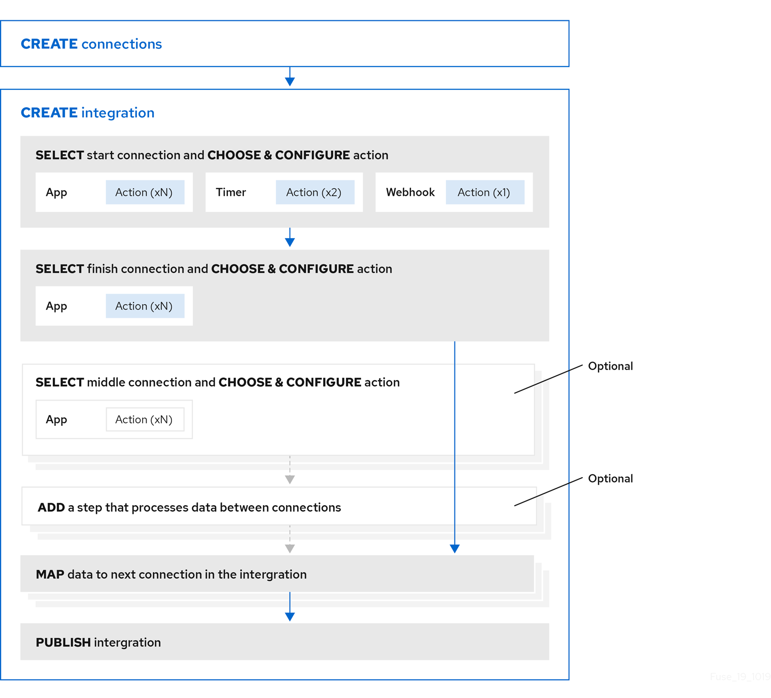
With registration in place for those applications, the workflow for creating a simple integration looks like this:
Additional resource
Benefit, overview, and workflow for creating API provider integrations.
2.3. Example workflow for creating a Salesforce to database simple integration
The best way to understand the workflow for using Fuse Online to create a simple integration is to create the sample integrations by following the instructions in the sample integration tutorials.
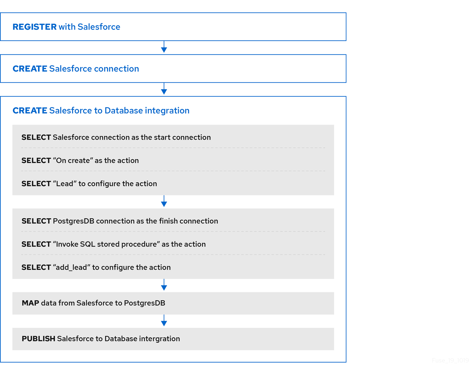
The following diagram shows the workflow for creating the sample Salesforce to Database integration.
After you publish an integration, the Fuse Online dashboard displays Running next to the integration name when the integration is ready to be executed.
Additional resource
Importing and publishing the example API provider quickstart integration.
Chapter 3. About connections to applications that you want to integrate
To connect to applications that you want to integrate, the main steps are:
- Create a connection to each application or service that you want to integrate.
- Create an integration that has a connection to each application that you want to integrate.
The procedure for creating a connection varies for each application or service. The details for creating each kind of connection and configuring it for a particular integration are in Connecting Fuse Online to Applications and Services.
The following topics provide general information about connections:
- Section 3.1, “About creating connections from Fuse Online to applications”
- Section 3.2, “General procedure for obtaining authorization”
- Section 3.3, “About connection validation”
- Section 3.4, “About adding connections to integrations”
- Section 3.5, “How to view and edit connection information”
- Section 3.6, “About creating a connection from a custom connector”
3.1. About creating connections from Fuse Online to applications
To create a connection, you select the connector for the application that you want to connect to and then enter values in input fields to configure a connection to that application. The configuration details that you need to provide vary for each application. After configuring the connection, you give it a name that helps you distinguish it from any other connections to the same application. Optionally, you can specify a description of the connection.
You can use the same connector to create any number of connections to that application. For example, you might use the AMQ connector to create three different connections. Each AMQ connection could specify a different broker.
For examples, see:
3.2. General procedure for obtaining authorization
In an integration, you might want to connect to an application that uses the OAuth protocol to authenticate access requests. To do this, you must register your installation of Fuse Online for access to that application. Registration authorizes all connections from your Fuse Online installation to a given application. For example, if you register your Fuse Online installation with Salesforce, all connections from your Fuse Online installation to Salesforce use the same Salesforce client ID and the same Salesforce client secret that registration provided.
In each Fuse Online environment, for each application that uses OAuth, only one registration of Fuse Online as a client is required. This registration lets you create multiple connections and each connection can use different user credentials.
While the specific steps vary for each OAuth application that you want to connect to, registration always provides your Fuse Online environment with a client ID and a client secret. Some applications use other labels for the client ID and client secret. For example, Salesforce generates a consumer key and a consumer secret.
For some OAuth applications, Fuse Online provides an entry in its Settings page for adding the client ID and client secret that registration provides. To see which applications this applies to, in the left panel of Fuse Online, click Settings.
Prerequisites
- In the Fuse Online Settings page, there is an entry for the application that uses the OAuth protocol to authorize access.
Procedure overview
- In the Fuse Online OAuth Application Management page, expand the entry for the application with which you want to register Fuse Online. This displays the client ID and client secret fields.
-
Near the top of the OAuth Application Management page, where you see
During registration, enter this callback URL:, copy that URL to the clipboard. - In another browser tab, go to the web site for the application that you want to register with and perform the steps that are required to obtain a client ID and secret. One of these steps requires you to enter the callback URL for your Fuse Online environment. Paste the URL that you copied to the clipboard in the second step.
- In Fuse Online, on the Settings page, paste the client ID and client secret and save the settings.
Additional resources
Examples of registering applications that have entries in the Settings page:
- Example of registering with an application that does not have an entry in the Fuse Online Settings page: Registering Fuse Online as a Dropbox client
- Information about using custom connectors that let you access applications that use the OAuth protocol: About creating a connection from a custom connector.
3.3. About connection validation
After obtaining authorization for Fuse Online to access an application that uses OAuth, you can create one or more connections to that application. When you create a connection to an OAuth application, Fuse Online validates it to confirm that authorization is in place. At any time, you can validate the connection again to ensure that authorization is still in place.
Some OAuth applications grant access tokens that have an expiration date. If the access token expires, you can reconnect to the application to obtain a new access token.
To validate a connection that uses OAuth or to obtain a new access token for an OAuth application:
- In the left panel, click Connections.
- Click the connection that you want to validate or for which you want to obtain a new access token.
- In the connection’s details page, click Validate or click Reconnect.
If validation or reconnection fails, then check with the application/service provider to determine if the application’s OAuth keys, IDs, tokens, or secrets are still valid. It is possible that an item has expired or been revoked.
If you find that an OAuth item is invalid, has expired, or been revoked, obtain new values and paste them into the Fuse Online settings for the application. See the instructions in Connecting Fuse Online to Applications and Services for registering the application whose connection did not validate. With the updated settings in place, follow the instructions above to try to validate the updated connection. If validation is successful, and there is a running integration that is using this connection, restart the integration. To restart an integration, stop it and then start it.
If validation fails and reconnection fails but everything appears to be valid at the service provider, then try reregistering your Fuse Online environment with the application and then recreate the connection. Fuse Online validates the connection when you recreate it. If you recreate the connection, and there is an integration that is using the connection, then you must edit the integration to delete the old connection and add the new connection. If the integration is running, then you must stop it and restart it.
3.4. About adding connections to integrations
When you add a connection to a simple integration or to an operation flow, Fuse Online displays a list of the actions that the connection can perform when it connects to the application. You must select exactly one action. In a running integration, each connection performs only the action you choose. For example, when you add a Twitter connection as an integration’s start connection, you might choose the Mention action, which monitors Twitter for tweets that mention your Twitter handle.
Selection of some actions prompts you to specify one or more parameters, which configure the action. For example, if you add a Salesforce connection to an integration and choose the On create action then you must indicate the type of object whose creation you are interested in, such as a lead or a contact.
3.5. How to view and edit connection information
After you create a connection, Fuse Online assigns an internal identifier to the connection. This identifier does not change. You can change the connection’s name, description, or configuration values and Fuse Online recognizes it as the same connection.
There are two ways to view and edit information about a connection:
- In the left panel, click Connections and then click any connection to view its details.
In the left panel, click Integrations and then view any integration to see its summary page. In the integration’s flow diagram:
- For a simple integration, click a connection icon to view that connection’s details.
-
For an API provider integration, click view
 to display the integration’s operation list. Click the operation whose flow contains the connection that you want to view details for.
On the Connection Details page, for the connection that you want to edit, click
 next to a field to edit that field. Or, for some connections, below the configuration fields, click Edit to change configuration values. If you change any values, be sure to click Save.
If you update a connection that is used in an integration that is running, you must republish the integration.
For connections to applications that use the OAuth protocol to authorize access, you cannot change the login credentials that the connection uses. To connect to the application and use different login credentials, you must create a new connection.
3.6. About creating a connection from a custom connector
After you upload an extension that defines a custom connector, the custom connector is available for use. You use custom connectors to create connections in the same way that you use Fuse Online-provided connectors to create connections.
A custom connector might be for an application that uses the OAuth protocol. Before you create a connection from this kind of connector, you must register your Fuse Online environment for access to the application that the connector is for. You do this in the interface for the application that the connector is for. The details for how to register your Fuse Online environment vary for each application.
For example, suppose the custom connector is for creating connections to Yammer. You would need to register your Fuse Online environment by creating a new application within Yammer. Registration provides a Yammer client ID for Fuse Online and a Yammer client secret value for Fuse Online. A connection from your Fuse Online environment to Yammer must provide these two values.
Note that an application might use different names for these values, such as consumer ID or consumer secret.
After you register your Fuse Online environment, you can create a connection to the application. When you configure the connection, there should be parameters for entering the client ID and the client secret. If these parameters are not available, you need to talk with the extension developer and ask for an updated extension that lets you specify the client ID and client secret.
Chapter 4. Creating integrations
After some planning and preparation, you are ready to create an integration. In the Fuse Online web interface, when you click Create Integration, Fuse Online guides you through the procedure to create an integration.
Prerequisites
- Considerations for planning your integrations
According to the kind of integration that you want to create:
- An understanding of the general workflow for creating a simple integration
- An understanding of the general workflow for creating an API provider integration
The following topics provide information and instructions for creating an integration:
- Section 4.1, “Preparation for creating an integration”
- Section 4.2, “Alternatives for triggering integration execution”
- Section 4.3, “General procedure for creating a simple integration”
- Section 4.4, “Adding a timer connection to trigger integration execution”
- Section 4.5, “Integration behavior when the data is in a collection”
- Section 4.6, “About adding steps between connections”
- Section 4.7, “Evaluating integration data to determine the execution flow”
- Section 4.8, “Adding a data mapper step”
- Section 4.9, “Adding a basic filter step”
- Section 4.10, “Adding an advanced filter step”
- Section 4.11, “Adding a template step”
- Section 4.12, “Adding a custom step”
4.1. Preparation for creating an integration
Preparation for creating an integration starts with answers to the questions listed in Considerations for planning your integrations. After you have a plan for the integration, you need to do the following before you can create the integration:
Determine whether an application that you want to connect to uses the OAuth protocol. For each application that uses OAuth, register Fuse Online as a client that is authorized to access that application. Applications that use the OAuth protocol include:
- Dropbox
- Google applications (Gmail, Calendar, Sheets)
- Salesforce
- SAP Concur
- Determine whether an application that you want to connect to uses HTTP basic authentication. For each application that does, identify the user name and password for accessing that application. You need to provide this information when you create the connection.
- For each application that you want to integrate, create a connection.
Additional resources
4.2. Alternatives for triggering integration execution
When you create an integration, the first step in the integration determines how execution of the integration is triggered. The first step in an integration can be one of the following:
Connection to an application or service. You configure the connection for the particular application or service. Examples:
- A connection to Twitter can monitor tweets and trigger execution of a simple integration when a tweet contains text that you specified.
- A connection to Salesforce can trigger execution of a simple integration when anyone creates a new lead.
- A connection to AWS S3 can periodically poll a particular bucket and trigger execution of a simple integration when the bucket contains files.
-
Timer. Fuse Online triggers execution of a simple integration at the interval that you specify. This can be a simple timer or a
cronjob. -
Webhook. A client can send an HTTP
GETorPOSTrequest to an HTTP endpoint that Fuse Online exposes. The request triggers execution of the simple integration. - API Provider. An API provider integration starts with a REST API service. This REST API service is defined by an OpenAPI 3 (or 2) document that you provide when you create an API provider integration. After you publish an API provider integration, Fuse Online deploys the REST API service on OpenShift. Any client with network access to the integration endpoints can trigger execution of the integration.
4.3. General procedure for creating a simple integration
Fuse Online guides you through the procedure for creating a simple integration. It prompts you to choose the start connection, the finish connection, optional middle connections, and other steps. When your integration is complete, you can publish it so that it is running or you can save it for publication at a later time.
To learn about the procedure for creating an API provider integration, see Section 5.3, “Creating an API provider integration”.
Prerequisites
- You have a plan for what the steps in the integration will be.
- You created a connection to each application or service that you want to connect to in this integration.
Procedure
- In the left panel in Fuse Online, click Integrations.
- Click Create Integration.
Choose and configure the start connection:
- On the Choose a connection page, click the connection that you want to use to start the integration. When this integration is running, Fuse Online will connect to this application and obtain data that you want the integration to operate on.
- On the Choose an action page, select the action you want this connection to perform. The available actions vary for each connection.
- On the page for configuring the action, enter values in the fields.
- Optionally, if the connection requires data type specification, Fuse Online prompts you to click Next to specify the input and/or output type of the action.
- Click Next to add the start connection.
As an alternative to connecting to an application, a start connection can be a timer that triggers integration execution at intervals that you specify or it can be a webhook that accepts HTTP requests.
+ After you choose and configure the start connection, Fuse Online prompts you to choose the finish connection.
Choose and configure the finish connection:
- On the Choose a connection page, click the connection you want to use to complete the integration. When this integration is running, Fuse Online will connect to this application with the data that the integration has been operating on.
- On the Choose an action page, select the action you want this connection to perform. The available actions vary for each connection.
- On the page for configuring the action, enter values in the fields.
- Optionally, if the connection requires data type specification, Fuse Online prompts you to click Next to specify the input and/or output type of the action.
- Click Next to add the finish connection.
As an alternative to connecting to an application, a finish connection can send information to the integration’s log about the messages that the integration processed. To do this, select Log when Fuse Online prompts you to choose the finish connection.
- Optionally, add one or more connections between the start connection and the finish connection. For each connection, choose its action and enter any required configuration details.
- Optionally, add one or more steps that operate on integration data between connections. See About adding steps between connections.
-
In the integration visualization, look for any
 icons. These warnings indicate that a data mapper step is needed before this connection. Add the required data mapper steps.
- When the integration contains all needed steps, click Save or Publish according to whether you want to start running the integration.
- In the Name field, enter a name that distinguishes this integration from any other integrations.
- Optionally, in the Description field, enter a description, for example, you can indicate what this integration does.
Optionally, from the list of library extensions that you have imported, you can select one or more library extensions to associate with the integration. Note that you must have already imported a library
.jarfile as a Fuse Online extension if you want it to appear in this list so that you can select it.For more information about library extensions, see How to develop library extensions.
If you are ready to start running the integration, click Save and publish.
Fuse Online displays the integration summary. You can see that Fuse Online is in the process of publishing it. It may take a few moments for the status of the integration to become Running.
If you do not want to publish the integration, click Save. Fuse Online saves the integration and displays its flow visualization. You can continue editing it. Or, in the breadcrumbs at the top of the page, click Integrations to display the list of integrations. If you saved but did not publish the integration, then Stopped appears on the integration’s entry.
4.4. Adding a timer connection to trigger integration execution
To trigger execution of an integration according to a schedule that you specify, add a timer connection as a simple integration’s start connection. A timer connection cannot be in the middle of a flow nor at the end of a flow.
Procedure
- In Fuse Online, on the left, click Integrations.
- Click Create Integration.
On the Choose a connection page, click Timer.
Fuse Online provides a Timer connection; you do not need to create a timer connection.
On the Choose an action page, select Cron or Simple.
-
A
crontimer requires acronexpression that specifies the schedule for triggering integration execution. -
A simple timer prompts you to specify a period and its time unit, for example,
5 seconds,1 hour. Available units are milliseconds, seconds, minutes, hours, days.
-
A
-
According the type of timer that you are adding, enter a
cronexpression or a period with a selected time unit. - Click Next to add the Timer connection as the integration’s start connection.
4.5. Integration behavior when the data is in a collection
Sometimes, a connection returns a collection, which contains multiple values that are all the same type. When a connection returns a collection, the flow can operate on the collection in a number of ways, including:
- Execute each step once for the collection.
- Execute each step once for each element in the collection.
- Execute some steps once for the collection and execute other steps once for each element in the collection.
To decide how to operate on a collection in a flow, you need to know which applications the flow connects to, whether they can handle collections, and what you want the flow to accomplish. You can then use the information in the following topics to add steps to a flow that processes a collection:
- Section 4.5.1, “About data types and collections in the data mapper”
- Section 4.5.2, “About processing collections”
- Section 4.5.3, “Using the data mapper to process collections”
- Section 4.5.4, “Adding a split step”
- Section 4.5.5, “Adding an aggregate step”
- Section 4.5.6, “Example of processing a collection in a flow”
4.5.1. About data types and collections in the data mapper
In the data mapper, a field can be:
-
A primitive type that stores a single value. Examples of primitive types include
boolean,char,byte,short,int,long,float, anddouble. A primitive type is not expandable because it is a single field. - A complex type that consists of multiple fields of different types. You define the child fields of a complex type at design time. In the data mapper, a complex type is expandable so that you can view its child fields.
Each type of field (primitive and complex) can also be a collection. A collection is a single field that can have multiple values. The number of items in a collection is determined at runtime. At design time, in the data mapper, a collection is indicated by
![]() . Whether a collection is expandable in the data mapper interface is determined by its type. When a collection is a primitive type, it is not expandable. When a collection is a complex type, then the data mapper is expandable to display the collection’s child fields. You can map from/to each field.
. Whether a collection is expandable in the data mapper interface is determined by its type. When a collection is a primitive type, it is not expandable. When a collection is a complex type, then the data mapper is expandable to display the collection’s child fields. You can map from/to each field.
Here are some examples:
-
IDis a primitive type field (int). At runtime, an employee can have only oneID. For example,ID=823. Therefore,IDis a primitive type that is not also a collection. In the data mapper,IDis not expandable. -
emailis a primitive type field (string). At runtime, an employee can have multipleemailvalues. For example,email<0>=aslan@home.comandemail<1>=aslan@business.com. Therefore,emailis a primitive type that also is a collection. The data mapper uses to indicate that the
 emailfield is a collection butemailis not expandable because it is a primitive type (it does not have child fields). -
employeeis a complex object field that has several child fields, includingIDandemail. At runtime,employeeis also a collection, because the company has many employees.
At design time, the data mapper uses
to indicate that employeeis a collection. Theemployeefield is expandable because it is a complex type that has child fields.
4.5.2. About processing collections
The easiest way for a flow to process a collection is to use the data mapper to map fields that are in a source collection to fields that are in a target collection. For many flows, this is all that is required. For example, a flow might obtain a collection of employee records from a database and then insert those records into a spreadsheet. Between the database connection and the Google Sheets connection, a data mapper step maps the database fields to the Google Sheets fields. Since both the source and the target are collections, when Fuse Online executes the flow, it calls the Google Sheets connection once. In that call, Fuse Online iterates through the records and correctly populates the spreadsheet.
In some flows, you might need to split a collection into individual objects. For example, consider a flow that connects to a database and obtains a collection of employees who will lose allotted time off if they do not use it before a certain date. The flow then needs to send an email notification to each of these employees. In this flow, you would add a split step after the database connection. You would then add a data mapper step that maps the source fields for an employee record to target fields in a Gmail connection that sends a message. When Fuse Online executes the flow, it executes the data mapper step and the Gmail connection once for each employee.
Sometimes, after you split a collection in a flow, and after the flow executes some steps once for each element that was in the collection, you want the flow to operate on the collection again. Consider the example in the previous paragraph. Suppose that after a Gmail connection sends a message to each employee, you want to add a list of the employees who were notified to a spreadsheet. In this scenario, after the Gmail connection, add an aggregate step to create a collection of employee names. Then add a data mapper step that maps fields in the source collection to fields in the target Google Sheets connection. When Fuse Online executes the flow, it executes the new data mapper step and the Google Sheets connection once for the collection.
These are the most common scenarios for processing a collection in a flow. However, much more complex processing is also possible. For example, when the elements in a collection are themselves collections, you can nest split and aggregate steps inside other split and aggregate steps.
4.5.3. Using the data mapper to process collections
In a flow, when a step outputs a collection and when a subsequent connection that is in the flow expects a collection as the input, you can use the data mapper to specify how you want the flow to process the collection.
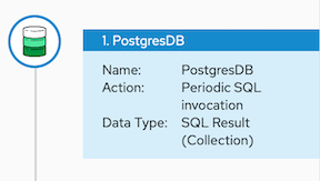
When a step outputs a collection, the flow visualization displays Collection in the details about the step. For example:
Add a data mapper step after the step that provides the collection and before the step that needs the mappings. Exactly where in the flow this data mapper step needs to be depends on the other steps in the flow. The following image shows mappings from source collection fields to target collection fields:

In the source and target panels, the data mapper displays
![]() to indicate a collection.
to indicate a collection.
When a collection is a complex type, the data mapper displays the collection’s child fields. You can map from/to each field.
When a source field is nested in a number of collections you can map it to a target field that meets one of these conditions:
The target field is nested in the same number of collections as the source field. For example, these mappings are allowed:
- /A<>/B<>/C → /D<>/E<>/F
- /A<>/B<>/C → /G<>/H/I<>/J
The target field is nested in only one collection. For example, this mapping is allowed:
/A<>/B<>/C → /K<>/L
In this case, the data mapper uses a depth-first algorithm to iterate over all values in the source. In order of occurrence, the data mapper puts the source values into a single target collection.
The following mapping is not allowed:
/A<>/B<>/C cannot-map-to /M<>/N/O<>/P<>/Q
When Fuse Online executes the flow, it iterates over the source collection elements to populate the target collection elements. If you map one or more source collection fields to a target collection or to target collection fields, the target collection elements contain values for only the mapped fields.
If you map a source collection or a field in a source collection to a target field that is not in a collection, then when Fuse Online executes the flow, it assigns the value from only the last element in the source collection. Any other elements in the collection are ignored in that mapping step. However, any subsequent mapping steps can access all elements in the source collection.
When a connection returns a collection that is defined in a JSON or Java document, the data mapper can usually process the source document as a collection.
4.5.4. Adding a split step
During execution of a flow, when a connection returns a collection of objects, Fuse Online executes subsequent steps once for the collection. If you want to execute subsequent steps once for each object that is in the collection, add a split step. For example, a Google Sheets connection returns a collection of row objects. To execute subsequent steps once for each row, add a split step after the Google Sheets connection.
Ensure that the input to a split step is always a collection. If a split step gets a source document that is not a collection type, the step splits the input at each space. For example, Fuse Online splits “Hello world!” input into two elements: “Hello” and “world!”, and passes those two elements to the next step in the flow. In particular, XML data is not a collection type.
Prerequisites
- You are creating or editing a flow.
- The flow already has all the connections that it requires.
- In the flow visualization, the connection that obtains the source data indicates that the data is a (Collection).
Procedure
-
In the flow visualization, click the
 at the location where you want to add the split step.
- Click Split. This step does not require any configuration.
- Click Next.
Additional information
Typically, you want to add any split steps and aggregate steps before you add data mapper steps. This is because whether the data is a collection or individual objects affects the mappings. If you add a data mapper step and then add a split step, you usually need to redo the mappings. Likewise, if you remove a split or aggregate step, then you would need to redo any mappings.
4.5.5. Adding an aggregate step
In a flow, add an aggregate step where you want Fuse Online to create a collection from individual objects. During execution, after an aggregate step, instead of executing subsequent steps once for each object, Fuse Online executes subsequent steps once for the collection.
When deciding whether to add an aggregate step to a flow, consider the connections in the flow. After a split step, for each subsequent connection, Fuse Online connects to that application once for each element in the flow’s data. For some connections, it might be preferable to connect once rather than multiple times.
Prerequisites
- You are creating or editing a flow.
- The flow already has all the connections that it requires.
- A previous step split a collection into individual objects.
Procedure
-
In the flow visualization, where you want to add an aggregate step to the flow, click the
.
- Click Aggregate. This step does not require any configuration.
- Click Next.
Additional information
Typically, you want to add any split and aggregate steps before you add data mapper steps. This is because whether the data is a collection or individual objects affects the mappings. If you add a data mapper step and then add an aggregate step, you usually need to redo the mappings. Likewise, if you remove an aggregate step, then you would need to redo any mappings.
4.5.6. Example of processing a collection in a flow
This simple integration obtains a collection of tasks from the sample database provided with Fuse Online. The flow splits the collection into individual task objects and then filters these objects to find the tasks that have been done. The flow then aggregates the completed tasks in a collection, maps the fields in that collection to fields in a spreadsheet, and finishes by adding a list of completed tasks to a spreadsheet.
The procedure below provides instructions for creating this simple integration.
Prerequisites
- You created a Google Sheets connection.
- In the account that the Google Sheets connection accesses, there is a spreadsheet for receiving the database records.
Procedure
- Click Create Integration.
Add the start connection:
- On the Choose a connection page, click PostgresDB.
- On the Choose an action page, select Periodic SQL Invocation.
-
In the SQL Statement field, enter
select * from todoand click Next.
This connection returns a collection of task objects.
Add the finish connection:
- On the Choose a connection page, click your Google Sheets connection.
- On the Choose an action page, select Append values to a sheet.
- In the SpreadsheetId field, enter the ID of the spreadsheet to add the list of tasks to.
-
In the Range field, enter
A:Bas the target columns that you want to append values to. The first column, A, is for the task IDs. The second column, B, is for the task names. - Accept the defaults for Major Dimension and for Value Input Option, and click Next.
The Google Sheets connection finishes the flow by adding each element in a collection to a spreadsheet.
Add a split step to the flow:
- In the flow visualization, click the plus sign.
- Click Split.
After the flow executes the split step, the result is a set of individual task objects. Fuse Online executes the subsequent steps in the flow once for each individual task object.
Add a filter step to the flow:
- In the flow visualization, after the split step, click the plus sign.
Click Basic Filter and configure the filter as follows:
-
Click in the first field and select
completed, which is the name of the field that contains the data that you want to evaluate. - In the second field, select equals as the condition that the completed field value must satisfy.
-
In the third field, specify
1as the value that must be in the completed field.1indicates that the task has been completed.
-
Click in the first field and select
- Click Next.
During execution, the flow executes the filter step once for each task object. The result is a set of individual, completed task objects.
Add an aggregate step to the flow:
- In the flow visualization, after the filter step, click the plus sign.
- Click Aggregate.
Now the result set contains one collection, which contains an element for each completed task.
Add a data mapper step to the flow:
- In the flow visualization, after the aggregate step, click the plus sign.
Click Data Mapper and map the following fields from the SQL result source collection to the Google Sheets target collection:
- id to A
- task to B
- Click Done.
- Click Publish.
Results
When the integration is running, it obtains tasks from the sample database every minute and then adds the completed tasks to the first sheet in the spreadsheet. The integration maps the task ID to the first column, A, and it maps the task name to the second column, B.
4.6. About adding steps between connections
Although it is not a requirement, the recommendation is to add all needed connections to a primary flow and then, according to the processing that you want the flow to execute, add additional steps between connections. In a flow, each step operates on data obtained from the previous connection(s) and any previous steps. The resulting data is available to the next step in the flow.
Often, you must map data fields that are received from a connection to data fields that the next connection in the flow can operate on. After you add all connections to a flow, check the flow visualization. For each connection that requires data mapping before it can operate on the input data, Fuse Online displays
 . Click this icon to see Data Type Mismatch: Add a data mapper step before this connection to resolve the difference.
You can click the link in the message to display the Configure Mapper page in which you add and specify a data mapper step. However, the recommendation is to add other needed steps, and then add data mapper steps last.
4.7. Evaluating integration data to determine the execution flow
In a flow, a Conditional Flows step evaluates integration data against conditions that you specify. For each specified condition, you add connections and other steps to the flow associated with that condition. During execution, a Conditional Flows step evaluates incoming data to determine which flow to execute.
The following topics provide details:
- Section 4.7.1, “Behavior of a Conditional Flows step”
- Section 4.7.2, “Example of a Conditional Flows step”
- Section 4.7.3, “General procedure for configuring a Conditional Flows step”
- Section 4.7.4, “Using the basic expression builder to specify conditions”
- Section 4.7.5, “Using the advanced expression builder to specify conditions”
- Section 4.7.6, “Adding steps to conditional flows”
4.7.1. Behavior of a Conditional Flows step
During integration development, you can add a Conditional Flows step to a flow and define one or more conditions. For each condition, you add steps to a conditional flow that is associated with only that condition. During integration execution, for each message that the previous integration step passes to a Conditional Flows step, the Conditional Flows step evaluates the message content against the specified conditions in the order in which you define them in the Fuse Online page for specifying conditions.
In a Conditional Flows step, the behavior is one of the following:
- For the first condition that evaluates to true, the integration executes the conditional flow that is associated with that condition.
- If no conditions evaluate to true, and there is a default conditional flow, the integration executes that flow.
- If no conditions evaluate to true and there is no default conditional flow, the integration does not execute a conditional flow.
After executing a conditional flow, or after no conditions evaluate to true and there is no default conditional flow, the integration executes the next step in the primary flow.
4.7.2. Example of a Conditional Flows step
Suppose that an integration connects to a SQL database to obtain information about how much paid-time-off (PTO) each employee has. The returned data indicates:
- Some employees might lose PTO if they do not use it by a certain date.
- Other employees already used more PTO than they earned.
- The rest of the employees have PTO that they can use without time restrictions.
In a Conditional Flows step, this example integration can define two conditions, an execution flow for each condition, and a default execution flow:
- When PTO is greater than some number, it indicates that some PTO might be lost if not used by a certain date. When this condition evaluates to true, the integration executes a flow that sends email to affected employees. The email contains the amount of PTO that must be used and the date by which it must be used.
- When PTO is a negative number, it indicates that some PTO has been used but not earned. When this condition evaluates to true, the integration executes a flow that sends an email to affected employees. The email contains the amount of PTO that the employee has overdrawn and specifies the date on which the employee begins to accrue PTO again.
- When neither of the two conditions evaluates to true, the integration executes the default flow. This example integration executes the default conditional flow for employees whose PTO is neither a negative number nor above some specified number. The default flow sends an email to those employees with a statement of the amount of PTO that the employee has.
4.7.3. General procedure for configuring a Conditional Flows step
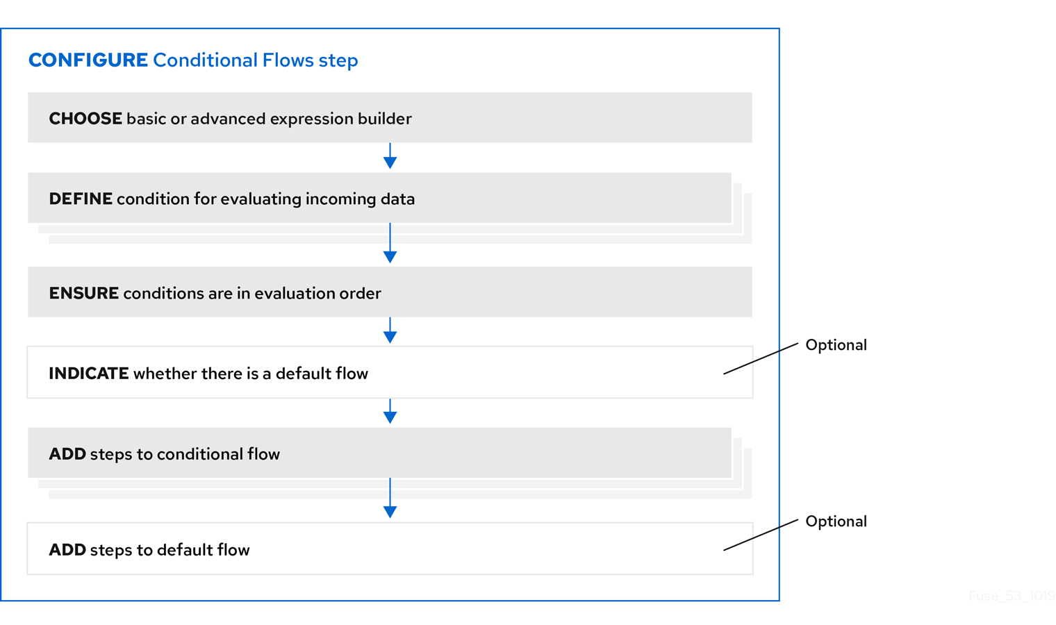
After you add a Conditional Flows step to a flow, the workflow for configuring the step is as shown in the following image:
More about the workflow
- The basic expression builder prompts you for the property that contains the content that you want to evaluate, and the condition and value that you want to test for. The basic expression builder is suitable for most Conditional Flows steps.
- The advanced expression builder lets you specify a conditional expression in Camel Simple Language.
- You must use the same expression builder for all conditions. In other words, to configure a Conditional Flows step, you must use the basic expression builder or the advanced expression builder. You cannot use both.
- In a conditional flow, you cannot add a Conditional Flows step.
4.7.4. Using the basic expression builder to specify conditions
In a flow, add a Conditional Flows step when you want to evaluate incoming data to determine the integration’s execution path. The procedure described here shows how to use the basic expression builder to specify conditions.
Prerequisites
- You are creating or editing a primary flow. If this is a simple integration, the start and finish connections have been added.
- Input to a Conditional Flows step must be an individual message. In the integration visualization, if the previous step’s Data Type shows (Collection), add a Split step after the previous step and before this Conditional Flows step.
- You are familiar with the fields that will be in the messages that the integration passes to the Conditional Flows step you are about to add.
Procedure
-
In the integration visualization, where you want to add a Conditional Flows step, click
.
- Click Conditional Flows.
- Click Select in the Basic expression builder entry.
In the Configure Conditional Flows page, define one or more conditions:
- Click in the initial When field.
- In the list of properties, click the property that contains the content that you want the Conditional Flows step to evaluate.
- In the next field, accept Contains as the condition for which the step evaluates the data or select another condition. The condition that you select in this field must evaluate to true for the value that you enter in the next field.
- In the third field, specify the value that the condition tests for.
- Optional. Click Add another condition to specify another condition.
- Repeat this set of steps for each additional condition that you want to define.
- Optional. Change the order in which the integration evaluates the defined conditions by clicking the up or down arrow to the right of a condition.
Optional. Click Execute default flow if you want there to be a default conditional flow.
If you select Execute default flow, during execution, if none of the conditions that you specified evaluates to true, the integration executes the default conditional flow. If you do not select Execute default flow, during execution, if none of the conditions that you specified evaluates to true, the integration continues execution with the step that follows this Conditional Flows step.
- Click Next.
- Optional. Specify the output data type if Fuse Online prompts for it. All conditional flows that are part of this Conditional Flows step must have the same output type.
Click Next.
Fuse Online displays the flow visualization. Below the Conditional Flows step that you are adding, there is an entry for each condition that you specified, as well as an entry for an Otherwise default flow if you indicated that the Conditional Flows step has a default flow.
Next step
For each condition, add steps to its associated flow. If there is a default flow, add steps to the default flow.
Additional resources
- For details about the conditions that you can select in the middle field for each condition, see Camel Simple Language operators. Note that the matches condition corresponds to the Simple Language regex operator.
- If you cannot define the conditions that you need by using the basic expression builder, see Using the advanced expression builder to specify conditions.
4.7.5. Using the advanced expression builder to specify conditions
In a flow, add a Conditional Flows step when you want to evaluate incoming data to determine the integration’s execution path. The procedure described here shows how to use the advanced expression builder to specify conditional expressions in Camel Simple Language.
Prerequisites
- You are creating or editing a primary flow. If this is a simple integration, the start and finish connections have been added.
- Input to a Conditional Flows step must be an individual message. In the integration visualization, if the previous step’s Data Type shows (Collection), add a Split step.
- You are familiar with the fields that will be in the messages that the integration passes to the Conditional Flows step you are about to add.
- You are familiar with the Camel Simple Expression language or you have expressions for the conditions that you want to evaluate.
Procedure
-
In the integration visualization, where you want to add a Conditional Flows step, click
.
- Click Conditional Flows.
- Click Select in the Advanced expression builder entry.
In the Configure Conditional Flows page, define one or more conditions:
In the initial When field, enter a Camel Simple Language conditional expression. For example, the following expression evaluates to true when the body of the message contains a
ptofield that is greater than160:${body.pto} > 160When this expression evaluates to true, the integration executes the conditional flow that you create and associate with this condition.
NoteIn an expression, an additional property specification is required when the Conditional Flows step is in one of the following kinds of flows:
- An API provider integration operation flow
- A simple integration that starts with a webhook connection
- A simple integration that starts with a custom REST API connection
In these flows, Fuse Online wraps the actual message content inside a
bodyproperty. This means that the input to a Conditional Flows step contains abodyproperty that contains anotherbodyproperty that contains the actual message content. Consequently, in an expression that is in a Conditional Flows step that is in one of these kinds of flows, you must specify two instances ofbody. For example, suppose you want to evaluate content that is in theptofield of the input message. Specify the expression like this:${body.body.pto} > 160- Optional. Click Add another condition, and repeat the previous step. Do this for each additional condition that you want to define.
- Optional. Change the order in which the Conditional Flows step evaluates the defined conditions by clicking the up or down arrow to the right of a condition field.
Optional. Click Execute default flow if you want there to be a default conditional flow.
If you select Execute default flow, during execution, if none of the conditions that you specified evaluates to true, the integration executes the default conditional flow. If you do not select Execute default flow, during execution, if none of the conditions that you specified evaluates to true, the integration continues execution with the step that follows this Conditional Flows step.
- Click Next.
- Optional. Specify the output data type if Fuse Online prompts for it. All conditional flows that are part of this Conditional Flows step must have the same output type.
Click Next.
Fuse Online displays the flow visualization. Below the Conditional Flows step that you are adding, there is an entry for each condition that you specified, as well as an entry for an Otherwise default flow if you indicated that the Conditional Flows step has a default flow.
Next step
For each condition, add steps to its associated flow. If there is a default flow, add steps to the default flow.
Additional resources
4.7.6. Adding steps to conditional flows
In a Conditional Flows step, after you define conditions, for each condition, add steps to the flow that is associated with that condition. During execution, when the Conditional Flows step evaluates a condition as true, it executes the flow that is associated with that condition.
Prerequisites
- You defined the conditions for this Conditional Flows step.
- You are familiar with the fields that will be in the messages that the integration passes to this Conditional Flows step.
- You created each connection that you want to add to a conditional flow.
Procedure
In the integration visualization, for the condition whose flow you want to add to, click Open Flow.
Fuse Online displays that condition near the top of the page. The conditional flow visualization shows the Flow Start and Flow End steps that all conditional flows have.
-
In the flow visualization, click
where you want to add a step to this conditional flow.
Click the step that you want to add. You can add any connection or step that you can add to a primary flow.
The output from the Flow Start step is always the same as the output from the primary flow step that is before this Conditional Flows step. For example, if you add a filter step or a data mapper step to this conditional flow, the available fields are the same fields that would be available in the primary flow.
- Configure the step as needed.
- Repeat the previous three instructions for each step that you want to add to this conditional flow.
- At the top of the page, in the Flow field, click the down carat and click Back to primary flow, which saves this conditional flow and displays the primary flow.
- For each conditional flow that you want to add to, repeat this procedure.
Results
The primary flow has a conditional flow for each condition that you defined in the Conditional Flows step. If you selected the Execute default flow option, the primary flow also has a default conditional flow.
During execution, the Conditional Flows step executes the conditional flow that is associated with the first condition that evaluates to true. The integration then executes the step that follows the Conditional Flows step.
If no condition evaluates to true then the Conditional Flows step executes the default conditional flow. The integration then executes the step that follows the Conditional Flows step.
If both of the following are true:
- No condition evaluates to true.
- There is no default conditional flow.
Then the integration executes the step that follows the Conditional Flows step.
4.8. Adding a data mapper step
Almost all integrations require data mapping. A data mapper step maps data fields from the previous connection(s) and any other steps to data fields that the next connection in the flow can operate on. For example, suppose the integration data contains a Name field and the next connection in the flow has a CustomerName field. You need to map the source Name field to the target CustomerName field.
The data mapper displays the largest possible set of source fields that can be provided by the previous integration step. However, not all connections provide data in each displayed source field. For example, a change to a third-party application might discontinue providing data in a particular field. As you create an integration, if you notice that data mapping is not behaving as you expect, ensure that the source field that you want to map contains the data that you expect.
Prerequisite
You are creating or editing a flow.
Procedure
-
In the flow visualization, where you want to add a data mapper step, click the
.
- Click Data Mapper to display source and target fields in the data mapper canvas.
Next step
See Mapping integration data to fields for the next connection.
4.9. Adding a basic filter step
You can add a step to a flow to filter the data that the flow operates on. In a filter step, Fuse Online inspects the data and continues only if the content meets criteria that you define. For example, in a flow that obtains data from Twitter, you can specify that you want to continue execution by operating only on tweets that contain "Red Hat".
Prerequisites
- The flow contains all connections that it needs to.
- You are creating or editing a flow.
Procedure
-
In the flow visualization, where you want to add a filter step, click the
.
- Click Basic Filter.
On the Configure Basic Filter Step page, in the Continue only if incoming data match field:
- Accept the default that all defined rules must be satisfied.
- Or, select ANY of the following to indicate that only one rule must be satisfied.
Define the filter rule:
In the Property Name field, enter or select the name of the field that contains the content you want the filter to evaluate. For example, suppose the data coming in to the step consists of tweets that mention your Twitter handle. You want to continue execution only when the tweet contains certain content. The tweet is in a field named
textso you enter or selecttextas the value in the property name field.You can define the property name in the following ways:
- Start typing. The field has a typeahead feature that provides a list of possible completions for you in a pop-up box. Select the correct one from the box.
- Click in the field. A dropdown box appears with a list of available properties. Select the property of interest from the list.
- In the Operator field, select an operator from the dropdown box. The setting defaults to Contains. For execution to continue, the condition that you select in this field must evaluate to true for the value that you enter in the Keywords field.
- In the Keywords field, enter a value to filter on. For example, suppose that you accept the default Contains operator and you want to continue integration execution only when the incoming text mentions a certain product. You would enter the product name here.
Optionally, click + Add another rule and define another rule.
You can delete a rule by clicking the trash can icon in the top right of the rule entry.
- When the filter step is complete, click Done to add it to the flow.
Additional resources
- For details about the operators and for examples of specifying text to evaluate, see Camel Simple Language operators. Note that the basic filter step matches operator corresponds to the Simple Language regex operator.
- If you cannot define the filter you need in a basic filter step, see Adding an advanced filter step.
4.10. Adding an advanced filter step
In a filter step, Fuse Online inspects the data and continues executing the flow only if the content meets criteria that you define. If the basic filter step does not let you define the exact filter that you need, then add an advanced filter step.
Prerequisites
- The flow contains all connections that it needs to.
- You are creating or editing a flow.
- You are familiar with the Camel Simple Language, or you have been provided with a filter expression.
Procedure
-
In the flow visualization, where you want to add an advanced filter step to the flow, click the
.
- Click Advanced Filter.
In the edit box, use the Camel Simple Language to specify a filter expression. For example, the following expression evaluates to true when the message header’s
typefield is set towidget:${in.header.type} == 'widget'In the following example, the expression evaluates to true when the body of the message contains a
titlefield:${in.body.title}- Click Next to add the advanced filter step to the flow.
Additional property specification in some kinds of flows
In an expression, an additional property specification is required when the advanced filter step is in one of the following kinds of flows:
- An API provider integration operation flow
- A simple integration that starts with a webhook connection
- A simple integration that starts with a custom REST API connection
In these flows, Fuse Online wraps the actual message content inside a body property. This means that the input to the advanced filter contains a body property that contains another body property that contains the actual message content. Consequently, in an advanced filter expression that is in one of these kinds of flows, you must specify two instances of body. For example, suppose you want to evaluate content that is in the completed field of the input message. Specify the expression like this:
${body.body.completed} = 14.11. Adding a template step
In a flow, a template step takes data from a source and inserts it into the format that is defined in a template that you upload to Fuse Online. The benefit of a template step is that it provides data output in a consistent format that you specify.
In the template, you define placeholders and specify static text. When you create the flow, you add a template step, map source fields to the template placeholders, and then map template content to the next step in the flow. When Fuse Online executes the flow, it inserts the values that are in the mapped source fields into an instance of the template and makes the result available to the next step in the flow.
If a flow includes a template step then it is most likely the only template step in that flow. However, more than one template step in a flow is allowed.
Fuse Online supports the following kinds of templates: Freemarker, Mustache, Velocity.
Prerequisites
- You must be creating or editing a flow.
- If you are creating a simple integration then it must already have its start and finish connections.
Procedure
-
In the flow visualization, click the
where you want to add a template step.
- Click Template. The Upload Template page opens.
- Specify the template type, which is Freemarker, Mustache, or Velocity.
To define the template, do one of the following:
- Drag and drop a template file or a file that contains text that you want to modify to create a template, into the template editor.
- Click browse to upload, navigate to a file, and upload it.
- In the template editor, start typing to define a template.
-
In the template editor, ensure that the template is valid for use with Fuse Online. Examples of valid templates are after this procedure. Fuse Online displays
 to the left of a line that contains a syntax error. Hovering over a syntax error indicator displays hints about how to resolve the error.
Click Done to add the template step to the flow.
If the Done button is not enabled then there is at least one syntax error that you must correct.
Input to a template step must be in the form of a JSON object. Consequently, you must add a data mapping step before a template step.
To add a data mapper step before the template step:
-
In the flow visualization, click the
that is immediately before the template step that you just added.
- Click Data Mapper.
In the data mapper, map a source field to each template placeholder field.
For example, using the example templates that are after this procedure, map a source field to each of these template fields:
-
time -
name -
text
-
- In the upper right, click Done to add the data mapper step to the flow.
Output from a template step is always a JSON object. Consequently, you must add a data mapper step after a template step.
-
In the flow visualization, click the
To add a data mapper step after the template step:
-
In the flow visualization, click the
that is immediately after the template step that you just added.
- Click Data Mapper.
- In the data mapper, map the template’s message field, which always contains the result of inserting source fields into the template, to a target field. For example, suppose that a Gmail connection is next in the flow and you want to send the result of the template step as the content of a Gmail message. To do this, you would map the message source field to the text target field.
- In the upper right, click Done.
-
In the flow visualization, click the
Examples of templates
Example of a Mustache template:
At {{time}}, {{name}} tweeted:
{{text}}
Freemarker and Velocity support this example template:
At ${time}, ${name} tweeted:
${text}
Velocity also supports syntax without braces, as shown in this example:
At $time, $name tweeted:
$text
A placeholder cannot contain a . (period).
Additional resources
For details about mapping fields, see Mapping integration data to fields for the next connection.
4.12. Adding a custom step
If Fuse Online does not provide a step that you need in a flow, a developer can define one or more custom steps in an extension. A custom step operates on data between connections in a flow.
You add a custom step to a flow in the same way that you add a built-in step. For a simple integration, choose the start and finish connections, add other connections as needed and then add additional steps. For an API provider integration, select the operation whose flow executes the custom step, add connections as needed to the flow, and then add other steps. When you add a step, Fuse Online operates on the data it receives from the previous step(s) in the flow.
Prerequisites
- You uploaded the custom step extension to Fuse Online. See Making custom features available.
- You are creating or editing a flow.
- The flow already has all the connections that it requires.
Procedure
-
In the flow visualization, where you want to add a custom step, click the
.
Click the custom step that you want to add.
The available steps includes any custom steps that are defined in extensions that were uploaded to your Fuse Online environment.
- Respond to prompts for any information that is required to perform the step. This information varies for each custom step.
Chapter 5. Creating an integration that is triggered by a REST API call
To trigger execution of an integration on demand, start the integration with a REST API description document that you provide. Integrations that start this way are referred to as API provider integrations. An API provider integration allows REST API clients to invoke commands that trigger execution of the integration.
When Fuse Online publishes an API provider integration, any client with network access to the integration endpoints can trigger execution of the integration.
If you are using Fuse Online on OpenShift Container Platform on-site, an administrator can configure the Fuse Online server to enable Red Hat 3scale discovery of API provider integration APIs. By default, Fuse Online annotates an API provider integration’s API service definition for use with 3scale but does not expose those APIs for automatic 3scale discovery. Without 3scale discovery, there is no access control. With 3scale discovery, you can set access policies, centralize control, and provide high availability for your API provider integration APIs. For more information, see the API Gateway documentation that is available from the Red Hat 3scale documentation page.
See also: Configuring Fuse Online to enable 3scale discovery of APIs.
The following topics provide information and instructions for creating API provider integrations:
- Section 5.1, “Benefit, overview, and workflow for creating API provider integrations”
- Section 5.2, “How OpenAPI operations relate to API provider integration flows”
- Section 5.3, “Creating an API provider integration”
- Section 5.4, “Defining the operation flows for an API provider integration”
- Section 5.5, “Importing and publishing the example API provider quickstart integration”
- Section 5.6, “Testing the example API provider quickstart integration”
For a video that shows how to create, publish and test an API provider integration, see https://youtu.be/sox8SSqJ0zQ.
5.1. Benefit, overview, and workflow for creating API provider integrations
An API provider integration starts with a REST API service. This REST API service is defined by an OpenAPI 3 (or 2) document that you provide when you create an API provider integration. After you publish an API provider integration, Fuse Online deploys the REST API service on OpenShift. The benefit of an API provider integration is that REST API clients can invoke calls that trigger execution of the integration.
Multiple execution flows
An API provider integration has multiple execution paths, referred to as flows. Each operation that the OpenAPI document defines has its own flow. In Fuse Online, for each operation that the OpenAPI document defines, you add connections and other steps to the execution flow for that operation. These steps process the data as required for the particular operation.
Example execution flow
For example, consider a human resources application that calls a REST API service that Fuse Online has made available. Suppose the call invokes the operation that adds a new employee. The operation flow that handles this call could:
- Connect to an application that creates an expense report for new employee equipment.
- Connect to a SQL database to add an internal ticket for setting up new equipment.
- Connect to Google mail to send a message to the new employee that provides orientation information.
Ways to trigger execution
There are many ways to call the REST APIs that trigger integration execution, including:
- A web browser page that takes data input and generates the call.
-
An application that explicitly calls the REST APIs, such as the
curlutility. - Other APIs that call the REST API, for example, a webhook.
Ways to edit a flow
For each operation, you can edit its flow by:
- Adding connections to the applications that need to process the data.
- Adding steps between connections, including split, aggregate, and data mapping steps.
- Mapping connection error messages to return codes in the HTTP response that finishes the flow. The response goes to the application that invoked the call that triggered execution of the integration.
Workflow for creating an API provider integration
The general workflow for creating an API provider integration is shown in the following diagram:
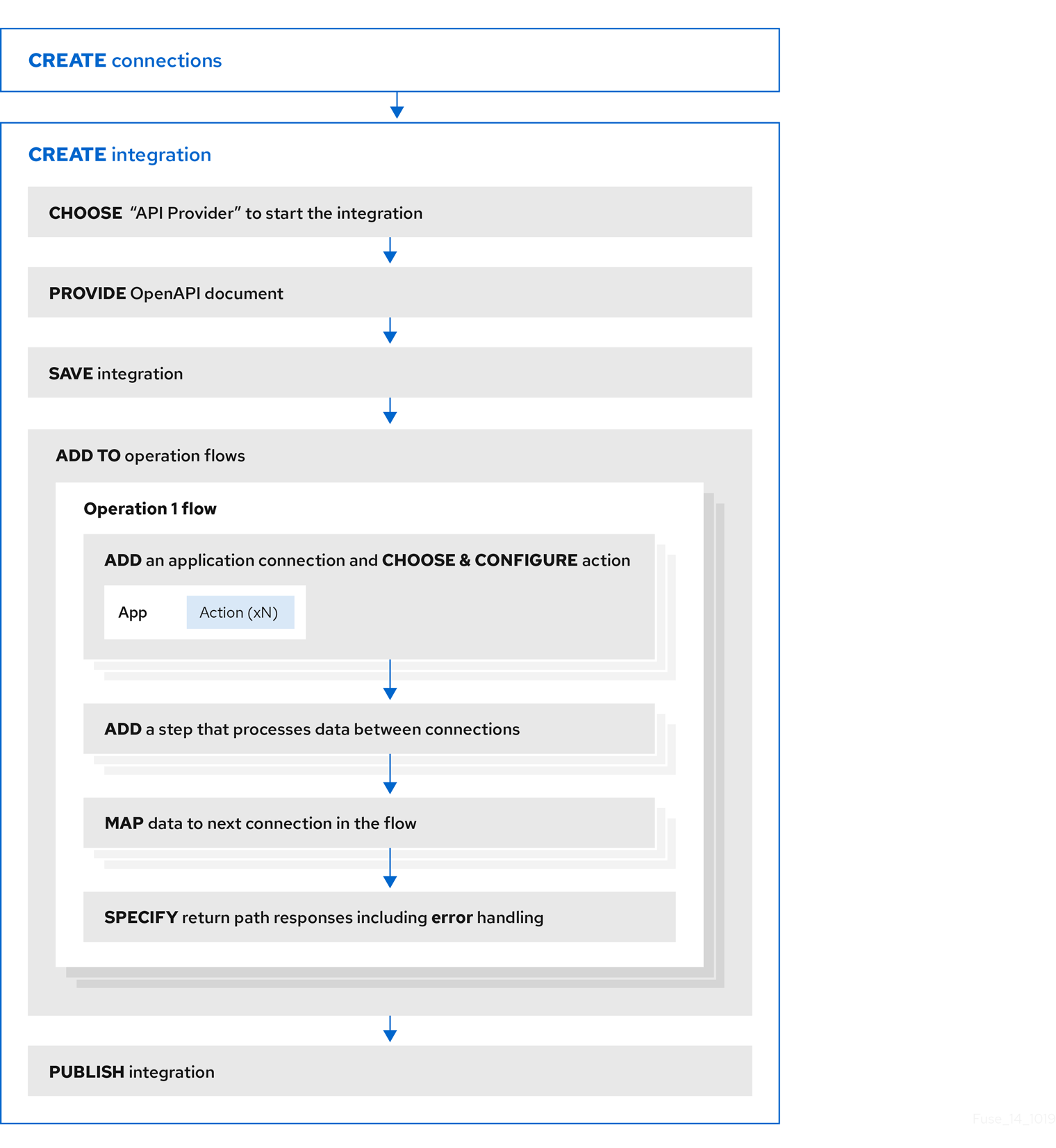
Publishing an API provider integration
After you publish an API provider integration, in the integration’s summary page, Fuse Online displays the external URL for your REST API service. This external URL is the base URL that clients use to call your REST API services.
For Fuse Online environments on OCP, Red Hat 3scale discovery of API provider integrations might be enabled. In this case, 3scale publishes the URL for invoking services.
Testing an API provider integration
To test an API provider integration’s flows, you can use the curl utility. For example, the following curl command triggers execution of the flow for the Get Task by ID operation for the REST API service URL: https://i-task-api-proj319352.6a63.fuse-ignite.openshiftapps.com/api/.
The HTTP GET command is the default request so there is no requirement to specify GET. The last part of the URL specifies the ID of the task to get:
curl -k https://i-task-api-proj319352.6a63.fuse-ignite.openshiftapps.com/api/todo/1
5.2. How OpenAPI operations relate to API provider integration flows
An API provider integration’s OpenAPI document defines the operations that REST API clients can call. Each OpenAPI operation has its own API provider integration flow. Consequently, each operation can also have its own REST API service URL. Each URL is defined by the API service’s base URL and optionally by a subpath. REST API calls specify an operation’s URL to trigger execution of the flow for that operation.
Your OpenAPI document determines which HTTP verbs (such as GET, POST, DELETE and so on) you can specify in calls to your REST API service URLs. Examples of calls to API provider URLs are in the instructions for trying out the API provider quickstart example.
Your OpenAPI document also determines the possible HTTP status codes that an operation can return. An operation’s return path can handle only the responses that the OpenAPI document defines. For example, an operation that deletes an object based on its ID might define these possible responses:
"responses": {
  "204": {
           "description": "Task deleted"
         },
  "404": {
           "description": "No Record found with this ID"
         },
  "500": {
            "description": "Server Error"
        }
}
Illustration of an API provider integration example
The following diagram shows an API provider integration that processes data about people. An external REST API client invokes the REST API URLs that are deployed by the API provider integration. Invocation of a URL triggers execution of the flow for one REST operation. This API provider integration has 3 flows. Each flow can use any connection or step that is available in Fuse Online. The REST API along with its flows is one Fuse Online API provider integration, which is deployed in one OpenShift pod.
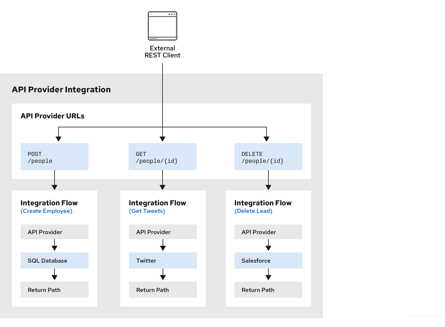
Editing the OpenAPI document while creating an API provider integration
After you specify an OpenAPI document for your API provider integration, you can update the document as needed while you define the execution flows for the API operations. To do this, click View/Edit API Definition in the upper right of a page in which you are editing the API provider integration. This displays your OpenAPI document in the API Designer editor. Edit and save the document to make changes that are reflected in Fuse Online.
Considerations while editing the OpenAPI document:
operationIdproperties for synchronizationSynchronization between the versions of the OpenAPI document in the API Designer editor and in the Fuse Online integration editor depend on a unique
operationIdproperty that is assigned to each operation that is defined in the document. You can assign a specificoperationIdproperty value to each operation, or use the one that Fuse Online generates automatically.Request and response definitions
In each operation’s definition, you can supply a JSON schema that defines the operation’s request and response. Fuse Online uses the JSON schema:
- As the basis for the operation’s input and output data shapes
- To display operation fields in the data mapper
No cyclic schema references
A JSON schema for an API provider integration operation cannot have cyclic schema references. For example, a JSON schema that specifies a request or response body cannot reference itself as a whole nor reference any part of itself through intermediate JSON schemas.
5.3. Creating an API provider integration
To create an API provider integration, provide an OpenAPI document (.json, .yaml, or .yml file) that defines the operations that the integration can perform. Fuse Online creates an execution flow for each operation. Edit the flow for each operation to add connections and steps that process integration data according to the requirements for that operation.
Prerequisites
You are able to provide or define an OpenAPI document for the REST API operations that you want the integration to perform.
To experiment, download the raw version of the
task-api.jsonfile, which is an OpenAPI document for an API provider quickstart. You can upload this file when Fuse Online prompts you to provide an OpenAPI document. Alternatively, you can specify the URL for the rawtask-api.jsonfile, which is https://raw.githubusercontent.com/syndesisio/syndesis-quickstarts/1.11/api-provider/task-api.json.- You have a plan for the flow for each OpenAPI operation.
- You created a connection for each application or service that you want to add to an operation’s flow.
Procedure
- In Fuse Online, in the left navigation panel, click Integrations.
- Click Create Integration.
- On the Choose a connection page, click API Provider.
On the Start integration with an API call page:
- If you have an OpenAPI document that defines the REST API operations, upload the OpenAPI document.
- If you need to define the OpenAPI document, select Create a new OpenAPI 3.x document or Create a new OpenAPI 2.x document.
Click Next.
If you uploaded a document, review or edit it:
- Click Review/Edit to open the API Designer editor.
Review and edit as needed.
Optionally, if your document uses the OpenAPI 2 specification, you can click Convert to OpenAPI 3 if you want the API Designer to convert your document to conform with the OpenAPI 3 specification.
- In the upper right, click Save or Cancel to close the editor.
- Click Next.
If you are creating a document, then in the API Designer editor that Fuse Online opens:
- Define the OpenAPI document as described in Design and develop an API definition with API Designer.
- In the upper right, click Save, which closes the editor.
- Click Next.
Result
Fuse Online displays a list of the operations that the OpenAPI document defines.
Next step
For each operation, define a flow that executes that operation.
5.4. Defining the operation flows for an API provider integration
The OpenAPI document that defines your REST API service defines the operations that the service can perform. After you create an API provider integration, you can edit the flow for each operation.
Each operation has exactly one flow. In an operation flow, you can add connections to other applications and services, as well as steps that operate on data between connections.
As you add to operation flows, you might find that you need to update the OpenAPI document that the API provider integration is based on. To do this, click View/Edit API Definition in the upper right of a page in which you are editing your API provider integration. This displays your document in the API Designer editor. In your OpenAPI definition, as long as each operation has a unique operationId property, you can save your updates in API Designer and Fuse Online can synchronize the API provider integration’s flow definitions to have your updates.
Prerequisites
- You created an API provider integration, gave it a name, and saved it.
- You created a connection to each application or service that you want an operation flow to connect to. For details, see the information about creating connections.
- Fuse Online is displaying the list of operations that the API defines.
Procedure
- In the Operations list page, for the operation whose flow you want to define, click Create flow.
For each connection that you want to add to this flow:
- In the flow visualization, click the plus sign to add a connection at that location.
- Click the connection that you want to add.
- Select the action that you want this connection to perform.
- Configure the action by entering data in the labeled fields.
- Click Next.
Add all desired connections to the flow before you continue.
In this operation flow, to process data between connections:
- In the flow visualization, click the plus sign where you want to add a step.
- Click the step that you want to add.
- Configure the step by entering data in the labeled fields.
Click Next.
For help, see Adding steps between connections.
If you want to add another step that processes data between connections, repeat this subset of instructions.
Map data to fields in the next connection:
-
In the flow visualization, check for data type mismatch
icons, which indicate that the connection cannot process the incoming data. You need to add a data mapper step here.
For each data mismatch icon in the flow visualization:
- Click the plus sign that is just before that step.
- Click Data Mapper.
- Define the needed mappings. For help, see Mapping integration data to fields in the next connection.
- Click Done to add the data mapper step to the flow.
-
In the flow visualization, check for data type mismatch
In the flow visualization, on the Provided API Return Path step, click Configure.
Every API provider integration finishes each operation flow by sending a response to the REST API caller that triggered execution of the operation flow. The response contains one of the return codes that you configure for the Provided API Return Path step that finishes the operation’s flow. Configure the return path step as follows:
- Under Default Response, in the Return Code field, accept the default response that Fuse Online displays, or click the down caret and scroll to select the default response that you want. The flow sends this response when execution of the operation flow does not return any of the configured error responses. Typically, the default response return code indicates a successful operation.
Under Error Handling, indicate whether you want to include the error message in the body of the returned message.
During development, you typically want to return the error message. In production, however, you might want to hide the error message if it contains sensitive or proprietary information. The error message is a JSON formatted string that contains
responseCode,category,message, anderrorelements, for example:{ responseCode: 404, category: "ENTITY_NOT_FOUND_ERROR", message: "SQL SELECT did not SELECT any records" error: SYNDESIS_CONNECTION_ERROR }Note that during development, the most reliable way to know that an error happened is to check the
HTTP_RESPONSE STATUSheader in the response to the caller. You can also check the integration pod’s log forINFOmessages. The integration’s Activity log shows a successful exchange and errors are not always visible in the Activity log.Under Error Response Codes, Fuse Online displays an entry for each error that a connection in the flow might return. For each error, accept the 200 All is good default return code or click to select another HTTP status return code.
The return codes that you can select from, are the return codes that the OpenAPI document defines for the operation that this flow executes. If Fuse Online does not display a return code that you need, you can edit the OpenAPI document to add it.
To do this, in the upper right, click View/Edit API Definition. Edit the OpenAPI document as needed. When you are done, save the OpenAPI document. Fuse Online returns to editing the Provided API Return Path and reflects any changes that you saved.
- Click Next to complete configuration of the return path.
When this flow has all needed connections and steps and there are no data mismatch icons, or when you no longer want to edit the flow for now, do one of the following:
- Publish — To start running the integration, in the upper right, click Publish. This builds the integration, deploys the REST API service to OpenShift, and makes the integration available to be executed. You can publish the integration each time that you complete the creation of an operation’s flow or each time that you edit an operation’s flow.
- Save — To display the list of operations, in the upper right, click Save.
Repeat this procedure to edit another operation’s flow.
Testing API provider integrations
Testing API provider integrations running on one of these platforms:
- OpenShift Online
- OpenShift Dedicated
- OpenShift Container Platform when API discovery is disabled
You can use the
curlutility to confirm that the integration is working as expected. In thecurlcommand, specify the external URL that Fuse Online displays after it publishes the API provider integration. For examples of doing this, see Testing the example API provider quickstart integration.Testing API provider integrations running on OpenShift Container Platform when API discovery is enabled
Red Hat 3scale publishes your API provider integration. To test the integration, open the 3scale dashboard to obtain the integration’s URL.
You can disable discovery for an API provider integration if, for example, you do not want Red Hat 3scale to control access to the integration’s API or you want to test the API provider integration in Fuse Online. If you disable discovery, Fuse Online republishes the integration and provides an external URL for invoking and testing integration execution. To do this, in Fuse Online go to the integration’s summary page. On this page, click Disable discovery. Fuse Online republishes the integration and provides the integration’s URL. For examples of how to test an integration, see Testing the example API provider quickstart integration. After testing, you can re-enable discovery for the API provider integration so that 3scale publishes it.
You can enable or disable discovery for each API provider integration.
5.5. Importing and publishing the example API provider quickstart integration
Fuse Online provides an API provider quickstart integration that you can import into your Fuse Online environment. This quickstart includes an OpenAPI document for a task management API. After importing the quickstart integration, you can examine the flows and then publish the integration. After you complete the procedure described below, the Task API integration is running and ready to be executed.
The API provider quickstart helps you quickly learn how to configure, publish, and test an API provider integration. But it is not a real-world example of how useful an API provider integration can be. For a real-world example, suppose that you already used Fuse Online to publish several simple integrations. You could define an OpenAPI document for triggering execution of those integrations. To do this, you would edit the flow for each OpenAPI operation to be almost the same as the simple integrations that you already published.
Prerequisites
- Fuse Online is open in a browser.
-
The Fuse Online environment must include the
Todosample app as described in Adding a sample app to a Fuse Online environment running on OCP.
Procedure
Import the Task API quickstart integration:
-
Go to https://github.com/syndesisio/syndesis-quickstarts/tree/1.11/api-provider and download
TaskAPI-export.zip. - In Fuse Online, in the left navigation panel, click Integrations.
- In the upper right, click Import.
-
Drag the
TaskAPI-export.zipfile that you downloaded to the Import page. Fuse Online indicates that it has successfully imported the file. - In the left navigation panel, click Integrations to see an entry for the Task API integration that you just imported. Although the entry indicates that configuration is required, this integration is ready to publish.
-
Go to https://github.com/syndesisio/syndesis-quickstarts/tree/1.11/api-provider and download
- Click Edit Integration to view the list of the operations that this API provides.
To examine the flows for each operation:
Click its Edit flow button to display the visualization for that flow.
Each flow already has a database connection, one or more data mapper steps, and a Provided API Return Path step that finishes the flow.
- For the Invoke SQL step, click Configure to see the SQL statement that the connection executes. Then click Cancel to return to that operation’s visualization flow.
- For a data mapper step, click Configure to see the mappings. Then click Cancel to return to the visualization.
- For the Provided API Return Path step, which is the last step in every operation’s flow, click Configure to see the HTTP return codes that the operation might send to the caller. Click Cancel to return to the visualization.
- After examining one operation’s flow, click the Integrations> Task API> Operation drop down menu and then select another operation.
- Repeat this subset of steps to examine each flow.
- Click Save and edit the integration name if you want to.
Click Save and Publish.
The summary page for the integration shows publication progress as it assembles, builds, deploys, and starts the integration.
When the Task API integration summary page displays Running, Fuse Online displays the external URL for the Task API service. It looks something like this:
https://i-task-api-fuseonline.apps.openshift.com/This is where Fuse Online makes the Task API service available. REST API calls specify URLs that start with this base URL.
If you are using Fuse Online on OpenShift Container Platform, if the external URL is not on the integration’s summary page, then an administrator has enabled Red Hat 3scale discovery. This means that Red Hat 3scale controls access to the integration’s API and also publishes your API provider integration. To test the integration, open the 3scale dashboard to obtain the integration’s URL.
If you do not want Red Hat 3scale to control access to the integration’s API, you can disable discovery. You do this in Fuse Online by viewing the integration’s summary page. On this page, click Disable discovery. Fuse Online republishes the integration and provides an external URL for invoking integration execution.
You can enable or disable discovery for each API provider integration.
5.6. Testing the example API provider quickstart integration
When the Fuse Online Task API quickstart integration is running, you can invoke curl utility commands that send HTTP requests to the Task API service. How you specify the HTTP request determines the flow that the call triggers.
Prerequisites
- Fuse Online indicates that the Task API integration is Running.
- If your Fuse Online environment is running on OCP, Fuse Online is not configured to expose APIs to 3scale or you disabled discovery for the Task API integration.
Procedure
- In Fuse Online, in the left navigation panel, click Integrations.
- In the Task API integration entry, click View to display the integration’s summary.
- Copy the integration’s external URL.
In a terminal, invoke a command such as the following to assign the integration’s external URL to the
externalURLenvironment variable. Be sure to replace the URL in this sample command with the URL that you copied.export externalURL="https://i-task-api-fuseonline.apps.openshift.com"
Invoke a
curlcommand that triggers execution of the flow for the Create new task operation:curl -k --header "Content-Type: application/json" --request POST --data '{"id":1, "task":"my first task :)!"}' $externalURL-
-kallowscurlto proceed and operate even for server connections that are otherwise considered insecure. -
--headerindicates that the command is sending JSON format data. -
--requestspecifies the HTTPPOSTcommand, which stores data. -
--dataspecifies the JSON format content to be stored. In this example, the content is{"id":1, "task":"my new task!"}. Note that thecompletedfield is not required. -
$externalURLis the URL to invoke.
This command sends an HTTP
POSTrequest to the Task API service, which triggers execution of the Create new task operation’s flow. Flow execution adds a new task to the sample database and returns a message such as the following to indicate what it did:+
{"completed":null,"id":1,"task":"my new task!"}-
Invoke the following
curlcommands to create two more tasks:curl -k --header "Content-Type: application/json" --request POST --data '{"id":2, "task":"my second task :|"}' $externalURL curl -k --header "Content-Type: application/json" --request POST --data '{"id":3, "task":"my third task :("}' $externalURLInvoke a
curlcommand that triggers execution of the flow for the Fetch task by ID operation:curl -k $externalURL/1
To obtain a task, the
curlcommand needs to specify only the URL. The HTTPGETcommand is the default request. The last part of the URL specifies the ID of the task to get.Invoke the following
curlcommand that triggers execution of the flow for the Fetch all tasks operation:curl -k $externalURL
Optionally, invoke a
curlcommand that triggers execution of the flow for the Delete task for ID operation:curl -k -X DELETE $externalURL/3
This command invokes the HTTP
DELETEcommand with the same URL as the command that obtained a task by its ID.
Chapter 6. Creating an integration that is triggered by an HTTP request (Webhook)
You can trigger execution of a simple integration by sending an HTTP GET or POST request to an HTTP endpoint that Fuse Online exposes. The following topics provide details:
- Section 6.1, “General procedure for using the Fuse Online webhook”
- Section 6.2, “Creating an integration that an HTTP request can trigger”
- Section 6.3, “How Fuse Online handles HTTP requests”
- Section 6.4, “Guidelines for an HTTP client that invokes a Fuse Online Webhook”
- Section 6.5, “About the JSON schema for specifying request parameters”
- Section 6.6, “How to specify HTTP requests”
6.1. General procedure for using the Fuse Online webhook
To trigger execution of an integration with an HTTP GET or POST request, you must do the following:
-
Decide whether you want to send a
GETorPOSTrequest to Fuse Online. - Plan your integration to handle this request.
Create the connection that finishes the integration.
Fuse Online provides a Webhook connection that you use as the start connection.
- Create any other connections that you want to add to the integration.
Create the integration:
- Add the Webhook connection as the start connection.
Add the finish connection and then any other connections that are required in the integration. The finish connection and any middle connections handle the HTTP request that triggers execution of the integration. It is up to you to choose and specify the most appropriate HTTP request for accomplishing your goals. Keep the following in mind:
- Add a connection to the application that contains the data that you want to obtain or that contains the data that you want to update.
-
A
GETrequest is limited to specification of key/value parameters. -
A
POSTrequest can provide an arbitrary body, such as an XML or JSON instance. -
Fuse Online returns only an HTTP status header and does not return any data. Consequently, you can define an integration that is triggered by a
GETrequest and that updates data rather than obtaining data. Likewise, you can define an integration that is triggered by aPOSTrequest and that obtains data rather than updating data.
Add a data mapper step after the Webhook connection.
For a
GETrequest, map the parameter fields in the HTTP request to the data fields in the next connection.For a
POSTrequest, you might have specified the output data shape in the request by passing a JSON instance, JSON schema, XML instance, or XML schema. If you did not, then when you add a Webhook connection as the start connection of an integration, Fuse Online prompts you to specify the output data type. If you do not, then the default Webhook connection output data type is in JSON format.- Add any other steps that the integration needs.
- Publish the integration and wait for it to be Running.
- Go to the integration summary page and copy the external URL that Fuse Online provides.
-
Modify this external URL to construct your
GETorPOSTrequest. -
Implement the application that sends the HTTP
GETorPOSTrequest to Fuse Online.
6.2. Creating an integration that an HTTP request can trigger
To trigger execution of an integration with an HTTP GET or POST request, add a Webhook connection as the integration’s start connection.
Procedure
- In the Fuse Online panel on the left, click Integrations.
- Click Create Integration.
- On the Choose a connection page, click the Webhook connection.
On the Choose an action page, select the Incoming Webhook action.
In the Webhook Configuration page, Fuse Online displays the webhook token that Fuse Online generates for this integration.
When you construct the HTTP request, this token is the last part of the URL. After you publish this integration and it is running, Fuse Online displays the Fuse Online external URL, which has this token at the end.
The Webhook Configuration page also includes Default Response and Error Handling sections. The webhook step sends a response to the HTTP client that invoked it. The response contains one of the return codes and, by default, the error message in the body of the returned message.
- Under Default Response, in the Return Code field, accept the default response that Fuse Online displays, or use the drop-down list to select the default response that you want. The flow sends this response when execution of the operation flow does not return any of the configured error responses. Typically, the default response return code indicates a successful operation.
Under Error Handling, indicate whether you want to include the error message in the body of the returned message.
During development, you typically want to return the error message. In production, however, you might want to hide the error message if it contains sensitive or proprietary information. The error message is a JSON-formatted string that contains
responseCode,category,message, anderrorelements, for example:{ responseCode: 404, category: "ENTITY_NOT_FOUND_ERROR", message: "SQL SELECT did not SELECT any records" error: SYNDESIS_CONNECTION_ERROR }Note that during development, the most reliable way to know that an error happened is to check the
HTTP_RESPONSE STATUSheader in the response to the caller. You can also check the integration pod’s log forINFOmessages. The integration’s Activity log shows a successful exchange and errors are not always visible in the Activity log.- For each error that the webhook step might return, accept the default return code or use the drop-down list to select another HTTP status return code.
- Click Next.
In the Specify Output Data Type page:
- Click in the Select Type field, and select JSON schema.
- In the Definition field, paste the JSON schema that defines the data types of the parameters in the HTTP request. See About the JSON schema for specifying request parameters.
- In the Data Type Name field, specify a name for this data type. Although this is optional, if you specify a name, it appears in the data mapper Sources list, which can make it easier to correctly map fields.
- Optionally, in the Data Type Description field, provide some information that helps you distinguish this data type.
- Click Next.
- Add the finish connection to the integration.
- Add any other needed connections.
- Add any other needed steps.
- Immediately after the start connection, add a data mapper step.
- Click Publish, give the integration a name and optionally, a description, and click Save and publish.
6.3. How Fuse Online handles HTTP requests
You can specify an HTTP GET or POST request to trigger execution of a simple integration. Although a GET request usually obtains data and a POST request usually updates data, you can use either request to trigger an integration that does either operation. Any parameters in the request are available for mapping to data fields in the next connection that is in the integration. For details, see About the JSON schema for specifying request parameters.
A Webhook connection only passes the data it receives to the next connection in the integration. When Fuse Online receives an HTTP request, it:
-
Returns an HTTP status header to the requester. When a request successfully triggers execution of an integration, the Fuse Online return code is
201. When a request fails to trigger execution of an integration, the Fuse Online return code is5xx. - Does not return any other data to the requester. In other words, there is no data in the HTTP body of the response that contains the status header.
- Passes the data in the request to the next connection in the integration.
This means that you can define a simple integration that is triggered by a GET request and that updates data rather than obtaining data. Likewise, you can define a simple integration that is triggered by a POST request and that obtains data rather than updating data.
In the integration’s Activity tab, the status of a webhook step is Success every time. This Success status indicates the status of the communication between the Fuse Online} Webhook and the HTTP client that invokes it. This Success status is not an indication that the integration passed successfully nor that any steps are without error. Errors generated by HTTP requests are not visible in the integration’s Activity log.
When you configure a webhook, the Include error message in the return body option is checked by default. When this option is checked, to verify whether the errors generated by HTTP requests are included in the webhook response, send a test request that will generate an error and then check the response header. You can also check the integration pod’s log for INFO messages. Use the following command to view the integration’s pod log, where example-integration-pod is the name of the pod.
oc logs -f pod/example-integration-pod
6.4. Guidelines for an HTTP client that invokes a Fuse Online Webhook
When you implement a client that sends an HTTP request to Fuse Online, your implementation should:
-
Add to the Fuse Online-provided external URL to construct a URL that makes a
GETorPOSTrequest. -
In the URL request, specify HTTP header and query parameter values whose data types adhere to the
io:syndesis:webhookJSON schema. See About the JSON schema for specifying request parameters. When header and query parameters adhere to this data type specification, then you can map parameter fields to fields that the next connection in the integration can process. -
If the request succeeds, handle a returned success code of
201. -
If the request fails, handle an HTTP
5xxerror code. - Not expect any other response from Fuse Online. In other words, sending the request does not directly return data to the requesting client other than the return code.
6.5. About the JSON schema for specifying request parameters
In an integration, you typically map header and query parameters in the HTTP request to data fields that the next connection in the integration can process. To make this possible, when you add the Webhook connection to the integration, specify the output data type in a JSON schema that has the following structure:
{
  "$schema": "http://json-schema.org/schema#",
   "id": "io:syndesis:webhook",
   "type": "object",
   "properties": {
      "parameters": {
         "type": "object",
         "properties": { 1
         }
      },
      "body": {
         "type": "object",
         "properties": { 2
         }
      }
   }
}
To add the data structures that you need, in the JSON instance for your HTTP request:
While all data that an HTTP client sends is available in the integration, when a Webhook connection’s data shape conforms to this JSON schema, then query parameters and body content are available for mapping.
For examples, see How to specify HTTP requests.
6.6. How to specify HTTP requests
The following examples show how to specify HTTP requests for the Fuse Online Webhook.
Webhook example of POST request with only HTTP body
Consider an integration that starts with a Webhook connection and then creates a row in the Todo table of the Fuse Online-provided database:

During creation of this integration, when you add the Webhook start connection, you specify its output data type with a JSON instance that has this content: {"todo":"text"}:
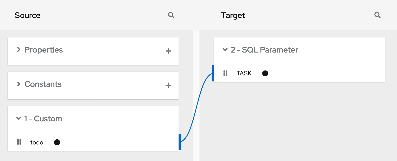
When you add the PostgresDB connection as the finish connection, you select the Invoke SQL action and specify this SQL statement:
INSERT INTO TODO (TASK) VALUES (:#TASK)
After you add the database connection, you add a mapping step:
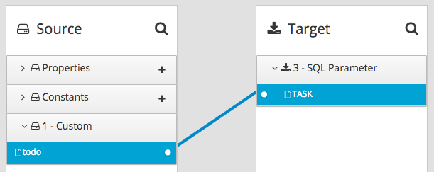
You save and publish the integration. When it is running, you can copy the external URL that Fuse Online provides:
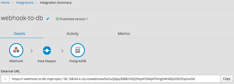
To understand the parts of the external URL, consider this sample URL:
https://i-webhook-to-db-myproject.192.168.64.4.nip.io/webhook/bvGvQdpq308BcHIQQYeysFOK4plFISmghNHkRyOOk3YppitvOd
| Value | Description |
|---|---|
|
| Fuse Online always inserts this value at the beginning of the URL. |
|
| The name of the integration. |
|
| The OpenShift namespace that contains the pod that is running the integration. |
|
| The DNS domain that is configured for OpenShift. This indicates the Fuse Online environment that is providing the webhook. |
|
| Appears in each Webhook connection URL. |
|
| Webhook connection token that Fuse Online provides when you add a Webhook connection to an integration. The token is a random string that provides security in that it makes the URL hard to discern, which prevents anyone else from sending a request. In a request, you can specify the token that Fuse Online provides or you can define your own. If you define your own, ensure that it is hard to guess. |
As you can see in the external URL, Fuse Online constructs the host name from the name of the integration, the name of the OpenShift namespace, and the OpenShift DNS domain. Fuse Online removes illegal characters and converts spaces to hyphens. In the sample external URL, this is the host name:
https://i-webhook-to-db-myproject.192.168.64.4.nip.io
To use curl to invoke the webhook, you would specify the command as follows:
curl -H 'Content-Type: application/json' -d '{"todo":"from webhook"}' https://i-webhook-to-db-myproject.192.168.64.4.nip.io/webhook/bvGvQdpq308BcHIQQYeysFOK4plFISmghNHkRyOOk3YppitvOd
-
The
-Hoption specifies the HTTPContent-Typeheader. -
The
-doption sets the HTTP method toPOSTby default.
Execution of this command triggers the integration. The database finish connection inserts a new task into the tasks table. To see this, display the Todo app at, for example, https://todo-myproject.192.168.64.4.nip.io, Click Update and you should see from webhook as a new task.
Webhook example of POST request with query parameters
For this example, consider the same integration as in the previous example:
But in this example, you define the Webhook connection output data type by specifying a JSON schema with this content:
{
  "type": "object",
  "definitions": {},
  "$schema": "http://json-schema.org/draft-07/schema#",
  "id": "io:syndesis:webhook",
  "properties": {
    "parameters": {
      "type": "object",
      "properties": {
        "source": {
          "type": "string"
        },
        "status": {
          "type": "string"
        }
      }
    },
    "body": {
      "type": "object",
      "properties": {
        "company": {
          "type": "string"
        },
        "email": {
          "type": "string"
        },
        "phone": {
          "type": "string"
        }
      }
    }
  }
}
In this JSON schema:
-
The
idmust be set toio.syndesis.webhook. -
The
parameterssection must specify the HTTP query parameters. -
The
bodysection must specify the body content and it can be as complex as you need it to be. For example, it can define nested properties as well as arrays.
This provides the information that the Webhook connector needs to prepare the content for the next step in the integration.
To use curl to send an HTTP request, invoke a command such as the following:
curl -H 'Content-Type: application/json' -d '{"company":"Gadgets","email":"sales@gadgets.com","phone":"+1-202-555-0152"}'https://i-webhook-params-to-db-myproject.192.168.42.235.nip.io/webhook/ZYWrhaW7dVk097vNsLX3YJ1GyxUFMFRteLpw0z4O69MW7d2Kjg?source=web&status=new
When the Webhook connection receives this request it creates a JSON instance that looks like this:
{
  "parameters": {
    "source": "web",
    "status": "new"
  },
  "body": {
    "company": "Gadgets",
    "email": "sales@gadgets.com",
    "phone": "+1-202-555-0152"
  }
}
It is this internal JSON instance that enables the following mapping:
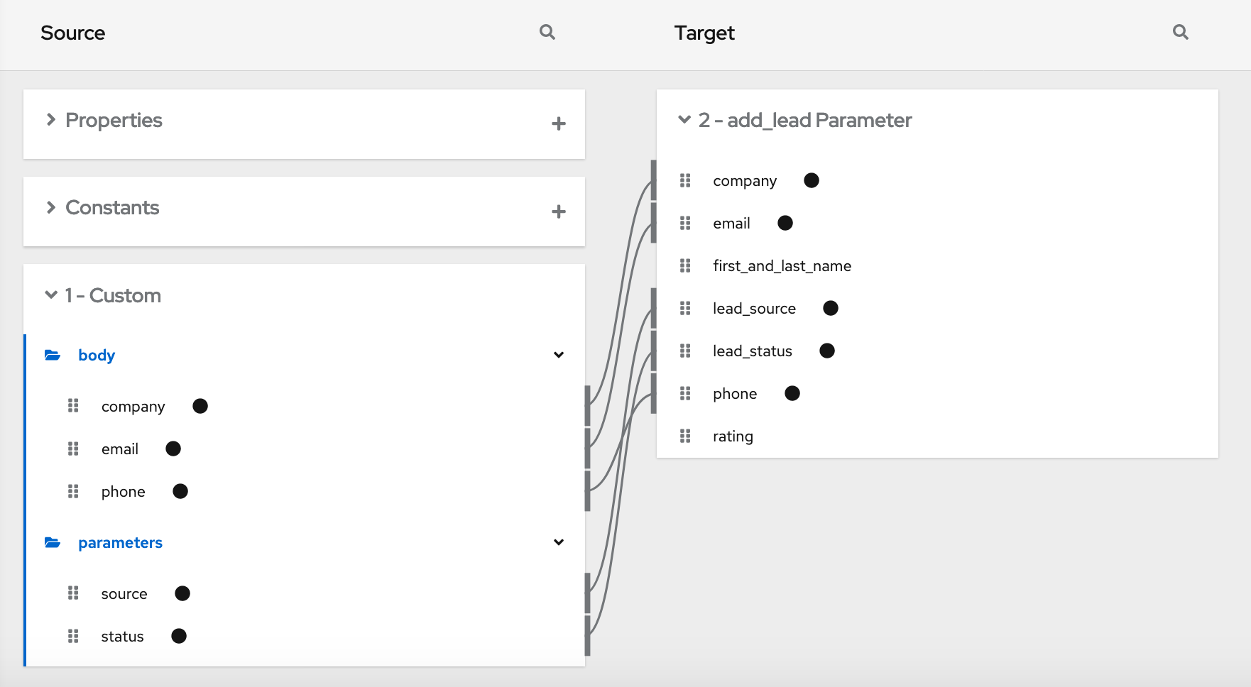
Webhook examples with GET
To trigger an integration with a GET request that does not provide input data, specify the Webhook connection output data shape as a JSON instance with the definition '{}'. You can then invoke the following curl command, which does not specify query parameters:
curl 'https://i-webhook-params-to-db-myproject.192.168.42.235.nip.io/webhook/ZYWrhaW7dVk097vNsLX3YJ1GyxUFMFRteLpw0z4O69MW7d2Kjg'
You can change the previous POST example to send a GET request with query parameters but no body. You would specify the Webhook connection output data shape as a JSON schema with the definition as shown below.
{
  "type": "object",
  "definitions": {},
  "$schema": "http://json-schema.org/draft-07/schema#",
  "id": "io:syndesis:webhook",
  "properties": {
    "parameters": {
      "type": "object",
      "properties": {
        "source": {
          "type": "string"
        },
        "status": {
          "type": "string"
        }
      }
    }
  }
}
Here is the curl command that sends the GET request:
curl 'https://i-webhook-params-to-db-myproject.192.168.42.235.nip.io/webhook/ZYWrhaW7dVk097vNsLX3YJ1GyxUFMFRteLpw0z4O69MW7d2Kjg?source=web&status=new'`
Chapter 7. Mapping integration data to fields for the next connection
In most flows, you need to map data fields that have already been obtained or processed to data fields that the next connection in the flow can process. Fuse Online provides a data mapper to help you do this. In a flow, at each point where you need to map data fields, add a data mapper step.
The data mapper displays the largest possible set of source fields that can be provided by the previous integration step. However, not all connections provide data in each displayed source field. For example, a change to a third-party application might discontinue providing data in a particular field. As you create an integration, if you notice that data mapping is not behaving as you expect, ensure that the source field that you want to map contains the data that you expect.
Details for mapping data fields are in the following topics:
- Section 7.1, “Viewing the mappings in a step”
- Section 7.2, “Identifying where data mapping is needed”
- Section 7.3, “Finding the data field that you want to map”
- Section 7.4, “Mapping one source field to one target field”
- Section 7.5, “Example of missing or unwanted data when combining or separating fields”
- Section 7.6, “Combining multiple source fields into one target field”
- Section 7.7, “Separating one source field into multiple target fields”
- Section 7.8, “About data types and collections in the data mapper”
- Section 7.9, “Using the data mapper to process collections”
- Section 7.10, “About mapping between collections and non-collections”
- Section 7.11, “Transforming source or target data”
- Section 7.12, “About transformations on multiple source values before mapping to one target field”
- Section 7.13, “Applying conditions to mappings”
- Section 7.14, “Descriptions of available transformations”
- Section 7.15, “Troubleshooting data mapping”
7.1. Viewing the mappings in a step
While you are adding or editing a data mapper step, you can view the mappings already defined in this step. This option lets you check whether the correct mappings are in place.
Prerequisites
- You are creating or editing an integration.
- You are adding a data mapper step. That is, the data mapper is visible.
Procedure
-
To see a table view of the mappings, click
 .
.
-
To dismiss the table view of mappings and redisplay the source and target fields, click
 .
.
7.2. Identifying where data mapping is needed
Fuse Online displays warning icons to indicate where a flow requires data mapping.
Prerequisites
- You are creating or editing a flow.
- The flow contains all connections that it requires.
Procedure
-
In the flow visualization, look for any
icons.
- Click the icon to see the Data Type Mismatch notification.
- In the message, click Add a data mapping step, which displays the data mapper.
7.3. Finding the data field that you want to map
In a flow with relatively few steps, mapping data fields is easy and intuitive. In more complex flows or in flows that handle large sets of data fields, mapping from source to target is easier when you have some background about how to use the data mapper.
The data mapper displays two columns of data fields:
- Source is a list of the data fields that are obtained or processed in all previous steps in the flow.
- Target is a list of the data fields that the next connection in the flow expects and can process.
To quickly find the data field that you want to map, you can do any of the following:
Search for it.
The Sources panel and the Target panel each have a search field at the top. If the search field is not visible, click
 at the top right of the Sources or Target panel.
Type the names of the fields that you want to map. In the Sources search field, type the name of the source field. In the Target search field, type the name of the field that you want to map to.
-
Use the
 and
and
 options to filter the visible fields.
Expand and collapse folders to limit the visible fields.
To view the data fields available in a particular step, expand the folder for that step.
As you add steps to a flow, Fuse Online numbers and renumbers them to indicate the order in which Fuse Online processes the steps. When you are adding a data mapper step, the step numbers appear in the folder labels in the Sources panel and in the Target panel.
-
If you want to view the data type for each field, click
 to display (or hide) the data types in each field’s label. The folder label also displays the name of the data type that is output by that step. The folder label also displays the name of the data type that is output by that step. Connections to applications such as Twitter, Salesforce, and SQL define their own data types. For connecting to applications such as Amazon S3, AMQ, AMQP, Dropbox, and FTP/SFTP, you define the connection’s input and/or output type when you add the connection to a flow and select the action that the connection performs. When you specify the data type, you also give the type a name. The type name you specify appears as the name of a folder in the data mapper. If you specified a description when you declared the data type, then the type description appears when you hover over the step folder in the mapper.
7.4. Mapping one source field to one target field
The default mapping behavior maps one source field to one target field. For example, map the Name field to the CustomerName field.
Procedure
In the Sources panel:
If necessary, expand a step to see the data fields that it provides.
When there are many source fields, you can search for the field of interest by clicking the
and then typing the name of the data field in the search field.
-
Click the data field that you want to map from and then click
 . The Mapping Details panel opens.
In the Target panel, find the data field that you want to map to and then click
 .
.
The data mapper displays a line that connects the two fields that you just selected.
Optionally, preview the data mapping result. This option is useful when you add a transformation to the mapping or when the mapping requires a type conversion.
-
In the upper right of the data mapper, click
 to display a text input field on the source field and a read-only result field on the target field.
- In the source field’s data input field, type an example input value. The mapping result appears in the read-only field on the target field.
- Optionally, to see the result of a transformation, add a transformation in the Mapping Details panel.
-
To hide the preview fields click
again.
-
In the upper right of the data mapper, click
Optionally, to confirm that the mapping is defined, click
to display the defined mappings.
You can also preview data mapping results in this view. .. If preview fields are not visible, click
. .. Enter data as described in the previous step.
+ In the table of defined mappings, preview fields appear for only the selected mapping.
- To see preview fields for another mapping, select it.
-
Click
again to display the data field panels.
- In the upper right, click Done to add the data mapper step to the integration.
Troubleshooting tip
The data mapper displays the largest possible set of source fields that can be provided by the previous integration step. However, not all connections provide data in each displayed source field. For example, a change to a third-party application might discontinue providing data in a particular field. As you create an integration, if you notice that data mapping is not behaving as you expect, ensure that the source field that you want to map contains the data that you expect.
7.5. Example of missing or unwanted data when combining or separating fields
In a data mapping, you might need to identify missing or unwanted data when a source or target field contains compound data. For example, consider a long_address field that has this format:
number street apartment city state zip zip+4 country
Suppose that you want to separate the long_address field into discrete fields for number, street, city, state, and zip. To do this, you select long_address as the source field and then select the target fields. You then add padding fields at the locations for the parts of the source field that you do not want. In this example, the unwanted parts are apartment, zip+4, and country.
To identify the unwanted parts, you need to know the order of the parts. The order indicates an index for each part of the content in the compound field. For example, the long_address field has 8 ordered parts. Starting at 1, the index of each part is:
| 1 | number |
| 2 | street |
| 3 | apartment |
| 4 | city |
| 5 | state |
| 6 | zip |
| 7 | zip+4 |
| 8 | country |
In the data mapper, to identify apartment, zip+4, and country as missing, you add padding fields at indexes 3, 7, and 8. See Combining multiple source fields into one target field.
Now suppose that you want to combine source fields for number, street, city, state, and zip into a long_address target field. Further suppose that there are no source fields to provide content for apartment, zip+4, and country. In the data mapper, you need to identify these fields as missing. Again, you add padding fields at indexes 3, 7, and 8. See Separating one source field into multiple target fields.
7.6. Combining multiple source fields into one target field
In a data mapper step, you can combine multiple source fields into one compound target field. For example, you can map the FirstName and LastName fields to the CustomerName field.
Prerequisite
For the target field, you must know what type of content is in each part of this compound field, the order and index of each part of the content, and the separator between parts, such as a space or comma. See Example of missing or unwanted data.
Procedure
-
In the Target panel, click the field into which you want to map more than one source field and then click
. The Mapping Details panel opens.
In the Mapping Details panel,from the Source drop-down list, select one or more data fields that you want to map to.
When you are done you should see a line from each of the source fields to the target field.
In the Mapping Details panel, above Sources, the data mapper displays the default multiplicity transformation, which is Concatenate. This indicates that execution of the mapping applies the Concatenate transformation to the values in the selected source fields and maps the concatenated value to the selected target field.
NoteFor information about other transformations that you can apply to multiple source values see
In the Mapping Details panel, configure the mapping as follows:
- Under Sources, in the Delimiter field, accept or select the character that the data mapper inserts in the target field between the content from different source fields. The default is a space.
-
Optionally, in each source field entry, you can click
 to apply a transformation to the source field value before it gets mapped to the target field.
Under Sources, check the order of the entries for the source fields that you selected. The entries must be in the same order as the corresponding content in the compound target field.
If the entries are not in the correct order, change the index number for the field entries to achieve the same order.
If you mapped a source field to each part of the compound target field, skip the next step.
For each source field entry that does not already have the same index as the corresponding data in the target field, edit the index to be the same. Each source field entry must have the same index as the corresponding data in the target field. The data mapper automatically adds padding fields as needed to indicate missing data.
If you accidentally create too many padding fields, click
 for each extra padding field to delete it.
-
Optionally, under Targets, click
to map the content into the target field and then apply a transformation as described in Transforming source or target data.
Optionally, preview the data mapping result:
-
Click
to display a text input field on each source field for the currently selected mapping and a read-only result field on the target field of the currently selected mapping.
In the source data input fields, type sample values.
If you reorder the source fields or add a transformation to the mapping then the result field on the target field reflects this. If the data mapper detects any errors, it displays informative messages at the top of the Mapping Details panel.
Hide the preview fields by clicking
again.
If you redisplay the preview fields, any data that you entered in them is still there and it remains there until you exit the data mapper.
-
Click
To confirm that the mapping is correctly defined, click
to display (in table format) the mappings defined in this step. A mapping that combines the values of more than one source field into one target field looks like this:
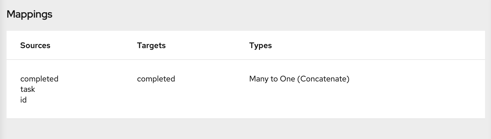 .
.
You can also preview mapping results in this view. Click
and then type text as described in the previous step. Preview fields appear for only the selected mapping. Click another mapping in the table to view preview fields for it.
Additional resource
Example of adding padding fields: Separating one source field into multiple target field.
Although that example is for a one-to-many mapping, the principles are the same.
7.7. Separating one source field into multiple target fields
In a data mapper step, you can separate a compound source field into multiple target fields. For example, map the Name field to the FirstName and LastName fields.
Prerequisite
For the source field, you must know what type of content is in each part of this compound field, the order and index of each part of the content, and the separator between parts, such as a space or comma. See Example of missing or unwanted data.
Procedure
-
In the Sources panel, click the field whose content you want to separate and then click
.
In the Mapping Details panel, from the Target drop-down list, select the data fields that you want to map to.
When you are done selecting target fields, you should see lines from the source field to each of the target fields that you selected.
At the top of the Mapping Details panel, the data mapper displays Split to indicate that execution of the mapping splits the source field value and maps it to multiple target fields. * Under Targets, there is an entry for each target field that you selected.
In the Mapping Details panel, configure the mapping as follows:
- Under Sources, in the Delimiter field, accept or select the character in the source field that indicates where to separate the source field values. The default is a space.
-
Optionally, click
to apply a transformation to the source field value before it gets mapped to the target field.
Under Targets, check the order of the entries for the target fields that you selected. The entries must be in the same order as the corresponding content in the compound source field. It does not matter whether you did not specify a target field for one or more parts of the content in the source field.
If the entries are not in the correct order, change the index number for the field entries to achieve the same order.
If you mapped each part of the compound source field to a target field, then skip to the next step.
If the source field contains data that you do not need, then in the Mapping Details panel, edit the index of each target field that does not already have the same index as the corresponding data in the source field. Each target field entry must have the same index that the corresponding data has in the source field. The data mapper automatically adds padding fields as needed to indicate unwanted data.
See the example at the end of this procedure.
-
Optionally, click
to map the content into the target field and then apply a transformation as described in Transforming source or target data.
Optionally, preview the data mapping result:
-
Click
to display a text input field on the source field and read-only result fields on each target field.
In the source field’s data input field, type a smaple value. Be sure to enter the separator character between the parts of the field. The mapping result appears in the read-only fields for the target fields.
If you reorder the target fields or add a transformation to a target field then the result fields on the target fields reflect this. If the data mapper detects any errors, it displays informative messages at the top of the Mapping Details panel.
Hide the preview fields by clicking
again.
If you redisplay the preview fields, any data that you entered in them is still there and it remains there until you exit the data mapper.
-
Click
To confirm that the mapping is correctly defined, click
to display the mappings defined in this step. A mapping that separates the value of a source field into multiple target fields looks like this:
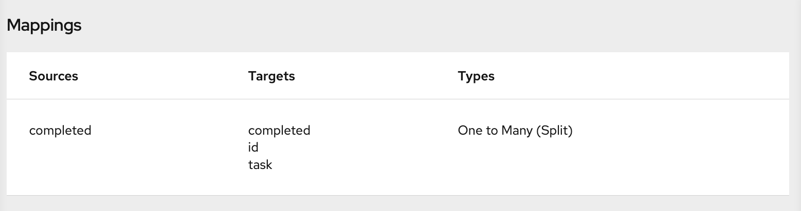 .
.
You can also preview mapping results in this view. Click
, and then type text as described in the previous step. Preview fields appear for only the selected mapping. Click another mapping in the table to view preview fields for it.
Example of separating one field into multiple fields
Suppose that the source data contains one address field and it uses commas to separate the content parts, for example:
77 Hill Street, Brooklyn, New York, United States, 12345, 6789
In an address field, the parts of the content have these indexes:
| Content | Index |
|---|---|
| Number and street | 1 |
| City | 2 |
| State | 3 |
| Country | 4 |
| Zip code | 5 |
| Zip+4 | 6 |
Now suppose that the target data has four fields for an address:
number-and-street
city
state
zip
To define the mapping, you do the following:
-
Select the source field and then click
.
- In the Mapping Details panel, in the Sources section, select the delimiter, which is a comma in this example.
- Select the four target fields.
After you do this, in the Mapping Details panel under Targets, there is an entry for each target field that you selected, for example:
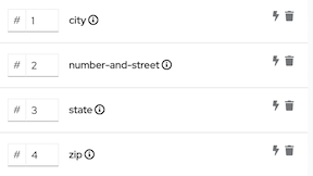 .
.
The data mapper displays the target entries in the order in which they appear in the data mapper, which is alphabetical. You need to change this order so that it mirrors the order in the source field. In this example, the source field contains the number-and-street content before the city content. To correct the order of the target entries, edit the city index field to be 2. The result looks like this:
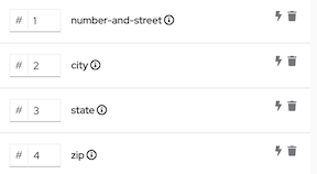 .
.
In the target field entries, the index numbers indicate the part of the source field that will be mapped to this target field. One of the index values needs to change to achieve the correct target field value. Consider each target field:
-
number-and-street— In the source field, the number and street content has an index of 1. It is correct to map the index 1 source to thenumber-and-streettarget field. No changes are needed in this target entry. -
city— In the source field, the city content has an index of 2. This target entry is also correct as it is. -
state— In the source field, the state content has an index of 3. This target entry is also correct as it is. -
zip— In the source field, the zip code content has an index of 5. The target field entry index of 4 is wrong. If you do not change it, during execution, the country part of the source field gets mapped to theziptarget field. You need to change the index to 5. This instructs the data mapper to map the index 5 source content to theziptarget field. After you change the index, the data mapper adds a padding field with an index of 4. The result looks like this:
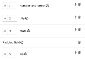 .
.
This mapping is now complete. Although the source field has additional content at index 6, (zip+4), the target does not need the data and nothing needs to be done.
7.8. About data types and collections in the data mapper
In the data mapper, a field can be:
-
A primitive type that stores a single value. Examples of primitive types include
boolean,char,byte,short,int,long,float, anddouble. A primitive type is not expandable because it is a single field. - A complex type that consists of multiple fields of different types. You define the child fields of a complex type at design time. In the data mapper, a complex type is expandable so that you can view its child fields.
Each type of field (primitive and complex) can also be a collection. A collection is a single field that can have multiple values. The number of items in a collection is determined at runtime. At design time, in the data mapper, a collection is indicated by
![]() . Whether a collection is expandable in the data mapper interface is determined by its type. When a collection is a primitive type, it is not expandable. When a collection is a complex type, then the data mapper is expandable to display the collection’s child fields. You can map from/to each field.
. Whether a collection is expandable in the data mapper interface is determined by its type. When a collection is a primitive type, it is not expandable. When a collection is a complex type, then the data mapper is expandable to display the collection’s child fields. You can map from/to each field.
Here are some examples:
-
IDis a primitive type field (int). At runtime, an employee can have only oneID. For example,ID=823. Therefore,IDis a primitive type that is not also a collection. In the data mapper,IDis not expandable. -
emailis a primitive type field (string). At runtime, an employee can have multipleemailvalues. For example,email<0>=aslan@home.comandemail<1>=aslan@business.com. Therefore,emailis a primitive type that also is a collection. The data mapper uses
to indicate that the emailfield is a collection butemailis not expandable because it is a primitive type (it does not have child fields). -
employeeis a complex object field that has several child fields, includingIDandemail. At runtime,employeeis also a collection, because the company has many employees.
At design time, the data mapper uses
to indicate that employeeis a collection. Theemployeefield is expandable because it is a complex type that has child fields.
7.9. Using the data mapper to process collections
In a flow, when a step outputs a collection and when a subsequent connection that is in the flow expects a collection as the input, you can use the data mapper to specify how you want the flow to process the collection.
When a step outputs a collection, the flow visualization displays Collection in the details about the step. For example:
Add a data mapper step after the step that provides the collection and before the step that needs the mappings. Exactly where in the flow this data mapper step needs to be depends on the other steps in the flow. The following image shows mappings from source collection fields to target collection fields:
In the source and target panels, the data mapper displays
![]() to indicate a collection.
to indicate a collection.
When a collection is a complex type, the data mapper displays the collection’s child fields. You can map from/to each field.
When a source field is nested in a number of collections you can map it to a target field that meets one of these conditions:
The target field is nested in the same number of collections as the source field. For example, these mappings are allowed:
- /A<>/B<>/C → /D<>/E<>/F
- /A<>/B<>/C → /G<>/H/I<>/J
The target field is nested in only one collection. For example, this mapping is allowed:
/A<>/B<>/C → /K<>/L
In this case, the data mapper uses a depth-first algorithm to iterate over all values in the source. In order of occurrence, the data mapper puts the source values into a single target collection.
The following mapping is not allowed:
/A<>/B<>/C cannot-map-to /M<>/N/O<>/P<>/Q
When Fuse Online executes the flow, it iterates over the source collection elements to populate the target collection elements. If you map one or more source collection fields to a target collection or to target collection fields, the target collection elements contain values for only the mapped fields.
If you map a source collection or a field in a source collection to a target field that is not in a collection, then when Fuse Online executes the flow, it assigns the value from only the last element in the source collection. Any other elements in the collection are ignored in that mapping step. However, any subsequent mapping steps can access all elements in the source collection.
When a connection returns a collection that is defined in a JSON or Java document, the data mapper can usually process the source document as a collection.
7.10. About mapping between collections and non-collections
In the data mapper Source and Target panels:
-
indicates a collection. If the collection contains one primitive type, you can map directly from or to that collection. If the collection contains two or more different types, the data mapper displays the collection’s child fields and you can map to or from the collection’s fields.
-
 indicates an expandable container that is a complex type. A complex type contains multiple fields of different types. A field in a complex type can be a type that is a collection, such as an array. You cannot map a complex type container itself. You can map only the fields that are in the complex type.
To toggle the display of data types, such as (COMPLEX), STRING, INTEGER, click
![]() .
.
Collection to non-collection (many-to-one) mapping
When you map from a collection field to a non-collection field, the data mapper recognizes a many-to-one mapping. The default behavior is that the data mapper applies the Concatenate transformation to the source collection or source collection field. The default delimiter is a space. For example, consider this source collection:
- In the first element, the value in the city field is Boston.
- In the second element, the value in the city field is Paris.
- In the third element, the value in the city field is Tokyo.
During execution, the data mapper populates the target field with
Boston Paris Tokyo
You can change this default behavior by applying a different transformation. For example, to map only from the element that you choose, apply the Item At transformation to the source and specify an index. To map the value that is in the first element in the source collection, specify 0 for the index.
If a source collection contains fields that you do not map, those fields are still available to subsequent steps that are in the flow.
Non-collection to collection (one-to-many) mapping
When you map from a non-collection source field to a target collection or to a target field that is in a collection element, the data mapper recognizes a one-to-many mapping. The default behavior is that the data mapper applies the Split transformation by using whitespace as the delimiter and splitting the source value into multiple values. During execution, the data mapper inserts each split value into its own element in the target collection. For example, if the source field is split into 4 values then the target collection has 4 elements.
In this release, the Split transformation is the only transformation that you can apply to a one-to-many mapping.
For example, consider a non-collection, cities source field that contains:
Boston Paris Tokyo
You can map this source field to a target collection or to a target field that is in a collection. During execution, the data mapper splits the value of the cities field at the space delimiter. The result is a collection that contains three elements. In the first element, the value of the city field is Boston. In the second element, the value of the city field is Paris. In the third element, the value of the city field is Tokyo.
7.11. Transforming source or target data
In the data mapper, after you define a mapping, you can transform any field in the mapping. Transforming a data field defines how you want to store the data. For example, you could specify the Capitalize transformation to ensure that the first letter of a data value is uppercase.
Note: If you want to add a condition to a mapping, you need to place any transformations within the conditional expression as described in Applying conditions to mappings.
Procedure
- Map the fields. This can be a one-to-one mapping, a combination mapping, or a separation mapping.
-
In the Mapping Details panel, under Sources or under Targets, in the box for the field that you want to transform, click
. This option displays a drop-down list of available transformations.
- Select the transformation that you want the data mapper to perform.
- If the transformation requires any input parameters, specify them in the appropriate input fields.
-
To add another transformation, click
again.
7.12. About transformations on multiple source values before mapping to one target field
There are some transformations that you can apply to multiple source fields or to the values in a source field that contains multiple values, such as a collection. The data mapper inserts the result of the transformation into the target field. The following table describes these multiplicity transformations.
| Multiplicity transformation | Description |
|---|---|
| Add | Adds the numeric source values and inserts the sum into the target field. The values in the selected source fields or in the selected collection must be numeric. |
| Average | Calculates the average of the numeric source values and inserts the result into the target field. The values in the selected source fields or in the selected collection must be numeric. |
| Concatenate | Joins the source values and inserts the result into the target field. You can accept a space as the delimiter or specify another character. The data mapper inserts this character in the target field between the source values. A common use of this transformation is to combine multiple source field values, for example, FirstName, MiddleName, and LastName, in one target field, for example, CustomerName. |
| Contains | Evaluates the source values to determine whether any value contains a parameter value that you specify. If any source value contains the specified parameter value, the data mapper inserts true into the target field. If no source value contains the parameter value then the data mapper inserts false into the target field. For example, suppose you want to track activity related to a particular customer. You can select a source collection field where each collection member contains customer information. For the Value parameter, you specify a particular email address. When the data mapper finds the specified email address in the collection, it inserts true in the target field. |
| Count | Inserts the number of source values in the target field. This is useful when the source field is a collection. The data mapper inserts the size of the collection in the target field. For example, suppose you select an Order source field that is a collection of item objects. Applying the Count transformation inserts the number of items that are in the order into the target field. As another example, if you select 4 individual source fields, the data mapper inserts 4 in the target field. |
| Divide |
Divides the first source value by the second source value and inserts the result in the target field. If there are more that two source values then execution continues to divide the result by the next number. For example, consider a |
| Format | Replaces placeholders in a template that you specify with values from the source fields that you select. The data mapper inserts the resulting string in the target field. For example, suppose you select three source fields:
time You select the Format transformation and in the Template parameter you could specify:
In the target field, the result would be something like: At 8:00 AM, Aslan tweeted: ROAR! This is similar to mechanisms that are available in programming languages such as Java and C. |
| Item At | For the source field that you select, the data mapper finds the value at the index that you specify and inserts that value in the target field. The source field must be a collection or a field that contains multiple values with delimiters. For example, suppose the selected source field is a collection of customer email addresses. After you select the Item At transformation, in the Index parameter field, you specify 0. The data mapper inserts the first email address, which is at index 0, in the target field. |
| Maximum | Evaluates the source values and inserts the highest value in the target field. The source values must be numeric. |
| Minimum | Evaluates the source values and inserts the lowest value in the target field. The source values must be numeric. |
| Multiply |
Multiplies the first source value by the second source value and inserts the result in the target field. If there are more that two source values then execution continues to multiply the result by the next number. For example, consider a |
| Subtract |
Subtracts the second source value from the first source value and inserts the result in the target field. If there are more that two source values then execution continues to subtract the next number from the previous result. For example, consider a |
7.13. Applying conditions to mappings
In some integrations, it is helpful to add conditional processing to a mapping. For example, suppose that you are mapping a source zip code field to a target zip code field. If the source zip code field is empty, you might want to fill the target field with 99999. To do this, you would specify an expression that tests the zip code source field to determine if it is empty, and if it is empty, inserts 99999 into the zip code target field.
Applying conditions to mappings is a Technology Preview feature only. Technology Preview features are not supported with Red Hat production service level agreements (SLAs) and might not be functionally complete. Red Hat does not recommend using them in production. These features provide early access to upcoming product features, enabling customers to test functionality and provide feedback during the development process. For more information about the support scope of Red Hat Technology Preview features, see https://access.redhat.com/support/offerings/techpreview/.
The data mapper supports expressions that are similar to a Microsoft Excel expressions, but does not support all Microsoft Excel expression syntax. A conditional expression can refer to an individual field or to a field that is in a collection.
You can define zero or one condition for each mapping.
The following procedure gets you started with applying conditions to mappings.
Note: After you add a condition to a mapping, the Source and Target transformation options are disabled. You must place any transformations within the conditional expression.
Prerequisites
- You are mapping fields in a Data Mapper step.
- You are familiar with Microsoft Excel expressions or you have the conditional expression that you want to apply to a mapping.
Procedure
If data types are not already visible, display them by clicking
.
While this is not a requirement for specifying a condition, it is helpful to see the data types.
Create the mapping that you want to apply a condition to, or ensure that the currently selected mapping is the mapping that you want to apply a condition to. For example, consider this mapping:
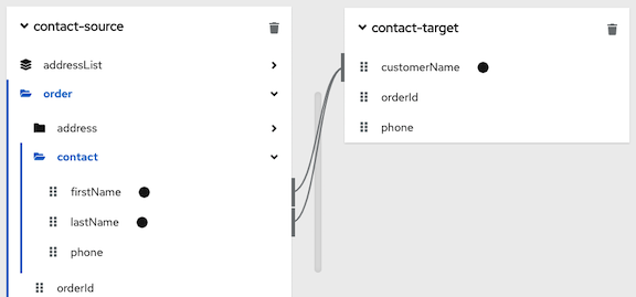
In the upper left, click
 to display the conditional expression input field.
In the expression field, the data mapper automatically displays the names of the source fields in the current mapping. For example:
In the expression input field, the order of the source fields is the order in which you selected them when you created the mapping. This is important because the default mapping behavior is that the data mapper concatenates the field values in this order to insert the result in the target field. In this example, to create this mapping,
lastNamewas selected first and thenfirstNamewas selected.Edit the expression input field to specify the conditional expression that you want the data mapper to apply to the mapping. Details about supported conditional expressions follow this procedure.
If you want to include a transformation in a conditional mapping, you must add the transformation to the conditional expression.
As you specify the expression, you can type
@and start to type the name of a field. The data mapper displays a list of the fields that match what you entered. Select the field that you want to specify in the expression.When you add a field name to the expression, the data mapper adds that field to the mapping. For example, consider this conditional expression:

During execution, if the data mapper determines that the
lastNamefield is empty, it maps only thefirstNamefield to the targetcustomerNamefield. If thelastNamefield contains a value, that is, it is not empty, the data mapper concatenates the values in the sourceorderIdandphonefields, and inserts the result in thecustomerNamefield. (This example shows how the logic works, but it is probably not a useful example because when there is a value in thelastNamefield, you most likely want the data mapper to simply perform the mapping and not map some other value into the target.)For this example, after you complete entering the expression, the data mapping is:
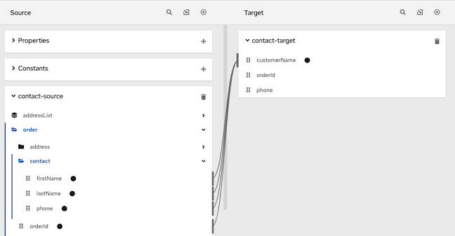
In the conditional expression, if you remove a field name that is in the mapping that the expression applies to, the data mapper removes that field from the mapping. In other words, every field name in the mapping must be in the conditional expression.
-
If mapping preview fields are not already visible, display them by clicking
.
- Type sample data in the source preview input field(s) to ensure that the target field or target fields get(s) the correct value.
- Edit the conditional expression as needed to obtain the desired result.
Supported functions in conditional expressions
ISEMPTY(source-field-name1 [+ source-field-name2])The result of the
ISEMPTY()function is a Boolean value. Specify at least one argument, which is the name of a source field in the mapping that you want to apply the condition to. When the specified source field is empty, theISEMPTY()function returns true.Optionally, add the + (concatenation) operator with an additional field, for example:
ISEMPTY(lastName + firstName)This expression evaluates to true if both source fields,
lastNameandfirstName, are empty.Often, the
ISEMPTY()function is the first argument in anIF()function.IF(boolean-expression, then, else)When
boolean-expressionevaluates to true, the data mapper returnsthen. Whenboolean-expressionevaluates to false, the data mapper returnselse. All three arguments are required. The last argument can be null, which means that nothing is mapped whenboolean-expressionevaluates to false.For example, consider the mapping that combines the
lastNameandfirstNamesource fields in the targetcustomerNamefield. You can specify this conditional expression:IF (ISEMPTY(lastName), firstName, lastName + ‘,’ + firstName )During execution, the data mapper evaluates the
lastNamefield.-
If the
lastNamefield is empty, that is,ISEMPTY(lastName)returns true, the data mapper inserts only thefirstNamevalue into the targetcustomerNamefield. If the
lastNamefield contains a value, that is,ISEMPTY(lastName)returns false, the data mapper maps thelastNamevalue, followed by a comma, followed by thefirstNamevalue into the targetcustomerNamefield.Now consider the behavior if the third argument in this expression is null:
IF (ISEMPTY(lastName), firstName, null )During execution, the data mapper evaluates the
lastNamefield.-
As in the previous example, if the
lastNamefield is empty, that is,ISEMPTY(lastName)returns true, the data mapper inserts only thefirstNamevalue into the targetcustomerNamefield. -
However, when the third argument is null, if the
lastNamefield contains a value, that is,ISEMPTY(lastName)returns false, the data mapper does not map anything into the targetcustomerNamefield.
-
If the
LT(x,y)or<(x,y)The data mapper evaluates
xandyand returns the lower value. Bothxandymust be numbers.TOLOWER(string)The data mapper converts the specified string to lowercase and returns it.
| Operator | Description |
|
| Add numeric values or concatenate string values. |
|
| Subtract a numeric value from another numeric value. |
|
| Multiply numeric values. |
|
| Divide numeric values. |
|
| Return true if both the left and right operands are true. Each operand must return a Boolean value. |
|
| Return true if the left operand is true, or if the right operand is true, or if both operands are true. Each operand must return a Boolean value. |
|
| Not |
|
| Return true if the left numeric operand is greater than the right numeric operand. |
|
< | Return true if the left numeric operand is less than the right numeric operand. |
|
| Return true if the left operand and the right operand are the same. |
7.14. Descriptions of available transformations
The following table describes the available transformations. The date and number types refer generically to any of the various forms of these concepts. That is, number includes, for example, integer, long, double. Date includes, for example, date, Time, ZonedDateTime.
| Transformation | Input Type | Output Type | Parameter (* = required) | Description |
|---|---|---|---|---|
|
| number | number | None | Return the absolute value of a number. |
|
| date | date |
| Add days to a date. The default is 0 days. |
|
| date | date |
| Add seconds to a date. The default is 0 seconds. |
|
| string | string | string | Append a string to the end of a string. The default is to append nothing. |
|
| string | string | None | Convert a phrase to a camelized string by removing whitespace, making the first word lowercase, and capitalizing the first letter of each subsequent word. |
|
| string | string | None | Capitalize the first character in a string. |
|
| number | number | None | Return the whole number ceiling of a number. |
|
| any | Boolean |
| Return true if a field contains the specified value. |
|
| number | number |
|
Convert a number that represents an area to another unit. For the |
|
| number | number |
|
Convert a number that represents a distance to another unit. For the |
|
| number | number |
|
Convert a number that represents mass to another unit. For the |
|
| number | number |
|
Convert a number that represents volume to another unit. For the |
|
| date | number | None | Return the day of the week (1 through 7) that corresponds to the date. |
|
| date | number | None | Return the day of the year (1 through 366) that corresponds to the date. |
|
| string | Boolean |
|
Return true if a string ends with the specified |
|
| any | Boolean |
|
Return true if the input field is equal to the specified |
|
| string | string | None | From a string that represents a file name, return the file extension without the dot. |
|
| number | number | None | Return the whole number floor of a number. |
|
| any | string |
|
In |
|
|
string | number |
|
Return the index of the character in the input string that is the parameter string’s first character. Return |
|
| any | Boolean | None | Return true if a field is null. |
|
|
string | number |
|
Return the index of the character in the input string that is the parameter string’s last character. Return |
|
| any | number | None |
Return the length of the field, or |
|
| string | string | None | Convert a string to lowercase. |
|
| string | string | None | Replace consecutive whitespace characters with a single space and trim leading and trailing whitespace from a string. |
|
| string | string |
|
Insert the character supplied in |
|
| string | string |
|
Insert the character supplied in |
|
| string | string |
|
Prefix |
|
| string | string |
|
In a string, replace all occurrences of the supplied matching string with the supplied |
|
| string | string |
|
In a string, replace the first occurrence of the specified |
|
| number | number | None | Return the rounded whole number of a number. |
|
| string | string | None | Replace each occurrence of whitespace, colon (:), underscore (_), plus (+), and equals (=) with a hyphen (-). |
|
| string | string | None | Replace each occurrence of whitespace, colon (:), hyphen (-), plus (+), and equals (=) with an underscore (_). |
|
| string | Boolean |
| Return true if a string starts with the specified string (including case). |
|
| string | string |
|
Retrieve a segment of a string from the specified inclusive |
|
| string | string |
|
Retrieve the segment of a string after the specified |
|
| string | string |
|
Retrieve a segment of a string before the supplied |
|
| string | string | None | Trim leading and trailing whitespace from a string. |
|
| string | string | None | Trim leading whitespace from a string. |
|
| string | string | None | Trim trailing whitespace from a string. |
|
| string | string | None | Convert a string to uppercase. |
7.15. Troubleshooting data mapping
The data mapper displays the largest possible set of source fields that can be provided by the previous integration step. However, not all connections provide data in each displayed source field. For example, a change to a third-party application might discontinue providing data in a particular field. As you create an integration, if you notice that data mapping is not behaving as you expect, ensure that the source field that you want to map contains the data that you expect.
A data shape change that affects a field that is already mapped might prevent the data mapper from loading a document. In this situation, when you try to edit a data mapper step that maps the affected field, the data mapper cannot display the source and target panels. Instead, it displays an error that indicates that it cannot load or cannot find the document. The error message looks like one of the following messages:
-
Data Mapper UI Initialization Error: Could not load document '-La_rwMD_ggphAW6nE9o': undefined undefined -
Could not find document for mapped field 'last_name' at URI atlas:json:-LaX4LMC1CfVJYp3JXM6
You must delete this data mapper step and replace it with a new data mapper step in which you map the updated fields.
While a data shape change to a mapped field always requires you to redo the mapping, you do not always need to delete and remove the data mapper step. For example, if an XML instance specifies an input data shape and you change the name of an element, the data mapper removes the mapping that was to/from the old field name. You just need to map to/from the field with the updated name.
It is possible to change the data shape for a mapped field in the following ways:
In an API provider integration, while editing a flow, you edit the OpenAPI document that defines the operation.
Changing the data shape of the operation response always prevents the data mapper from being able to load the document.
In a flow, you edit the input data type and/or the output data type for one of these kinds of connections:
- Amazon S3
- AMQ
- AMQP
- Dropbox
- FTP/SFTP
- HTTP/HTTPS
- Kafka
- IRC
- MQTT
Chapter 8. Managing integrations
A common set up is to have a Fuse Online development environment, a Fuse Online test environment, and a Fuse Online deployment environment. To facilitate this, Fuse Online provides the ability to export an integration from one Fuse Online environment and then import that integration into another Fuse Online environment. The information and procedures for managing integrations are the same in each kind of Fuse Online environment, unless specifically noted.
The following topics provide information to help you manage your integrations:
- Section 8.1, “About integration lifecycle handling”
- Section 8.2, “Putting integrations into and out of service”
- Section 8.3, “Logging information about integration execution”
- Section 8.4, “Monitoring integrations”
- Section 8.5, “Testing integrations”
- Section 8.6, “Tips for troubleshooting integration execution”
- Section 8.7, “Updating integrations”
- Section 8.8, “Adjusting the memory and CPU configuration attributes for an integration”
- Section 8.9, “Deleting integrations”
- Section 8.10, “Copying an integration to another environment”
8.1. About integration lifecycle handling
After you create and publish an integration, you might want to update what the integration does. You can edit a draft of the published integration and then replace the running version with the updated version. To facilitate this, for each integration, Fuse Online maintains multiple versions as well as each version’s state. An understanding of integration versions and states helps you to manage your integrations.
Description of integration versions
In each Fuse Online environment, each integration can have multiple versions. Support for multiple integration versions has several benefits:
- If you publish a version that does not work correctly, then you can return to running a correct version of the integration. To do that, you stop the incorrect version and start a version that runs the way you want it to.
- As requirements or tools change, you can incrementally update an integration. You do not need to create a new integration.
Fuse Online assigns a new version number each time it starts running a new version of an integration. For example, suppose you publish the Twitter to Salesforce sample integration. After it has been running, you update the integration to use a different account to connect to Twitter. You then publish the updated integration. Fuse Online stops the running version of the integration, and publishes the updated version of the integration with an incremented version number.
The initial integration that was running is version 1. The updated integration that is now running is version 2. If you edit version 2, for example to use a different account to connect to Salesforce, and you publish that version then it becomes version 3 of the integration.
There can be exactly one draft version of an integration. Fuse Online has a definition for the draft version of an integration but it has never run this version of the integration. The draft version of an integration does not have a number. When you edit an integration, you are updating the draft version of the integration.
In Fuse Online, you can see a list of the versions of an integration in the integration’s summary page. To view this page, in the left navigation panel, click Integrations. In the entry for the integration that you are interested in, click View.
Description of integration states
In Fuse Online, in the list of integration versions, each entry indicates the state of that version, which is one of the following:
| State | Description |
| Running | A Running version is executing; it is in service. Only one version of an integration can be running. That is, only one version at a time can be in the Running state. |
| Stopped | A Stopped version is not running. The draft version of an integration is in the Stopped state. Each integration that was running at one time and then stopped is in the Stopped state. If no version of this integration is in the Running state, then you can start a version that is stopped. |
| Pending | A pending version is in transition. Fuse Online is in the process of either starting this version of the integration or stopping this version of the integration, but the integration is not yet running or stopped. |
| Error |
An integration version that is in the Error state encountered an OpenShift error while being started or while running. The error suspended start-up or execution. If this happens, try starting an earlier integration version that ran correctly. Alternatively, contact technical support for help. To do that, in any Fuse Online page, in the upper right, click the
|
8.2. Putting integrations into and out of service
After you create an integration, you can save it as a draft or publish it to start running it. When you publish an integration, Fuse Online assembles the needed resources, builds the integration runtime, deploys the OpenShift pod that will run the integration, and then starts running the integration.
At any time, you can click a button to stop running the integration. When you want to start the integration again, Fuse Online already has what it needs so starting it takes less time than when you published it to run it for the first time.
The process of starting a version of an integration for the first time is referred to as publishing the integration. The following topics provide details:
8.2.1. About publishing integrations
To run a version of an integration for the first time, you publish it. Publishing an integration builds and deploys the integration runtime. The integration starts running. After publishing an integration, you can stop it and restart it. Exactly one version of an integration can be running at one time.
Alternatives for publishing
To run an integration for the first time, publish it by doing one of the following:
- At the end of the procedure in which you create or edit the integration, in the upper right, click Publish.
Publish the draft version of an integration:
- In the left Fuse Online panel, click Integrations.
-
In the list of integrations, to the right of the draft entry, click
 and select Publish.
About the publication progress
Fuse Online displays the progress of the publication process, which has several stages:
- Assembling creates pod resources needed to build the integration.
- Building gets the integration ready to deploy.
- Deploying waits for deployment of the pod that will run the integration.
- Starting waits for the pod to start running the integration.
- Deployed indicates that the integration is running.
During start-up, you can click View Logs to display OpenShift logs that provide start-up information.
Integration status after publication
When publishing the integration is complete, the Running status appears next to the integration name. The pod is running the integration.
8.2.2. Stopping integrations
Each integration can have exactly one version that is running. A running version is in the Running state. At any time, you can stop running an integration.
Prerequisite
The integration that you want to stop is in the Running state.
Procedure
- In the left Fuse Online panel, click Integrations.
- In the list of integrations, identify the entry for the integration that you want to stop running. The entry shows that this integration is Running.
-
On the far right of this integration’s entry, click
and select Stop.
Result
Fuse Online stops running the integration. Stopping and then Stopped appears in the integration’s entry in the list of integrations.
8.2.3. Starting integrations
The first time that you start an integration, the process is referred to as publishing the integration because Fuse Online has to build the integration runtime before it can run the integration. At any time, you can stop running an integration and then start it again.
Prerequisite
The integration that you want to start is in the Stopped state.
Procedure
- In the left navigation panel, click Integrations.
-
In the list of integrations, on the right of the entry for the integration that you want to start, click
.
- Select Start.
Result
Fuse Online displays Starting as the status of that integration version, and then Running when the integration is running again.
8.2.4. Restarting older integration versions
You might publish an integration that does not work the way you want it to. In this situation, you can stop the incorrect version and replace it with a version that you published previously and that runs correctly.
Prerequisites
- A version of the integration is running but you want to stop it.
- You have another version of the integration and you want to run that one.
Procedure
- In the left panel, click Integrations to display a list of the the integrations in this environment.
- Click the entry for the integration for which you want to publish an older version. Fuse Online displays a list of the versions of the integration.
-
In the entry for the version that is running, at the far right, click
and select Stop.
- Click OK to confirm that you want to stop running this version.
- Wait for Stopped to appear to the right of the integration name near the top of the page.
To publish the older version as is, skip to the next step. Or, before you publish the older version, you can update it:
-
In the entry for the integration version that you want to update, at the far right, click
and select Replace Draft.
- Update the integration as needed.
- When updates are complete, in the upper right, click Publish, and then click Publish to confirm. This takes the place of the next two steps.
-
In the entry for the integration version that you want to update, at the far right, click
-
To publish the older version as is, in the entry for the integration version that you want to start running again, at the far right, click
and select Start.
- Click Start to confirm that you want to start this version of the integration.
Result
Fuse Online starts the integration, which takes a few minutes. When the integration is running, then Running version n appears to the right of the integration’s name.
8.3. Logging information about integration execution
For each execution of an integration, for each step in a flow, Fuse Online provides the following activity information:
- The date and time that the step was executed
- How long it took to execute the step
- Whether execution was successful
- The error message if execution was not successful
To view this information in Fuse Online, display the integration’s summary and then click the Activity tab.
To obtain further details about integration execution, you can log information about the messages that an integration processes by adding a log step to an integration flow. For each message that an integration receives, a log step can provide one or more of the following:
- The message’s context, which provides metadata about the message, including the message’s header.
- The message’s body, which provides the content of the message.
- Text that you specify either explicitly or through evaluation of an Apache Camel Simple language expression.
The Log connection that was available in previous releases is no longer available to be added to integrations. Add a log step instead of a log connection.
Prerequisites
- You are creating or editing a flow and Fuse Online is prompting you to add to the integration. Or, Fuse Online is prompting you to choose a finish connection.
Procedure
- In the flow visualization, click the plus sign where you want to add a log step. Skip this step if Fuse Online is prompting you to choose a finish connection.
- Click Log.
On the Configure Log Step page, select the content that you want to log. If you select Custom Text, then in the text input field, enter one of the following:
- The text that you want to log
- A Camel Simple language expression
If you enter an expression, Fuse Online resolves the expression and logs the resulting text.
- When log step configuration is complete, click Next to add the step to the flow.
Next step
When the flow is complete, publish the integration to start seeing output from the new log step.
Additional resources
After a flow that has a log step has been executed, output from the log step appears in the integration’s Activity tab. See Viewing integration activity information.
8.4. Monitoring integrations
Fuse Online provides various ways for you to monitor the execution of your integrations. See:
8.4.1. Viewing integration history
Fuse Online maintains each version of an integration. You can always view a list of the versions of each integration.
Procedure
- In the left panel, click Integrations to display a list of the integrations in your environment.
- At the right of the entry for the integration whose versions you want to see, click View.
Result
In the page that appears, the History section lists the versions of the integration. The
 icon identifies the current version, which is the most recently, successfully running version. For each version, you can also see the date on which it was last started.
To edit, start, or stop a particular version, click the
to the right of the version’s entry. Select the operation that you want to perform.
8.4.2. Viewing information about an integration’s activity
Fuse Online provides activity information for each execution of an integration. This information is part of the integration’s log. For each step in a flow, Fuse Online provides:
- The date and time that the step was executed
- How long it took to execute the step
- Whether execution was successful
- The error message if execution was not successful
At any time, you can view this information.
Prerequisites
- There is or was a running integration for which you want to view activity information.
- This integration has been executed at least once.
Procedure
- In the left panel, click Integrations.
- At the right of the entry for the integration for which you want to view activity information, click View.
- In the integration’s summary page, click the Activity tab.
- Optionally, enter date and/or keyword filters to limit the executions listed.
- Click the integration execution for which you want to view activity information.
For an API Provider integration or a webhook step, the information in the integration’s Activity tab reflects the communication between the Fuse Online integration and the client that invokes it. Errors generated by HTTP or REST requests are not visible in the integration’s Activity log. If you want to view or test the errors generated by HTTP or REST requests, when you configure the API Provider or the webhook step, check the Include error message in the return body option (checked by default). Then, you can verify whether the error message is included in the response by checking the HTTP or REST header in the response to the caller. You can also check the integration pod’s log file for INFO messages.
Additional resources
- To obtain additional information between any two steps, you can add a log step to the integration. A log step provides information about each message it receives and can provide custom text that you specify. If you add a log step, then it appears as one of the integration’s steps when you expand the integration execution that you want to view activity information for. You view Fuse Online information for a log step in the same way that you view Fuse Online information for any other step. See Logging information about integration execution.
8.4.3. Viewing metrics for a particular integration
Fuse Online provides the following metrics for each integration:
- Total Errors indicates the number of runtime errors that all executions of this integration encountered during the past 30 days.
- Last Processed displays the most recent date and time that this integration processed a message. The message might have been successfully processed or there might have been an error.
- Total Messages is the number of messages that all executions of this integration processed in the last 30 days. This includes message failures.
- Uptime indicates when this integration started running and how long it has been running without an error.
Prerequisite
The integration that you want to view metrics for is running or has been running.
Procedure
- In the left panel, click Integrations.
- At the right of the entry for the integration for which you want to view metrics, click View.
- In the integration’s summary page, click Metrics.
8.4.4. Viewing metrics for a Fuse Online environment
Metrics for your Fuse Online environment appear on the Fuse Online home page.
Procedure
In the left panel, click Home.
Results
Fuse Online updates the following metrics every 5 seconds:
- The number of integrations that are defined in this environment as well as the number of integrations that are running, the number of integrations that are stopped, and the number of integrations that are pending. Fuse Online is either stopping or starting pending integrations. A red cross indicates any integrations that were running but that encountered an error that suspended execution.
- The number of connections that are defined in this environment.
- Total number of messages that have been processed by integrations in this environment in the last 30 days. This includes messages that were processed by integrations that might no longer be running or that might have been deleted from this environment.
- Uptime indicates how long there has been at least one integration that is running. The date and time when uptime started appears as well.
8.5. Testing integrations
After you create an integration and it is running correctly in a Fuse Online development environment, you might want to run it in a different Fuse Online environment to test it.
Prerequisite
- You have a Fuse Online development environment and a Fuse Online test environment.
- You have an integration that is running correctly in your Fuse Online development environment.
Procedure
- Learn about copying an integration to another environment.
- Export the integration from the development environment. See Exporting an integration.
- Import the integration into the test environment. See Importing an integration.
8.6. Tips for troubleshooting integration execution
If an integration stops working, check its activity and history details. See Viewing integration activity information and Viewing integration history.
Insufficient memory for integrations
If the Fuse Online Operator logs shows that an integration’s status is not ready or if an integration’s pod events report insufficient memory, you might need to edit the integration’s deployment configuration as described in Adjusting the memory and CPU configuration attributes for an integration.
Connection to an application that uses OAuth
For a connection to an application that uses OAuth, you might see an error message that indicates that the access token for the application has expired. Sometimes, you might get a less explicit 403 - Access denied message. The information in the message depends on the application that the integration is connecting to. In this situation, try reconnecting to the application and then republishing the integration:
- In the left panel, click Integrations.
- In the list of integrations, at the right of the entry for the integration that stopped running, click View.
In the integration’s summary page, in the flow visualization, click the icon for the application that you want to reconnect to.
If this is an API provider integration, then in the integration’s summary page, click its flow icon to display the operations list. Then click the operation whose path contains the connection that is failing and then click the failing connection in the operation’s path visualization.
- In the connection’s details page, click Reconnect.
Respond to that application’s OAuth workflow prompts.
Fuse Online displays a message to indicate that its access to that application has been authorized. For some applications, this takes a few seconds but it can take longer for other applications.
- After reconnecting to the application, start the integration.
If reconnection is not successful, try this:
- Re-register Fuse Online as a client of the application. See General procedure for obtaining authorization.
- Create a new connection.
Edit each integration that was using the old connection:
- Remove the old connection.
- Replace it with the new connection.
- Publish each updated integration.
8.7. Updating integrations
After you create an integration, you might need to update it to add, edit or remove a step.
Prerequisite
In your Fuse Online environment, there is a version of the integration that you want to update.
Procedure
- In the left Fuse Online panel, click Integrations.
- In the list of integrations, click View for the integration that you want to update.
On the integration’s summary page, in the upper right corner, click Edit Integration.
If this is a simple integration, Fuse Online displays the integration’s flow. If this is an API provider integration, Fuse Online displays the operations list. To update the flow for a particular operation, click Edit flow on the right of that operation to display its flow.
Update the flow as needed:
- To add a step, in the flow visualization, click the plus sign that is where you want to add the step. Then click the card that represents the step that you want to add.
-
To delete a step, in the flow visualization, click
on the step that you want to delete.
- To change the configuration of a step, in the flow visualization, click Configure on the step that you want to update. In the configuration page, update the parameter settings as needed.
8.8. Adjusting the memory and CPU configuration attributes for an integration
You can specify custom values for a specific integration’s CPU and memory by editing the integration’s deployment configuration object. You might want to adjust the memory and CPU configuration attributes for an integration, for example, if the integration requires more memory than its default allocation.
Prerequisite
-
The Red Hat OpenShift
occlient tool is installed and it is connected to the OCP cluster in which Fuse Online is installed. -
A user with cluster administration permissions gave you
adminpermission for the project that contains the integration that you want to configure.
Procedure
Log in to OpenShift with an account that has
adminpermission for the OpenShift project that contains the Fuse Online integration. For example:oc login -u admin -p adminSwitch to the project that contains the Fuse Online integration. For example:
oc project my-fuse-online-projectEdit the integration’s deployment configuration object:
Enter the following command, which typically opens the resource in an editor:
oc edit deploymentconfig <i-integration-name>For example, if the integration’s name is
my-integration, type this command:oc edit deploymentconfig i-my-integrationEdit the configuration by setting
spec.containers.resourcesto specify values for CPU and memory as shown in the following example:spec: containers: resources: limits: cpu: 350m requests: memory: 350Mi- Save the configuration.
Results
After you save your changes, the integration’s pod restarts and the new pod runs with the new values. For example, if you run the oc describe <intergration-pod-name> command (where you replace <intergration-pod-name> with the name of the integration pod, for example i-my-integration), the command returns the new values, such as:
    resources:
      limits:
        cpu: 350m
      requests:
        cpu: 350m
        memory: 350Mi
These values persist even after you publish a new version of the integration.
Additional resources
To set the default value for all integration’s CPU and memory attributes, an OpenShift cluster administrator can update the Fuse Online custom resource as described in Descriptions of custom resource attributes that configure Fuse Online in {NameOfFuseOnlineOnOCP}.
8.9. Deleting integrations
After you delete an integration, Fuse Online still has the history of that integration. If you import a version of the deleted integration, then Fuse Online associates the history of the deleted integration with the imported integration.
Procedure
- In the left Fuse Online panel, click Integrations.
-
In the list of integrations, at the right of the entry for the integration that you want to delete, click
and select Delete.
- In the popup, click OK to confirm that you want to delete the integration.
8.10. Copying an integration to another environment
To run integrations across development, staging and production environments, you can export and import integrations. The environments can all be on a single OpenShift cluster, or they can be spread out across multiple OpenShift clusters.
The procedures described here instruct you to export and import integrations in the Fuse Online console.
If you are running Fuse Online on OpenShift Container Platform on-site, you might have Continuous Integration/Continuous Deployment (CI/CD) pipelines that need to export and import certain integrations. For information about doing that, see Using external tools to export/import integrations for CI/CD.
See the following topics:
8.10.1. About copying integrations
Each Fuse Online installation is an environment from which you can export an integration. Exporting an integration downloads a zip file that contains the information needed to recreate the integration in a different Fuse Online environment.
In an environment, each integration can have only one Draft version.
The result of importing an integration depends on:
- Whether the integration was previously imported
- Whether a connection that the integration uses was previously imported
Fuse Online uses an internal identifier for each integration and each connection to determine whether it already exists in the environment that it is being imported into. If you change the name of an integration or connection, Fuse Online recognizes it as the same integration or connection, which just has a different name.
The following table describes the possible results of importing an integration:
| In the importing environment: | What the import operation does: |
|---|---|
| The integration has not been previously imported. | Creates the integration. The integration is in the Draft state. |
| The integration has been previously imported. | Fuse Online updates the integration. The updated integration is in the Draft state. If there was a Draft version of this integration, it is lost. |
| The imported integration uses a connection that did not exist in the environment before the import operation. | Fuse Online creates a connection that has the same settings except for secrets. You must review each new connection. If a connection is not completely configured for its new environment then you must add the missing settings. For example, you might need to obtain secret settings by registering this Fuse Online environment as a client of the application that this connection accesses. |
8.10.2. Exporting integrations
When Fuse Online exports an integration it downloads a zip file to your local Downloads folder. This zip file contains the information needed to recreate the integration in a different Fuse Online environment.
Exporting an integration is also a way to have a backup of the integration. However, Fuse Online maintains the versions of an integration so exporting an integration is not required for having a backup copy.
Procedure
- In the left panel of Fuse Online, click Integrations.
- In the list of integrations, identify the entry for the integration that you want to export.
-
At the right of the entry, click
and select Export.
Next step
To import the integration into another Fuse Online environment, open that environment and import the exported zip file.
8.10.3. Importing integrations
In a Fuse Online environment, you can import an integration that was exported from another Fuse Online environment. Exporting an integration downloads the zip file that you upload to import the integration.
Prerequisites
- You have a zip file that contains an integration that was exported from another Fuse Online environment.
Procedure
- Open the Fuse Online environment that you want to import the integration into.
- In the left panel, click Integrations.
- In the upper right, click Import.
Drag and drop one or more exported integration zip files, or navigate to a zip file that contains an exported integration and select it.
Fuse Online imports the file(s) and display a message when importing is successful.
- In the left panel, click Integrations.
- In the list of integrations, on the entry for the integration that you just imported, click View.
- In the integration summary, if there is a notification that configuration is required, in the upper right, click Edit integration.
For each connection that requires configuration:
- Click its Configure button to display its details.
- Enter or change connection details as needed. It is possible that every field on this page is correct and that only security configuration is required.
- Click Next.
In the left panel, click Settings.
The Settings page displays entries for applications that use the OAuth protocol.
For each connection that requires configuration and that accesses an application that uses the OAuth protocol, register your Fuse Online environment with the application. The steps vary for each application. See the appropriate topic:
- In the left panel, click Connections and confirm that there are no longer any connections that require configuration.
- In the left panel, click Integrations. In the list of integrations, imported integrations have a green triangle in the upper left corner of their entries.
-
In the list of integrations, at the right of the entry for the integration that you imported, click
and select Edit.
- In the upper right, click Save or, if you want to start running the imported integration, click Publish. Regardless of whether you save the integration as a draft or you publish the integration, Fuse Online updates the integration to use the updated connections.
Chapter 9. Customizing Fuse Online
Fuse Online provides many connectors that you can use to connect to common applications and services. There are also a number of built-in steps for processing data in common ways. However, if Fuse Online does not provide a feature that you need, talk with a developer about your requirements. An experienced developer can help you customize integrations by providing any of the following:
An OpenAPI document that Fuse Online can use to create a connector for a REST API client.
You upload this schema to Fuse Online and Fuse Online creates a connector according to the schema. You then use the connector to create a connection that you can add to an integration. For example, many retail web sites provide a REST API client interface that a developer can capture in an OpenAPI document.
An OpenAPI document that defines a REST API service.
You upload this schema to Fuse Online. Fuse Online makes the API service available and provides the URL for API calls. This lets you trigger integration execution with an API call.
A WSDL file that Fuse Online can use to create a connector for a SOAP client.
Note: This is a Technology Preview feature.
A
JARfile that implements a Fuse Online extension. An extension can be any one of the following:- One or more steps that operate on integration data between connections
- A connector for an application or service
A library resource such as a JDBC driver for a proprietary SQL database
You upload this
JARfile to Fuse Online and Fuse Online makes the custom feature provided by the extension available.
See the following topics for details:
9.1. Developing REST API client connectors
Fuse Online can create connectors for Representational State Transfer Application Programming Interfaces (REST APIs) that support Hypertext Transfer Protocol (HTTP). To do this, Fuse Online requires a valid OpenAPI 3 (or 2) document that describes a REST API that you want to connect to. If the API service provider does not make an OpenAPI document available then an experienced developer must create the OpenAPI document.
The following topics provide information and instructions for developing REST API connectors:
9.1.1. Requirements for REST API client connectors
After you upload an OpenAPI schema to Fuse Online, a connector to the REST API becomes available. You can select the connector to create a REST API client connection. You can then create a new integration and add the REST API client connection, or you can edit an existing integration to add the REST API client connection.
Fuse Online connectors support OAuth 2.0, HTTP basic authorization, and API keys. If access to the REST API requires Transport Layer Security (TLS) then the API needs to use a valid certificate that is issued by a recognized Certificate Authority (CA).
A REST API that uses OAuth must have an authorization URL that takes a client callback URL as input. After Fuse Online creates the connector and before you use the connector to create a connection, you must visit that URL to register your Fuse Online environment as a client of the REST API. This authorizes your Fuse Online environment to access the REST API. As part of registration, you provide the Fuse Online callback URL. The details for doing this are described in Connecting Fuse Online to Applications and Services, Registering Fuse Online as a REST API client.
For a REST API that uses OAuth, Fuse Online supports only the Authorization Code grant flow for obtaining authorization. In the OpenAPI document that you upload to create the connector, in the OAuth securityDefinitions object, you must set the flow attribute to accessCode, for example:
securityDefinitions:
  OauthSecurity:
    type: oauth2
    flow: accessCode
    authorizationUrl: 'https://oauth.simple.api/authorization'
    tokenUrl: 'https://oauth.simple.api/token'
You must not set flow to implicit, password, or application.
The OpenAPI schema for a REST API client connector cannot have cyclic schema references. For example, a JSON schema that specifies a request or response body cannot reference itself as a whole nor reference any part of itself through any number of intermediate schemas.
Fuse Online cannot create connectors for REST APIs that support the HTTP 2.0 protocol.
9.1.2. Guidelines for OpenAPI schemas for REST API client connectors
When Fuse Online creates a REST API client connector, it maps each resource operation in the OpenAPI document to a connection action. The action name and action description come from documentation in the OpenAPI document.
The more detail that the OpenAPI document provides, the more support Fuse Online can offer when connecting to the API. For example, the API definition is not required to declare data types for requests and responses. Without type declarations, Fuse Online defines the corresponding connection action as typeless. However, in an integration, you cannot add a data mapping step immediately before or immediately after an API connection that performs a typeless action.
One remedy for this is to add more information to the OpenAPI document. Identify the OpenAPI resource operations that will map to the actions you want the API connection to perform. In the OpenAPI document, ensure that there is a YAML or JSON schema that specifies each operation’s request and response types.
After you upload the schema, Fuse Online gives you an opportunity to review and edit it in API Designer, which is a visual editor for designing APIs based on the OpenAPI document. You can add more detail, save your updates, and Fuse Online creates an API client connector that incorporates your updates. After Fuse Online creates the client connector, you can no longer edit the OpenAPI document. To implement a change, you must create a new client connector.
If the OpenAPI document for the API declares support for application/json content type and also application/xml content type then the connector uses the JSON format. If the OpenAPI document specifies consumes or produces parameters that define both application/json and application/xml, then the connector uses the JSON format.
9.1.3. Provide client credentials in parameters
When Fuse Online tries to obtain authorization to access an OAuth2 application, it uses HTTP basic authentication to provide client credentials. If you need to, you can change this default behavior so that Fuse Online passes client credentials to the provider as parameters instead of using HTTP basic authentication. This affects the use of the tokenUrl endpoint that is used to obtain an OAuth access token.
This is a Technology Preview feature.
To specify that Fuse Online should pass client credentials as parameters, in the securityDefinitions section of the OpenAPI document, add the x-authorize-using-parameters vendor extension with a setting of true. In the example below, the last line specifies x-authorize-using-parameters:
securityDefinitions:
  concur_oauth2:
    type: 'oauth2'
    flow: 'accessCode'
    authorizationUrl: 'https://example.com/oauth/authorize'
    tokenUrl: 'https://example.com/oauth/token'
    scopes:
      LIST: Access List API
    x-authorize-using-parameters: true
The setting of the x-authorize-using-parameters vendor extension is true or false:
-
trueindicates that client credentials are in parameters. -
false, the default, indicates that Fuse Online uses HTTP basic authentication to provide client credentials.
9.1.4. Automatically refresh access tokens
If an access token has an expiration date, then Fuse Online integrations that use that token to connect to an application stop running successfully when the token expires. To obtain a new access token, you must either reconnect to the application or re-register with the application.
If you need to, you can change this default behavior so that Fuse Online automatically requests a new access token in the following situations:
- When the expiration date has been reached.
- When HTTP response status codes that you specify are received.
This is a Technology Preview feature.
To specify that Fuse Online should automatically try to obtain a new access token in the situations described, in the securityDefinitions section of the OpenAPI document, add the x-refresh-token-retry-statuses vendor extension. The setting of this extension is a comma separated list that specifies HTTP response status codes. When an access token’s expiration date is reached or when Fuse Online receives a message from an OAuth2 provider and the message has one of these response status codes, then Fuse Online automatically tries to obtain a new access token. In the example below, the last line specifies x-refresh-token-retry-statuses:
securityDefinitions:
  concur_oauth2:
    type: 'oauth2'
    flow: 'accessCode'
    authorizationUrl: 'https://example.com/oauth/authorize'
    tokenUrl: 'https://example.com/oauth/token'
    scopes:
      LIST: Access List API
x-refresh-token-retry-statuses: 401,402,403Sometimes, an API operation fails and a side effect of that failure is that the access token is refreshed. In this situation, even when obtaining a new access token is successful, the API operation still fails. In other words, Fuse Online does not retry the failed API operation after it receives the new access token.
9.2. Adding and managing API client connectors
Fuse Online can create these API client connectors:
- A REST API client connector from an OpenAPI document. For information about the content of the OpenAPI document, see Developing REST API client connectors.
A SOAP API client connector from a WSDL file.
ImportantThe SOAP API client connector is a Technology Preview feature only. Technology Preview features are not supported with Red Hat production service level agreements (SLAs) and might not be functionally complete. Red Hat does not recommend using them in production.These features provide early access to upcoming product features, enabling customers to test functionality and provide feedback during the development process.For more information about the support scope of Red Hat Technology Preview features, see https://access.redhat.com/support/offerings/techpreview/
The following topics provide information and instructions for adding and managing REST API client connectors:
After you create an API client connector, for details about using that connector, see Connecting Fuse Online to Applications and Services, Connecting to API clients.
9.2.1. Creating REST API client connectors
Upload an OpenAPI document to enable Fuse Online to create a REST API client connector.
Prerequisite
You have an OpenAPI document for the connector that you want Fuse Online to create.
Procedure
- In the Fuse Online navigation panel, click Customizations > API Client Connectors. Any API client connectors that are already available are listed here.
- Click Create API Connector.
On the Create API Connector page, do one of the following:
- Click in the dotted-line box and select the OpenAPI file that you want to upload.
- Select Use a URL and paste the URL for the OpenAPI document in the input field.
Click Next. If there is invalid or missing content, Fuse Online displays information about what needs to be corrected. Select a different OpenAPI file to upload or click Cancel, revise the OpenAPI file, and upload the updated file.
If the schema is valid, Fuse Online displays a summary of the operations that the connector provides. This might include errors and warnings about the operation definitions.
If you are satisfied with the summary, click Next.
Or, to revise the OpenAPI document, click Review/Edit to open the API Designer editor. Update the schema as needed. For details about using the API editor, see Design and develop an API definition with API Designer. When you are done, Save your changes to incorporate your updates into the new API client connector. Then click Next to continue creating the API client connector.
Sometimes, if you provide a URL for the OpenAPI document, Fuse Online can upload it but cannot open it for editing. Typically, this is caused by settings on the file’s host. To open the schema for editing, Fuse Online requires that the file host has:
-
An
httpsURL. (AnhttpURL does not work.) - Enabled CORS.
-
An
Indicate the API’s security requirements. Fuse Online reads the OpenAPI definition to determine the information needed to configure the connector to meet the API’s security requirements. Fuse Online can display any of the following:
- No Security
- HTTP Basic Authorization — If the API service uses HTTP basic authorization, select this checkbox. Later, when you use this connector to create a connection, Fuse Online prompts you to enter a user name and password.
OAuth 2.0 — Fuse Online prompts you to enter:
- Authorization URL is the location for registering Fuse Online as a client of the API. Registration authorizes Fuse Online to access the API. See Connecting Fuse Online to Applications and Services, Registering Fuse Online as a REST API client. The OpenAPI document or other documentation for the API should specify this URL. If it does not then you must contact the service provider to obtain this URL.
- Access Token URL is required for OAuth authorization. Again, the OpenAPI document or other documentation for the API should provide this URL. If it does not then you must contact the service provider.
- API Key — If the API service requires an API key, Fuse Online prompts for any information that it needs to create the connector. Prompts are based on the OpenAPI definition. For example, you might need to indicate if the API key is in message headers or in query parameters. If the OpenAPI definition specifies API key security, as well as another security type, select the checkbox to indicate that you want to use API key security in connections based on this connector. Later, when you use this connector to create a connection, Fuse Online prompts you to enter the value of an API key.
Click Next. Fuse Online displays the connector’s name, description, host, and base URL as indicated by the OpenAPI document. For connections that you create from this connector,
-
Fuse Online concatenates the host and base URL values to define the endpoint for the connection. For example, if the host is
https://example.comand the base URL is/api/v1then the connection endpoint ishttps://example.com/api/v1. - Fuse Online applies the OpenAPI document to data mapping steps. If the OpenAPI document supports more than one schema then Fuse Online uses the TLS (HTTPS) schema.
-
Fuse Online concatenates the host and base URL values to define the endpoint for the connection. For example, if the host is
- Review the connector details and optionally upload an icon for the connector. If you do not upload an icon, Fuse Online generates one. You can upload an icon at a later time. When Fuse Online displays the flow of an integration, it displays a connector’s icon to represent connections that are created from that connector.
To override a value obtained from the OpenAPI file, edit the field value that you want to change.
ImportantAfter Fuse Online creates a connector, you cannot change it. To effect a change, you need to upload an updated OpenAPI document so that Fuse Online can create a new connector or you can upload the same schema and then edit it in the API editor. You then continue the process for creating a new API client connector.
- When you are satisfied with the connector details, click Save. Fuse Online displays the new connector in the list of API Client Connectors.
Next step
For details about using your new API connector, see Connecting Fuse Online to Applications and Services, Connecting to API clients.
9.2.2. Creating SOAP API client connectors
Upload a WSDL file to enable Fuse Online to create a SOAP API client connector.
The SOAP API client connector is a Technology Preview feature only. Technology Preview features are not supported with Red Hat production service level agreements (SLAs) and might not be functionally complete. Red Hat does not recommend using them in production.These features provide early access to upcoming product features, enabling customers to test functionality and provide feedback during the development process.For more information about the support scope of Red Hat Technology Preview features, see https://access.redhat.com/support/offerings/techpreview/
Prerequisite
You have a WSDL file for the SOAP client connector that you want Fuse Online to create.
Note: For this release, the WSDL file’s extension (.wsdl) must be lowercase. If the file extension is uppercase (.WSDL) you must rename the file to have a lowercase extension before you import it into Fuse Online.
Procedure
- In the Fuse Online navigation panel, click Customizations > API Client Connectors. Any API client connectors that are already available are listed here.
- Click Create API Connector.
On the Create API Connector page, do one of the following:
-
Click in the dotted-line box and select the WSDL (
.wsdl) file that you want to upload. -
Select Use a URL and paste the URL for the WSDL (
.wsdl) file in the input field.
-
Click in the dotted-line box and select the WSDL (
- Click Next.
- On the Specify service and port page, verify the service and port.
- Click Next. If there is invalid or missing content, Fuse Online displays information about what needs to be corrected. Select a different WSDL file to upload or click Cancel, revise the WSDL file, and then upload the updated file. If the schema is valid, Fuse Online displays a summary of the API definition (name and description) and a list of imported elements, such as the number of operations.
Click Next.
Note: For this release, the security requirements on this page are inactive. Instead, you can define the security options when you create a connection from the connector, as described in Connecting Fuse Online to Applications and Services, Creating a SOAP API client connection.
Click Next. Fuse Online displays the connector’s name, description, and WSDL endpoint address.
Optionally, upload an icon for the connector. You can also upload an icon at a later time.
Note: For this release, If you do not upload an icon, Fuse Online does not generate one for you.
When Fuse Online displays the flow of an integration, it displays a connector’s icon to represent connections that are created from that connector.
- For Name, enter your choice of a name that helps you distinguish this connection from any other connections.
- Optionally, for Description, enter information that is helpful to know about this connection.
Review the connector details and to override a value obtained from the WSDL file, edit the field value that you want to change.
ImportantAfter Fuse Online creates a connector, you cannot change it. To effect a change, you need to upload an updated OpenAPI document so that Fuse Online can create a new connector or you can upload the same schema and then edit it in the API editor. You then continue the process for creating a new API client connector.
- When you are satisfied with the connector details, click Save. Fuse Online displays the new connector in the list of API Client Connectors.
Next step
For details about using your new API connector, see Connecting Fuse Online to Applications and Services, Connecting to API clients.
9.2.3. Updating API client connectors by creating new ones
When there is an update to an OpenAPI document or WSDL file from which you created an API client connector, and you want your API client connector to use those updates, you must create a new API client connector. You cannot directly update an API client connector. After you create the new API client connector, you use it to create a new connection and then you edit each integration that uses a connection that was created from the out-of-date connector.
Prerequisites
Be prepared to do one of the following:
For a REST API client connector:
- Upload the updated OpenAPI document.
- Upload the out-of-date schema again and update it in API Designer.
- For a SOAP API client connector, upload the updated WSDL file.
Procedure
Create a new API client connector based on the updated OpenAPI document or WSDL file. To easily distinguish between the old connector and the new connector, you might want to specify a version number in the connector name or the connector description.
- Create a new connection from the new connector. Again, you want to be able to easily distinguish between connections created from the old connector and connections created from the new connector. A version number in the connection name or connection description is helpful.
- Edit each integration that uses a connection that was created from the old connector by removing the old connection and adding the new connection.
- Publish each updated integration.
- Recommended, but not required: delete the old connector and the old connections.
9.2.4. Deleting API client connectors
You cannot delete a connector when there is a connection that was created from that connector and this connection is being used in an integration. After you delete an API client connector, you cannot use a connection that was created from that connector.
Procedure
- In the left panel, click Customizations > API Client Connectors.
- To the right of the name of the connector that you want to delete, click Delete.
- In the confirmation popup, if you sure that you want to delete the connector, click Delete.
9.3. Developing Fuse Online extensions
If Fuse Online does not provide a feature that is needed to create an integration, then an expert developer can code an extension that provides the needed behavior. The Syndesis extension repository, https://github.com/syndesisio/syndesis-extensions, contains examples of extensions.
A business integrator shares requirements with a developer who codes the extension. The developer provides a .jar file that contains the extension. The business integrator uploads the .jar file in Fuse Online to make the custom connector, custom step(s), or library resource available for use in Fuse Online.
The Fuse Tooling plugin to Red Hat Developer Studio provides a wizard that helps you develop a step extension or a connector extension. It is a matter of personal preference whether you choose to develop a step extension or a connector extension in Developer Studio or in some other IDE. For information about using the Developer Studio plugin, see Developing extensions for Fuse Online integrations.
In this document, the following topics outline the procedure, describe the requirements, and provide additional examples for developing extensions in an IDE that you choose.
- Section 9.3.1, “General procedure for developing extensions”
- Section 9.3.2, “Description of the kinds of extensions”
- Section 9.3.3, “Overview of extension content and structure”
- Section 9.3.4, “Requirements in an extension definition JSON file”
- Section 9.3.5, “Descriptions of user interface properties”
- Section 9.3.6, “Description of Maven plugin that supports extensions”
- Section 9.3.7, “How to specify data shapes in extensions”
- Section 9.3.8, “Examples of developing step extensions”
- Section 9.3.9, “Example of developing a connector extension”
- Section 9.3.10, “How to develop library extensions”
- Section 9.3.11, “Creating JDBC driver library extensions”
9.3.1. General procedure for developing extensions
Before you start to develop an extension, become familiar with the tasks that you will need to accomplish.
Prerequisites
An integration pod runs in a Java process with a flat classpath. To avoid version clashes, make sure that the dependencies that an extension uses are aligned with the imported bill of materials (BOM) from all of these sources:
-
org.springframework.boot:spring-boot-dependencies:$SPRING_BOOT_VERSION -
org.apache.camel:camel-spring-boot-dependencies:$CAMEL_VERSION -
io.syndesis.integration:integration-bom:$SYNDESIS_VERSION
If there are additional dependencies that are not part of the imported BOMs, you must:
-
Package them in the extension JAR file that is in the
libdirectory. -
Omit them from the
dependenciesproperty of the extension’s JSON descriptor file.
Procedure
- Obtain an understanding of what the extended feature must do. Talk to your business colleague to understand the feature requirements.
- Determine whether you need to develop a step extension, a connector extension, or a library extension.
- Set up the Maven project in which to develop the extension.
If you are developing a step extension:
-
Decide whether to implement it as a Camel route or implement it by using the Syndesis
StepAPI. Information for the Syndesis API is at http://javadoc.io/doc/io.syndesis.extension/extension-api. -
If you choose to implement the extension as a Camel route, decide whether to implement XML fragments, a
RouteBuilderclass, or a bean. -
In your Maven project, specify the required metadata, such as the
schemaVersion, extensionname,extensionId, and so on.
-
Decide whether to implement it as a Camel route or implement it by using the Syndesis
- Code the classes that implement the feature.
-
Add dependencies to the project’s
pom.xmlfile. For connector and library extensions, and for step extensions that you implement in XML, create the JSON file that defines the extension.
For step extensions that you implement in Java, Maven can generate the JSON extension definition file for you when you specify corresponding data structure values in your Maven project.
- Run Maven to build the extension and create the extension’s JAR file.
- Test the extension by uploading the JAR file to a Fuse Online development environment.
- Provide the JAR file that packages the extension to your business colleague, who uploads it to a Fuse Online production environment. When you provide the JAR file, let your business colleague know about any configuration settings that require information beyond what appears in the Fuse Online web interface.
9.3.2. Description of the kinds of extensions
An extension defines one of the following:
- One or more custom steps that operate on integration data between connections. Each custom step performs one action. This is a step extension.
- A library resource that an integration runtime uses. For example, a library extension can provide a JDBC driver for connecting to a proprietary SQL database, such as Oracle.
A single custom connector for creating connections to a particular application or service that you want to integrate. This is a connector extension.
NoteFuse Online can use an OpenAPI document to create a connector for a REST API client. See Develop a REST API client connector.
A business integrator shares requirements with a developer who codes the extension. The developer provides a .jar file that contains the extension. The business integrator uploads the .jar file in Fuse Online to make the custom connector, custom step(s), or library resource available for use within Fuse Online.
An extension .jar file that you upload to Fuse Online always contains exactly one extension.
For an example of uploading and using an extension that provides a step that operates on data between connections, see the AMQ to REST API sample integration tutorial.
9.3.3. Overview of extension content and structure
An extension is a collection of classes, dependencies, and resources that are packaged in a .jar file.
Fuse Online uses Spring Boot to load an extension. Consequently, you must package an extension according to Spring Boot’s executable JAR format. For example, ensure that you use the ZipEntry.STORED() method to save a nested JAR file.
The structure of a .jar file that packages an extension is as follows:
extension.jar
|
+- META-INF
|  |
|  +- syndesis
|     |
|     +- syndesis-extension-definition.json 1
|
+- mycompany
|  |
|  +-project
|    |
|    +-YourClasses.class 2
|
+- lib 3
  |
  +-dependency1.jar
  |
  +-dependency2.jar
- 1
- A JSON schema file that specifies the data structures that define the extension. This is referred to as the extension definition JSON file.
- 2
- The Java classes that implement the behavior that the extension provides.
- 3
- Additional dependencies that are required to build and execute the custom feature.
9.3.4. Requirements in an extension definition JSON file
Each extension must have a .json file that defines the extension by specifying values for data structures such as name, description, supported actions, and dependencies. For each extension type, the following table indicates whether Maven can generate the extension definition JSON file and which data structures are required.
| Extension Type | Maven Can Generate Extension Definition | Required Data Structures |
|---|---|---|
| Step extension in Java | Yes |
|
| Step extension in XML | No |
|
| Connector extension | No |
|
| Library extension | No |
|
*While specification of dependencies is not strictly required, in practice, there are almost always dependencies that you need to specify.
Typically, an extension definition file has the following layout:
{
  "schemaVersion": "v1",
  "name": "",
  "description": "",
  "version": "",
  "extensionId": "",
  "extensionType": "",
  "properties": {
  },
  "actions": [
  ],
  "dependencies": [
  ],
}- schemaVersion defines the version of the extension definition schema. Internally, Syndesis uses schemaVersion to determine how to map the extension definition to the internal model. This allows extensions that were developed against an old version of Syndesis to be deployed on newer versions of Syndesis.
- name is the name of the extension. When you upload an extension to Fuse Online, this name appears.
- description is any useful information that you want to specify. Fuse Online does not operate on this value.
- version is for your convenience to help you distinguish updates to an extension. Fuse Online does not operate on this value.
- extensionId defines a unique ID for the extension. This should be unique at least across a Syndesis environment.
extensionType indicates to Syndesis what the extension provides. As of Syndesis version 1.3, the following extension types are supported:
-
Steps -
Connectors -
Libraries
-
properties at the top level in a connector extension is required. It controls what Fuse Online displays when a Fuse Online user selects the connector to create a connection. This
propertiesobject contains a set of properties for each form control for creating a connection. For example:"myControlName": { "deprecated": true|false, "description": "", "displayName": "", "group": "", "kind": "", "label": "", "required": true|false, "secret": true|false, "javaType": "", "type": "", "defaultValue": "", "enum": { } }In connector extensions, nested
propertiesobjects define HTML form controls for configuring connection actions. In step extensions, theactionsobject contains apropertiesobject. Thepropertiesobject defines a set of properties for each form control for configuring the step. See also: Descriptions of user interface properties.actions defines the operations that a connector can perform or the operation that a step between connections can perform. Only connector and step extensions use actions that you specify. The format for an action specification looks like this:
{ "id": "", "name": "", "description": "", "actionType": "step|connector", "descriptor": { } }- id is a unique ID for the action. This should be unique at least within a Syndesis environment.
- name is the action name that appears in Fuse Online. An integrator sees this value as the name of a connection action or as the name of a step that operates on integration data between connections.
- description is the action description that appears in Fuse Online. Use this field to help the integrator understand what the action does.
- actionType indicates whether the action is performed by a connection or a step that is between connections.
-
descriptor specifies nested attributes such as
kind,entrypoint,inputDataType,outputDatatypeand more.
dependencies defines the resources that this extension requires Fuse Online to provide.
Define a dependency as follows:
{ "type": "MAVEN", "id" : "org.apache.camel:camel-telegram:jar:2.21.0" }- type indicates the type of the dependency. Specify MAVEN. (It is expected that other types will be supported in the future.)
- id is the ID of the Maven dependency, which is a Maven GAV.
9.3.5. Descriptions of user interface properties
In connector extensions and step extensions, specify user interface properties in the extension definition JSON file or in Java class files. The settings of these properties define the HTML form controls that Fuse Online displays when a Fuse Online user creates a connection, configures a connection action, or configures a step that is provided by the extension.
You must specify properties for each form control that you want to appear in the extension’s user interface in the Fuse Online console. For each form control, specify some or all properties in any order.
Example of user interface property specifications
In the JSON file that is part of the IRC connector, the top level properties object defines the HTML form controls that appear after a Fuse Online user selects the IRC connector to create a connection. There are three sets of property definitions for three form controls: hostname, password, and port:
"properties": {
   "hostname": {
     "description": "IRC Server hostname",
     "displayName": "Hostname",
     "labelHint": "Hostname of the IRC server to connect to",
     "order": "1",
     "required": true,
     "secret": false,
     "type": "string"
   },
   "password": {
     "description": "IRC Server password",
     "displayName": "Password",
     "labelHint": "Required if IRC server requires it to join",
     "order": "3",
     "required": false,
     "secret": true,
     "type": "string"
   },
   "port": {
     "description": "IRC Server port",
     "displayName": "Port",
     "labelHint": "Port of the IRC server to connect to",
     "order": "2",
     "required": true,
     "secret": false,
     "tags": [],
     "type": "int"
   }
 },
Based on these property specifications, when a Fuse Online user selects the IRC connector, Fuse Online displays the following dialog. After the user enters values in the two required fields and clicks Next, Fuse Online creates an IRC connection that is configured with the values that the Fuse Online user enters.
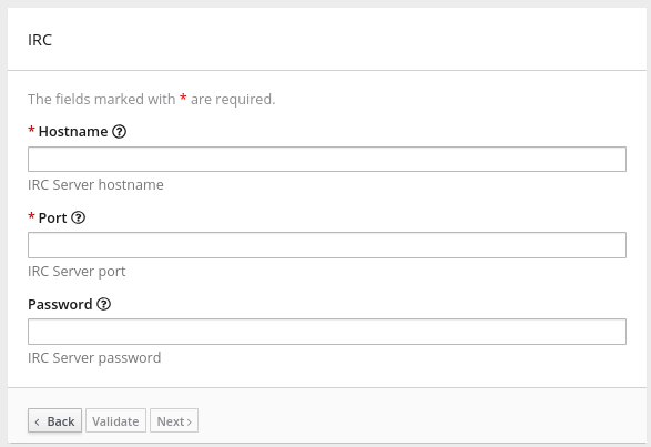
About properties objects in extension definition JSON files
In a connector extension:
-
The toplevel
propertiesobject is required. It controls what Fuse Online displays when a Fuse Online user selects the connector to create a connection. Thispropertiesobject contains a set of properties for each form control for creating a connection. -
In the
actionsobject, there is apropertiesobject for each action. In each of thesepropertiesobjects, there is a set of properties for each form control for configuring that action.
In a step extension, the actions object contains a properties object. The properties object defines a set of properties for each form control for configuring the step. The JSON hierarchy looks like this:
"actions": [
   {
      ...

      "propertyDefinitionSteps": [
         {
            ...

            "properties":
               {
                  "control-ONE": {
                     "type": "string",
                     "displayName": "Topic Name",
                     "order": "2",
                     ...,
                     }

                  "control-TWO": {
                     "type": "boolean",
                     "displayName": "Urgent",
                     "order": "3",
                     ...
                     }

                  "control-THREE": {
                     "type": "textarea",
                     "displayName": "Comment",
                     "order": "1",
                     ...,
                     }
 } } ]
About user interface properties in Java files
To define user interface form controls in Java files, import io.syndesis.extension.api.annotations.ConfigurationProperty in each class file that defines user configuration of a connection, action, or step. For each form control that you want the Fuse Online console to display, specify the @ConfigurationProperty annotation, followed by a list of properties. For information about the properties that you can specify, see the user interface property reference table at the end of this section.
The following code shows property definitions for one form control. This code is in the example of developing a Camel route with RouteBuilder:
public class LogAction extends RouteBuilder {
    @ConfigurationProperty(
        name = "prefix",
        description = "The Log body prefix message",
        displayName = "Log Prefix",
        type = "string")
The following code shows property definitions for two controls. This code is from the example of using the Syndesis Step API:
@Action(id = "split", name = "Split", description = "Split your exchange")
public class SplitAction implements Step {

    @ConfigurationProperty(
        name = "language",
        displayName = "Language",
        description = "The language used for the expression")
    private String language;

    @ConfigurationProperty(
        name = "expression",
        displayName = "Expression",
        description = "The expression used to split the exchange
     private String language;
Descriptions of control form input types
In the set of properties for each HTML form control, the type property defines the input type of the form control that Fuse Online displays. For details about HTML form input types, see https://www.w3schools.com/html/html_form_input_types.asp.
The following table lists the possible input types for Fuse Online form controls. In the set of properties for a control, if you specify a type value that is unknown, Fuse Online displays an input field that accepts one line of text. That is, the default is "type": "text".
Value of type property | HTML | Fuse Online displays |
|---|---|---|
|
|
| A checkbox that the user can select or not select. |
|
|
A custom control that lets the Fuse Online user select a unit of time: milliseconds, seconds, minutes, hours, or days. The user also enters a number and Fuse Online returns a number of milliseconds. For example: | |
|
|
| This field does not appear in the Fuse Online console. You can use other properties to specify data that is associated with this field, for example, textual data of some kind. While Fuse Online users cannot see or modify this data, if a user selects View Source for a Fuse Online page, hidden fields are visible in the source display. Therefore, do not use hidden fields for security purposes. |
|
|
| An input field that accepts a number. |
|
|
| An input field in which Fuse Online masks the characters that the user enters, typically with asterisks. |
|
|
A |
A drop-down list with an entry for each label/value pair that you specify in the form control’s |
|
|
| An input field that accepts one line of text. |
|
|
| A textarea element is used |
Descriptions of control form user interface properties
In a connector or step extension, for each HTML form control that appears in the Fuse Online console, you can specify one or more of the properties described in the following table. For details about HTML form input types, see https://www.w3schools.com/html/html_form_input_types.asp.
| Property name | Type | Description |
|---|---|---|
|
| string | Controls the kind of form control that Fuse Online displays. See the previous table for details. |
|
| number |
If set for a |
|
| string |
If set, the value is mapped to the HTML |
|
| array |
If the value of the |
|
|
Varies according to the value of the |
Fuse Online initially displays this value in the form field. The type of the setting of the |
|
| string | If set, Fuse Online displays this value below the form control. Typically, this is a short, useful message about the control. |
|
| string | Fuse Online displays this value. |
|
| array |
If set, Fuse Online overrides any setting for the |
|
| string |
If set, a |
|
| number |
If set for a |
|
| number |
If set for a |
|
| Boolean |
If set to |
|
| number |
Determines the order of controls in the Fuse Online console. Fuse Online applies ascending order, that is, the control that has |
|
| string | If set, Fuse Online displays this value in a hazed font in an input field to help the user understand the expected input. |
|
| Boolean |
Controls whether or not the |
|
| number |
If the value of the |
|
| Boolean |
If specified, Fuse Online changes the setting of the control’s |
9.3.6. Description of Maven plugin that supports extensions
The extension-maven-plugin supports extension development by packaging the extension as a valid Spring Boot module. For step extensions that you implement in Java, this plugin can generate the extension definition JSON file.
In your Maven project’s pom.xml file, add the following plugin declaration:
<plugin>
    <groupId>io.syndesis.extension</groupId>
    <artifactId>extension-maven-plugin</artifactId>
    <version>${syndesis.version}</version>
    <executions>
        <execution>
        <goals>
            <goal>generate-metadata</goal>
            <goal>repackage-extension</goal>
        </goals>
        </execution>
    </executions>
</plugin>
The extension-maven-plugin defines the following goals:
generate-metadata generates the JSON extension definition file that will be in the generated JAR file as follows:
Maven starts with the data structure specifications that are in the
META-INF/syndesis/syndesis-extension-definition.jsonfile, if there is one.If you are coding in XML, then you must define the extension definition JSON file yourself and it must specify all required data structures.
If you are developing a connector or library extension, then you must define the extension definition JSON file yourself and it must specify all required data structures.
If you are developing a step extension in Java, you can:
- Create the extension definition JSON file yourself.
- In your Java code, specify annotations that define all required data structures. You do not create an extension definition JSON file.
- Create an extension definition JSON file and specify some but not all data structures.
- For step extensions that you develop in Java, Maven obtains missing specifications from code annotations
-
Maven adds the dependencies list, which specifies dependencies that are provided with a scope of
providedand that are managed through theextension-bom.
repackage-extension packages the extension.
-
Dependencies and related transitive dependencies that are not managed through the
extension-bomare in thelibfolder of the generated JAR. -
For library extensions, dependencies whose scope is
systemare in thelibfolder of the generated JAR.
-
Dependencies and related transitive dependencies that are not managed through the
For example, suppose your Maven project has the following pom.xml file:
<?xml version="1.0" encoding="UTF-8"?>
<project xmlns="http://maven.apache.org/POM/4.0.0"
         xmlns:xsi="http://www.w3.org/2001/XMLSchema-instance"
         xsi:schemaLocation="http://maven.apache.org/POM/4.0.0 http://maven.apache.org/xsd/maven-4.0.0.xsd">

  <modelVersion>4.0.0</modelVersion>
  <groupId>com.company</groupId>
  <artifactId>my-extension</artifactId>
  <version>1.0.0</version>
  <name>MyExtension</name>
  <description>A Sample Extension</description>
  <packaging>jar</packaging>

  <dependencyManagement>
    <dependencies>
      <dependency>
        <groupId>io.syndesis.extension</groupId>
        <artifactId>extension-bom</artifactId>
        <version>1.3.10</version>
        <type>pom</type>
        <scope>import</scope>
      </dependency>
    </dependencies>
  </dependencyManagement>

  <dependencies>
    <dependency>
      <groupId>io.syndesis.extension</groupId>
      <artifactId>extension-api</artifactId>
      <scope>provided</scope>
    </dependency>
    <dependency>
      <groupId>com.github.lalyos</groupId>
      <artifactId>jfiglet</artifactId>
      <version>0.0.8</version>
    </dependency>
  </dependencies>

  <build>
    <plugins>
      <plugin>
        <groupId>org.apache.maven.plugins</groupId>
        <artifactId>maven-compiler-plugin</artifactId>
        <version>3.7.0</version>
        <configuration>
          <source>1.8</source>
          <target>1.8</target>
        </configuration>
      </plugin>
      <plugin>
        <groupId>io.syndesis.extension</groupId>
        <artifactId>extension-maven-plugin</artifactId>
        <version>1.3.10</version>
        <executions>
          <execution>
            <goals>
              <goal>generate-metadata</goal>
              <goal>repackage-extension</goal>
            </goals>
          </execution>
        </executions>
      </plugin>
    </plugins>
  </build>
</project>
Based on this pom.xml file, the generated extension definition JSON file looks like this:
{
  "name": "MyExtension",
  "description": "A Sample Extension",
  "extensionId": "com.company:my-extension",
  "version": "1.0.0",
  "dependencies": [ {
    "type": "MAVEN",
    "id": "io.syndesis.extension:extension-api:jar:1.3.10"
  } ],
  "extensionType": "Libraries",
  "schemaVersion": "v1"
}
The generated archive has this structure and content:
my-extension-1.0.0.jar
|
+- lib
|  |
|  + jfiglet-0.0.8.jar
|
+- META-INF
  |
  +- MANIFEST.MF
     |
     +- syndesis
        |
        +- syndesis-extension-definition.json
9.3.7. How to specify data shapes in extensions
A data shape holds data type metadata for use by the data mapper. The data mapper transforms this metadata into internal documents that it uses to display the source and target data fields in the data mapper user interface. In an extension definition JSON file for a connector or for a custom step, each action specification defines an input data shape (inputDataShape) and an output data shape (outputDataShape).
When you are developing an extension, it is important to specify data shape properties that allow the data mapper to correctly handle and display the source and target fields. The following data shape properties affect data mapper behavior:
-
kind -
type -
specification -
name -
description
About the kind property
The data shape kind property is represented by the DataShapeKinds enum. The possible values for the kind property are:
javaindicates that the data type is represented by a Java class. Follow the"kind": "java"declaration by specifying a fully qualified class name for thetypeproperty. For example:"outputDataShape": { "kind": "java", "type": "org.apache.camel.component.telegram.model.IncomingMessage" },json-schemaindicates that the data type is represented by a JSON schema. Whenkindis set tojson-schema, specify a JSON schema as the value of the data shape’sspecificationproperty. For example:"inputDataShape": { "description": "Person data", "kind": "json-schema", "name": "Person", "specification": "{\"$schema\":\"http://json-schema.org/draft-04/schema#\",\"title\":\"Person\",\"type\":\"object\",\"properties\":{\"firstName\":{...}}}" }The code for the SAP Concur connector contains examples of data shapes that are specified by JSON schemas.
json-instanceindicates that the data type is represented by a JSON instance. Whenkindis set tojson-instance, specify a JSON instance as the value of the data shape’sspecificationproperty. For example:"inputDataShape": { "description": "Person data", "kind": "json-instance", "name": "Person", "specification": "{\"firstName\":\"John\",...}" }xml-schemaindicates that the data type is represented by an XML schema. Whenkindis set toxml-schema, specify an XML Schema as the value of the data shape’sspecificationproperty. For example:"inputDataShape": { "description": "Person data", "kind": "xml-schema", "name": "Person", "specification": "<?xml version=\"1.0\" encoding=\"UTF-8\" ?><xs:schema xmlns:xs=\"http://www.w3.org/2001/XMLSchema\">...</xs:schema>" }xml-instanceindicates that the data type is represented by an XML instance. Whenkindis set toxml-instance, specify an XML instance as the value of the data shape’sspecificationproperty. For example:"inputDataShape": { "description": "Person data", "kind": "xml-instance", "name": "Person", "specification": "<?xml version=\"1.0\" encoding=\"UTF-8\" ?><Person><firstName>Jane</firstName></Person>" }anyindicates that the data type is not structured. For example, it might be a byte array or free format text. The data mapper ignores a data shape when itskindproperty is set toany. In other words, the data does not appear in the data mapper and therefore you cannot map any fields to or from this data.However, for a custom connector, when its
kindproperty is set toany, Fuse Online prompts you to specify input and/or output data types when you configure a connection that you have created from the custom connector. This happens when you add a connection to an integration. You can specify the kind of the data shape’s schema, an appropriate document for the kind of schema that you specify, and a name for the data type.-
noneindicates that there is no data type. For an input data shape, this indicates that the connection or step does not read data. For an output data shape, this indicates that the connection or step does not modify data. For example, when an input message body is being transferred to an output message body, setting thekindproperty tononeindicates that the data is only passing through. The data mapper ignores data shapes whenkindis set tonone. In other words, the data does not appear in the data mapper and therefore you cannot map any fields to or from this data.
About the type property
When the value of the kind property is java, the "kind": "java" declaration is followed by a type declaration that specifies a fully qualified Java class name. For example:
"outputDataShape": {
     "kind": "java",
     "type": "org.apache.camel.component.telegram.model.IncomingMessage"
},
When the kind property is set to anything other than java then any setting for the type property is ignored.
About the specification property
The setting of the kind property determines the setting of the specification property, as shown in the following table.
kind property setting | specification property setting |
|---|---|
|
| Java inspection result.
For each extension that you write in Java, use
As a reminder, for step extensions written in Java, |
|
| An actual JSON schema document. The setting cannot be a reference to a document and the JSON schema cannot point to other JSON schema documents by means of references. |
|
| An actual JSON document that contains example data. The data mapper derives the data types from the example data. The setting cannot be a reference to a document. |
|
| An actual XML schema document. The setting cannot be a reference to a document and the XML schema cannot point to other XML schema documents by means of references. |
|
| An actual XML instance document. The setting cannot be a reference to a document. |
|
|
The |
|
|
The |
About the name property
The data shape name property specifies a human readable name for the data type. The data mapper displays this name in its user interface as the label for the data fields. In the following image, Person is an example of where you would see the value of the name property.

This name also appears in data type indicators in the Fuse Online flow visualization.
About the description property
The data shape description property specifies text that appears as a tooltip when the cursor hovers over the data type name in the data mapper user interface.
9.3.8. Examples of developing step extensions
A step extension implements one or more custom steps. Each custom step implements one action for processing integration data between connections. The following examples demonstrate the alternatives for developing step extensions:
- Section 9.3.8.1, “Example of developing a Camel route with XML fragments”
-
Section 9.3.8.2, “Example of developing a Camel route with
RouteBuilder” -
Section 9.3.8.3, “Example of developing a Camel route with
RouteBuilderand Spring Boot” - Section 9.3.8.4, “Example of using a Camel bean”
- Section 9.3.8.5, “Example of using the Syndesis Step API”
Syndesis provides custom Java annotations that you can use in conjunction with the syndesis-extension-plugin. When you implement a step extension or a connector extension in Java, you can specify annotations that enable Maven to add action definitions to the extension definition JSON file. To enable annotation processing, add the following dependency to your Maven project:
<dependency>
  <groupId>io.syndesis.extension</groupId>
  <artifactId>extension-annotation-processor</artifactId>
  <optional>true</optional>
</dependency>
Because Spring Boot is the integration runtime, to inject beans into a Camel context, be sure to follow standard Spring Boot practices. For example, create an auto-configuration class and create beans there. However, the default behavior is that extension code is not subject to package scanning. Consequently, you must create and populate the META-INF/spring.factories file in a step extension.
9.3.8.1. Example of developing a Camel route with XML fragments
To develop a custom step, you can implement the action as an XML fragment that is a Camel route that has an input such as direct. The Syndesis runtime invokes this route in the same way that it invokes any other Camel route.
For example, suppose that you want to create a step that logs the body of a message with an optional prefix. The following XML defines a Camel route that does this.
<?xml version="1.0" encoding="UTF-8"?>
<routes xmlns="http://camel.apache.org/schema/spring"
    xmlns:xsi="http://www.w3.org/2001/XMLSchema-instance"
    xsi:schemaLocation="
      http://camel.apache.org/schema/spring
      http://camel.apache.org/schema/spring/camel-spring.xsd">

  <route id="log-body-with-prefix">
    <from uri="direct:log"/>
    <choice>
      <when>
        <simple>${header.prefix} != ''</simple>
        <log message="${header.prefix} ${body}"/>
      </when>
      <otherwise>
        <log message="Output ${body}"/>
      </otherwise>
    </choice>
  </route>

</routes>
When you develop an extension in XML, you must create the extension definition JSON file yourself. For this XML fragment, the src/main/resources/META-INF/syndesis/syndesis-extension-definition.json file could define the action as follows:
{
  "actionType": "step",
  "id": "log-body-with-prefix",
  "name": "Log body with prefix",
  "description": "A simple body log with a prefix",
  "descriptor": {
    "kind": "ENDPOINT", 1
    "entrypoint": "direct:log", 2
    "resource": "classpath:log-body-action.xml", 3
    "inputDataShape": {
      "kind": "none"
    },
    "outputDataShape": {
      "kind": "none"
    },
  "propertyDefinitionSteps": [ {
    "description": "extension-properties",
    "name": "extension-properties",
    "properties": { 4
      "prefix": {
        "componentProperty": false,
        "deprecated": false,
        "description": "The Log body prefix message",
        "displayName": "Log Prefix",
        "javaType": "String",
        "kind": "parameter",
        "required": false,
        "secret": false,
        "type": "string"
      }
    }
  } ]
  }
}- 1
- The type of the action is set to
ENDPOINT. The runtime invokes a Camel endpoint to execute the action provided by this custom step. - 2
- The Camel endpoint to invoke is
direct:log. This is thefromspecification in the route. - 3
- This is the location of the XML fragment.
- 4
- These are the properties that the action defined in this custom step exposes to the integrator who will be adding this step to an integration. In Fuse Online, each value that the integrator specifies in the user interface gets mapped to a message header that has the same name as the property. In this example, the integrator will see one input field, with the Log Prefix display name. For more details, see Descriptions of user interface properties.
Syndesis does not support full Camel XML configuration. Syndesis supports only the <routes> tag.
9.3.8.2. Example of developing a Camel route with RouteBuilder
You can implement a custom step by developing an action as a Camel route with the support of the RouteBuilder class. Such a route has an input such as direct. Syndesis invokes this route in the same way that it invokes any other Camel route.
To implement the example that creates a step that logs the body of a message with an optional prefix, you can write something like this:
import org.apache.camel.builder.RouteBuilder;

import io.syndesis.extension.api.annotations.Action;
import io.syndesis.extension.api.annotations.ConfigurationProperty;

@Action( 1
    id = "log-body-with-prefix",
    name = "Log body with prefix",
    description = "A simple body log with a prefix",
    entrypoint = "direct:log")
public class LogAction extends RouteBuilder {
    @ConfigurationProperty( 2
        name = "prefix",
        description = "The Log body prefix message",
        displayName = "Log Prefix",
        type = "string")
    private String prefix;

    @Override
    public void configure() throws Exception {
        from("direct::start") 3
            .choice()
                .when(simple("${header.prefix} != ''"))
                    .log("${header.prefix} ${body}")
                .otherwise()
                    .log("Output ${body}")
            .endChoice();
    }
}
- 1
- The
@Actionannotation indicates the action definition. - 2
- The
@ConfigurationPropertyannotation indicates definitions of user interface form controls. For details, see Descriptions of user interface properties. - 3
- This is the action implementation.
This Java code uses Syndesis annotations, which means that the extension-maven-plugin can automatically generate the action definition. In the extension definition JSON file, the action definition will look like this:
{
  "id": "log-body-with-prefix",
  "name": "Log body with prefix",
  "description": "A simple body log with a prefix",
  "descriptor": {
    "kind": "ENDPOINT", 1
    "entrypoint": "direct:log", 2
    "resource": "class:io.syndesis.extension.log.LogAction", 3
    "inputDataShape": {
      "kind": "none"
    },
    "outputDataShape": {
      "kind": "none"
    },
    "propertyDefinitionSteps": [ {
      "description": "extension-properties",
      "name": "extension-properties",
      "properties": { 4
        "prefix": {
          "componentProperty": false,
          "deprecated": false,
          "description": "The Log body prefix message",
          "displayName": "Log Prefix",
          "javaType": "java.lang.String",
          "kind": "parameter",
          "required": false,
          "secret": false,
          "type": "string",
          "raw": false
        }
      }
    } ]
  },
  "actionType": "step"
}- 1
- The type of action is
ENDPOINT. The runtime invokes a Camel endpoint to execute the action that this step implements. - 2
- This is the Camel endpoint to invoke. It is the
fromspecification in the route. - 3
- This is the class that implements
RoutesBuilder. - 4
- These are the properties that the action defined in this custom step exposes to the integrator who will be adding this step to an integration. In Fuse Online, each value that the integrator specifies in the user interface gets mapped to a message header that has the same name as the property. In this example, the integrator will see one input field, with the Log Prefix display name. For more information, see Descriptions of user interface properties.
9.3.8.3. Example of developing a Camel route with RouteBuilder and Spring Boot
You can implement a custom step by developing an action as a Camel route with the support of the RouteBuilder class as well as Spring Boot. In this example, Spring Boot is the facility for registering a RouteBuilder object in a Camel context. Syndesis invokes this route in the same way that it invokes any other Camel route.
To implement the example that creates a step that logs the body of a message with an optional prefix, you can write something like this:
import io.syndesis.extension.api.annotations.Action;
import io.syndesis.extension.api.annotations.ConfigurationProperty;
import org.apache.camel.builder.RouteBuilder;
import org.springframework.context.annotation.Bean;
import org.springframework.context.annotation.Configuration;

@Configuration
public class ActionsConfiguration {

    @Action( 1
        id = "log-body-with-prefix",
        name = "Log body with prefix",
        description = "A simple body log with a prefix",
        entrypoint = "direct:log")
    @ConfigurationProperty( 2
        name = "prefix",
        description = "The Log body prefix message",
        displayName = "Log Prefix",
        type = "string")
    @Bean 3
    public RouteBuilder logBodyWithprefix() {
        return new RouteBuilder() {
            @Override
            public void configure() throws Exception {
                from("direct::start") 4
                    .choice()
                        .when(simple("${header.prefix} != ''"))
                            .log("${header.prefix} ${body}")
                        .otherwise()
                            .log("Output ${body}")
                    .endChoice();
             }
        };
    }
}- 1
- The
@Actionannotation indicates the action definition. - 2
- The
@ConfigurationPropertyannotation indicates definitions of user interface form controls. For details, see Descriptions of user interface properties. - 3
- Register the
RouteBuilderobject as a bean. - 4
- This is the action implementation.
This Java code uses Syndesis annotations, which means that the extension-maven-plugin can automatically generate the action definition. In the extension definition JSON file, the action definition will look like this:
{
  "id": "log-body-with-prefix",
  "name": "Log body with prefix",
  "description": "A simple body log with a prefix",
  "descriptor": {
    "kind": "ENDPOINT", 1
    "entrypoint": "direct:log", 2
    "inputDataShape": {
      "kind": "none"
    },
    "outputDataShape": {
      "kind": "none"
    },
    "propertyDefinitionSteps": [ {
      "description": "extension-properties",
      "name": "extension-properties",
      "properties": { 3
        "prefix": {
          "componentProperty": false,
          "deprecated": false,
          "description": "The Log body prefix message",
          "displayName": "Log Prefix",
          "javaType": "java.lang.String",
          "kind": "parameter",
          "required": false,
          "secret": false,
          "type": "string",
          "raw": false
        }
      }
    } ]
  },
  "actionType": "step"
}- 1
- The type of action is
ENDPOINT. The runtime invokes a Camel endpoint to execute the action that this step implements. - 2
- This is the Camel endpoint to invoke. It is the
fromspecification in the route. - 3
- These are the properties that the action defined in this custom step exposes to the integrator who will be adding this step to an integration. In Fuse Online, each value that the integrator specifies in the user interface gets mapped to a message header that has the same name as the property. In this example, the integrator will see one input field, with the Log Prefix display name. For more details, see Descriptions of user interface properties.
To make configuration classes discoverable by Spring Boot, you must list them in a file named META-INF/spring.factories, for example:
org.springframework.boot.autoconfigure.EnableAutoConfiguration=com.company.ActionsConfiguration
With Spring Boot, every bean that you eventually register in your configuration classes is available to the Camel context. For details, see the Spring Boot documentation for Creating your own auto-configuration.
9.3.8.4. Example of using a Camel bean
You can implement a custom step by developing an action as a Camel bean processor. To implement the example that creates a step that logs the body of a message with an optional prefix, you can write something like this:
import org.apache.camel.Body;
import org.apache.camel.Handler;
import org.apache.camel.Header;
import org.slf4j.Logger;
import org.slf4j.LoggerFactory;

import io.syndesis.extension.api.annotations.Action;
import io.syndesis.extension.api.annotations.ConfigurationProperty;

@Action(
    id = "log-body-with-prefix",
    name = "Log body with prefix",
    description = "A simple body log with a prefix")
public class LogAction  {
    private static final Logger LOGGER = LoggerFactory.getLogger(LogAction.class);

    @ConfigurationProperty(
        name = "prefix",
        description = "The Log body prefix message",
        displayName = "Log Prefix",
        type = "string")
    private String prefix;

    @Handler 1
    public void process(@Header("prefix") String prefix, @Body Object body) {
        if (prefix == null) {
            LOGGER.info("Output {}", body);
        } else {
            LOGGER.info("{} {}", prefix, body);
        }
    }
}- 1
- This is the function that implements the action.
This Java code uses Syndesis annotations, which means that the extension-maven-plugin can automatically generate the action definition. In the extension definition JSON file, the action definition will look like this:
{
  "id": "log-body-with-prefix",
  "name": "Log body with prefix",
  "description": "A simple body log with a prefix",
  "descriptor": {
    "kind": "BEAN", 1
    "entrypoint": "io.syndesis.extension.log.LogAction::process", 2
    "inputDataShape": {
      "kind": "none"
    },
    "outputDataShape": {
      "kind": "none"
    },
    "propertyDefinitionSteps": [ {
      "description": "extension-properties",
      "name": "extension-properties",
      "properties": {
        "prefix": { 3
          "componentProperty": false,
          "deprecated": false,
          "description": "The Log body prefix message",
          "displayName": "Log Prefix",
          "javaType": "java.lang.String",
          "kind": "parameter",
          "required": false,
          "secret": false,
          "type": "string",
          "raw": false
        }
      }
    } ]
  },
  "actionType": "step"
}- 1
- The type of the action is
BEAN. The runtime invokes a Camel bean processor to execute the action in this custom step. - 2
- This is the Camel bean to invoke.
- 3
- These are the properties that the action defined in this custom step exposes to the integrator who will be adding this step to an integration. In Fuse Online, each value that the integrator specifies in the user interface gets mapped to a message header that has the same name as the property. In this example, the integrator will see one input field, with the Log Prefix display name. For more details, see Descriptions of user interface properties.
When you use beans, you might find it convenient to inject user properties into the bean instead of retrieving them from the exchange header. To do this, implement getter and setter methods for the properties that you want to get injected. The action implementation would look like this:
import org.apache.camel.Body;
import org.apache.camel.Handler;
import org.slf4j.Logger;
import org.slf4j.LoggerFactory;

import io.syndesis.extension.api.annotations.Action;
import io.syndesis.extension.api.annotations.ConfigurationProperty;

@Action(
    id = "log-body-with-prefix",
    name = "Log body with prefix",
    description = "A simple body log with a prefix")
public class LogAction  {
    private static final Logger LOGGER = LoggerFactory.getLogger(LogAction.class);

    @ConfigurationProperty(
        name = "prefix",
        description = "The Log body prefix message",
        displayName = "Log Prefix",
        type = "string")
    private String prefix;

    public void setPrefix(String prefix) { 1
        this.prefix = prefix;
    }

    public String getPrefix() { 2
        return prefix;
    }

    @Handler
    public void process(@Body Object body) {
        if (this.prefix == null) {
            LOGGER.info("Output {}", body);
        } else {
            LOGGER.info("{} {}", this.prefix, body);
        }
    }
}9.3.8.5. Example of using the Syndesis Step API
You can implement a custom step by using the Syndesis Step API. This provides a way to interact with runtime route creation. You can use any method provided by the ProcessorDefinition class and you can create more complex routes. Information for the Syndesis API is at http://javadoc.io/doc/io.syndesis.extension/extension-api.
Here is an example of a step extension that uses the Syndesis Step API to implement a split action:
import java.util.Map;
import java.util.Optional;

import io.syndesis.extension.api.Step;
import io.syndesis.extension.api.annotations.Action;
import io.syndesis.extension.api.annotations.ConfigurationProperty;
import org.apache.camel.CamelContext;
import org.apache.camel.model.ProcessorDefinition;
import org.apache.camel.util.ObjectHelper;
import org.apache.camel.Expression;
import org.apache.camel.builder.Builder;
import org.apache.camel.processor.aggregate.AggregationStrategy;
import org.apache.camel.processor.aggregate.UseOriginalAggregationStrategy;
import org.apache.camel.spi.Language;

@Action(id = "split", name = "Split", description = "Split your exchange")
public class SplitAction implements Step {

    @ConfigurationProperty(
        name = "language",
        displayName = "Language",
        description = "The language used for the expression")
    private String language;

    @ConfigurationProperty(
        name = "expression",
        displayName = "Expression",
        description = "The expression used to split the exchange")
    private String expression;

    public String getLanguage() {
        return language;
    }

    public void setLanguage(String language) {
        this.language = language;
    }

    public String getExpression() {
        return expression;
    }

    public void setExpression(String expression) {
        this.expression = expression;
    }

    @Override
    public Optional<ProcessorDefinition> configure(
            CamelContext context,
            ProcessorDefinition route,
            Map<String, Object> parameters) { 1

        String languageName = language;
        String expressionDefinition = expression;

        if (ObjectHelper.isEmpty(languageName) && ObjectHelper.isEmpty(expressionDefinition)) {
            route = route.split(Builder.body());
        } else if (ObjectHelper.isNotEmpty(expressionDefinition)) {

            if (ObjectHelper.isEmpty(languageName)) {
                languageName = "simple";
            }

            final Language splitLanguage = context.resolveLanguage(languageName);
            final Expression splitExpression = splitLanguage.createExpression(expressionDefinition);
            final AggregationStrategy aggreationStrategy = new UseOriginalAggregationStrategy(null, false);

            route = route.split(splitExpression).aggregationStrategy(aggreationStrategy);
        }

        return Optional.of(route);
    }
}- 1
- This is the implementation of the action that the custom step performs.
This Java code uses Syndesis annotations, which means that the extension-maven-plugin can automatically generate the action definition. In the extension definition JSON file, the action definition will look like this:
{
  "id": "split",
  "name": "Split",
  "description": "Split your exchange",
  "descriptor": {
    "kind": "STEP", 1
    "entrypoint": "io.syndesis.extension.split.SplitAction", 2
    "inputDataShape": {
      "kind": "none"
    },
    "outputDataShape": {
      "kind": "none"
    },
    "propertyDefinitionSteps": [ {
      "description": "extension-properties",
      "name": "extension-properties",
      "properties": {
        "language": {
          "componentProperty": false,
          "deprecated": false,
          "description": "The language used for the expression",
          "displayName": "Language",
          "javaType": "java.lang.String",
          "kind": "parameter",
          "required": false,
          "secret": false,
          "type": "string",
          "raw": false
        },
        "expression": {
          "componentProperty": false,
          "deprecated": false,
          "description": "The expression used to split the exchange",
          "displayName": "Expression",
          "javaType": "java.lang.String",
          "kind": "parameter",
          "required": false,
          "secret": false,
          "type": "string",
          "raw": false
        }
      }
    } ]
  },
  "tags": [],
  "actionType": "step"
}Additional resource
For details about user interface properties, see Descriptions of user interface properties.
9.3.9. Example of developing a connector extension
If Fuse Online does not provide a connector for the application or service that you want to connect to in an integration, an experienced developer can code an extension that contributes a new connector to Fuse Online. This documentation provides an introduction to developing a connector extension. For details about developing a connector, see Developing Syndesis connectors on the Syndesis community site.
For connector extensions, it is not yet possible to automatically generate the extension definition JSON file from Java code.
A connector is essentially a proxy for a Camel component. A connector configures the underlying component and creates endpoints according to options that are defined in the extension definition and in user-supplied options that the Fuse Online web interface collects.
The connector extension definition extends the extension definition that is required for step extensions with the following additional data structures:
componentSchemeDefines the Camel component that the connector uses. You can set
componentSchemefor the connector or for actions. If you setcomponentSchemefor both the connector and an action, the setting for the action has precedence.connectorCustomizersSpecifies a list of classes that implement the ComponentProxyCustomizer class. Each class customizes the behavior of a connector. For example, a class might manipulate properties before they are applied to the underlying component/endpoint, or a class might add pre/post endpoint logic. For each class, specify the full class name of the implementation, for example,
com.mycomponent.MyCustomizer. You can setconnectorCustomizerson actions as well as connectors. According to what is set, Fuse Online applies customizers to the connector first and then to actions.connectorFactoryDefines the class that implements the ComponentProxyFactory class, which creates and/or configures the underlying component/endpoint. Specify the full class name of the implementation. You can set
connectorFactoryfor the connector or for actions. Actions have precedence.
Customizer example
The following customizer example sets up a DataSource from individual options:
public class DataSourceCustomizer implements ComponentProxyCustomizer, CamelContextAware {
    private final static Logger LOGGER = LoggerFactory.getLogger(DataSourceCustomizer.class);

    private CamelContext camelContext;

    @Override
    public void setCamelContext(CamelContext camelContext) { 1
        this.camelContext = camelContext;
    }

    @Override
    public CamelContext getCamelContext() { 2
        return this.camelContext;
    }

    @Override
    public void customize(ComponentProxyComponent component, Map<String, Object> options) {
        if (!options.containsKey("dataSource")) {
            if (options.containsKey("user") && options.containsKey("password") && options.containsKey("url")) {
                try {
                    BasicDataSource ds = new BasicDataSource();

                    consumeOption(camelContext, options, "user", String.class, ds::setUsername); 3
                    consumeOption(camelContext, options, "password", String.class, ds::setPassword); 4
                    consumeOption(camelContext, options, "url", String.class, ds::setUrl); 5

                    options.put("dataSource", ds);
                } catch (@SuppressWarnings("PMD.AvoidCatchingGenericException") Exception e) {
                    throw new IllegalArgumentException(e);
                }
            } else {
                LOGGER.debug("Not enough information provided to set-up the DataSource");
            }
        }
    }
}Example of injecting properties
If the customizer respects Java bean conventions, you can also inject the properties, as shown in this revision of the previous example:
public class DataSourceCustomizer implements ComponentProxyCustomizer, CamelContextAware {
    private final static Logger LOGGER = LoggerFactory.getLogger(DataSourceCustomizer.class);

    private CamelContext camelContext;
    private String userName;
    private String password;
    private String url;

    @Override
    public void setCamelContext(CamelContext camelContext) { 1
        this.camelContext = camelContext;
    }

    @Override
    public CamelContext getCamelContext() { 2
        return this.camelContext;
    }

    public void setUserName(String userName) { 3
      this.userName = userName;
    }

    public String getUserName() { 4
      return this.userName;
    }

    public void setPassword(String password) { 5
      this.password = password;
    }

    public String getPassword() { 6
      return this.password;
    }

    public void setUrl(String url) { 7
      this.url = url;
    }

    public String getUrl() { 8
      return this.url;
    }

    @Override
    public void customize(ComponentProxyComponent component, Map<String, Object> options) {
        if (!options.containsKey("dataSource")) {
            if (userName != null && password != null && url != null) {
                try {
                    BasicDataSource ds = new BasicDataSource();
                    ds.setUserName(userName);
                    ds.setPassword(password);
                    ds.setUrl(url);

                    options.put("dataSource", ds);
                } catch (@SuppressWarnings("PMD.AvoidCatchingGenericException") Exception e) {
                    throw new IllegalArgumentException(e);
                }
            } else {
                LOGGER.debug("Not enough information provided to set-up the DataSource");
            }
        }
    }
}- 1 2 3
- By implementing
CamelContextAware, Syndesis injects the Camel context and then invokes the customize method. This sample code overrides thesetCamelContext()andgetCamelContext()methods, and sets the user name. - 4 5 6 7 8
- The sample code processes the injected options and automatically removes them from the options map.
Using a customizer to configure before/after logic
You can use a customizer to configure before/after logic as shown in this example:
public class AWSS3DeleteObjectCustomizer implements ComponentProxyCustomizer {
  	private String filenameKey;

    public void setFilenameKey(String filenameKey) {
      this.filenameKey = filenameKey;
    }

    public String getFilenameKey() {
        return this.filenameKey;
    }

    @Override
    public void customize(ComponentProxyComponent component, Map<String, Object> options) {
      	component.setBeforeProducer(this::beforeProducer);
    }

    public void beforeProducer(final Exchange exchange) throws IOException {
      	exchange.getIn().setHeader(S3Constants.S3_OPERATION, S3Operations.deleteObject);

    	  if (filenameKey != null) {
    		    exchange.getIn().setHeader(S3Constants.KEY, filenameKey);
    	  }
    }
}
Customizing behavior of ComponentProxyComponent
The ComponentProxyFactory class creates and/or configures the underlying component/endpoint. To customize the behavior of the ComponentProxyComponent object that ComponentProxyFactory creates, you can override any of the following methods:
createDelegateComponent()Syndesis invokes this method when the proxy starts and it is used to eventually create a dedicated instance of the component with the scheme defined by the
componentSchemeoption.The default behavior of this method is to determine if any of the connector/action options applies at the component level. Only in the case that the same option cannot be applied at the endpoint, the method creates a custom component instance and configures it according to the applicable options.
configureDelegateComponent()Syndesis invokes this method only if a custom component instance has been created to configure additional behavior of the delegated component instance.
createDelegateEndpoint()Syndesis invokes this method when the proxy creates the endpoint and by default creates the endpoint by using Camel catalog facilities.
configureDelegateEndpoint()After the delegated endpoint has been created, Syndesis invokes this method to configure additional behavior of the delegated endpoint instance, for example:
public class IrcComponentProxyFactory implements ComponentProxyFactory {

    @Override
    public ComponentProxyComponent newInstance(String componentId, String componentScheme) {
        return new ComponentProxyComponent(componentId, componentScheme) {
            @Override
            protected void configureDelegateEndpoint(ComponentDefinition definition, Endpoint endpoint, Map<String, Object> options) throws Exception {
                if (!(endpoint instanceof IrcEndpoint)) {
                    throw new IllegalStateException("Endpoint should be of type IrcEndpoint");
                }

                final IrcEndpoint ircEndpoint = (IrcEndpoint)endpoint;
                final String channels = (String)options.remove("channels");

                if (ObjectHelper.isNotEmpty(channels)) {
                    ircEndpoint.getConfiguration().setChannel(
                        Arrays.asList(channels.split(","))
                    );
                }
            }
        };
    }
}
9.3.10. How to develop library extensions
A library extension provides a resource that an integration requires at runtime. A library extension does not contribute steps or connectors to Fuse Online.
When you save an integration, you can optionally select one or more imported library extensions that you want to include with the integration.
A library extension does not define any actions. Here is a sample definition for a library extension:
{
  "schemaVersion" : "v1",
  "name" : "Example Library Extension",
  "description" : "Syndesis Extension for adding a runtime library",
  "extensionId" : "io.syndesis.extensions:syndesis-library",
  "version" : "1.0.0",
  "tags" : [ "my-libraries-extension" ],
  "extensionType" : "Libraries"
}
See also the sample library extension here: https://github.com/syndesisio/syndesis-extensions
Other than the lack of actions, the structure of a library extension is the same as the structure of a step or connector extension.
In a Maven project that creates a library extension, to add dependencies that are not available from a Maven repository, specify a system dependency, for example:
<dependency>
    <groupId>com.company</groupId>
    <artifactId>my-library-extension</artifactId>
    <version>1.0</version>
    <scope>system</scope>
    <systemPath>${project.basedir}/lib/my-library-extension.jar</systemPath>
</dependency>
9.3.11. Creating JDBC driver library extensions
To connect to a SQL database other than Apache Derby, MySQL, and PostgreSQL, you can create a library extension that wraps a JDBC driver for the database you want to connect to. After uploading this extension to Fuse Online, the Fuse Online-provided Database connector can access the driver to validate and create connections to the proprietary database. You do not create a new connector for your particular database.
The Syndesis open source community provides a project for creating an extension that wraps a JDBC driver.
Package one driver only in an extension. This makes it easier to manage the extension as part of managing your particular database. However, it is possible to create a library extension that wraps more than one driver.
Prerequisites
To use the Syndesis project, you must have a GitHub account.
Procedure
Ensure access to the JDBC driver for the database you want to connect to by doing one of the following:
- Confirm that the driver is in a Maven repository.
- Download the driver.
- In a browser tab, go to https://github.com/syndesisio/syndesis-extensions
-
Fork the
syndesis-extensionsrepository to your GitHub account. - Create a local clone from your fork.
In your
syndesis-extensionsclone:-
If the driver is not in a Maven repository, copy the driver into the
syndesis-library-jdbc-driver/libfolder. Edit the
syndesis-library-jdbc-driver/pom.xmlfile:-
Update the value of the
Nameelement to be a name that you choose for this extension. -
Update the value of the
Descriptionelement to provide helpful information about this extension. -
If you have copied the driver into
syndesis-library-jdbc-driver/libensure that thesystemPathinpom.xmlpoints to that driver file. Optionally change thegroupId,artifactIdandversionto reflect proper values according to the driver. -
If the driver is in a Maven repository, ensure that a reference to that Maven dependency is in the
pom.xmlfile. -
Examine the rest of the content of the
pom.xmlfile and change any relevant metadata as needed.
-
Update the value of the
-
Execute
./mvnw -pl :syndesis-library-jdbc-driver clean packageto build the extension.
-
If the driver is not in a Maven repository, copy the driver into the
The generated .jar file is in the syndesis-library-jdbc-driver/target folder. Import this .jar file as an extension in Fuse Online.
After you import a library extension, when you save an integration in Fuse Online you can optionally select the imported library extension and associate it with the integration.
9.4. Adding and managing extensions
Extensions let you add customizations to Fuse Online so you can integrate applications the way you want to. After you start using customizations provided in extensions, you can identify the integrations that use those customizations. This is helpful to do before you update or delete an extension.
The following topics provide details:
9.4.1. Making custom features available
To make a custom feature available for use in an integration, upload the extension to Fuse Online.
Prerequisites
-
A developer has provided a
.jarfile that contains a Fuse Online extension.
Procedure
- In the left Fuse Online panel, click Customizations > Extensions.
- Click Import Extension.
Drag and drop, or choose, the
.jarfile that contains the extension that you want to upload.Fuse Online immediately tries to validate that the file contains an extension. If there is a problem, Fuse Online displays a message about the error. You must coordinate with the extension developer to obtain an updated
.jarfile, which you can then try to upload.Review the extension details.
After Fuse Online validates the file, it extracts and displays the extension’s name, ID, description, and type. The type indicates whether the extension defines a custom connector, or one or more custom steps for operating on data between connections, or a runtime library extension (including a JDBC driver).
For a connector extension, Fuse Online displays the actions that are available to a connection that is created from this custom connector. In the extension, the developer might have provided an icon that Fuse Online can use to represent the application connections created from this connector. While you do not see this icon in the extension details page, it appears when you create connections from the custom connector. If the extension developer did not provide an icon in the extension, then Fuse Online generates an icon.
For a step extension, Fuse Online displays the name of each custom step that the extension defines.
For a library extension, Fuse Online includes the imported Maven dependencies in the integration runtime classpath. You must ensure that the imported Maven dependencies do not conflict with other dependencies that are already used in the integration (including any other library extension, such as a JDBC driver).
- Click Import Extension. Fuse Online makes the custom connector or custom step(s) available and displays the extension’s details page.
9.4.2. Identifying integrations that use extensions
Before you update or delete an extension, you should identify the integrations that use customizations that are provided by that extension.
Procedure
- In the left Fuse Online panel, click Customizations > Extensions.
- In the list of extensions, find the entry for the extension that you want to update or delete and click its Details button.
Result
Fuse Online displays details about the extension including a list of any integrations that use a customization provided by the extension.
9.4.3. Updating extensions
When a developer updates an extension, you can upload the updated .jar file to implement the updates in your integrations.
Prerequisite
A developer has provided you with an updated .jar file for an extension that you previously uploaded.
Procedure
- In Fuse Online, in the left panel, click Customizations > Extensions.
- At the right of the entry for the extension that you want to update, click Update.
-
Click in the dotted-line box to navigate to and select the updated
.jarfile, and click Open. - Confirm that the extension details are correct and click Import Extension.
- In the details page for the updated extension, determine which integrations use the connector or custom step(s) defined in the extension.
It is up to you to know exactly what is required to update each integration that uses a custom connector or a custom step from the updated extension. At the very least, you must republish each integration that uses a customization defined in the updated extension.
In some cases, you might need to edit the integration to change or add configuration details for a customization. You must communicate with the extension developer to understand how to update integrations.
9.4.4. Deleting extensions
You can delete an extension even if a running integration uses a step that is provided by that extension or uses a connection that was created from a connector that was provided by that extension. After you delete an extension, you cannot start an integration that uses a customization that was provided by that extension.
Procedure
- In the left Fuse Online panel, click Customizations > Extensions.
- In the list of extensions, find the entry for the extension that you want to delete and click Delete, which appears at the right of the entry.
Results
There might be stopped or draft integrations that use a customization provided by an extension that you delete. To run one of these integrations, you will need to edit the integration to remove the customization.
Additional resources