Load Balancer Administration
Red Hat Enterprise Linux 7
Configuring Keepalived and HAProxy
Abstract
Building a Load Balancer system offers a highly available and scalable solution for production services using specialized Linux Virtual Servers (LVS) for routing and load-balancing techniques configured through Keepalived and HAProxy. This book discusses the configuration of high-performance systems and services using the Load Balancer technologies in Red Hat Enterprise Linux 7.
Chapter 1. Load Balancer Overview
The Load Balancer is a set of integrated software components that provide for balancing IP traffic across a set of real servers. It consists of two main technologies to monitor cluster members and cluster services: Keepalived and HAProxy. Keepalived uses Linux virtual server (LVS) to perform load balancing and failover tasks on the active and passive routers, while HAProxy performs load balancing and high-availability services to TCP and HTTP applications.
1.1. keepalived
The
keepalived daemon runs on both the active and passive LVS routers. All routers running keepalived use the Virtual Redundancy Routing Protocol (VRRP). The active router sends VRRP advertisements at periodic intervals; if the backup routers fail to receive these advertisements, a new active router is elected.
On the active router,
keepalived can also perform load balancing tasks for real servers.
Keepalived is the controlling process related to LVS routers. At boot time, the daemon is started by the
systemctl command, which reads the configuration file /etc/keepalived/keepalived.conf. On the active router, the keepalived daemon starts the LVS service and monitors the health of the services based on the configured topology. Using VRRP, the active router sends periodic advertisements to the backup routers. On the backup routers, the VRRP instance determines the running status of the active router. If the active router fails to advertise after a user-configurable interval, Keepalived initiates failover. During failover, the virtual servers are cleared. The new active router takes control of the virtual IP address (VIP), sends out an ARP message, sets up IPVS table entries (virtual servers), begins health checks, and starts sending VRRP advertisements.
Keepalived performs failover on layer 4, or the Transport layer, upon which TCP conducts connection-based data transmissions. When a real server fails to reply to simple timeout TCP connection,
keepalived detects that the server has failed and removes it from the server pool.
1.2. haproxy
HAProxy offers load balanced services to HTTP and TCP-based services, such as Internet-connected services and web-based applications. Depending on the load balancer scheduling algorithm chosen,
haproxy is able to process several events on thousands of connections across a pool of multiple real servers acting as one virtual server. The scheduler determines the volume of connections and either assigns them equally in non-weighted schedules or given higher connection volume to servers that can handle higher capacity in weighted algorithms.
HAProxy allows users to define several proxy services, and performs load balancing services of the traffic for the proxies. Proxies are made up of a frontend system and one or more back-end systems. The front-end system defines the IP address (the VIP) and port on which the proxy listens, as well as the back-end systems to use for a particular proxy.
The back-end system is a pool of real servers, and defines the load balancing algorithm.
HAProxy performs load-balancing management on layer 7, or the Application layer. In most cases, administrators deploy HAProxy for HTTP-based load balancing, such as production web applications, for which high availability infrastructure is a necessary part of business continuity.
1.3. keepalived and haproxy
Administrators can use both Keepalived and HAProxy together for a more robust and scalable high availability environment. Using the speed and scalability of HAProxy to perform load balancing for HTTP and other TCP-based services in conjunction with Keepalived failover services, administrators can increase availability by distributing load across real servers as well as ensuring continuity in the event of router unavailability by performing failover to backup routers.
Chapter 2. Keepalived Overview
Keepalived runs on an active LVS router as well as one or more optional backup LVS routers. The active LVS router serves two roles:
- To balance the load across the real servers.
- To check the integrity of the services on each real server.
The active (master) router informs the backup routers of its active status using the Virtual Router Redundancy Protocol (VRRP), which requires the master router to send out advertisements at regular intervals. If the active router stops sending advertisements, a new master is elected.
Note
Red Hat does not support rolling updates of keepalived where the configuration changes the VRRP version to use. All routers must be running the same version of VRRP in a keepalived load balancer configuration. A VRRP version mismatch will lead to the following messages:
Aug  3 17:07:19 hostname Keepalived_vrrp[123]: receive an invalid ip number count associated with VRID!
Aug  3 17:07:19 hostname Keepalived_vrrp[123]: bogus VRRP packet received on em2 !!!
Aug  3 17:07:19 hostname Keepalived_vrrp[123]: VRRP_Instance(vrrp_ipv6) ignoring received advertisment...
Red Hat recommend that all systems should run the same keepalived version and keepalived configurations should be identical where possible to avoid compatibility issues.
2.1. A Basic Keepalived Load Balancer Configuration
Figure 2.1, “A Basic Load Balancer Configuration” shows a simple Keepalived Load Balancer configuration consisting of two layers. On the first layer is one active and several backup LVS routers. Each LVS router has two network interfaces, one interface on the Internet and one on the private network, enabling them to regulate traffic between the two networks. For this example the active router is using Network Address Translation or NAT to direct traffic from the Internet to a variable number of real servers on the second layer, which in turn provide the necessary services. Therefore, the real servers in this example are connected to a dedicated private network segment and pass all public traffic back and forth through the active LVS router. To the outside world, the servers appear as one entity.
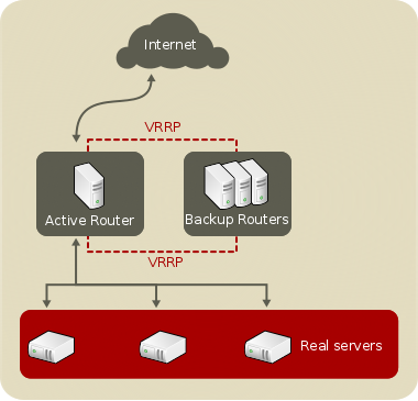
Figure 2.1. A Basic Load Balancer Configuration
Service requests arriving at the LVS router are addressed to a virtual IP address, or VIP. This is a publicly-routable address the administrator of the site associates with a fully-qualified domain name, such as www.example.com, and is assigned to one or more virtual servers. A virtual server is a service configured to listen on a specific virtual IP. A VIP address migrates from one LVS router to the other during a failover, thus maintaining a presence at that IP address. A VIP is also known as a floating IP addresses.
VIP addresses may be assigned to the same device which connects the LVS router to the Internet. For example, if
eth0 is connected to the Internet, then multiple virtual servers can be assigned to eth0. Alternatively, each virtual server can be associated with a separate device per service. For example, HTTP traffic can be handled on eth0 at 192.168.1.111 while FTP traffic can be handled on eth0 at 192.168.1.222.
In a deployment scenario involving both one active and one passive router, the role of the active router is to redirect service requests from virtual IP addresses to the real servers. The redirection is based on one of eight supported load-balancing algorithms described further in Section 2.3, “keepalived Scheduling Overview”.
The active router also dynamically monitors the overall health of the specific services on the real servers through three built-in health checks: simple TCP connect, HTTP, and HTTPS. For TCP connect, the active router will periodically check that it can connect to the real servers on a certain port. For HTTP and HTTPS, the active router will periodically fetch a URL on the real servers and verify its content.
The backup routers perform the role of standby systems. Router failover is handled by VRRP. On startup, all routers will join a multicast group. This multicast group is used to send and receive VRRP advertisements. Since VRRP is a priority based protocol, the router with the highest priority is elected the master. Once a router has been elected master, it is responsible for sending VRRP advertisements at periodic intervals to the multicast group.
If the backup routers fail to receive advertisements within a certain time period (based on the advertisement interval), a new master will be elected. The new master will take over the VIP and send an Address Resolution Protocol (ARP) message. When a router returns to active service, it may either become a backup or a master. The behavior is determined by the router's priority.
The simple, two-layered configuration used in Figure 2.1, “A Basic Load Balancer Configuration” is best for serving data which does not change very frequently — such as static web pages — because the individual real servers do not automatically sync data between each node.
2.2. A Three-Tier keepalived Load Balancer Configuration
Figure 2.2, “A Three-Tier Load Balancer Configuration” shows a typical three-tier Keepalived Load Balancer topology. In this example, the active LVS router routes the requests from the Internet to the pool of real servers. Each of the real servers then accesses a shared data source over the network.
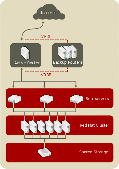
Figure 2.2. A Three-Tier Load Balancer Configuration
This configuration is ideal for busy FTP servers, where accessible data is stored on a central, highly available server and accessed by each real server by means of an exported NFS directory or Samba share. This topology is also recommended for websites that access a central, highly available database for transactions. Additionally, using an active-active configuration with the Load Balancer, administrators can configure one high-availability cluster to serve both of these roles simultaneously.
The third tier in the above example does not have to use the Load Balancer, but failing to use a highly available solution would introduce a critical single point of failure.
2.3. keepalived Scheduling Overview
Using Keepalived provides a great deal of flexibility in distributing traffic across real servers, in part due to the variety of scheduling algorithms supported. Load balancing is superior to less flexible methods, such as Round-Robin DNS where the hierarchical nature of DNS and the caching by client machines can lead to load imbalances. Additionally, the low-level filtering employed by the LVS router has advantages over application-level request forwarding because balancing loads at the network packet level causes minimal computational overhead and allows for greater scalability.
Using assigned weights gives arbitrary priorities to individual machines. Using this form of scheduling, it is possible to create a group of real servers using a variety of hardware and software combinations and the active router can evenly load each real server.
The scheduling mechanism for Keepalived is provided by a collection of kernel patches called IP Virtual Server or IPVS modules. These modules enable layer 4 (L4) transport layer switching, which is designed to work well with multiple servers on a single IP address.
To track and route packets to the real servers efficiently, IPVS builds an IPVS table in the kernel. This table is used by the active LVS router to redirect requests from a virtual server address to and returning from real servers in the pool.
2.3.1. Keepalived Scheduling Algorithms
The structure that the IPVS table takes depends on the scheduling algorithm that the administrator chooses for any given virtual server. To allow for maximum flexibility in the types of services you can cluster and how these services are scheduled, Keepalived supports the following scheduling algorithms listed below.
- Round-Robin Scheduling
- Distributes each request sequentially around the pool of real servers. Using this algorithm, all the real servers are treated as equals without regard to capacity or load. This scheduling model resembles round-robin DNS but is more granular due to the fact that it is network-connection based and not host-based. Load Balancer round-robin scheduling also does not suffer the imbalances caused by cached DNS queries.
- Weighted Round-Robin Scheduling
- Distributes each request sequentially around the pool of real servers but gives more jobs to servers with greater capacity. Capacity is indicated by a user-assigned weight factor, which is then adjusted upward or downward by dynamic load information.Weighted round-robin scheduling is a preferred choice if there are significant differences in the capacity of real servers in the pool. However, if the request load varies dramatically, the more heavily weighted server may answer more than its share of requests.
- Least-Connection
- Distributes more requests to real servers with fewer active connections. Because it keeps track of live connections to the real servers through the IPVS table, least-connection is a type of dynamic scheduling algorithm, making it a better choice if there is a high degree of variation in the request load. It is best suited for a real server pool where each member node has roughly the same capacity. If a group of servers have different capabilities, weighted least-connection scheduling is a better choice.
- Weighted Least-Connections
- Distributes more requests to servers with fewer active connections relative to their capacities. Capacity is indicated by a user-assigned weight, which is then adjusted upward or downward by dynamic load information. The addition of weighting makes this algorithm ideal when the real server pool contains hardware of varying capacity.
- Locality-Based Least-Connection Scheduling
- Distributes more requests to servers with fewer active connections relative to their destination IPs. This algorithm is designed for use in a proxy-cache server cluster. It routes the packets for an IP address to the server for that address unless that server is above its capacity and has a server in its half load, in which case it assigns the IP address to the least loaded real server.
- Locality-Based Least-Connection Scheduling with Replication Scheduling
- Distributes more requests to servers with fewer active connections relative to their destination IPs. This algorithm is also designed for use in a proxy-cache server cluster. It differs from Locality-Based Least-Connection Scheduling by mapping the target IP address to a subset of real server nodes. Requests are then routed to the server in this subset with the lowest number of connections. If all the nodes for the destination IP are above capacity, it replicates a new server for that destination IP address by adding the real server with the least connections from the overall pool of real servers to the subset of real servers for that destination IP. The most loaded node is then dropped from the real server subset to prevent over-replication.
- Destination Hash Scheduling
- Distributes requests to the pool of real servers by looking up the destination IP in a static hash table. This algorithm is designed for use in a proxy-cache server cluster.
- Source Hash Scheduling
- Distributes requests to the pool of real servers by looking up the source IP in a static hash table. This algorithm is designed for LVS routers with multiple firewalls.
- Shortest Expected Delay
- Distributes connection requests to the server that has the shortest delay expected based on number of connections on a given server divided by its assigned weight.
- Never Queue
- A two-pronged scheduler that first finds and sends connection requests to a server that is idling, or has no connections. If there are no idling servers, the scheduler defaults to the server that has the least delay in the same manner as Shortest Expected Delay.
2.3.2. Server Weight and Scheduling
The administrator of Load Balancer can assign a weight to each node in the real server pool. This weight is an integer value which is factored into any weight-aware scheduling algorithms (such as weighted least-connections) and helps the LVS router more evenly load hardware with different capabilities.
Weights work as a ratio relative to one another. For instance, if one real server has a weight of 1 and the other server has a weight of 5, then the server with a weight of 5 gets 5 connections for every 1 connection the other server gets. The default value for a real server weight is 1.
Although adding weight to varying hardware configurations in a real server pool can help load-balance the cluster more efficiently, it can cause temporary imbalances when a real server is introduced to the real server pool and the virtual server is scheduled using weighted least-connections. For example, suppose there are three servers in the real server pool. Servers A and B are weighted at 1 and the third, server C, is weighted at 2. If server C goes down for any reason, servers A and B evenly distributes the abandoned load. However, once server C comes back online, the LVS router sees it has zero connections and floods the server with all incoming requests until it is on par with servers A and B.
2.4. Routing Methods
Red Hat Enterprise Linux uses Network Address Translation (NAT routing) or direct routing for Keepalived. This allows the administrator tremendous flexibility when utilizing available hardware and integrating the Load Balancer into an existing network.
2.4.1. NAT Routing
Figure 2.3, “Load Balancer Implemented with NAT Routing”, illustrates Load Balancer utilizing NAT routing to move requests between the Internet and a private network.
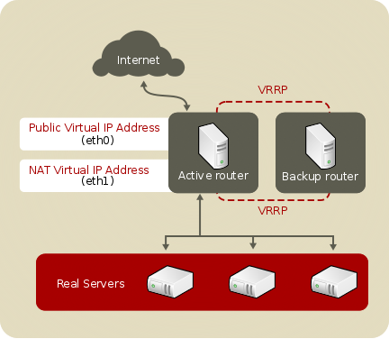
Figure 2.3. Load Balancer Implemented with NAT Routing
In the example, there are two NICs in the active LVS router. The NIC for the Internet has a real IP address and a floating IP address on eth0. The NIC for the private network interface has a real IP address and a floating IP address on eth1. In the event of failover, the virtual interface facing the Internet and the private facing virtual interface are taken over by the backup LVS router simultaneously. All of the real servers located on the private network use the floating IP for the NAT router as their default route to communicate with the active LVS router so that their abilities to respond to requests from the Internet is not impaired.
In this example, the LVS router's public floating IP address and private NAT floating IP address are assigned to physical NICs. While it is possible to associate each floating IP address to its own physical device on the LVS router nodes, having more than two NICs is not a requirement.
Using this topology, the active LVS router receives the request and routes it to the appropriate server. The real server then processes the request and returns the packets to the LVS router which uses network address translation to replace the address of the real server in the packets with the LVS router's public VIP address. This process is called IP masquerading because the actual IP addresses of the real servers is hidden from the requesting clients.
Using this NAT routing, the real servers may be any kind of machine running various operating systems. The main disadvantage is that the LVS router may become a bottleneck in large cluster deployments because it must process outgoing as well as incoming requests.
The
ipvs modules utilize their own internal NAT routines that are independent of iptables and ip6tables NAT. This will facilitate both IPv4 and IPv6 NAT when the real server is configured for NAT as opposed to DR in the /etc/keepalived/keepalived.conf file.
2.4.2. Direct Routing
Building a Load Balancer setup that uses direct routing provides increased performance benefits compared to other Load Balancer networking topologies. Direct routing allows the real servers to process and route packets directly to a requesting user rather than passing all outgoing packets through the LVS router. Direct routing reduces the possibility of network performance issues by relegating the job of the LVS router to processing incoming packets only.

Figure 2.4. Load Balancer Implemented with Direct Routing
In the typical direct routing Load Balancer setup, the LVS router receives incoming server requests through the virtual IP (VIP) and uses a scheduling algorithm to route the request to the real servers. The real server processes the request and sends the response directly to the client, bypassing the LVS router. This method of routing allows for scalability in that real servers can be added without the added burden on the LVS router to route outgoing packets from the real server to the client, which can become a bottleneck under heavy network load.
2.4.2.1. Direct Routing and the ARP Limitation
While there are many advantages to using direct routing in Load Balancer, there are limitations as well. The most common issue with Load Balancer through direct routing is with Address Resolution Protocol (ARP).
In typical situations, a client on the Internet sends a request to an IP address. Network routers typically send requests to their destination by relating IP addresses to a machine's MAC address with ARP. ARP requests are broadcast to all connected machines on a network, and the machine with the correct IP/MAC address combination receives the packet. The IP/MAC associations are stored in an ARP cache, which is cleared periodically (usually every 15 minutes) and refilled with IP/MAC associations.
The issue with ARP requests in a direct routing Load Balancer setup is that because a client request to an IP address must be associated with a MAC address for the request to be handled, the virtual IP address of the Load Balancer system must also be associated to a MAC as well. However, since both the LVS router and the real servers all have the same VIP, the ARP request will be broadcast to all the machines associated with the VIP. This can cause several problems, such as the VIP being associated directly to one of the real servers and processing requests directly, bypassing the LVS router completely and defeating the purpose of the Load Balancer setup.
To solve this issue, ensure that the incoming requests are always sent to the LVS router rather than one of the real servers. This can be done by either filtering ARP requests or filtering IP packets. ARP filtering can be done using the
arptables utility and IP packets can be filtered using iptables or firewalld. The two approaches differ as follows:
- The ARP filtering method blocks requests reaching the real servers. This prevents ARP from associating VIPs with real servers, leaving the active virtual server to respond with a MAC addresses.
- The IP packet filtering method permits routing packets to real servers with other IP addresses. This completely sidesteps the ARP problem by not configuring VIPs on real servers in the first place.
2.5. Persistence and Firewall Marks with Keepalived
In certain situations, it may be desirable for a client to reconnect repeatedly to the same real server, rather than have a load balancing algorithm send that request to the best available server. Examples of such situations include multi-screen web forms, cookies, SSL, and FTP connections. In these cases, a client may not work properly unless the transactions are being handled by the same server to retain context. Keepalived provides two different features to handle this: persistence and firewall marks.
2.5.1. Persistence
When enabled, persistence acts like a timer. When a client connects to a service, Load Balancer remembers the last connection for a specified period of time. If that same client IP address connects again within that period, it is sent to the same server it connected to previously — bypassing the load-balancing mechanisms. When a connection occurs outside the time window, it is handled according to the scheduling rules in place.
Persistence also allows the administrator to specify a subnet mask to apply to the client IP address test as a tool for controlling what addresses have a higher level of persistence, thereby grouping connections to that subnet.
Grouping connections destined for different ports can be important for protocols which use more than one port to communicate, such as FTP. However, persistence is not the most efficient way to deal with the problem of grouping together connections destined for different ports. For these situations, it is best to use firewall marks.
2.5.2. Firewall Marks
Firewall marks are an easy and efficient way to group ports used for a protocol or group of related protocols. For instance, if Load Balancer is deployed to run an e-commerce site, firewall marks can be used to bundle HTTP connections on port 80 and secure, HTTPS connections on port 443. By assigning the same firewall mark to the virtual server for each protocol, state information for the transaction can be preserved because the LVS router forwards all requests to the same real server after a connection is opened.
Because of its efficiency and ease-of-use, administrators of Load Balancer should use firewall marks instead of persistence whenever possible for grouping connections. However, administrators should still add persistence to the virtual servers in conjunction with firewall marks to ensure the clients are reconnected to the same server for an adequate period of time.
Chapter 3. Setting Up Load Balancer Prerequisites for Keepalived
Load Balancer using
keepalived consists of two basic groups: the LVS routers and the real servers. To prevent a single point of failure, each group should have at least two members.
The LVS router group should consist of two identical or very similar systems running Red Hat Enterprise Linux. One will act as the active LVS router while the other stays in hot standby mode, so they need to have as close to the same capabilities as possible.
Before choosing and configuring the hardware for the real server group, determine which of the three Load Balancer topologies to use.
3.1. The NAT Load Balancer Network
The NAT topology allows for great latitude in utilizing existing hardware, but it is limited in its ability to handle large loads because all packets going into and coming out of the pool pass through the Load Balancer router.
- Network Layout
- The topology for Load Balancer using NAT routing is the easiest to configure from a network layout perspective because only one access point to the public network is needed. The real servers are on a private network and respond to all requests through the LVS router.
- Hardware
- In a NAT topology, each real server only needs one NIC since it will only be responding to the LVS router. The LVS routers, on the other hand, need two NICs each to route traffic between the two networks. Because this topology creates a network bottleneck at the LVS router, Gigabit Ethernet NICs can be employed on each LVS router to increase the bandwidth the LVS routers can handle. If Gigabit Ethernet is employed on the LVS routers, any switch connecting the real servers to the LVS routers must have at least two Gigabit Ethernet ports to handle the load efficiently.
- Software
- Because the NAT topology requires the use of
iptablesfor some configurations, there can be a large amount of software configuration outside of Keepalived. In particular, FTP services and the use of firewall marks requires extra manual configuration of the LVS routers to route requests properly.
3.1.1. Configuring Network Interfaces for Load Balancer with NAT
To set up Load Balancer with NAT, you must first configure the network interfaces for the public network and the private network on the LVS routers. In this example, the LVS routers' public interfaces (
eth0) will be on the 203.0.113.0/24 network and the private interfaces which link to the real servers (eth1) will be on the 10.11.12.0/24 network.
Important
At the time of writing, the
NetworkManager service is not compatible with Load Balancer. In particular, IPv6 VIPs are known not to work when the IPv6 addresses are assigned by SLAAC. For this reason, the examples shown here use configuration files and the network service.
On the active or primary LVS router node, the public interface's network configuration file,
/etc/sysconfig/network-scripts/ifcfg-eth0, could look something like this:
DEVICE=eth0
BOOTPROTO=static
ONBOOT=yes
IPADDR=203.0.113.9
NETMASK=255.255.255.0
GATEWAY=203.0.113.254
The configuration file,
/etc/sysconfig/network-scripts/ifcfg-eth1, for the private NAT interface on the LVS router could look something like this:
DEVICE=eth1
BOOTPROTO=static
ONBOOT=yes
IPADDR=10.11.12.9
NETMASK=255.255.255.0
The VIP address must be different to the static address but in the same range. In this example, the VIP for the LVS router's public interface could be configured to be 203.0.113.10 and the VIP for the private interface can be 10.11.12.10. The VIP addresses are set by the
virtual_ipaddress option in the /etc/keepalived/keepalived.conf file. For more information, see Section 4.1, “A Basic Keepalived configuration”.
Also ensure that the real servers route requests back to the VIP for the NAT interface.
Important
The sample Ethernet interface configuration settings in this section are for the real IP addresses of an LVS router and not the floating IP addresses.
After configuring the primary LVS router node's network interfaces, configure the backup LVS router's real network interfaces (taking care that none of the IP address conflict with any other IP addresses on the network).
Important
Ensure that each interface on the backup node services the same network as the interface on the primary node. For instance, if eth0 connects to the public network on the primary node, it must also connect to the public network on the backup node.
3.1.2. Routing on the Real Servers
The most important thing to remember when configuring the real servers network interfaces in a NAT topology is to set the gateway for the NAT floating IP address of the LVS router. In this example, that address is 10.11.12.10.
Note
Once the network interfaces are up on the real servers, the machines will be unable to ping or connect in other ways to the public network. This is normal. You will, however, be able to ping the real IP for the LVS router's private interface, in this case 10.11.12.9.
The real server's configuration file,
/etc/sysconfig/network-scripts/ifcfg-eth0, file could look similar to this:
DEVICE=eth0
ONBOOT=yes
BOOTPROTO=static
IPADDR=10.11.12.1
NETMASK=255.255.255.0
GATEWAY=10.11.12.10
Warning
If a real server has more than one network interface configured with a
GATEWAY= line, the first one to come up will get the gateway. Therefore if both eth0 and eth1 are configured and eth1 is used for Load Balancer, the real servers may not route requests properly.
It is best to turn off extraneous network interfaces by setting
ONBOOT=no in their network configuration files within the /etc/sysconfig/network-scripts/ directory or by making sure the gateway is correctly set in the interface which comes up first.
3.1.3. Enabling NAT Routing on the LVS Routers
In a simple NAT Load Balancer configuration where each clustered service uses only one port, like HTTP on port 80, the administrator need only enable packet forwarding on the LVS routers for the requests to be properly routed between the outside world and the real servers. However, more configuration is necessary when the clustered services require more than one port to go to the same real server during a user session.
Once forwarding is enabled on the LVS routers and the real servers are set up and have the clustered services running, use
keepalived to configure IP information.
Warning
Do not configure the floating IP for
eth0 or eth1 by manually editing network configuration files or using a network configuration tool. Instead, configure them by means of the keepalived.conf file.
When finished, start the
keepalived service. Once it is up and running, the active LVS router will begin routing requests to the pool of real servers.
3.2. Load Balancer Using Direct Routing
Direct routing allows real servers to process and route packets directly to a requesting user rather than passing outgoing packets through the LVS router. Direct routing requires that the real servers be physically connected to a network segment with the LVS router and be able to process and direct outgoing packets as well.
- Network Layout
- In a direct routing Load Balancer setup, the LVS router needs to receive incoming requests and route them to the proper real server for processing. The real servers then need to directly route the response to the client. So, for example, if the client is on the Internet, and sends the packet through the LVS router to a real server, the real server must be able to connect directly to the client through the Internet. This can be done by configuring a gateway for the real server to pass packets to the Internet. Each real server in the server pool can have its own separate gateway (and each gateway with its own connection to the Internet), allowing for maximum throughput and scalability. For typical Load Balancer setups, however, the real servers can communicate through one gateway (and therefore one network connection).
- Hardware
- The hardware requirements of a Load Balancer system using direct routing is similar to other Load Balancer topologies. While the LVS router needs to be running Red Hat Enterprise Linux to process the incoming requests and perform load-balancing for the real servers, the real servers do not need to be Linux machines to function correctly. The LVS routers need one or two NICs each (depending on if there is a backup router). You can use two NICs for ease of configuration and to distinctly separate traffic; incoming requests are handled by one NIC and routed packets to real servers on the other.Since the real servers bypass the LVS router and send outgoing packets directly to a client, a gateway to the Internet is required. For maximum performance and availability, each real server can be connected to its own separate gateway which has its own dedicated connection to the network to which the client is connected (such as the Internet or an intranet).
- Software
- There is some configuration outside of keepalived that needs to be done, especially for administrators facing ARP issues when using Load Balancer by means of direct routing. Refer to Section 3.2.1, “Direct Routing Using arptables” or Section 3.2.3, “Direct Routing Using iptables” for more information.
3.2.1. Direct Routing Using arptables
In order to configure direct routing using
arptables, each real server must have their virtual IP address configured, so they can directly route packets. ARP requests for the VIP are ignored entirely by the real servers, and any ARP packets that might otherwise be sent containing the VIPs are mangled to contain the real server's IP instead of the VIPs.
Using the
arptables method, applications may bind to each individual VIP or port that the real server is servicing. For example, the arptables method allows multiple instances of Apache HTTP Server to be running and bound explicitly to different VIPs on the system.
However, using the
arptables method, VIPs cannot be configured to start on boot using standard Red Hat Enterprise Linux system configuration tools.
To configure each real server to ignore ARP requests for each virtual IP addresses, perform the following steps:
- Create the ARP table entries for each virtual IP address on each real server (the real_ip is the IP the director uses to communicate with the real server; often this is the IP bound to
eth0):arptables -A IN -d <virtual_ip> -j DROP arptables -A OUT -s <virtual_ip> -j mangle --mangle-ip-s <real_ip>
This will cause the real servers to ignore all ARP requests for the virtual IP addresses, and change any outgoing ARP responses which might otherwise contain the virtual IP so that they contain the real IP of the server instead. The only node that should respond to ARP requests for any of the VIPs is the current active LVS node. - Once this has been completed on each real server, save the ARP table entries by typing the following commands on each real server:
arptables-save > /etc/sysconfig/arptablessystemctl enable arptables.serviceThesystemctl enablecommand will cause the system to reload the arptables configuration on bootup before the network is started. - Configure the virtual IP address on all real servers using
ip addrto create an IP alias. For example:#
ip addr add 192.168.76.24 dev eth0 - Configure Keepalived for Direct Routing. This can be done by adding
lb_kind DRto thekeepalived.conffile. Refer to Chapter 4, Initial Load Balancer Configuration with Keepalived for more information.
3.2.2. Direct Routing Using firewalld
You may also work around the ARP issue using the direct routing method by creating firewall rules using
firewalld. To configure direct routing using firewalld, you must add rules that create a transparent proxy so that a real server will service packets sent to the VIP address, even though the VIP address does not exist on the system.
The
firewalld method is simpler to configure than the arptables method. This method also circumvents the LVS ARP issue entirely, because the virtual IP address or addresses exist only on the active LVS director.
However, there are performance issues using the
firewalld method compared to arptables, as there is overhead in forwarding every return packet.
You also cannot reuse ports using the
firewalld method. For example, it is not possible to run two separate Apache HTTP Server services bound to port 80, because both must bind to INADDR_ANY instead of the virtual IP addresses.
To configure direct routing using the
firewalld method, perform the following steps on every real server:
- Ensure that
firewalldis running.#
systemctl start firewalldEnsure thatfirewalldis enabled to start at system start.#
systemctl enable firewalld - Enter the following command for every VIP, port, and protocol (TCP or UDP) combination intended to be serviced for the real server. This command will cause the real servers to process packets destined for the VIP and port that they are given.
#
firewall-cmd --permanent --direct --add-rule ipv4 nat PREROUTING 0 -d vip -p tcp|udp -m tcp|udp --dport port -j REDIRECT - Reload the firewall rules and keep the state information.
#
firewall-cmd --reloadThe current permanent configuration will become the newfirewalldruntime configuration as well as the configuration at the next system start.
3.2.3. Direct Routing Using iptables
You may also work around the ARP issue using the direct routing method by creating
iptables firewall rules. To configure direct routing using iptables, you must add rules that create a transparent proxy so that a real server will service packets sent to the VIP address, even though the VIP address does not exist on the system.
The
iptables method is simpler to configure than the arptables method. This method also circumvents the LVS ARP issue entirely, because the virtual IP address(es) only exist on the active LVS director.
However, there are performance issues using the
iptables method compared to arptables, as there is overhead in forwarding/masquerading every packet.
You also cannot reuse ports using the
iptables method. For example, it is not possible to run two separate Apache HTTP Server services bound to port 80, because both must bind to INADDR_ANY instead of the virtual IP addresses.
To configure direct routing using the
iptables method, perform the following steps:
- On each real server, enter the following command for every VIP, port, and protocol (TCP or UDP) combination intended to be serviced for the real server:
iptables -t nat -A PREROUTING -p <tcp|udp> -d <vip> --dport <port> -j REDIRECTThis command will cause the real servers to process packets destined for the VIP and port that they are given. - Save the configuration on each real server:
#
iptables-save > /etc/sysconfig/iptables#systemctl enable iptables.serviceThesystemctl enablecommand will cause the system to reload the iptables configuration on bootup before the network is started.
3.2.4. Direct Routing Using sysctl
Another way to deal with the ARP limitation when employing Direct Routing is using the
sysctl interface. Administrators can configure two systcl settings such that the real server will not announce the VIP in ARP requests and will not reply to ARP requests for the VIP address. To enable this, enter the following commands:
echo 1 > /proc/sys/net/ipv4/conf/eth0/arp_ignore
echo 2 > /proc/sys/net/ipv4/conf/eth0/arp_announce
Alternatively, you may add the following lines to the
/etc/sysctl.d/arp.conf file:
net.ipv4.conf.eth0.arp_ignore = 1
net.ipv4.conf.eth0.arp_announce = 2
3.3. Putting the Configuration Together
After determining which of the preceding routing methods to use, the hardware should be connected together and configured.
Important
The network adapters on the LVS routers must be configured to access the same networks. For instance if
eth0 connects to the public network and eth1 connects to the private network, then these same devices on the backup LVS router must connect to the same networks.
Also the gateway listed in the first interface to come up at boot time is added to the routing table and subsequent gateways listed in other interfaces are ignored. This is especially important to consider when configuring the real servers.
After connecting the hardware to the network, configure the network interfaces on the primary and backup LVS routers. This should be done by editing the network configuration files manually. For more information about working with network configuration files, see the Red Hat Enterprise Linux 7 Networking Guide.
3.3.1. General Load Balancer Networking Tips
Configure the real IP addresses for both the public and private networks on the LVS routers before attempting to configure Load Balancer using Keepalived. The sections on each topology give example network addresses, but the actual network addresses are needed. Below are some useful commands for bringing up network interfaces or checking their status.
- Bringing Up Real Network Interfaces
- To open a real network interface, use the following command as
root, replacing N with the number corresponding to the interface (eth0andeth1).ifup ethNWarning
Do not use theifupscripts to open any floating IP addresses you may configure using Keepalived (eth0:1oreth1:1). Use theserviceorsystemctlcommand to startkeepalivedinstead. - Bringing Down Real Network Interfaces
- To bring down a real network interface, use the following command as
root, replacing N with the number corresponding to the interface (eth0andeth1).ifdown ethN - Checking the Status of Network Interfaces
- If you need to check which network interfaces are up at any given time, enter the following command:
ip linkTo view the routing table for a machine, issue the following command:ip route
3.3.2. Firewall Requirements
If you are running a firewall (by means of
firewalld or iptables), you must allow VRRP traffic to pass between the keepalived nodes. To configure the firewall to allow the VRRP traffic with firewalld, run the following commands:
#firewall-cmd --add-rich-rule='rule protocol value="vrrp" accept' --permanent#firewall-cmd --reload
If the zone is omitted the default zone will be used.
If, however, you need to allow the VRRP traffic with
iptables, run the following commands:
#iptables -I INPUT -p vrrp -j ACCEPT#iptables-save > /etc/sysconfig/iptables#systemctl restart iptables
3.4. Multi-port Services and Load Balancer
LVS routers under any topology require extra configuration when creating multi-port Load Balancer services. Multi-port services can be created artificially by using firewall marks to bundle together different, but related protocols, such as HTTP (port 80) and HTTPS (port 443), or when Load Balancer is used with true multi-port protocols, such as FTP. In either case, the LVS router uses firewall marks to recognize that packets destined for different ports, but bearing the same firewall mark, should be handled identically. Also, when combined with persistence, firewall marks ensure connections from the client machine are routed to the same host, as long as the connections occur within the length of time specified by the persistence parameter.
Although the mechanism used to balance the loads on the real servers, IPVS, can recognize the firewall marks assigned to a packet, it cannot itself assign firewall marks. The job of assigning firewall marks must be performed by the network packet filter,
iptables. The default firewall administration tool in Red Hat Enterprise Linux 7 is firewalld, which can be used to configure iptables. If preferred, iptables can be used directly. See Red Hat Enterprise Linux 7 Security Guide for information on working with iptables in Red Hat Enterprise Linux 7.
3.4.1. Assigning Firewall Marks Using firewalld
To assign firewall marks to a packet destined for a particular port, the administrator can use
firewalld's firewall-cmd utility.
If required, confirm that
firewalld is running:
# systemctl status firewalld
firewalld.service - firewalld - dynamic firewall daemon
   Loaded: loaded (/usr/lib/systemd/system/firewalld.service; enabled)
   Active: active (running) since Tue 2016-01-26 05:23:53 EST; 7h ago
To start firewalld, enter:
# systemctl start firewalld
To ensure firewalld is enabled to start at system start:
# systemctl enable firewalld
This section illustrates how to bundle HTTP and HTTPS as an example; however, FTP is another commonly clustered multi-port protocol.
The basic rule to remember when using firewall marks is that for every protocol using a firewall mark in Keepalived there must be a commensurate firewall rule to assign marks to the network packets.
Before creating network packet filter rules, make sure there are no rules already in place. To do this, open a shell prompt, login as
root, and enter the following command:
# firewall-cmd --list-rich-rules
If no rich rules are present the prompt will instantly reappear.
If
firewalld is active and rich rules are present, it displays a set of rules.
If the rules already in place are important, check the contents of
/etc/firewalld/zones/ and copy any rules worth keeping to a safe place before proceeding. Delete unwanted rich rules using a command in the following format: firewall-cmd --zone=zone --remove-rich-rule='rule' --permanentThe
--permanent option makes the setting persistent, but the command will only take effect at next system start. If required to make the setting take effect immediately, repeat the command omitting the --permanent option.
The first load balancer related firewall rule to be configured is to allow VRRP traffic for the Keepalived service to function. Enter the following command:
# firewall-cmd --add-rich-rule='rule protocol value="vrrp" accept' --permanent
If the zone is omitted the default zone will be used.
Below are rules which assign the same firewall mark,
80, to incoming traffic destined for the floating IP address, n.n.n.n, on ports 80 and 443.
#firewall-cmd --add-rich-rule='rule family="ipv4" destination address="n.n.n.n/32" port port="80" protocol="tcp" mark set="80"' --permanent#firewall-cmd --add-rich-rule='rule family="ipv4" destination address="n.n.n.n/32" port port="443" protocol="tcp" mark set="80"' --permanent#firewall-cmd --reloadsuccess #firewall-cmd --list-rich-rulesrule protocol value="vrrp" accept rule family="ipv4" destination address="n.n.n.n/32" port port="80" protocol="tcp" mark set=80 rule family="ipv4" destination address="n.n.n.n/32" port port="443" protocol="tcp" mark set=80
If the zone is omitted the default zone will be used.
See the Red Hat Enterprise Linux 7 Security Guide for more information on the use of
firewalld's rich language commands.
3.4.2. Assigning Firewall Marks Using iptables
To assign firewall marks to a packet destined for a particular port, the administrator can use
iptables.
This section illustrates how to bundle HTTP and HTTPS as an example; however, FTP is another commonly clustered multi-port protocol.
The basic rule to remember when using firewall marks is that for every protocol using a firewall mark in Keepalived there must be a commensurate firewall rule to assign marks to the network packets.
Before creating network packet filter rules, make sure there are no rules already in place. To do this, open a shell prompt, login as
root, and enter the following command:
/usr/sbin/service iptables status
If
iptables is not running, the prompt will instantly reappear.
If
iptables is active, it displays a set of rules. If rules are present, enter the following command:
/sbin/service iptables stop
If the rules already in place are important, check the contents of
/etc/sysconfig/iptables and copy any rules worth keeping to a safe place before proceeding.
The first load balancer related configuring firewall rules is to allow VRRP traffic for the Keepalived service to function.
/usr/sbin/iptables -I INPUT -p vrrp -j ACCEPT
Below are rules which assign the same firewall mark,
80, to incoming traffic destined for the floating IP address, n.n.n.n, on ports 80 and 443.
/usr/sbin/iptables -t mangle -A PREROUTING -p tcp -d n.n.n.n/32 -m multiport --dports 80,443 -j MARK --set-mark 80
Note that you must log in as
root and load the module for iptables before issuing rules for the first time.
In the above
iptables commands, n.n.n.n should be replaced with the floating IP for your HTTP and HTTPS virtual servers. These commands have the net effect of assigning any traffic addressed to the VIP on the appropriate ports a firewall mark of 80, which in turn is recognized by IPVS and forwarded appropriately.
Warning
The commands above will take effect immediately, but do not persist through a reboot of the system.
3.5. Configuring FTP
File Transport Protocol (FTP) is an old and complex multi-port protocol that presents a distinct set of challenges to an Load Balancer environment. To understand the nature of these challenges, you must first understand some key things about how FTP works.
3.5.1. How FTP Works
With most other server client relationships, the client machine opens up a connection to the server on a particular port and the server then responds to the client on that port. When an FTP client connects to an FTP server it opens a connection to the FTP control port 21. Then the client tells the FTP server whether to establish an active or passive connection. The type of connection chosen by the client determines how the server responds and on what ports transactions will occur.
The two types of data connections are:
- Active Connections
- When an active connection is established, the server opens a data connection to the client from port 20 to a high range port on the client machine. All data from the server is then passed over this connection.
- Passive Connections
- When a passive connection is established, the client asks the FTP server to establish a passive connection port, which can be on any port higher than 10,000. The server then binds to this high-numbered port for this particular session and relays that port number back to the client. The client then opens the newly bound port for the data connection. Each data request the client makes results in a separate data connection. Most modern FTP clients attempt to establish a passive connection when requesting data from servers.
Note
The client determines the type of connection, not the server. This means to effectively cluster FTP, you must configure the LVS routers to handle both active and passive connections.
The FTP client-server relationship can potentially open a large number of ports that Keepalived does not know about.
3.5.2. How This Affects Load Balancer Routing
IPVS packet forwarding only allows connections in and out of the cluster based on it recognizing its port number or its firewall mark. If a client from outside the cluster attempts to open a port IPVS is not configured to handle, it drops the connection. Similarly, if the real server attempts to open a connection back out to the Internet on a port IPVS does not know about, it drops the connection. This means all connections from FTP clients on the Internet must have the same firewall mark assigned to them and all connections from the FTP server must be properly forwarded to the Internet using network packet filtering rules.
Note
In order to enable passive FTP connections, you must have the
ip_vs_ftp kernel module loaded. Run the following commands as an administrative user at a shell prompt to load this module and and ensure that the module loads on a reboot:
echo "ip_vs_ftp" >> /etc/modules-load.d/ip_vs_ftp.conf
systemctl enable systemd-modules-load
systemctl start systemd-modules-load
3.5.3. Creating Network Packet Filter Rules
Before assigning any
iptables rules for the FTP service, review the information in Section 3.4, “Multi-port Services and Load Balancer ” concerning multi-port services and techniques for checking the existing network packet filtering rules.
Below are rules which assign the same firewall mark,
21, to FTP traffic.
3.5.3.1. Rules for Active Connections
The rules for active connections tell the kernel to accept and forward connections coming to the internal floating IP address on port
20 (the FTP data port).
The following
iptables command allows the LVS router to accept outgoing connections from the real servers that IPVS does not know about:
/usr/sbin/iptables -t nat -A POSTROUTING -p tcp -s n.n.n.0/24 --sport 20 -j MASQUERADE
In the
iptables command, n.n.n should be replaced with the first three values for the floating IP for the NAT interface's internal network interface defined virtual_server section of the keepalived.conf file.
3.5.3.2. Rules for Passive Connections
The rules for passive connections assign the appropriate firewall mark to connections coming in from the Internet to the floating IP address for the service on a wide range of ports: 10,000 to 20,000.
Warning
If you are limiting the port range for passive connections, you must also configure the FTP server,
vsftpd, to use a matching port range. This can be accomplished by adding the following lines to /etc/vsftpd.conf:
pasv_min_port=10000
pasv_max_port=20000
Setting
pasv_address to override the real FTP server address should not be used since it is updated to the virtual IP address by LVS.
For configuration of other FTP servers, consult the respective documentation.
This range should be a wide enough for most situations; however, you can increase this number to include all available non-secured ports by changing
10000:20000 in the commands below to 1024:65535.
The following
iptables commands have the net effect of assigning any traffic addressed to the floating IP on the appropriate ports a firewall mark of 21, which is in turn recognized by IPVS and forwarded appropriately:
/usr/sbin/iptables -t mangle -A PREROUTING -p tcp -d n.n.n.n/32 --dport 21 -j MARK --set-mark 21
/usr/sbin/iptables -t mangle -A PREROUTING -p tcp -d n.n.n.n/32 --dport 10000:20000 -j MARK --set-mark 21
In the
iptables commands, n.n.n.n should be replaced with the floating IP for the FTP virtual server defined in the virtual_server subsection of the keepalived.conf file.
The commands above take effect immediately, but do not persist through a reboot of the system unless they are saved. To save the changes, enter the following command:
# iptables-save > /etc/sysconfig/iptables
To ensure the
iptables service is started at system start, enter the following command:
# systemctl enable iptables
You can verify whether the changes persist on a reboot by running the following command and checking whether the changes remain:
# systemctl restart iptables3.6. Saving Network Packet Filter Settings
After configuring the appropriate network packet filters for your situation, save the settings so they can be restored after a reboot. For
iptables, enter the following command:
# iptables-save > /etc/sysconfig/iptables
To ensure the
iptables service is started at system start, enter the following command:
# systemctl enable iptables
You can verify whether the changes persist on a reboot by running the following command and checking whether the changes remain:
# systemctl restart iptables
See the Red Hat Enterprise Linux 7 Security Guide for more information on working with iptables in Red Hat Enterprise Linux 7
3.7. Turning on Packet Forwarding and Nonlocal Binding
In order for the Keepalived service to forward network packets properly to the real servers, each router node must have IP forwarding turned on in the kernel. Log in as
root and change the line which reads net.ipv4.ip_forward = 0 in /etc/sysctl.conf to the following:
net.ipv4.ip_forward = 1
The changes take effect when you reboot the system.
Load balancing in HAProxy and Keepalived at the same time also requires the ability to bind to an IP address that are nonlocal, meaning that it is not assigned to a device on the local system. This allows a running load balancer instance to bind to an IP that is not local for failover.
To enable, edit the line in
/etc/sysctl.conf that reads net.ipv4.ip_nonlocal_bind to the following:
net.ipv4.ip_nonlocal_bind = 1
The changes take effect when you reboot the system.
To check if IP forwarding is turned on, issue the following command as
root:
/usr/sbin/sysctl net.ipv4.ip_forward
To check if nonlocal binding is turned on, issue the following command as
root:
/usr/sbin/sysctl net.ipv4.ip_nonlocal_bind
If both the above commands return a
1, then the respective settings are enabled.
3.8. Configuring Services on the Real Servers
If the real servers are Red Hat Enterprise Linux systems, set the appropriate server daemons to activate at boot time. These daemons can include
httpd for Web services or xinetd for FTP or Telnet services.
It may also be useful to access the real servers remotely, so the
sshd daemon should also be installed and running.
Chapter 4. Initial Load Balancer Configuration with Keepalived
After installing Load Balancer packages, you must take some basic steps to set up the LVS router and the real servers for use with Keepalived. This chapter covers these initial steps in detail.
4.1. A Basic Keepalived configuration
In this basic example, two systems are configured as load balancers. LB1 (Active) and LB2 (Backup) will be routing requests for a pool of four Web servers running
httpd with real IP addresses numbered 192.168.1.20 to 192.168.1.24, sharing a virtual IP address of 10.0.0.1. Each load balancer has two interfaces (eth0 and eth1), one for handling external Internet traffic, and the other for routing requests to the real servers. The load balancing algorithm used is Round Robin and the routing method will be Network Address Translation.
4.1.1. Creating the keapalived.conf file
Keepalived is configured by means of the
keepalived.conf file in each system configured as a load balancer. To create a load balancer topology like the example shown in Section 4.1, “A Basic Keepalived configuration”, use a text editor to open keepalived.conf in both the active and backup load balancers, LB1 and LB2. For example:
vi /etc/keepalived/keepalived.conf
A basic load balanced system with the configuration as detailed in Section 4.1, “A Basic Keepalived configuration” has a
keepalived.conf file as explained in the following code sections. In this example, the keepalived.conf file is the same on both the active and backup routers with the exception of the VRRP instance, as noted in Section 4.1.1.2, “VRRP Instance”
4.1.1.1. Global Definitions
The Global Definitions section of the
keepalived.conf file allows administrators to specify notification details when changes to the load balancer occurs. Note that the Global Definitions are optional and are not required for Keepalived configuration. This section of the keepalived.conf file is the same on both LB1 and LB2.
global_defs {

   notification_email {
       admin@example.com
   }
   notification_email_from noreply@example.com
   smtp_server 127.0.0.1
   smtp_connect_timeout 60
}
The
notification_email is the administrator of the load balancer, while the notification_email_from is an address that sends the load balancer state changes. The SMTP specific configuration specifies the mail server from which the notifications are mailed.
4.1.1.2. VRRP Instance
The following examples show the
vrrp_sync_group stanza of the keeplalived.conf file in the master router and the backup router. Note that the state and priority values differ between the two systems.
The following example shows the
vrrp_sync_group stanza for the keepalived.conf file in LB1, the master router.
vrrp_sync_group VG1 {
   group {
      RH_EXT
      RH_INT
   }
}

vrrp_instance RH_EXT {
    state MASTER
    interface eth0
    virtual_router_id 50
    priority 100
    advert_int 1
    authentication {
        auth_type PASS
        auth_pass passw123
    }
    virtual_ipaddress {
    10.0.0.1
    }
}

vrrp_instance RH_INT {
   state MASTER
   interface eth1
   virtual_router_id 2
   priority 100
   advert_int 1
   authentication {
       auth_type PASS
       auth_pass passw123
   }
   virtual_ipaddress {
       192.168.1.1
   }
}
The following example shows the
vrrp_sync_group stanza of the keepalived.conf file for LB2, the backup router.
vrrp_sync_group VG1 {
   group {
      RH_EXT
      RH_INT
   }
}

vrrp_instance RH_EXT {
    state BACKUP
    interface eth0
    virtual_router_id 50
    priority 99
    advert_int 1
    authentication {
        auth_type PASS
        auth_pass passw123
    }
    virtual_ipaddress {
    10.0.0.1
    }
}

vrrp_instance RH_INT {
   state BACKUP
   interface eth1
   virtual_router_id 2
   priority 99
   advert_int 1
   authentication {
       auth_type PASS
       auth_pass passw123
   }
   virtual_ipaddress {
       192.168.1.1
   }
}
In these example, the
vrrp_sync_group stanza defines the VRRP group that stays together through any state changes (such as failover). There is an instance defined for the external interface that communicates with the Internet (RH_EXT), as well as one for the internal interface (RH_INT).
The
vrrp_instance line details the virtual interface configuration for the VRRP service daemon, which creates virtual IP instances. The state MASTER designates the active server, the state BACKUP designates the backup server.
The
interface parameter assigns the physical interface name to this particular virtual IP instance.
virtual_router_id is a numerical identifier for the Virtual Router instance. It must be the same on all LVS Router systems participating in this Virtual Router. It is used to differentiate multiple instances of keepalived running on the same network interface.
The
priority specifies the order in which the assigned interface takes over in a failover; the higher the number, the higher the priority. This priority value must be within the range of 0 to 255, and the Load Balancing server configured as state MASTER should have a priority value set to a higher number than the priority value of the server configured as state BACKUP.
The
authentication block specifies the authentication type (auth_type) and password (auth_pass) used to authenticate servers for failover synchronization. PASS specifies password authentication; Keepalived also supports AH, or Authentication Headers for connection integrity.
Finally, the
virtual_ipaddress option specifies the interface virtual IP address.
4.1.1.3. Virtual Server Definitions
The Virtual Server definitions section of the
keepalived.conf file is the same on both LB1 and LB2.
virtual_server 10.0.0.1 80 {
    delay_loop 6
    lb_algo rr
    lb_kind NAT
    protocol TCP

    real_server 192.168.1.20 80 {
        TCP_CHECK {
                connect_timeout 10
        }
    }
    real_server 192.168.1.21 80 {
        TCP_CHECK {
                connect_timeout 10
        }
    }
    real_server 192.168.1.22 80 {
        TCP_CHECK {
                connect_timeout 10
        }
    }
    real_server 192.168.1.23 80 {
        TCP_CHECK {
                connect_timeout 10
        }
    }

}
In this block, the
virtual_server is configured first with the IP address. Then a delay_loop configures the amount of time (in seconds) between health checks. The lb_algo option specifies the kind of algorithm used for availability (in this case, rr for Round-Robin; for a list of possible lb_algo values see Table 4.1, “lv_algo Values for Virtual Server”). The lb_kind option determines routing method, which in this case Network Address Translation (or nat) is used.
After configuring the Virtual Server details, the
real_server options are configured, again by specifying the IP Address first. The TCP_CHECK stanza checks for availability of the real server using TCP. The connect_timeout configures the time in seconds before a timeout occurs.
Note
Accessing the virtual IP from the load balancers or one of the real servers is not supported. Likewise, configuring a load balancer on the same machines as a real server is not supported.
| Algorithm Name | lv_algo value |
|---|---|
|
Round-Robin
| rr
|
|
Weighted Round-Robin
| wrr
|
|
Least-Connection
| lc
|
|
Weighted Least-Connection
| wlc
|
|
Locality-Based Least-Connection
| lblc
|
|
Locality-Based Least-Connection Scheduling with Replication
| lblcr
|
|
Destination Hash
| dh
|
|
Source Hash
| sh
|
|
Source Expected Delay
| sed
|
|
Never Queue
| nq
|
4.2. Keepalived Direct Routing Configuration
Direct Routing configuration of Keepalived is similar in configuration with NAT. In the following example, Keepalived is configured to provide load balancing for a group of real servers running HTTP on port 80. To configure Direct Routing, change the
lb_kind parameter to DR. Other configuration options are discussed in Section 4.1, “A Basic Keepalived configuration”.
The following example shows the
keepalived.conf file for the active server in a Keepalived configuration that uses direct routing.
global_defs {
   notification_email {
     admin@example.com
   }
   notification_email_from noreply_admin@example.com
   smtp_server 127.0.0.1
   smtp_connect_timeout 60
}

vrrp_instance RH_1 {
    state MASTER
    interface eth0
    virtual_router_id 50
    priority 100
    advert_int 1
    authentication {
        auth_type PASS
        auth_pass passw123
    }
    virtual_ipaddress {
        172.31.0.1
    }
}

virtual_server 172.31.0.1 80 {
    delay_loop 10
    lb_algo rr
    lb_kind DR
    persistence_timeout 9600
    protocol TCP

    real_server 192.168.0.1 80 {
        weight 1
        TCP_CHECK {
          connect_timeout 10
          connect_port    80
        }
    }
    real_server 192.168.0.2 80 {
        weight 1
        TCP_CHECK {
          connect_timeout 10
          connect_port    80
        }
    }
    real_server 192.168.0.3 80 {
        weight 1
        TCP_CHECK {
          connect_timeout 10
          connect_port    80
        }
    }
}
The following example shows the
keepalived.conf file for the backup server in a Keepalived configuration that uses direct routing. Note that the state and priority values differ from the keepalived.conf file in the active server.
global_defs {
   notification_email {
     admin@example.com
   }
   notification_email_from noreply_admin@example.com
   smtp_server 127.0.0.1
   smtp_connect_timeout 60
}

vrrp_instance RH_1 {
    state BACKUP
    interface eth0
    virtual_router_id 50
    priority 99
    advert_int 1
    authentication {
        auth_type PASS
        auth_pass passw123
    }
    virtual_ipaddress {
        172.31.0.1
    }
}

virtual_server 172.31.0.1 80 {
    delay_loop 10
    lb_algo rr
    lb_kind DR
    persistence_timeout 9600
    protocol TCP

    real_server 192.168.0.1 80 {
        weight 1
        TCP_CHECK {
          connect_timeout 10
          connect_port    80
        }
    }
    real_server 192.168.0.2 80 {
        weight 1
        TCP_CHECK {
          connect_timeout 10
          connect_port    80
        }
    }
    real_server 192.168.0.3 80 {
        weight 1
        TCP_CHECK {
          connect_timeout 10
          connect_port    80
        }
    }
}
4.3. Starting the service
Start the service by entering the following command on the servers in the load balancer configuration:
# systemctl start keepalived.service
To make Keepalived service persist through reboots, enter the following command on the servers in the load balancer configuration:
# systemctl enable keepalived.serviceChapter 5. HAProxy Configuration
This chapter explains the configuration of a basic setup that highlights the common configuration options an administrator could encounter when deploying HAProxy services for high availability environments.
HAProxy has its own set of scheduling algorithms for load balancing. These algorithms are described in Section 5.1, “HAProxy Scheduling Algorithms”.
HAProxy is configured by editing the
/etc/haproxy/haproxy.cfg file.
Load Balancer configuration using HAProxy consists of five sections for configuration:
- The proxies section, which consists of 4 subsections:
- The Section 5.3, “Default Settings” settings
- The Section 5.4, “Frontend Settings” settings
- The Section 5.5, “Backend Settings” settings
5.1. HAProxy Scheduling Algorithms
The HAProxy scheduling algorithms for load balancing can be edited in the
balance parameter in the backend section of the /etc/haproxy/haproxy.cfg configuration file. Note that HAProxy supports configuration with multiple back ends, and each back end can be configured with a scheduling algorithm.
- Round-Robin (
roundrobin) - Distributes each request sequentially around the pool of real servers. Using this algorithm, all the real servers are treated as equals without regard to capacity or load. This scheduling model resembles round-robin DNS but is more granular due to the fact that it is network-connection based and not host-based. Load Balancer round-robin scheduling also does not suffer the imbalances caused by cached DNS queries. However, in HAProxy, since configuration of server weights can be done on the fly using this scheduler, the number of active servers are limited to 4095 per back end.
- Static Round-Robin (
static-rr) - Distributes each request sequentially around a pool of real servers as does Round-Robin, but does not allow configuration of server weight dynamically. However, because of the static nature of server weight, there is no limitation on the number of active servers in the back end.
- Least-Connection (
leastconn) - Distributes more requests to real servers with fewer active connections. Administrators with a dynamic environment with varying session or connection lengths may find this scheduler a better fit for their environments. It is also ideal for an environment where a group of servers have different capacities, as administrators can adjust weight on the fly using this scheduler.
- Source (
source) - Distributes requests to servers by hashing requesting source IP address and dividing by the weight of all the running servers to determine which server will get the request. In a scenario where all servers are running, the source IP request will be consistently served by the same real server. If there is a change in the number or weight of the running servers, the session may be moved to another server because the hash/weight result has changed.
- URI (
uri) - Distributes requests to servers by hashing the entire URI (or a configurable portion of a URI) and divides by the weight of all the running servers to determine which server will the request. In a scenario where all active servers are running, the destination IP request will be consistently served by the same real server. This scheduler can be further configured by the length of characters at the start of a directory part of a URI to compute the hash result and the depth of directories in a URI (designated by forward slashes in the URI) to compute the hash result.
- URL Parameter (
url_param) - Distributes requests to servers by looking up a particular parameter string in a source URL request and performing a hash calculation divided by the weight of all running servers. If the parameter is missing from the URL, the scheduler defaults to Round-robin scheduling. Modifiers may be used based on POST parameters as well as wait limits based on the number of maximum octets an administrator assigns to the weight for a certain parameter before computing the hash result.
- Header Name (
hdr) - Distributes requests to servers by checking a particular header name in each source HTTP request and performing a hash calculation divided by the weight of all running servers. If the header is absent, the scheduler defaults to Round-robin scheduling.
- RDP Cookie (
rdp-cookie) - Distributes requests to servers by looking up the RDP cookie for every TCP request and performing a hash calculation divided by the weight of all running servers. If the header is absent, the scheduler defaults to Round-robin scheduling. This method is ideal for persistence as it maintains session integrity.
5.2. Global Settings
The
global settings configure parameters that apply to all servers running HAProxy. A typical global section may look like the following:
global
    log 127.0.0.1 local2
    maxconn 4000
    user haproxy
    group haproxy
    daemon
In the above configuration, the administrator has configured the service to
log all entries to the local syslog server. By default, this could be /var/log/syslog or some user-designated location.
The
maxconn parameter specifies the maximum number of concurrent connections for the service. By default, the maximum is 2000.
The
user and group parameters specifies the user name and group name for which the haproxy process belongs.
Finally, the
daemon parameter specifies that haproxy run as a background process.
5.3. Default Settings
The
default settings configure parameters that apply to all proxy subsections in a configuration (frontend, backend, and listen). A typical default section may look like the following:
Note
Any parameter configured in
proxy subsection (frontend, backend, or listen) takes precedence over the parameter value in default.
defaults
    mode                    http
    log                     global
    option                  httplog
    option                  dontlognull
    retries                 3
    timeout http-request    10s
    timeout queue           1m
    timeout connect         10s
    timeout client          1m
    timeout server          1m
mode specifies the protocol for the HAProxy instance. Using the http mode connects source requests to real servers based on HTTP, ideal for load balancing web servers. For other applications, use the tcp mode.
log specifies log address and syslog facilities to which log entries are written. The global value refers the HAProxy instance to whatever is specified in the log parameter in the global section.
option httplog enables logging of various values of an HTTP session, including HTTP requests, session status, connection numbers, source address, and connection timers among other values.
option dontlognull disables logging of null connections, meaning that HAProxy will not log connections wherein no data has been transferred. This is not recommended for environments such as web applications over the Internet where null connections could indicate malicious activities such as open port-scanning for vulnerabilities.
retries specifies the number of times a real server will retry a connection request after failing to connect on the first try.
The various
timeout values specify the length of time of inactivity for a given request, connection, or response. These values are generally expressed in milliseconds (unless explicitly stated otherwise) but may be expressed in any other unit by suffixing the unit to the numeric value. Supported units are us (microseconds), ms (milliseconds), s (seconds), m (minutes), h (hours) and d (days). http-request 10s gives 10 seconds to wait for a complete HTTP request from a client. queue 1m sets one minute as the amount of time to wait before a connection is dropped and a client receives a 503 or "Service Unavailable" error. connect 10s specifies the number of seconds to wait for a successful connection to a server. client 1m specifies the amount of time (in minutes) a client can remain inactive (it neither accepts nor sends data). server 1m specifies the amount of time (in minutes) a server is given to accept or send data before timeout occurs.
5.4. Frontend Settings
The
frontend settings configure the servers' listening sockets for client connection requests. A typical HAProxy configuration of the frontend may look like the following:
frontend  main
  bind 192.168.0.10:80
  default_backend app
The
frontend called main is configured to the 192.168.0.10 IP address and listening on port 80 using the bind parameter. Once connected, the use backend specifies that all sessions connect to the app back end.
5.5. Backend Settings
The
backend settings specify the real server IP addresses as well as the load balancer scheduling algorithm. The following example shows a typical backend section:
backend app
   balance     roundrobin
   server  app1 192.168.1.1:80 check
   server  app2 192.168.1.2:80 check
   server  app3 192.168.1.3:80 check inter 2s rise 4 fall 3
   server  app4 192.168.1.4:80 backup
The back-end server is named
app. The balance specifies the load balancer scheduling algorithm to be used, which in this case is Round Robin (roundrobin), but can be any scheduler supported by HAProxy. For more information configuring schedulers in HAProxy, see Section 5.1, “HAProxy Scheduling Algorithms”.
The
server lines specify the servers available in the back end. app1 to app4 are the names assigned internally to each real server. Log files will specify server messages by name. The address is the assigned IP address. The value after the colon in the IP address is the port number to which the connection occurs on the particular server. The check option flags a server for periodic healthchecks to ensure that it is available and able receive and send data and take session requests. Server app3 also configures the healthcheck interval to two seconds (inter 2s), the amount of checks app3 has to pass to determine if the server is considered healthy (rise 4), and the number of times a server consecutively fails a check before it is considered failed (fall 3).
5.6. Starting haproxy
To start the HAProxy service, enter the following command:
# systemctl start haproxy.service
To make the HAProxy service persist through reboots, enter the following command:
# systemctl enable haproxy.service5.7. Logging HAProxy Messages to rsyslog
You can configure your system to log HAProxy messages to
rsyslog by writing to the /dev/log socket. Alternately you can target the TCP loopback address, however this results in slower performance.
The following procedure configures HAProxy to log messages to
rsyslog.
- In the
globalsection of the HAProxy configuration file, use thelogdirective to target the/dev/logsocket.log /dev/log local0
- Update the
frontend,backend, andlistenproxies to send messages to thersyslogservice you configured in theglobalsection of the HAProxy configuration file. To do this, add alog globaldirective to thedefaultssection of the configuration file, as shown.defaults log global option httplog - If you are running HAProxy within a
chrootedenvironment, or you let HAProxy create achrootdirectory for you by using thechrootconfiguration directive, then the socket must be made available within thatchrootdirectory. You can do this by modifying thersyslogconfiguration to create a new listening socket within thechrootfilesystem. To do this, add the following lines to yourrsyslogconfiguration file.$ModLoad imuxsock $AddUnixListenSocket PATH_TO_CHROOT/dev/log
- To customize what and where HAProxy log messages will appear, you can use
rsyslogfilters as described in Basic Configuration of Rsyslog in the System Administrator's Guide.
Appendix A. Example Configuration: Load Balancing Ceph Object Gateway Servers with HAProxy and Keepalived
This appendix provides an example showing the configuration of HAProxy and Keepalived with a Ceph cluster. The Ceph Object Gateway allows you to assign many instances of the object gateway to a single zone so that you can scale out as load increases. Since each object gateway instance has its own IP address, you can use HAProxy and keepalived to balance the load across Ceph Object Gateway servers.
In this configuration, HAproxy performs the load balancing across Ceph Object Gateway servers while Keepalived is used to manage the Virtual IP addresses of the Ceph Object Gateway servers and to monitor HAProxy.
Another use case for HAProxy and keepalived is to terminate HTTPS at the HAProxy server. Red Hat Ceph Storage (RHCS) 1.3.x uses Civetweb, and the implementation in RHCS 1.3.x does not support HTTPS. You can use an HAProxy server to terminate HTTPS at the HAProxy server and use HTTP between the HAProxy server and the Civetweb gateway instances. This example includes this configuration as part of the procedure.
A.1. Prerequisites
To set up HAProxy with the Ceph Object Gateway, you must have:
- A running Ceph cluster;
- At least two Ceph Object Gateway servers within the same zone configured to run on port 80;
- At least two servers for HAProxy and keepalived.
Note
This procedure assumes that you have at least two Ceph Object Gateway servers running, and that you get a valid response when running test scripts over port 80.
A.2. Preparing HAProxy Nodes
The following setup assumes two HAProxy nodes named
haproxy and haproxy2, and two Ceph Object Gateway servers named rgw1 and rgw2. You may use any naming convention you prefer. Perform the following procedure on your two HAProxy nodes:
- Install Red Hat Enterprise Linux 7.
- Register the nodes.
#
subscription-manager register - Enable the Red Hat Enterprise Linux 7 server repository.
#
subscription-manager repos --enable=rhel-7-server-rpms - Update the server.
#
yum update -y - Install admin tools (for example,
wget,vim, and so on) as needed. - Open port 80.
#
firewall-cmd --zone=public --add-port 80/tcp --permanent#firewall-cmd --reload - For HTTPS, open port 443.
#
firewall-cmd --zone=public --add-port 443/tcp --permanent#firewall-cmd --reload
A.3. Install and Configure keepalived
Perform the following procedure on your two HAProxy nodes:
- Install keepalived.
#
yum install -y keepalived - Configure keepalived.
#
vim /etc/keepalived/keepalived.confIn the following configuration, there is a script to check the HAProxy processes. The instance useseth0as the network interface and configureshaproxyas the master server andhaproxy2as the backup server. It also assigns a virtual IP address of 192.168.0.100.vrrp_script chk_haproxy { script "killall -0 haproxy" # check the haproxy process interval 2 # every 2 seconds weight 2 # add 2 points if OK } vrrp_instance VI_1 { interface eth0 # interface to monitor state MASTER # MASTER on haproxy, BACKUP on haproxy2 virtual_router_id 51 priority 101 # 101 on haproxy, 100 on haproxy2 virtual_ipaddress { 192.168.0.100 # virtual ip address } track_script { chk_haproxy } } - Enable and start keepalived.
#
systemctl enable keepalived#systemctl start keepalived
A.4. Install and Configure HAProxy
Perform the following procedure on your two HAProxy nodes:
- Install
haproxy.#
yum install haproxy - Configure
haproxyfor SELinux and HTTP.#
vim /etc/firewalld/services/haproxy-http.xmlAdd the following lines:<?xml version="1.0" encoding="utf-8"?> <service> <short>HAProxy-HTTP</short> <description>HAProxy load-balancer</description> <port protocol="tcp" port="80"/> </service>
As root, assign the correct SELinux context and file permissions to thehaproxy-http.xmlfile.#
cd /etc/firewalld/services#restorecon haproxy-http.xml#chmod 640 haproxy-http.xml - If you intend to use HTTPS, configure
haproxyfor SELinux and HTTPS.#
vim /etc/firewalld/services/haproxy-https.xmlAdd the following lines:<?xml version="1.0" encoding="utf-8"?> <service> <short>HAProxy-HTTPS</short> <description>HAProxy load-balancer</description> <port protocol="tcp" port="443"/> </service>
As root, assign the correct SELinux context and file permissions to thehaproxy-https.xmlfile.#
cd /etc/firewalld/services#restorecon haproxy-https.xml#chmod 640 haproxy-https.xml - If you intend to use HTTPS, generate keys for SSL. If you do not have a certificate, you may use a self-signed certificate. For information on generating keys and on self-signed certificates, see the Red Hat Enterprise Linux System Administrator's Guide.Finally, put the certificate and key into a PEM file.
#
cat example.com.crt example.com.key > example.com.pem#cp example.com.pem /etc/ssl/private/ - Configure HAProxy.
#
vim /etc/haproxy/haproxy.cfgTheglobalanddefaultssections ofhaproxy.cfgmay remain unchanged. After thedefaultssections, you will need to configurefrontendandbackendsections, as in the following example:frontend http_web *:80 mode http default_backend rgw frontend rgw-https bind <insert vip ipv4>:443 ssl crt /etc/ssl/private/example.com.pem default_backend rgw backend rgw balance roundrobin mode http server rgw1 10.0.0.71:80 check server rgw2 10.0.0.80:80 check - Enable/start
haproxy#
systemctl enable haproxy#systemctl start haproxy
A.5. Test Your HAProxy Configuration
On your HAProxy nodes, check to ensure the virtual IP address from your
keepalived configuration appears.
$ ip addr show
On your calamari node, see if you can reach the gateway nodes by means of the load balancer configuration. For example:
$ wget haproxy
This should return the same result as:
$ wget rgw1
If it returns an
index.html file with the following contents then your configuration is working properly.
<?xml version="1.0" encoding="UTF-8"?>
	<ListAllMyBucketsResult xmlns="http://s3.amazonaws.com/doc/2006-03-01/">
		<Owner>
			<ID>anonymous</ID>
			<DisplayName></DisplayName>
		</Owner>
		<Buckets>
		</Buckets>
	</ListAllMyBucketsResult>
Appendix B. Revision History
| Revision History | |||
|---|---|---|---|
| Revision 4.1-1 | Wed Aug 7 2019 | ||
| |||
| Revision 3.1-2 | Thu Oct 4 2018 | ||
| |||
| Revision 2.1-1 | Thu Mar 15 2018 | ||
| |||
| Revision 2.1-0 | Thu Dec 14 2017 | ||
| |||
| Revision 0.6-5 | Wed Nov 22 2017 | ||
| |||
| Revision 0.6-3 | Thu Jul 27 2017 | ||
| |||
| Revision 0.6-1 | Wed May 10 2017 | ||
| |||
| Revision 0.5-9 | Mon Dec 5 2016 | ||
| |||
| Revision 0.5-7 | Mon Oct 17 2016 | ||
| |||
| Revision 0.5-6 | Thu Aug 18 2016 | ||
| |||
| Revision 0.3-2 | Mon Nov 9 2015 | ||
| |||
| Revision 0.3-0 | Wed Aug 19 2015 | ||
| |||
| Revision 0.2-6 | Mon Feb 16 2015 | ||
| |||
| Revision 0.2-5 | Thu Dec 11 2014 | ||
| |||
| Revision 0.2-4 | Thu Dec 04 2014 | ||
| |||
| Revision 0.1-12 | Tue Jun 03 2014 | ||
| |||
| Revision 0.1-6 | Mon Jun 13 2013 | ||
| |||
| Revision 0.1-1 | Wed Jan 16 2013 | ||
| |||
Index
A
- arptables, Direct Routing Using arptables
D
- direct routing
- and arptables, Direct Routing Using arptables
- and firewalld, Direct Routing Using firewalld
F
- firewalld, Direct Routing Using firewalld
- FTP, Configuring FTP
- (see also Load Balancer )
H
- HAProxy, haproxy
- HAProxy and Keepalived, keepalived and haproxy
J
- job scheduling, Keepalived , keepalived Scheduling Overview
K
- Keepalived
- configuration, A Basic Keepalived configuration
- configuration file, Creating the keapalived.conf file
- initial configuration, Initial Load Balancer Configuration with Keepalived
- job scheduling, keepalived Scheduling Overview
- scheduling, job, keepalived Scheduling Overview
- Keepalived configuration
- Direct Routing, Keepalived Direct Routing Configuration
- keepalived daemon, keepalived
- keepalived.conf, Creating the keapalived.conf file
- Keepalivedd
- LVS routers
- primary node, Initial Load Balancer Configuration with Keepalived
L
- least connections (see job scheduling, Keepalived )
- Load Balancer
- direct routing
- and arptables, Direct Routing Using arptables
- and firewalld, Direct Routing Using firewalld
- requirements, hardware, Direct Routing, Load Balancer Using Direct Routing
- requirements, network, Direct Routing, Load Balancer Using Direct Routing
- requirements, software, Direct Routing, Load Balancer Using Direct Routing
- HAProxy, haproxy
- HAProxy and Keepalived, keepalived and haproxy
- Keepalived, A Basic Keepalived configuration, Keepalived Direct Routing Configuration
- keepalived daemon, keepalived
- multi-port services, Multi-port Services and Load Balancer
- FTP, Configuring FTP
- NAT routing
- requirements, hardware, The NAT Load Balancer Network
- requirements, network, The NAT Load Balancer Network
- requirements, software, The NAT Load Balancer Network
- packet forwarding, Turning on Packet Forwarding and Nonlocal Binding
- routing methods
- NAT, Routing Methods
- routing prerequisites, Configuring Network Interfaces for Load Balancer with NAT
- three-tier, A Three-Tier keepalived Load Balancer Configuration
- LVS
- NAT routing
- enabling, Enabling NAT Routing on the LVS Routers
- overview of, Load Balancer Overview
- real servers, Load Balancer Overview
M
- multi-port services, Multi-port Services and Load Balancer
- (see also Load Balancer )
N
- NAT
- enabling, Enabling NAT Routing on the LVS Routers
- routing methods, Load Balancer , Routing Methods
- network address translation (see NAT)
P
- packet forwarding, Turning on Packet Forwarding and Nonlocal Binding
- (see also Load Balancer)
R
- real servers
- configuring services, Configuring Services on the Real Servers
- round robin (see job scheduling, Keepalived )
- routing
- prerequisites for Load Balancer , Configuring Network Interfaces for Load Balancer with NAT
S
- scheduling, job (Keepalived ), keepalived Scheduling Overview
W
- weighted least connections (see job scheduling, Keepalived )
- weighted round robin (see job scheduling, Keepalived )
Legal Notice
Copyright © 2018 Red Hat, Inc.
This document is licensed by Red Hat under the Creative Commons Attribution-ShareAlike 3.0 Unported License. If you distribute this document, or a modified version of it, you must provide attribution to Red Hat, Inc. and provide a link to the original. If the document is modified, all Red Hat trademarks must be removed.
Red Hat, as the licensor of this document, waives the right to enforce, and agrees not to assert, Section 4d of CC-BY-SA to the fullest extent permitted by applicable law.
Red Hat, Red Hat Enterprise Linux, the Shadowman logo, the Red Hat logo, JBoss, OpenShift, Fedora, the Infinity logo, and RHCE are trademarks of Red Hat, Inc., registered in the United States and other countries.
Linux® is the registered trademark of Linus Torvalds in the United States and other countries.
Java® is a registered trademark of Oracle and/or its affiliates.
XFS® is a trademark of Silicon Graphics International Corp. or its subsidiaries in the United States and/or other countries.
MySQL® is a registered trademark of MySQL AB in the United States, the European Union and other countries.
Node.js® is an official trademark of Joyent. Red Hat is not formally related to or endorsed by the official Joyent Node.js open source or commercial project.
The OpenStack® Word Mark and OpenStack logo are either registered trademarks/service marks or trademarks/service marks of the OpenStack Foundation, in the United States and other countries and are used with the OpenStack Foundation's permission. We are not affiliated with, endorsed or sponsored by the OpenStack Foundation, or the OpenStack community.
All other trademarks are the property of their respective owners.