
Red Hat Training
A Red Hat training course is available for Red Hat Fuse
User Guide
This guide is for Red Hat JBoss Fuse Service Works users and developers.
Abstract
Chapter 1. Red Hat JBoss Fuse Service Works
1.1. What is Red Hat JBoss Fuse Service Works?
1.2. Core Functionality
- Enterprise Integration Pattern (EIP) Based Development
- The versatile EIP framework is implemented in routing and transformation processes for faster and more efficient integration solutions.
- High Performance Messaging
- A high performance messaging broker supports messaging patterns such as publish-subscribe, point-to-point, and store-forward, and multiple cross language clients.
- Service Development
- The web services framework exposes integration assets as services and calls external services, supporting all major web services standards. It also supports RESTful calls.
- Structured Service Development
- A lightweight service development framework provides full life-cycle support for developing, deploying, and managing service-based applications.
- Automatable Registry with Workflow
- Manage the life-cycle of services from design, development, and deployment by defining, exposing, and enforcing rules or policies.
- Business Transaction Monitoring
- Capture service activity information, define and collect metrics, and define alerts and SLAs.
1.3. System Integration
1.4. Integration Use Case
1.5. Core and Components
1.6. Red Hat JBoss Fuse Service Works Features
- SwitchYard
- SwitchYard is a lightweight service delivery framework providing full life-cycle support for developing, deploying, and managing service-oriented applications.
- Business Process Execution Language (BPEL)
- You can use web services to orchestrate business rules using this language. It is included with Red Hat JBoss Fuse Service Works for the execution of business process instructions.
- Smooks
- This transformation engine can be used in conjunction with Red Hat JBoss Fuse Service Works to process messages. It can also be used to split messages and send them to the correct destination.
- JBoss Rules
- This is the rules engine that is packaged with Red Hat JBoss Fuse Service Works. It can infer data from the messages it receives to determine which actions need to be performed.
1.7. Components of Red Hat JBoss Fuse Service Works
Table 1.1. Red Hat JBoss Fuse Service Works Components
| Component | Function |
|---|---|
|
SwitchYard
|
Service delivery framework
|
|
JBoss Rules
|
Business rules engine with complex event processing
|
|
Design Time Governance
|
A service registry/repository
|
|
Runtime Governance
|
Service activity monitoring
|
|
JBoss Operations Network
|
Operations, administration, and management tools
|
|
JBoss EAP
|
A full JavaEE application server
|
|
Apache Camel
|
Rules Based Router
|
|
Smooks
|
Framework for processing XML and non-XML data using Java
|
|
ModeShape
|
Data Store
|
|
ActiveMQ/A-MQ Messaging
|
Messaging and Integration Patterns Server
|
|
Apache CXF
|
Services Framework
|
- Bean Services with CDI
- SwitchYard leverages the power of Java EE6 and CDI to allow Java objects become services by adding an @Service annotation to your bean. Beans are automatically registered at runtime and references to other services can be injected as CDI beans using the @Inject annotation. Use CDI in your JSP and JSF applications to inject enterprise services into the web tier.
- Declarative Transformation
- With declarative transformation in SwitchYard, you can define the transformation and types to which it applies. SwitchYard automatically registers and executes the transformation. Choose from Smooks, Java, XSLT, JSON, and more.
- Decision Services with JBoss Rules
- Encapsulate business rules as decision services using the JBoss Rules component in SwitchYard. Each service has a well-defined contract with protocol binding details and marshaling details abstracted away by SwitchYard.
- Smooks
- This transformation engine can be used in conjunction with Red Hat JBoss Fuse Service Works to process messages.
- Business Process Execution Language (BPEL)
- You can use web services to orchestrate business rules using this language. It is included with Red Hat JBoss Fuse Service Works for the execution of business process instructions.
- JBoss Rules
- This is the rules engine that is packaged with Red Hat JBoss Fuse Service Works. It can infer data from the messages it receives to determine which actions need to be performed.
- Testing
- Comprehensive unit test support is provided to allow you to test services as you develop them.
Chapter 2. Read Me
2.1. Back Up Your Data
Warning
2.2. Red Hat Documentation Site
Chapter 3. JBoss Integration and SOA Development
3.1. JBoss Integration and SOA Development
- Creation of SwitchYard projects
- Adding SwitchYard capabilities to existing Maven based JBoss Developer Studio projects
- Configuration of SwitchYard capabilities
- A graphical editor for editing SwitchYard application configuration
- Java2WSDL
- XML catalog entries for SwitchYard configuration schema
- Integration supporting the SwitchYard Maven plug-in (org.switchyard:switchyard-plugin)
- Support for workspace deployment of SwitchYard projects
3.2. Installing JBoss Developer Studio Integration Stack
Procedure 3.1. Install JBoss Developer Studio Integration Stack
- Start JBoss Developer Studio.
- In JBoss Central, select the Software/Update tab. Scroll through the list to locate JBoss Developer Studio Integration Stack. Select the check box next to JBoss Integration and SOA Development and click .
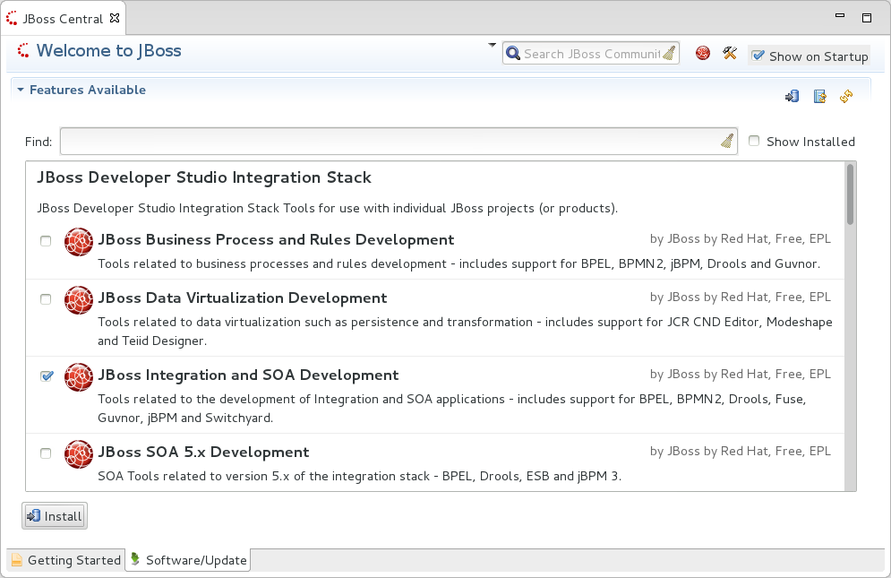
Figure 3.1. Find JBoss Developer Studio Integration Stack in JBoss Central Software/Update Tab
- In the Install wizard, ensure the check boxes are selected for the software you want to install and click . It is recommended that you install all of the selected components.
- Review the details of the items listed for install and click . After reading and agreeing to the license(s), click I accept the terms of the license agreement(s) and click . The Installing Software window opens and reports the progress of the installation.
- During the installation process you may receive warnings about installing unsigned content. If this is the case, check the details of the content and if satisfied click to continue with the installation.
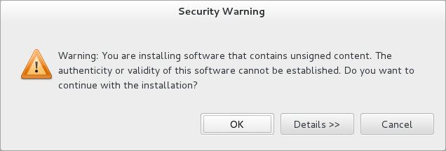
Figure 3.2. Warning Prompt for Installing Unsigned Content
- Once installing is complete, you are prompted to restart the IDE. Click to restart now and if you need to save any unsaved changes to open projects. Note that changes do not take effect until the IDE is restarted.
Important
3.3. Helpful Tips
- Honor all XML schema locations
- After installation, go to → → → and ensure
Honor all XML schema locationscheck box is cleared. This prevents erroneous XML validation errors from appearing onswitchyard.xmlfiles. - DTD warning
- Importing SwitchYard quickstarts into JBoss Developer Studio results in non-fatal warnings regarding
log4j.dtd. These can be safely ignored. To stop receiving the warning, ensure the filelog4j.xmlis closed before starting a project. - JavaSE-1.6 error message
- When commencing a project, a warning may be displayed saying "Build path specifies execution environment JavaSE-1.6". To disable this warning, go to your Java preferences and ensure that JavaSE-1.7 JDK is checked to support JavaSE-1.6 environments.
3.4. Running Quickstarts from JBoss Developer Studio
This topic demonstrates how to import a quickstart application to JBoss Developer Studio and then deploy it to a running application server.
The JBoss Integration and SOA Development tools must be installed from the JBoss Developer Studio Integration Stack.
- Open JBoss Developer Studio.
- Click → → → .
- Select and navigate to the quickstart directory, for example,
EAP_HOME/quickstarts/switchyard/bean-serviceand then select .The import tool scans the directory to locate the associatedpom.xmlfile. - Click .
- The quickstart is listed in the Project Explorer view. You can expand the project to explore its contents.
- In the Project Explorer view, right-click on the project's name and click → → .
The quickstart application is deployed to the server and enabled by default.
3.5. Import Projects From a Git Repository in JBoss Developer Studio
- Start the Red Hat JBoss server (if not already running) by selecting the server from the server tab and click the start icon.
- Select → and navigate to the Git folder. Open the Git folder to select and click next.
- Select the repository source as and click next.
- Enter the details of the Git repository in the next window and click next.
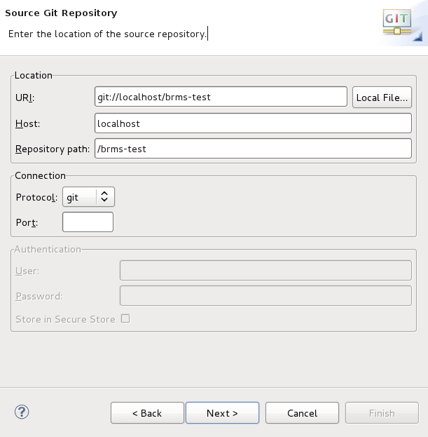
Figure 3.3. Git Repository Details
- Select which branch you want to import in the next window and click next.
- You are presented with the option to define the local storage for this project. Enter (or select) a non-empty directory, make any configuration changes and click next.
- Import the project as a general project in the next window and click next. Name this project and click Finish.
3.6. Setting a New Rules Runtime in JBoss Developer Studio
- Download and unzip the runtime jars files located in the
jboss-brms-engine.ziparchive of the JBoss BRMS Deployable zip archive (available from Red Hat Customer Portal). - From the Red Hat JBoss Developer Studio menu, select Window and click Preferences.
- Select → → .
- Click Add; provide a name for the new runtime, and click Browse to navigate to the directory where the runtime is located.
- Click OK, select the new runtime and click OK again. A dialog box indicates, if you have existing projects, that JBoss Developer Studio must be restarted to update the Runtime.
Chapter 4. Setting Up the Server
4.1. Add JBoss EAP Server
- In JBoss Developer Studio, click the view. If the view is not visible, click → → .
- If no servers have been previously created then the Servers view displays a new server hyperlink. Click this link to create a new server.If there are one or more existing servers, right-click an existing server and click → .
- In the Define a New Server dialog, select a JBoss Enterprise Application Platform server from the Select the server type list.
- The Server's host name and Server name fields are completed by default. In the Server name field, you can type a custom name by which to identify the server in the Servers view.
- From the Server runtime environment list, select an existing server runtime environment for the application server type. Alternatively, to create a new runtime environment click and complete the fields and options as appropriate.
Note
If the Server runtime environment field is not shown, no server runtime environments exist for the selected application server type. To create a new server runtime environment without canceling the wizard, click and complete the fields and options as appropriate. - Click .
- The server behavior options displayed vary depending on the selected application server type. To specify that the server life-cycle is to be managed from outside the IDE, select the Server is externally managed check box.To specify that the server should be launched to respond to requests on all hostnames, select the Listen on all interfaces to allow remote web connections check box.From the location list, select Local. Click Next.
Note
The Expose your management port as the server's hostname option, which enables management commands sent by the IDE to be successfully received by the server, is bypassed for local servers regardless of whether the check box is selected. - To select applications to deploy with this server, from the Available list select the applications and click Add. Applications to be deployed are detailed in the Configured list.
- Click to create the server.
The new server appears in the list of servers in the Servers panel.
Important
Chapter 5. Rules
5.1. DSL
5.2. DSL Editor
- In JBoss Rules, the DSL configuration is stored in
.dslfiles. These can be created selecting → → → → from the projects context menu.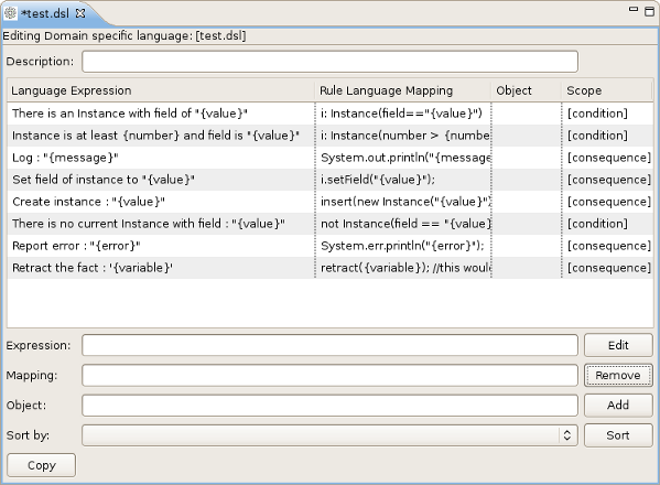
Figure 5.1. The DSL editor
5.3. DSL Editor Components
Table 5.1. DSL Editor Components
| Components | Description |
|---|---|
| Description | User's comments on a certain language message mapping. |
| Table of language message mappings | The table is divided into 4 rows:
|
| Expression | Shows the language expression of the selected table line (language message mapping). |
| Mapping | Shows the rule of language mapping for the selected table line (language message mapping). |
| Object | Shows the object for the selected table line (language message mapping). |
| Sort By | This option allows you to change the sorting order of the language message mappings. To do this select from the drop down list the method of sorting you want and click the button. |
| Buttons |
|
5.4. Add a Language Mapping Wizard
Procedure 5.1. Task
- Click the button and a dialog box appears.
- Enter the details of your language mapping wizard into the relevant fields.
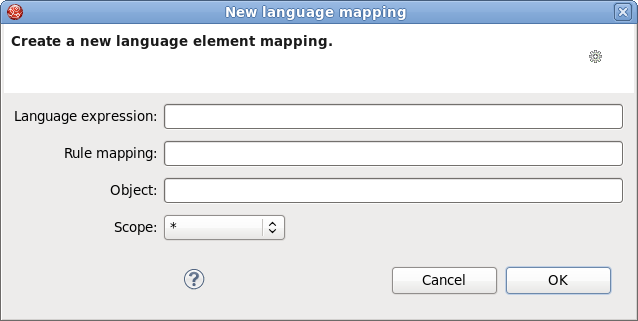
Figure 5.2. Dialog box
5.5. Edit the Language Mapping Wizard
- This wizard can be opened by double-clicking a line in the table of language message mappings or by clicking the button.
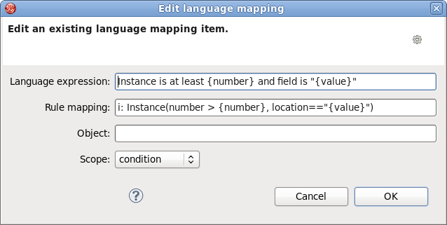
Figure 5.3. Editing options
- To change the mapping, edit the appropriate options and click the button.
5.6. JBoss Rules Flow Editor
- Ruleflows can only be set by using the graphical flow editor which is part of the JBoss Rules plug-in for JBoss Developer Studio. Once you have set up a JBoss Rules project, you can start adding ruleflows. Add a ruleflow file (.rf) by clicking on the project and selecting → → → .By default these ruleflow files (.rf) are opened in the graphical Flow editor.
- The Flow editor consists of a palette, a canvas and an outline view. Select the element you would like to create in the palette and then add it to the canvas by clicking on the preferred location.
- Clicking on the Select option in the palette and then on the element in your ruleflow allows you to view and set the properties of that element in the Properties view.
- The Outline view is useful for complex schemata where not all nodes are seen at one time. Using the Outline view allows you to easily navigate between parts of a schema.
5.7. Different Types of Control Elements in Flow Palette
Table 5.2. Different Types of Control Elements in Flow Palette
| Icon | Name | Description |
|---|---|---|
 | Select | Select a node on the canvas. |
 | Marquee | Selects a group of elements. |
 | Sequence flow | Joins two elements on the canvas |
5.8. Different Types of Nodes in Flow Palette
Table 5.3. Different Types of Nodes in Flow Palette
| Icon | Name | Description |
|---|---|---|
 | Start Event | The start of the ruleflow. There can only have one start node. The Start Event cannot have incoming connections and should have one outgoing connection. Whenever the ruleflow process is started, the execution is started here and is automatically forwarded to the first node linked to this Start Event. |
 | End Event | A ruleflow file can have multiple End Events. This node should have one incoming connection and no outgoing connections. When an end node is reached in the ruleflow, the ruleflow is terminated (including other remaining active nodes when parallelism is used). |
 | Rule Task | Represents a set of rules. A Rule Task node should have one incoming connection and one outgoing connection. The RuleFlowGroup property is used to specify the name of the ruleflow-group representing the set of rules. When a Rule Task node is reached in the ruleflow, the engine starts executing rules that are part of the corresponding ruleflow-group. Execution automatically continues to the next node when there are no more active rules in this ruleflow-group. |
 | Gateway[diverge] | Allows you to create branches in your ruleflow. A Gateway[diverge] node should have one incoming connection and two or more outgoing connections. |
| | Gateway[converge] | Allows you to synchronize multiple branches. A Gateway[converge] node should have two or more incoming connections and one outgoing connection. |
 | Reusable Sub-Process | Represents the invocation of another ruleflow from this ruleflow. A subflow node should have one incoming connection and one outgoing connection. It contains the property processId which specifies the ID of the process that should be executed. When a Reusable Sub-Process node is reached in the ruleflow, the engine starts the process with the given ID. The subflow node continues only if the other subflow process has terminated its execution. The subflow process is started as an independent process, which means that the subflow process is not terminated if this process reaches an end node. |
 | Script Task | Represents an action that should be executed in this ruleflow. A Script Task node should have one incoming connection and one outgoing connection. It contains the property "action" which specifies the action that should be executed. When a Script Task node is reached in the ruleflow, it executes the action and continue with the next node. An action should be specified as a piece of (valid) MVEL code. |
5.9. Rule Editor
.drl (or .rule in the case of spreading rules across multiple rule files) extension. The editor follows the pattern of a normal text editor in JBoss Developer Studio, with all the normal features of a text editor.
5.10. Content Assist
Ctrl+Space. Content Assist shows all possible keywords for the current cursor position. It also suggests all available fields in a message.
5.11. Code Folding
5.12. Synchronization with Outline View
5.13. Rete Tree View
.drl file. Just click on the Rete Tree tab at the bottom of the Rule editor. Afterwards you can generate the current Rete Network visualization. You can push and pull the nodes to arrange your optimal network overview.
Note
5.14. Breakpoints
5.15. Creating Breakpoints
- To create breakpoints in the Package Explorer view or Navigator view of the JBoss Rules perspective, double-click the selected
.drlfile to open it in the editor. - You can add and remove rule breakpoints in the
.drlfiles in two ways:- Double-click the rule in the Rule editor at the line where you want to add a breakpoint. A breakpoint can be removed by double-clicking the rule once more.
Note
Rule breakpoints can only be created in the consequence of a rule. Double-clicking on a line where no breakpoint is allowed does nothing. - Right-click the ruler. Select the action in the context menu. Choosing this action adds a breakpoint at the selected line or remove it if there is one already.
- The Debug perspective contains a Breakpoints view which can be used to see all defined breakpoints, get their properties, enable/disable and remove them. You can switch to it by clicking → → → .
5.16. Debugging
- JBoss Rules breakpoints are only enabled if you debug your application as a JBoss Rules Application. To do this you should perform one of two actions:
- Select the main class of your application. Right-click on it and select → .
- Alternatively, select → to open a new dialog window for creating, managing and running debug configurations.Select the JBoss Rules Application item in the left tree and click the button (leftmost icon in the toolbar above the tree). This creates a new configuration with a number of the properties already filled in based on main class you selected in the beginning. All properties shown here are the same as any standard Java program.
Note
Remember to change the name of your debug configuration to something meaningful. - Click the button on the bottom to start debugging your application.
- After enabling the debugging, the application starts executing and halts if any breakpoint is encountered. This can be a JBoss Rules rule breakpoint, or any other standard Java breakpoint. Whenever a JBoss Rules rule breakpoint is encountered, the corresponding
.drlfile is opened and the active line is highlighted. The Variables view also contains all rule parameters and their value. You can then use the default Java debug actions to decide what to do next (resume, terminate, step over, etc). The debug views can also be used to determine the contents of the working memory and agenda at that time as well (the current executing working memory is automatically shown).
Chapter 6. JBoss Developer Studio BPEL Projects
6.1. BPEL
6.2. Apache ODE
6.3. Logging into BPEL
Procedure 6.1. Task
- Access the BPEL console at the following URL: http://localhost:8080/bpel-console. A login screen appears.
- Enter your credentials. The default username is
adminwith passwordadmin. - To change your login details, access the
Settingstab in the BPEL editor and click onUsers. In this section there are fields to change your username and password.
6.4. Creating a BPEL Project
- First, select → → → → or from the menu bar. Then click the button.
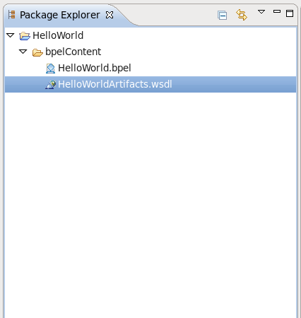
Figure 6.1. Diagram 1
- Enter a project name in the Project Name field.
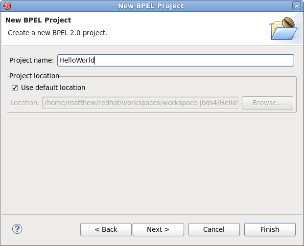
Figure 6.2. Diagram 2
- Click the button. The following screen appears.

Figure 6.3. Diagram 3
- You have now created a new project.
6.5. Creating a BPEL Process
- First, select → → → → and click .
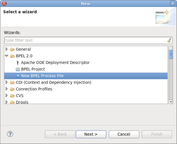
Figure 6.4. Diagram 1
- From here you can choose to create a BPEL process from a template or a service description. The former is recommended.
- Enter the following information:
Table 6.1. Fields and Values
Field Value BPEL Process NameEnter a process name. For example, HelloWorld.NamespaceEnter or select a namespace for the BPEL process.TemplateSelect the appropriate template for the BPEL process. When you select the template, you can see information about it. Select Synchronous BPEL Process.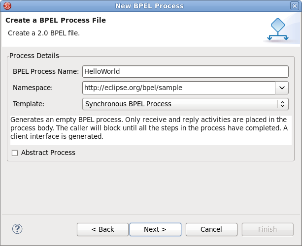
Figure 6.5. Diagram 2
- Click . On this page, you can customize your WSDL service details using a template. Enter the following information:
Table 6.2. Fields and Values
Field Value Service NameA WSDL service name for the BPEL process. The default name is HelloWorld.Port NameA WSDL port name for the BPEL process. The default name is HelloWorldPort.Service AddressAn address of the WSDL service for the BPEL process. The default value is http://localhost:8080/HelloWorld.Binding ProtocolThe binding protocol that you use in the WSDL. You can choose SOAP or HTTP. The default value is SOAP.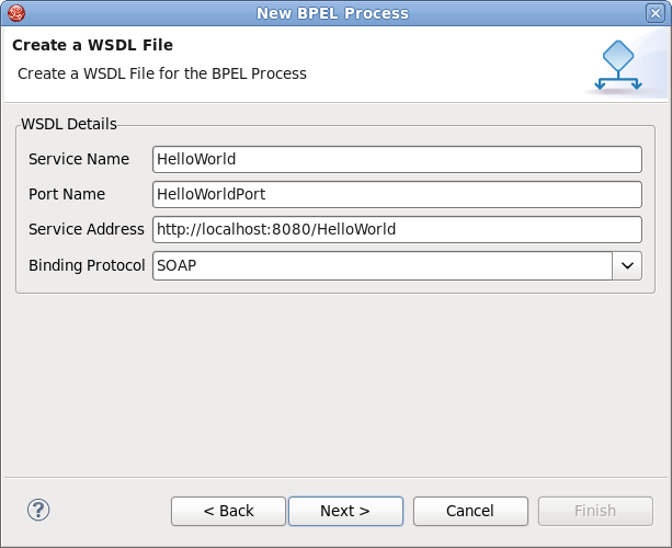
Figure 6.6. Diagram 3
- Click the button. On the this page, you can select a folder for the process file from the projects in your workspace. If a folder is not selected, the default folder
HelloWorld/bpelContentis used. - Click the button. The process is complete.
Note
All of the files used in your BPEL project must be under thebpelContentfolder of a BPEL project.
6.6. Create a New Server Runtime
Procedure 6.2. Task
- Go to the New Server wizard.
- Click on Add.
- Fill in the name if you wish to do so (this step is optional because the name is preset.
- Click on Browse and select the home directory.
- Select one of the available configurations (the configuration you choose must have the BPEL engine available).
- Click on Finish.
6.7. Editing a BPEL Process File
- Open the Properties view and Palette view by right-clicking the BPEL editor and selecting the Show in Properties or Show Palette in Palette view options.
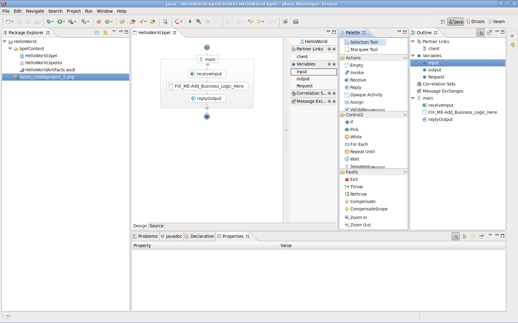
Figure 6.7. Diagram 1
- In the Palette view, drag and drop your chosen BPEL element into the BPEL editor.
- Switch to the Properties view to see information on the BPEL process.
- The contents of the Properties view is automatically updated as elements are selected in the BPEL editor.
6.8. Tabs Shown in the Properties View
Table 6.3. Tabs Shown in the Properties View
| Tab | Description |
|---|---|
| Description | Displays information about the element such as name, size, etc. |
| Details | Shows detailed and important information about the element. Most of the properties of an element are set in this section. |
| Join Behavior | Shows the Join Failure property of the element. |
| Documentation | Shows the documentation sub-element of an element. |
| Imports | Allows you to choose which documents are imported into the BPEL process definition. |
| Namespaces | Lets you edit the defined namespaces in the BPEL process document. |
6.9. Observing a BPEL Process
- Change the Empty element between elements receiveInput and replyOutput to Assign.
- Add an Assign element between the receiveInput element and replyOutput element.
- Click the Assign element in the BPEL editor to see the properties information in the Properties view.
- Set its name in the Description tab as assignHelloMesg.
- In the Details section of Properties view, click the New button to add a copy sub-element to the element. Assign "Variable to Variable" (input:string to result:string). An " initializer" popup dialog box appears. Click the Yes button.
- Navigate down to the desired component and click it. The icon to the left of the component name indicates its type: a blue dot is the BPEL variable, an envelope is a message, an "e" is an XML element. Click the button once more and select Expression to Variable (assign
concat($input.payload/tns:input, ' World')) to result:string.
6.10. Adding a Service to a WSDL File
HelloWorldArtifacts.wsdl file is added to a service when you create a BPEL process file. A default service is already defined in this WSDL file, however you may wish to add your own service. This task shows you how to do this so that you are able to add the service that is most appropriate to your situation.
- Open the file
HelloWorldArtifacts.wsdlin the HelloWorld project. - Right-click the WSDL editor and select the Add Service option. A new service should appear in the editor. Name it HelloWorldProcessService. It has the Port named NewPort. Select it, right-click on it and rename it to HelloWorldProcessPort in the Properties view.
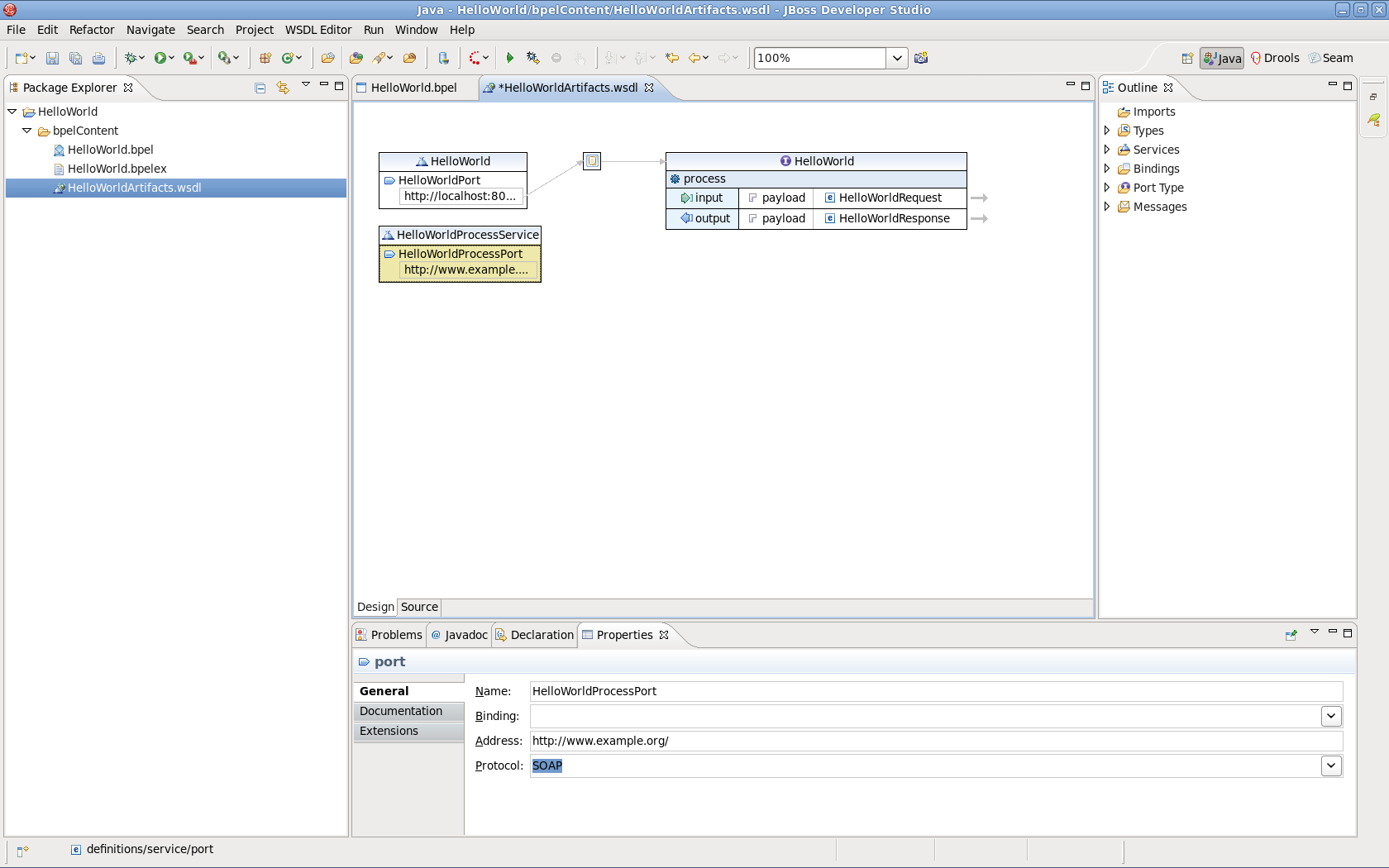
Figure 6.8. Diagram 1
- Right-click in the whitespace of the WSDL editor and select the Add Binding option. A new Binding component appears in the editor. Name it HelloWorldSOAPBinding. Select it, and in the General tab of the Properties view and select HelloWorld as a port type in the PortType field.
- Click on the button to open the Binding Wizard.
- In the wizard, select SOAP as the Protocol. Click the button to close the wizard.
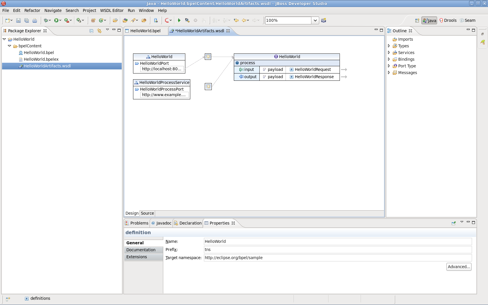
Figure 6.9. Diagram 2
- Click the HelloWorldProcessPort property in the General section of the Properties view.
- Select HelloWorldSOAPBinding in the Binding combobox.
- Enter http://localhost:8080/bpel/processes/HelloWorld?wsdl in the Address field.
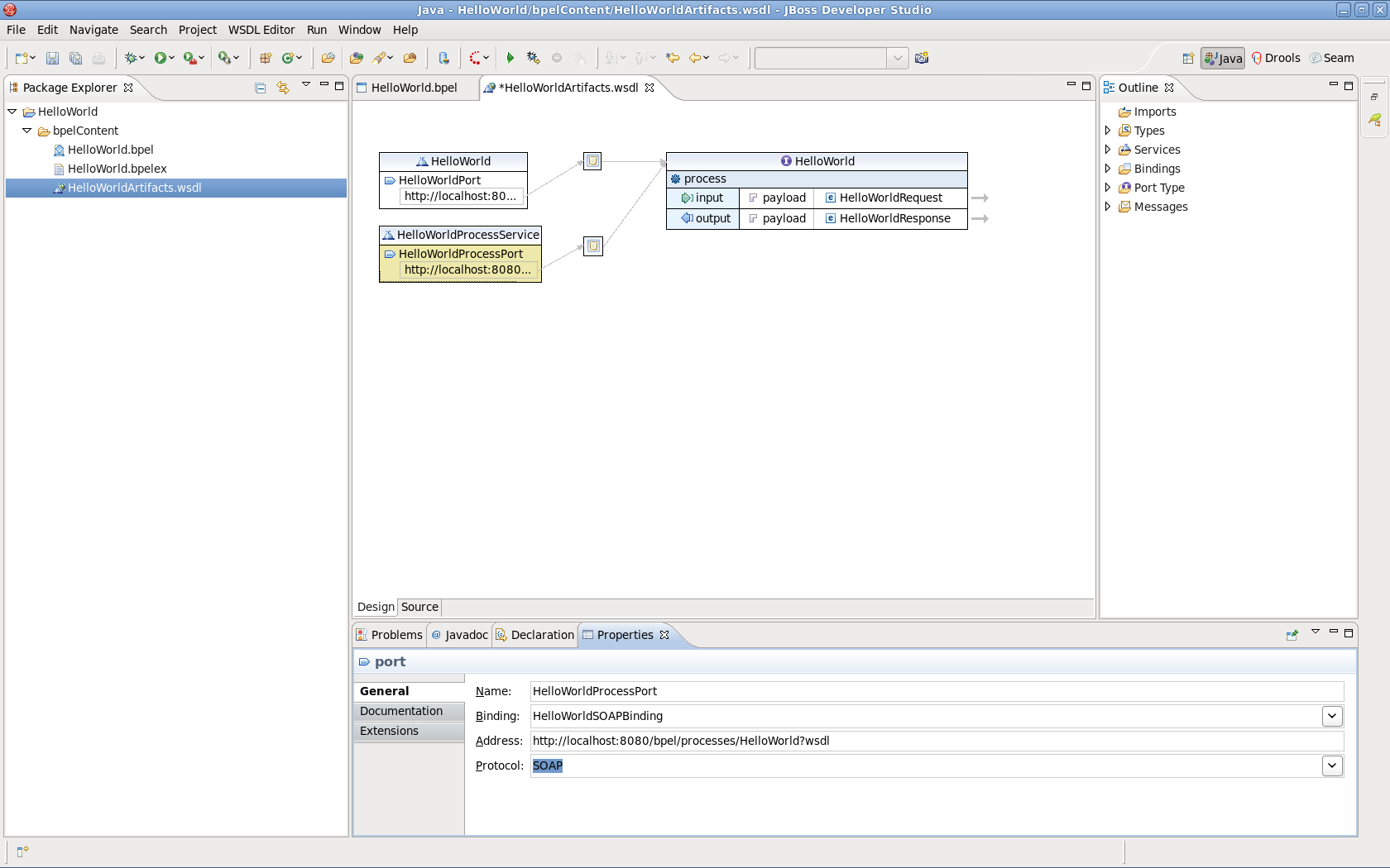
Figure 6.10. Diagram 3
6.11. Creating a deploy.xml File
- To create a new
deploy.xmlfile for deploying BPEL projects, select → → → → . Click the button.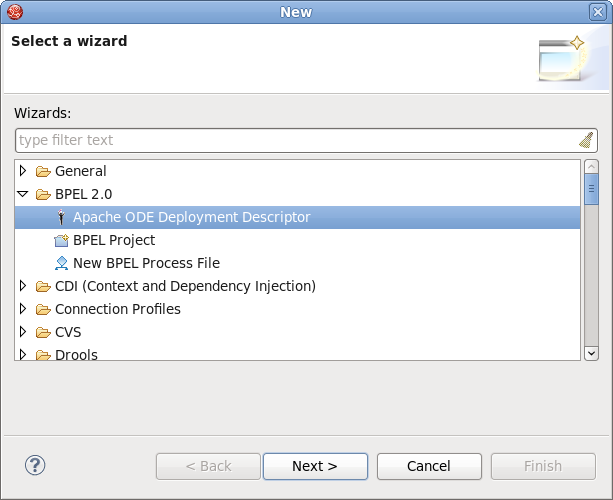
Figure 6.11. Diagram 1
- On this page of the wizard, enter the BPEL Project. Do so by clicking the button to select the BPEL project in your workspace that you want to deploy to the runtime.
- Select the
bpelContentfolder in your new BPEL project for the BPEL Project field. Do not change the default file name which isdeploy.xml. - Click on the button to close the wizard and a new
deploy.xmlfile is created.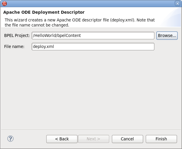
Figure 6.12. Diagram 2
- Finally, double-click the
deploy.xmlfile to open it in ODE Descriptor Deployment Editor. In the Inbound Interfaces section, click the Associated Port column and select HelloWorldProcessPort in the combobox.The Related Service and Binding Used columns should be automatically filled in. Save the changes to thedeploy.xmlfile.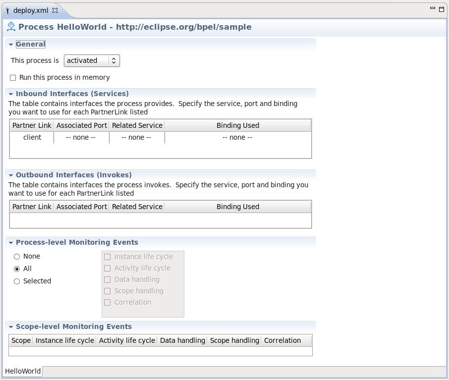
Figure 6.13. Diagram 3
6.12. Creating JBoss BPEL Server
- Open the Servers view by selecting → → → → .
- Right-click the Servers view and select → to open the New Server wizard.
- Select JBoss EAP 6 as a server type.
- Click the button. On this page, input your JBoss EAP location. Then click .
- Select HelloWorld, then click the button to add the project to the server. Finally, click the button.
- Start the server by right-clicking on the server and selecting the Start item.
- Enter the link http://localhost:8080/bpel-console/app.html in your web browser to access the deployed processes.
6.13. Creating Correlation Sets
- To create a correlation for a messaging activity, go to the dashboard tab and click the plus button. Set a name for the set when prompted.
- In view, click the tab and then click the button. The dialog box appears.
- Enter a name for the new WSDL property and its type. (Either an XSD simple type or an XML Schema element.)
- Click the button to select a type. The Type Selection dialog box appears.
- Click New in the Aliases section to create a new WSDL property alias.
- Select either the Message Type, XSD Simple Type or XML scheme Element radio button and click to select its type. Click .
- A correlation can be assigned to a messaging activity (for example, Invoke, Receive, Reply). Select the activity, click Add on the Correlation property tab and choose the appropriate correlation set.
6.14. Example BPEL Component Implementation
<sca:component name="SayHelloService">
    <bpel:implementation.bpel process="sh:SayHello" />
    <sca:service name="SayHelloService">
        <sca:interface.wsdl interface="SayHelloArtifacts.wsdl#wsdl.porttype(SayHello)"/>
    </sca:service>
</sca:component>
Warning
6.15. Structure of a SwitchYard BPEL Application
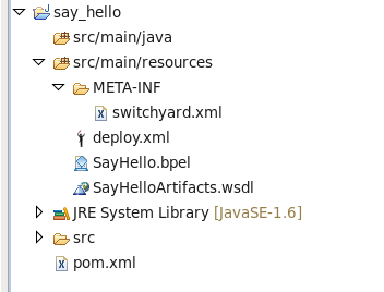
Figure 6.14. BPEL application structure
- As shown, the artifacts are structured within the src/main/resources folder.
- The
switchyard.xmlconfiguration file is located in the META-INF folder. - The BPEL deployment descriptor (
deploy.xml) and the BPEL process definition are located in the root folder. - The WSDL interface definitions (and any accompanying XSD schemas) are located in sub-folders. The BPEL process and SwitchYard BPEL component configuration must define the correct relative path.
6.16. Wizards
Table 6.4. Wizards
| Wizard name | Description |
|---|---|
| New BPEL Project wizard | Creates a faceted project which can be deployed to the JBoss Riftsaw runtime engine. It is available by selecting → → → → . The bpelContent folder contains all the files necessary for your project. |
| New BPEL Process File Wizard | Creates a BPEL process based on one of several templates defined by the wizard. The wizard assumes the new BPEL process is to be created in the current project of the Project Explorer or Navigator view. If a BPEL process of the same name already exists within the project, a warning message is displayed before any action is performed. |
| New BPEL Deployment Descriptor | Use this wizard to create a Deployment Descriptor file. This file is a manifest for the web service and is required if the BPEL process is to be deployed to a runtime engine. The BPEL Deployment Descriptor Editor opens once this wizard is completed. |
Important
bpelContent folder hierarchy if you intend to deploy the process. Complex projects may be organized into a folder hierarchy, but these folders must be contained within bpelContent.
Deployment Descriptor file must be contained within the bpelContent folder and at the root of any folder hierarchy.
6.17. Views
Table 6.5. Views
| View | Description |
|---|---|
| Outline | The Outline view provides a structural layout of the BPEL process. You can view the process as either a hierarchical tree-structured outline or as a thumbnail view by pressing the associated button. |
| Palette |
The primary editing, creation and viewing tools of the BPEL Designer are accessed from the Palette. The Palette can be docked either at the right or left edge of the BPEL Designer main window, or it can be detached and displayed in its own view.
|
| Dashboard | This panel is embedded in the BPEL Designer canvas and provides a quick overview of the BPEL elements that are defined for the currently selected activity or BPEL process. The process name appears at the top of the Dashboard. The main Dashboard area lists all of the Partner Links, Variables,Correlation Sets and Message Exchanges currently defined for the process. The green plus symbol and grey x symbol allow you to add and delete each of these elements. In-line editing of all element names works by selecting the name and then clicking again to enable the editor. |
6.18. Property Section Tabs
Table 6.6. Property Sections
| Name | Description |
|---|---|
| Description tab | The Description tab contains the activity name. Names must follow XML element naming conventions, limiting characters to letters, numbers and certain special characters only (spaces are not permitted). |
| Join Behavior tab | Join conditions are evaluated by the target activities of links. With the drop-down Expression language menu, enter an XPath expression that defines the condition of the join. The Suppress Join Failure behavior defined by the process or a containing scope can be overridden with the radio buttons at the bottom. |
| Correlation tab | The Correlation tab lists all correlations that are used by the currently selected Receive, Reply or Invoke activity. Correlations can be added to or removed from the activity through this tab. |
| Namespaces tab | Namespaces are URIs (Uniform Resource Identifiers) that uniquely identify a set of resources on the Internet. Shorthand aliases called prefixes are typically used in XML files to make them more readable. The Namespaces tab lists all of the namespace URIs and their prefixes in scope for the currently selected activity. Whenever you create a reference to an external property (an element defined in an XSD) whose namespace has not yet been assigned a prefix, the BPEL Designer prompts you to create a prefix. This can also be done through the Namespace tab of the Properties sheet for the property by clicking the button. |
| Message Exchange tab | Message exchanges are used to associate a Reply activity with an inbound message activity and can be either a Receive , OnMessage or OnEvent . These are descriptive names given to a request-response conversation between two parties and must conform to XML element naming conventions. |
6.19. Process Property Sheet Tabs
Table 6.7. Process Property Sheet Tabs
| Name | Description |
|---|---|
| Description tab | The Description tab allows you to change the process name and its namespace URI. |
| Details tab | The Process Details tab allows you to select the default Expression and Query language. If you set Exit on Standard Fault to Yes, it causes the process to terminate if a WS-BPEL standard fault, other than a join failure, is encountered. Currently only XPath 1.0 is supported. |
| Join Behavior tab | The Process Join Behavior tab determines how the process handles the join failures. When set to Yes, any JoinFailure fault is ignored for all activities in the process. An activity is able override this value or inherit the value from its parent. |
| Imports tab | The Imports Detail tab lists all of the imported service interfaces (WSDL) and XML Schemas (XSD) used by the process. Additional WSDL and XSD files can be added to the imports on this page. After a new resource has been imported, you may assign a prefix to the namespace URI from the Namespaces tab. Imported resources must be located in the project root folder (bpelContent by default) or in a sub-folder. |
| Namespace tab | Here you can enter a name for your project. |
| Documentation tab | Click this tab to view relevant documentation pertaining to your process. |
6.20. Details Tab Options
Table 6.8. Details Tab Options
| Name | Description |
|---|---|
| Partner Links | Partner Links help define the conversations between two services. They define the roles each partner plays in the conversation and the types of messages that can be exchanged between them. The Details tab allows you to choose the Expression language and Query language for selecting elements of a Partner Link . |
| Variables | Variables are used in BPEL to store inbound and outbound messages for examination and manipulation by the business logic. They can also be used to save intermediate results and the process state. The three kinds of variable declarations are messages types, XML Schema types and XML Schema elements. The Details tab allows you to define the variable declared type and its structure by selecting from known types. Once a variable type has been defined, the structure of the variable is shown. Clicking on the hyperlink opens the WSDL or XML Schema editor for the selected type or element. |
| Empty | The Empty activity is a placeholder for any undefined Basic Activity and is intended to eventually be replaced by a real activity before the process can actually be executed. If the BPEL engine encounters an Empty activity, it is ignored. The Details tab allows you to select one of four basic actions: Invoke , Receive , Reply and Assign . Hovering the mouse over one of the selection buttons displays a brief description of that activity. |
| Invoke | The Invoke activity requires a Partner Link name and an Operation as defined in the WSDL for that service. You can use the Quick Pick tree control on the right to select the Partner Link and Operation . For one-way invocations, specify only an Input Variable . For request-response invocations you must also specify an Output Variable . The check box labeled Use WSDL Message Parts Mapping provides an alternative to using variables for the request message. |
| Receive | A Receive activity requires a Partner Link name and an Operation as defined in the WSDL for this service. You can use the Quick Pick tree control on the right to select the Partner Link and Operation . A previously defined variable can be used to hold the message data, or the Use WSDL Message Parts Mapping check box can be set to store the incoming message in an anonymous WSDL message variable. The Create a new Process Instance check box, when enabled, causes the BPEL engine to start a new process. This starts a new conversation with a client. |
| Reply | A Reply activity requires a Partner Link name and an Operation as defined in the WSDL. You can use the Quick Pick tree control at the right to select the Partner Link and Operation . A previously defined variable can be used to provide the response message data, or the Use WSDL Message Parts Mapping check box can be set to use the data from the anonymous WSDL message variable. |
| Opaque | Opaque activities are only used in abstract processes and are meant as placeholders for other activities yet to be determined. When you drag and drop an Opaque activity onto the drawing canvas, the process is converted to a non-executable, abstract process. |
| Assign | The Assign section contains an array of variables including message options and management buttons. Additional type selection or data entry widgets appear below the From and To combo boxes, depending on the source and target item categories selected in the combo boxes. Initially these are controls for the selection of process variables, since the default combo box selection is Variable . |
| Validate | The Validate details tab contains a list of variables to be validated. |
| While and RepeatUntil | These activities have the same details tab, which allows you to specify an XPath expression to be evaluated for the conditional activity. |
| Link | The Link detail tab allows you to specify a condition that causes Flow synchronization to be satisfied and allow the target activity to continue. This is similar to the details tab of the other conditional activities. |
| Pick | The Pick tab allows you to specify whether the event creates a new process instance. |
| OnMessage | The OnMessage activity is used in Pick and event handlers. The Details tab allows you to specify the Partner Link , Operation and Message Type expected by the activity, and the process variable that contains the received message data. |
| OnAlarm | The OnAlarm activity is used in either a Pick or event handler to handle timeouts while waiting for messages to arrive. This activity can be configured to wait for a certain period of time or until a specific date and time. The Details tab allows you to specify the Partner Link , Operation and Message Type expected by the activity, and the process variable that contains the received message data. Repeat conditions are only allowed for an OnAlarm in an event handler. This allows the activities enclosed in the activity to be executed repeatedly. Repeat duration is the amount of time the process waits before each repetition. |
| ForEach | ForEach allows you to specify a counter variable to be used for keeping track of the loop iterations. The Parallel execution check box executes all iterations in parallel. The Counter Values tab is where the starting and ending counter values are specified. The optional Completion tab allows you to specify the early termination condition for the loop. |
| Wait | The details tab of the Wait activity allows you set a delay ( Duration ) or specify a date and time to continue process execution. |
| Scope | The details tab for the Scope activity allows you to define whether the Scope is isolated. |
| Throw | The Throw activity invokes a fault handler in an enclosing Scope activity. Throw requires the name of either a standard BPEL fault, or the name of a user-defined fault message. A variable is used to hold the value of the fault data. |
| CompensateScope | The CompensateScope activity invokes a compensation handler in the Scope or the Invoke activity given by the name of the Target Activity. |
6.21. BPEL Designer Features
Table 6.9. BPEL Designer Features
| Name | Description |
|---|---|
| Drawing Canvas | Contains the graphical representation of the BPEL process and is displayed when the Design tab at the bottom of the editor window is selected. Clicking on any of the activity names activates an in-line editor, allowing you to edit the process name. To finish editing, press the ENTER key or change focus by clicking on a different window control. |
| Source | This tab displays the XML (text) representation of the process. Any changes made in one view are shown in the other. The default layout of activities is top-to-bottom, but can be changed to horizontal layout from the context menu. |
| Palette | The primary editing, creation and viewing tools of the BPEL Designer are accessed from this tool. |
| Dashboard | Provides an overview of the BPEL process. |
| Property Sheet | Displays the properties of an activity when it is selected in the drawing canvas. |
| Outline | This panel provides a structural view of the BPEL process. |
6.22. BPEL Designer Concepts
Table 6.10. BPEL Designer Concepts
| Name | Description |
|---|---|
| Assign error | Hovering your mouse over this icon displays an error message. |
| Basic activities | Basic activities are represented on the drawing canvas as rounded rectangles containing an icon and the user-defined name of the activity. The Actions section of the Palette contains all of the basic activities. For example: Assign , Invoke and Receive . |
| Start and End | Every process has Start and End activities that act as placeholders for visualizing the beginning and end of the process flow. |
| Assign activity | The Assign activity allows you to manipulate variables and message contents that are defined in the process. |
| Invoke | The Invoke activity is used to send a message to an external service (one-way invocation) and, optionally, wait for a response (request and response). An Invoke can also define a compensation handler and a fault handler to handle exception conditions. |
| Receive | The Receive activity waits for a specific message type from a service client. |
| Reply | The Reply activity is used to respond to clients with a specific message type or a fault message. |
| Validate | The Validate activity is used to validate the values of variables against their XML Schema and WSDL data definitions. This includes the variable’s data type as well as structure. If validation fails, the BPEL standard fault invalidVariables is thrown. Validation is typically performed just before sending messages to a partner or client, or after receiving a message to ensure the message contains all required data. |
| Wait | The Wait activity delays process execution for a certain amount of time, or until a given date and time. This is typically used to invoke an operation at a certain time. For example to update process state hourly or daily, or to collect some information from another service at a certain time. |
6.23. BPEL Deployment Descriptor Editor Properties
Table 6.11. BPEL Deployment Descriptor Editor Properties
| Name | Description |
|---|---|
| Process selection tabs | Click on these tabs to display the configuration page for each process. |
| Initial process state | The process can be deployed in either an active , inactive or retired state. |
| Inbound interfaces selection | Select the WSDL port type that clients use to invoke this service. |
| Output interfaces selection: | Each invoked service (if any) requires you to select its port type. |
| Scope-level monitoring events | The BPEL engine can be configured to generate monitoring events for each Scope defined in the process. |
Note
6.24. Dialogs
Table 6.12. Dialogs
| Name | Description |
|---|---|
| XPath expression editor (embedded control) | The XPath expression editor provides context-sensitive assistance in the form of pop-up proposals. The light bulb icon indicates that content assist is available by pressing the CTRL and SPACE keys simultaneously. The BPEL 2.0 specification provides for the definition of an XPath language version at the process level, as well as the activity level (for those activities that make use of XPath). However, only XPath 1.0 is supported by the BPEL Designer and the JBoss Riftsaw runtime engine. |
| Quick pick (embedded control) | Tree control is used in many property pages for selecting message parts, partner links and operations. |
| Type selection |
This dialog is displayed whenever the BPEL Designer requires you to select a message, message part, XML Schema type or XML element.
|
6.25. Cheat Sheets
Procedure 6.3. Task
- Access the cheat sheet by clicking → .
- The cheat sheet opens in a separate view as show below. Click on the link to begin.
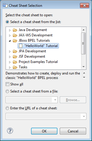
Figure 6.15. Diagram 1
- You can now view tutorials for plug-in tools.
6.26. Context Menu
Chapter 7. JBoss Developer Studio Guvnor Tasks
7.1. Guvnor Repository Exploring Perspective
- In the JBoss Developer Studio workbench menu, select → → to view the perspective list.
- Choose the perspective you wish to use. JBoss Developer Studio standard views such as Properties and Resource Navigator are useful.
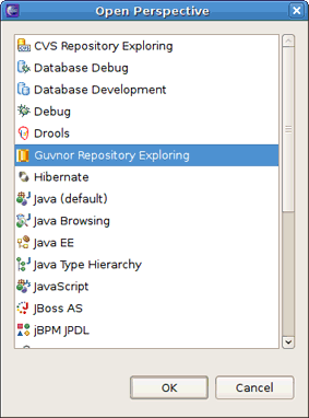
Figure 7.1. Perspective list
7.2. Creating a New Guvnor Connection
- Open a new connection.
- Start the Guvnor Connection wizard in one of the following ways:
- Select → → → → within JBoss Developer Studio.
- Go to the Guvnor Repositories view using the drop-down menu.
- Use the menu button to select a new connection. This is added to JBoss Developer Studio automatically.
7.3. Configuring the Guvnor Connection Wizard
- Default values appear in the Location, Port and Repository fields. You can edit these fields using their corresponding text boxes.
- To input a Guvnor repository URL into the respective fields, drag and drop it into the Location field.
Important
When using JBoss Developer Studio tooling, you cannot access Guvnor data if this Guvnor is deployed on a secured HTTP (HTTPS). - The EGT calls the Guvnor repository at various times, such as when it is determining if any resource updates are available. If you use session authentication, the authentication dialog appears at different times during the JBoss Developer Studio workbench session, depending on what actions you take. We recommend saving the authentication information in the JBoss Developer Studio keyring.Click on save username and password to save your details into the JBoss Developer Studio workbench's keyring file.
Note
If the authentication information is not stored in the keyring, then the EGT uses a session authentication. This means that the credentials supplied are only used during the lifetime of the JBoss Developer Studio workbench instance.Note
If an authentication failure error occurs, you can retry the same operation and supply different authentication information.Note
The JBoss Developer Studio keyring file is distinct from keyring files found in some platforms such as Mac OS X and many forms of Linux. Thus, sometimes if you access a Guvnor repository outside the EGT, the keyring files might become outdated, and you are unexpectedly prompted for your credentials in JBoss Developer Studio. Enter your username and password to continue.
7.4. Getting Local Copies of Guvnor Files
- To get local copies of Guvnor repository resources, you can drag-and-drop them from the Guvnor Repositories View. You can also perform this action in the Guvnor Wizard.
- Local copies of Guvnor repository files are created. The EGT sets an association between the local copy and the master file in the repository. You should not alter this information. The association allows for operations such as update and commit in synchronization with the master copy held in the Guvnor repository.
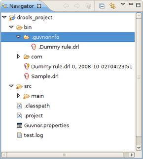
Figure 7.2. Diagram
The EGT decorates local resources associated with Guvnor repository master copies. This decoration appears in JBoss Developer Studio views conforming to the JBoss Developer Studio Common Navigator framework, such as the JBoss Developer Studio Resource Navigator and the Java Package Explorer. TheDummy rule.drlfile with the decoration in the Resource Navigator. The Guvnor icon decorator is on the top right of the file image, and the Guvnor revision details are appended to the file name. You can change the location of these in the Local Guvnor Repository Resource Decoration Preferences. - You can see that the
Dummy rule.drlfile is associated with a Guvnor repository resource, and the local copy is based on revision 0, with a02-10-2008, 4:21:53date/time stamp. However, the fileSample.drlis not associated with a Guvnor repository file. - The EGT adds a property page to the standard JBoss Developer Studio properties dialog. Use it to view the specific Guvnor repository, the location within the repository, the version (date/time stamp) and the revision number.
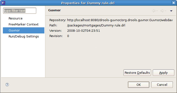
Figure 7.3. Properties
7.5. Managing Guvnor Resources
- Update Action
- Available for Guvnor resources that are not synchronized with the Guvnor repository master copies. These resources may not have synchronized due to local changes and/or changes to the master copy. Performing the Update action replaces the local file contents with the current contents from the Guvnor repository master copies.
- Add Action
- Available for local files that are not associated with a Guvnor repository master copy. Choosing the Add action launches the Add in Guvnor wizard. The first page of the wizard asks for the selection of the target Guvnor repository and provides the option of creating a new Guvnor repository connection. Once the target Guvnor repository is chosen, the wizard asks for the folder location to add the selection files. Clicking on the Finish button adds the selected files to the Guvnor repository and creates an association between the local and Guvnor repository files.
Note
The snapshot folder in the Guvnor repository is read-only for EGT, and hence not visible as a candidate location in this wizard. The Guvnor repository web administration tools must be used to add snapshot content.Note
The wizard does not allow existing Guvnor repository files to be overwritten. Another target location must be chosen. - Commit Action
- Enabled for Guvnor repository associated files that have local changes. The Commit action writes the changes back to the associated Guvnor repository files and update the association for the new revision created.If a local change is based on an older revision of a file than is currently in the Guvnor repository, the Commit action asks whether you wish to overwrite the current version in the Guvnor repository with the local content. When such conflicts occur, you should use the JBoss Developer Studio Guvnor version tools and the JBoss Developer Studio standard tools to determine the differences and merge content based on the current version.
- Show History Action
- Populates the Guvnor Resource History View with revision history for the selected file.
- Compare with Version Action
- Enabled for singular Guvnor repository associated files. This action first opens a wizard asking for the version for comparison (with the local file contents). Once the revision is selected, the action opens the JBoss Developer Studio Compare editor (in a read-only mode) which shows the differences in the two versions.
- Switch to Version Action
- Enabled for singular Guvnor repository associated files. It first prompts for the selection of a version. Once the version is selected, the Switch to Version action replaces the local file contents with those from the revision selected.
- Delete Action
- Enabled for one or more Guvnor repository associated files. After the action has been confirmed, the Delete action removes the files in the Guvnor repository and deletes local metadata for the Guvnor repository association.
- Disconnect Action
- Enabled for one or more Guvnor repository associated files. Removes local metadata from the Guvnor repository association.
7.6. Resource from Guvnor Wizard
- Open the wizard by selecting → → → or → → → → .
- You are prompted to enter the source Guvnor repository. You can also create a new Guvnor repository connection.
- Once the source Guvnor repository is chosen, the wizard prompts for the resources to be copied.
- Finally, choose the target location for the files in the local workspace.
- On completion the wizard copies the selected files from the Guvnor repository to the local workspace. If a file with the same name already exists in the destination, you are prompted to rename it.
7.7. Guvnor Repositories View
Table 7.1. Guvnor Repositories View Actions
| Action | Description |
|---|---|
| Create a new Guvnor repository connection | Use the wizard to create a new connection by selecting → → → → in JBoss Developer Studio. |
| Remove a Guvnor repository connection | Click (
 ) to remove a repository connection.
 |
| Refresh Guvnor repository resources. | Use the context menu item to reload the tree for the selected node. |
| "Drill-into" functionality | Use icons on the toolbar such as the , and buttons to navigate deeply nested structures. |
button (
 )
) | Returns the tree to the top-level structure. |
| Selecting a file in the Guvnor repository | Doing this causes the JBoss Developer Studio Properties view to display the details of that file. |
7.8. Guvnor Resource History View
7.9. Configuring the Guvnor Resource History View
- Select Show History in the local Guvnor context menu. Alternatively, select it in the context menu for a Guvnor repository file in the Guvnor Repositories View.
- The Guvnor Resource History view is refreshed to display the revision history.
- To open a JBoss Developer Studio read-only editor with the revision contents, double-click on a revision row or select the option from the context menu.
- Click on the option when a file is open in a read-only editor to save a local writable copy of the contents. (This does not associate the file created with its Guvnor source.)
7.10. Guvnor Preferences
- Guvnor repository connections
- Local Guvnor repository resource decorations
7.11. Guvnor Repository Connection Preferences
Table 7.2. Guvnor Repository Connection Preferences
| Preference | Description |
|---|---|
| Default Guvnor repository URL template | Simplifies the process of creating additional similar connections by changing part of the field, such as the host name. |
| Authentication information | Defines whether or not authentication information should be saved in the JBoss Developer Studio platform key-ring by default. As with the Guvnor repository URL template, this decision can be determined when creating the connection. |
7.12. Local Guvnor Repository Resource Decoration Preferences
- Whether to show an indicator (>) when the local file has changes not committed back to the Guvnor repository
- Whether to show the revision number
- Whether to show the date/time stamp
Appendix A. Revision History
| Revision History | |||
|---|---|---|---|
| Revision 6.0.0-27 | Monday February 23 2015 | ||
| |||
| Revision 6.0.0-26 | Tuesday January 13 2015 | ||
| |||
| Revision 6.0.0-25 | Wednesday December 17 2014 | ||
|
| |||