
Red Hat Training
A Red Hat training course is available for Red Hat Enterprise Linux
Virtualization Deployment and Administration Guide
Installing, configuring, and managing virtual machines on a RHEL physical machine
Abstract
Important
Part I. Deployment
Chapter 1. System Requirements
1.1. Host System Requirements
Minimum host system requirements
- 6 GB free disk space.
- 2 GB RAM.
Recommended system requirements
- One core or thread for each virtualized CPU and one for the host.
- 2 GB of RAM, plus additional RAM for virtual machines.
- 6 GB disk space for the host, plus the required disk space for the virtual machine(s).Most guest operating systems require at least 6 GB of disk space. Additional storage space for each guest depends on their workload.
Swap space
Swap space in Linux is used when the amount of physical memory (RAM) is full. If the system needs more memory resources and the RAM is full, inactive pages in memory are moved to the swap space. While swap space can help machines with a small amount of RAM, it should not be considered a replacement for more RAM. Swap space is located on hard drives, which have a slower access time than physical memory. The size of your swap partition can be calculated from the physical RAM of the host. The Red Hat Customer Portal contains an article on safely and efficiently determining the size of the swap partition: https://access.redhat.com/site/solutions/15244.- When using raw image files, the total disk space required is equal to or greater than the sum of the space required by the image files, the 6 GB of space required by the host operating system, and the swap space for the guest.
Equation 1.1. Calculating required space for guest virtual machines using raw images
total for raw format = images + hostspace + swapFor qcow images, you must also calculate the expected maximum storage requirements of the guest(total for qcow format), as qcow and qcow2 images are able to grow as required. To allow for this expansion, first multiply the expected maximum storage requirements of the guest(expected maximum guest storage)by 1.01, and add to this the space required by the host(host), and the necessary swap space(swap).Equation 1.2. Calculating required space for guest virtual machines using qcow images
total for qcow format = (expected maximum guest storage * 1.01) + host + swap
1.2. KVM Hypervisor Requirements
- an Intel processor with the Intel VT-x and Intel 64 virtualization extensions for x86-based systems; or
- an AMD processor with the AMD-V and the AMD64 virtualization extensions.
Procedure 1.1. Verifying virtualization extensions
Verify the CPU virtualization extensions are available
enter the following command to verify the CPU virtualization extensions are available:$
grep -E 'svm|vmx' /proc/cpuinfoAnalyze the output
- The following example output contains a
vmxentry, indicating an Intel processor with the Intel VT-x extension:flags : fpu tsc msr pae mce cx8
vmxapic mtrr mca cmov pat pse36 clflush dts acpi mmx fxsr sse sse2 ss ht tm syscall lm constant_tsc pni monitor ds_cpl vmx est tm2 cx16 xtpr lahf_lm - The following example output contains an
svmentry, indicating an AMD processor with the AMD-V extensions:flags : fpu tsc msr pae mce cx8 apic mtrr mca cmov pat pse36 clflush mmx fxsr sse sse2 ht syscall nx mmxext
svmfxsr_opt lm 3dnowext 3dnow pni cx16 lahf_lm cmp_legacy svm cr8legacy ts fid vid ttp tm stc
If thegrep -E 'svm|vmx' /proc/cpuinfocommand returns any output, the processor contains the hardware virtualization extensions. In some circumstances, manufacturers disable the virtualization extensions in the BIOS. If the extensions do not appear, or full virtualization does not work, see Procedure A.3, “Enabling virtualization extensions in BIOS” for instructions on enabling the extensions in your BIOS configuration utility.Ensure the KVM kernel modules are loaded
As an additional check, verify that thekvmmodules are loaded in the kernel with the following command:#
lsmod | grep kvmIf the output includeskvm_intelorkvm_amd, thekvmhardware virtualization modules are loaded.
Note
virsh utility (provided by the libvirt-client package) can output a full list of your system's virtualization capabilities with the following command:
# virsh capabilities1.3. KVM Guest Virtual Machine Compatibility
- For host systems: https://access.redhat.com/articles/rhel-limits
- For the KVM hypervisor: https://access.redhat.com/articles/rhel-kvm-limits
Note
1.4. Supported Guest CPU Models
1.4.1. Listing the Guest CPU Models
virsh cpu-models architecture command. For example:
$ virsh cpu-models x86_64
486
pentium
pentium2
pentium3
pentiumpro
coreduo
n270
core2duo
qemu32
kvm32
cpu64-rhel5
cpu64-rhel6
kvm64
qemu64
Conroe
Penryn
Nehalem
Westmere
SandyBridge
Haswell
athlon
phenom
Opteron_G1
Opteron_G2
Opteron_G3
Opteron_G4
Opteron_G5
$ virsh cpu-models ppc64
POWER7
POWER7_v2.1
POWER7_v2.3
POWER7+_v2.1
POWER8_v1.0
cpu_map.xml file, located in /usr/share/libvirt/:
# cat /usr/share/libvirt/cpu_map.xml<cpu> section of the domain XML file. See Section 23.12, “CPU Models and Topology” for more information.
Chapter 2. Installing the Virtualization Packages
yum command and the Subscription Manager application.
kvm kernel module.
2.1. Installing Virtualization Packages During a Red Hat Enterprise Linux Installation
Note
Important
Procedure 2.1. Installing virtualization packages
Select software
Follow the installation procedure until the Installation Summary screen.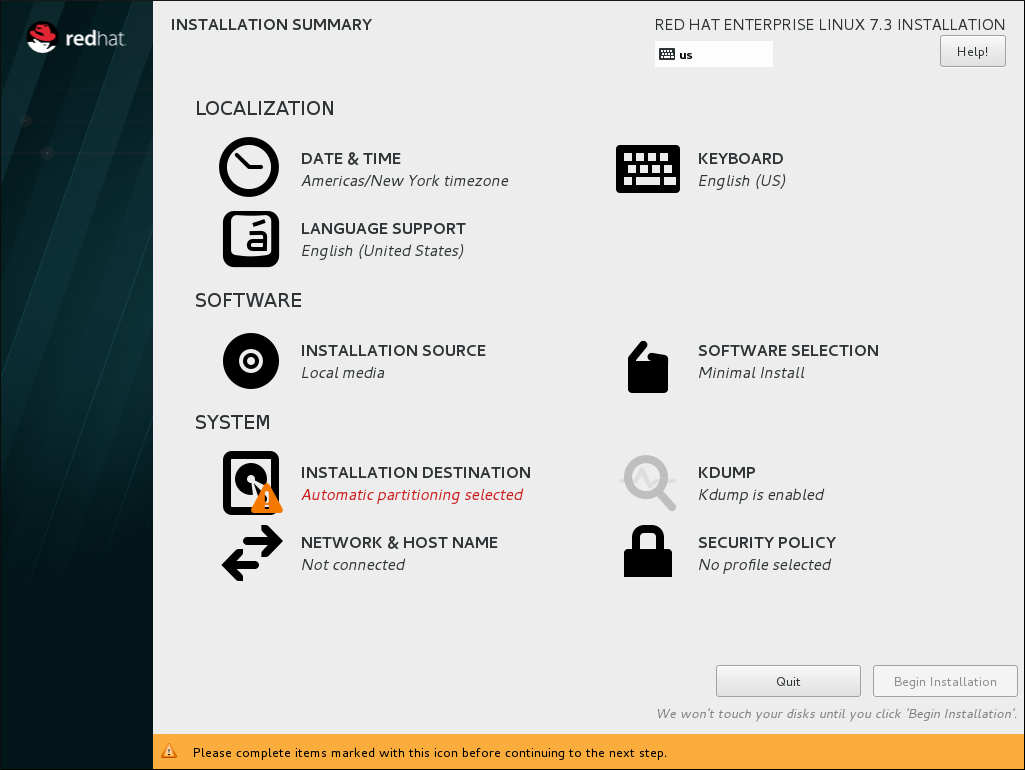
Figure 2.1. The Installation Summary screen
In the Installation Summary screen, click Software Selection. The Software Selection screen opens.Select the server type and package groups
You can install Red Hat Enterprise Linux 7 with only the basic virtualization packages or with packages that allow management of guests through a graphical user interface. Do one of the following:- Install a minimal virtualization hostSelect the Virtualization Host radio button in the Base Environment pane and the Virtualization Platform check box in the Add-Ons for Selected Environment pane. This installs a basic virtualization environment which can be run with
virshor remotely over the network.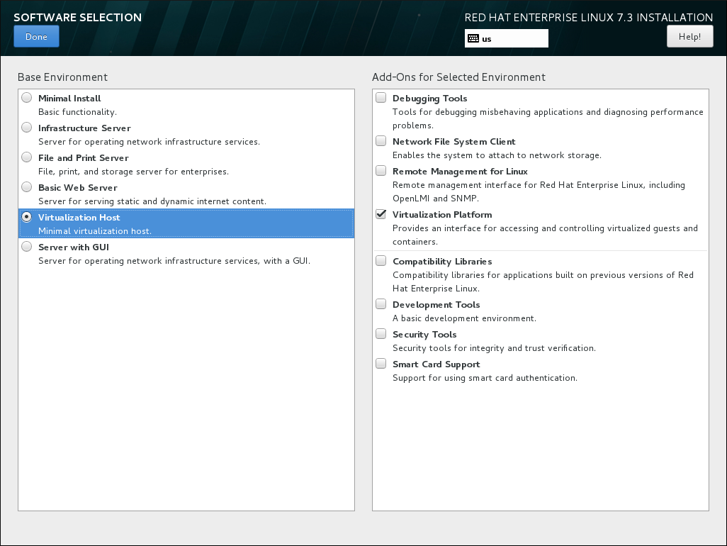
Figure 2.2. Virtualization Host selected in the Software Selection screen
- Install a virtualization host with a graphical user interfaceSelect the Server with GUI radio button in the Base Environment pane and the Virtualization Client, Virtualization Hypervisor, and Virtualization Tools check boxes in the Add-Ons for Selected Environment pane. This installs a virtualization environment along with graphical tools for installing and managing guest virtual machines.
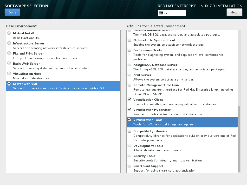
Figure 2.3. Server with GUI selected in the software selection screen
Finalize installation
Click and continue with the installation.
Important
2.1.1. Installing KVM Packages with Kickstart Files
%packages section of your Kickstart file:
@virtualization-hypervisor
@virtualization-client
@virtualization-platform
@virtualization-tools
2.2. Installing Virtualization Packages on an Existing Red Hat Enterprise Linux System
subscription-manager register command and follow the prompts. Alternatively, run the Red Hat Subscription Manager application from → on the desktop to register.
2.2.1. Installing Virtualization Packages Manually
- qemu-kvm: This package provides the user-level KVM emulator and facilitates communication between hosts and guest virtual machines.
- qemu-img: This package provides disk management for guest virtual machines.
Note
The qemu-img package is installed as a dependency of the qemu-kvm package. - libvirt: This package provides the server and host-side libraries for interacting with hypervisors and host systems, and the
libvirtddaemon that handles the library calls, manages virtual machines, and controls the hypervisor.
# yum install qemu-kvm libvirt- virt-install: This package provides the
virt-installcommand for creating virtual machines from the command line. - libvirt-python: This package contains a module that permits applications written in the Python programming language to use the interface supplied by the libvirt API.
- virt-manager: This package provides the virt-manager tool, also known as Virtual Machine Manager. This is a graphical tool for administering virtual machines. It uses the libvirt-client library as the management API.
- libvirt-client: This package provides the client-side APIs and libraries for accessing libvirt servers. The libvirt-client package includes the
virshcommand-line tool to manage and control virtual machines and hypervisors from the command line or a special virtualization shell.
# yum install virt-install libvirt-python virt-manager virt-install libvirt-client2.2.2. Installing Virtualization Package Groups
yum grouplist hidden commad.
Table 2.1. Virtualization Package Groups
| Package Group | Description | Mandatory Packages | Optional Packages |
|---|---|---|---|
Virtualization Hypervisor | Smallest possible virtualization host installation | libvirt, qemu-kvm, qemu-img | qemu-kvm-tools |
Virtualization Client | Clients for installing and managing virtualization instances | gnome-boxes, virt-install, virt-manager, virt-viewer, qemu-img | virt-top, libguestfs-tools, libguestfs-tools-c |
Virtualization Platform | Provides an interface for accessing and controlling virtual machines and containers | libvirt, libvirt-client, virt-who, qemu-img | fence-virtd-libvirt, fence-virtd-multicast, fence-virtd-serial, libvirt-cim, libvirt-java, libvirt-snmp, perl-Sys-Virt |
Virtualization Tools | Tools for offline virtual image management | libguestfs, qemu-img | libguestfs-java, libguestfs-tools, libguestfs-tools-c |
yum group install package_group command. For example, to install the Virtualization Tools package group with all the package types, run:
# yum group install "Virtualization Tools" --setopt=group_package_types=mandatory,default,optionalChapter 3. Creating a Virtual Machine
virt-install command-line utility by a list of parameters or with a script. Both methods are covered by this chapter.
3.1. Guest Virtual Machine Deployment Considerations
- Performance
- Guest virtual machines should be deployed and configured based on their intended tasks. Some guest systems (for instance, guests running a database server) may require special performance considerations. Guests may require more assigned CPUs or memory based on their role and projected system load.
- Input/Output requirements and types of Input/Output
- Some guest virtual machines may have a particularly high I/O requirement or may require further considerations or projections based on the type of I/O (for instance, typical disk block size access, or the amount of clients).
- Storage
- Some guest virtual machines may require higher priority access to storage or faster disk types, or may require exclusive access to areas of storage. The amount of storage used by guests should also be regularly monitored and taken into account when deploying and maintaining storage. Make sure to read all the considerations outlined in Red Hat Enterprise Linux 7 Virtualization Security Guide. It is also important to understand that your physical storage may limit your options in your virtual storage.
- Networking and network infrastructure
- Depending upon your environment, some guest virtual machines could require faster network links than other guests. Bandwidth or latency are often factors when deploying and maintaining guests, especially as requirements or load changes.
- Request requirements
- SCSI requests can only be issued to guest virtual machines on virtio drives if the virtio drives are backed by whole disks, and the disk device parameter is set to
lunin the domain XML file, as shown in the following example:<devices> <emulator>/usr/libexec/qemu-kvm</emulator> <disk type='block' device='lun'>
3.2. Creating Guests with virt-install
virt-install command to create virtual machines and install operating system on those virtual machines from the command line. virt-install can be used either interactively or as part of a script to automate the creation of virtual machines. If you are using an interactive graphical installation, you must have virt-viewer installed before you run virt-install. In addition, you can start an unattended installation of virtual machine operating systems using virt-install with kickstart files.
Note
virt-install commands to complete successfully.
virt-install utility uses a number of command-line options. However, most virt-install options are not required.
--name- The name of the virtual machine.
--memory- The amount of memory (RAM) to allocate to the guest, in MiB.
- Guest storage
- Use one of the following guest storage options:
--diskThe storage configuration details for the virtual machine. If you use the--disk noneoption, the virtual machine is created with no disk space.--filesystemThe path to the file system for the virtual machine guest.
- Installation method
- Use one of the following installation methods:
--locationThe location of the installation media.--cdromThe file or device used as a virtual CD-ROM device. It can be path to an ISO image, or a URL from which to fetch or access a minimal boot ISO image. However, it can not be a physical host CD-ROM or DVD-ROM device.--pxeUses the PXE boot protocol to load the initial ramdisk and kernel for starting the guest installation process.--importSkips the OS installation process and builds a guest around an existing disk image. The device used for booting is the first device specified by thediskorfilesystemoption.--bootThe post-install VM boot configuration. This option allows specifying a boot device order, permanently booting off kernel and initrd with optional kernel arguments and enabling a BIOS boot menu.
# virt-install --help# virt install --option=?virt-install man page also documents each command option, important variables, and examples.
virt-install, you may also need to use qemu-img to configure storage options. For instructions on using qemu-img, see Chapter 14, Using qemu-img.
3.2.1. Installing a virtual machine from an ISO image
#virt-install \--name guest1-rhel7 \--memory 2048 \--vcpus 2 \--disk size=8 \--cdrom /path/to/rhel7.iso \--os-variant rhel7
--cdrom /path/to/rhel7.iso option specifies that the virtual machine will be installed from the CD or DVD image at the specified location.
3.2.2. Importing a virtual machine image
#virt-install \--name guest1-rhel7 \--memory 2048 \--vcpus 2 \--disk /path/to/imported/disk.qcow \--import \--os-variant rhel7
--import option specifies that the virtual machine will be imported from the virtual disk image specified by the --disk /path/to/imported/disk.qcow option.
3.2.3. Installing a virtual machine from the network
#virt-install \--name guest1-rhel7 \--memory 2048 \--vcpus 2 \--disk size=8 \--location http://example.com/path/to/os \--os-variant rhel7
--location http://example.com/path/to/os option specifies that the installation tree is at the specified network location.
3.2.4. Installing a virtual machine using PXE
--network option specifying a bridged network and the --pxe option must be specified.
#virt-install \--name guest1-rhel7 \--memory 2048 \--vcpus 2 \--disk size=8 \--network=bridge:br0 \--pxe \--os-variant rhel7
3.2.5. Installing a virtual machine with Kickstart
#virt-install \--name guest1-rhel7 \--memory 2048 \--vcpus 2 \--disk size=8 \--location http://example.com/path/to/os \--os-variant rhel7 \--initrd-inject /path/to/ks.cfg \--extra-args="ks=file:/ks.cfg console=tty0 console=ttyS0,115200n8"
initrd-inject and the extra-args options specify that the virtual machine will be installed using a Kickstarter file.
3.2.6. Configuring the guest virtual machine network during guest creation
Default network with NAT
libvirtd's network address translation (NAT) virtual network switch. For more information about NAT, see Section 6.1, “Network Address Translation (NAT) with libvirt”.
virt-install:
--network defaultNote
network option is specified, the guest virtual machine is configured with a default network with NAT.
Bridged network with DHCP
--network br0Note
virt-install. For details on creating a network bridge, see Section 6.4.1, “Configuring Bridged Networking on a Red Hat Enterprise Linux 7 Host”.
Bridged network with a static IP address
--network br0 \--extra-args "ip=192.168.1.2::192.168.1.1:255.255.255.0:test.example.com:eth0:none"
No network
--network=none3.3. Creating Guests with virt-manager
virt-manager, is a graphical tool for creating and managing guest virtual machines.
3.3.1. virt-manager installation overview
- Choosing the hypervisor and installation type
- Locating and configuring the installation media
- Configuring memory and CPU options
- Configuring the virtual machine's storage
- Configuring virtual machine name, networking, architecture, and other hardware settings
virt-manager can access the installation media (whether locally or over the network) before you continue.
3.3.2. Creating a Red Hat Enterprise Linux 7 Guest with virt-manager
Note
Procedure 3.1. Creating a Red Hat Enterprise Linux 7 guest virtual machine with virt-manager using local installation media
Optional: Preparation
Prepare the storage environment for the virtual machine. For more information on preparing storage, see Chapter 13, Managing Storage for Virtual Machines.Important
Various storage types may be used for storing guest virtual machines. However, for a virtual machine to be able to use migration features, the virtual machine must be created on networked storage.Red Hat Enterprise Linux 7 requires at least 1 GB of storage space. However, Red Hat recommends at least 5 GB of storage space for a Red Hat Enterprise Linux 7 installation and for the procedures in this guide.Open virt-manager and start the wizard
Open virt-manager by executing thevirt-managercommand as root or opening Applications → System Tools → Virtual Machine Manager.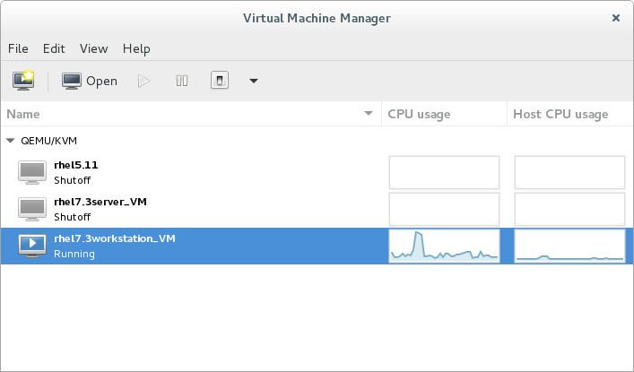
Figure 3.1. The Virtual Machine Manager window
Optionally, open a remote hypervisor by selecting the hypervisor and clicking the button.Click to start the new virtualized guest wizard.
The New VM window opens.
to start the new virtualized guest wizard.
The New VM window opens.Specify installation type
Select the installation type:- Local install media (ISO image or CDROM)
- This method uses an image of an installation disk (for example,
.iso). However, using a host CD-ROM or a DVD-ROM device is not possible. - Network Install (HTTP, FTP, or NFS)
- This method involves the use of a mirrored Red Hat Enterprise Linux or Fedora installation tree to install a guest. The installation tree must be accessible through either HTTP, FTP, or NFS.If you select Network Install, provide the installation URL and also Kernel options, if required.
- Network Boot (PXE)
- This method uses a Preboot eXecution Environment (PXE) server to install the guest virtual machine. Setting up a PXE server is covered in the Red Hat Enterprise Linux 7 Installation Guide. To install using network boot, the guest must have a routable IP address or shared network device.If you select Network Boot, continue to STEP 5. After all steps are completed, a DHCP request is sent and if a valid PXE server is found the guest virtual machine's installation processes will start.
- Import existing disk image
- This method allows you to create a new guest virtual machine and import a disk image (containing a pre-installed, bootable operating system) to it.
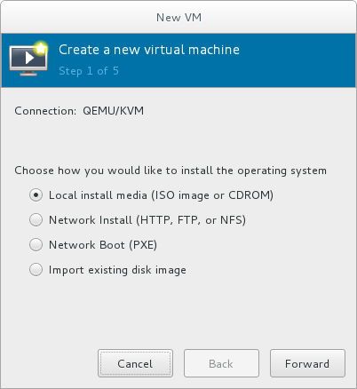
Figure 3.2. Virtual machine installation method
Click to continue.Select the installation source
- If you selected Local install media (ISO image or CDROM), specify your intended local installation media.

Figure 3.3. Local ISO image installation
Warning
Even though the option is currently present in the GUI, installing from a physical CD-ROM or DVD device on the host is not possible. Therefore, selecting the Use CDROM or DVD option will cause the VM installation to fail. For details, see the Red Hat Knowledge Base.To install from an ISO image, select Use ISO image and click the button to open the Locate media volume window.Select the installation image you wish to use, and click .If no images are displayed in the Locate media volume window, click the button to browse the host machine for the installation image or DVD drive containing the installation disk. Select the installation image or DVD drive containing the installation disk and click ; the volume is selected for use and you are returned to the Create a new virtual machine wizard.Important
For ISO image files and guest storage images, the recommended location to use is/var/lib/libvirt/images/. Any other location may require additional configuration by SELinux. See the Red Hat Enterprise Linux Virtualization Security Guide or the Red Hat Enterprise Linux SELinux User's and Administrator's Guide for more details on configuring SELinux. - If you selected
Network Install, input the URL of the installation source and also the required Kernel options, if any. The URL must point to the root directory of an installation tree, which must be accessible through either HTTP, FTP, or NFS.To perform a kickstart installation, specify the URL of a kickstart file in Kernel options, starting withks=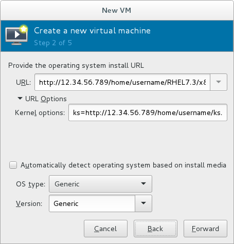
Figure 3.4. Network kickstart installation
Note
For a complete list of kernel options, see the Red Hat Enterprise Linux 7 Installation Guide.
Next, configure the and of the installation. Ensure that you select the appropriate operating system type for your virtual machine. This can be specified manually or by selecting the Automatically detect operating system based on install media check box.Click to continue.Configure memory (RAM) and virtual CPUs
Specify the number of CPUs and amount of memory (RAM) to allocate to the virtual machine. The wizard shows the number of CPUs and amount of memory you can allocate; these values affect the host's and guest's performance.Virtual machines require sufficient physical memory (RAM) to run efficiently and effectively. Red Hat supports a minimum of 512MB of RAM for a virtual machine. Red Hat recommends at least 1024MB of RAM for each logical core.Assign sufficient virtual CPUs for the virtual machine. If the virtual machine runs a multi-threaded application, assign the number of virtual CPUs the guest virtual machine will require to run efficiently.You cannot assign more virtual CPUs than there are physical processors (or hyper-threads) available on the host system. The number of virtual CPUs available is noted in the Up to X available field.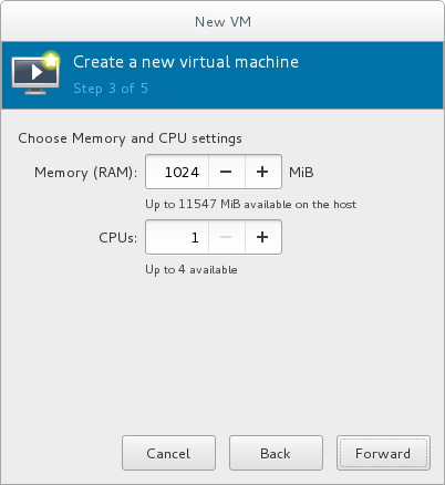
Figure 3.5. Configuring Memory and CPU
After you have configured the memory and CPU settings, click to continue.Note
Memory and virtual CPUs can be overcommitted. For more information on overcommitting, see Chapter 7, Overcommitting with KVM.Configure storage
Enable and assign sufficient space for your virtual machine and any applications it requires. Assign at least 5 GB for a desktop installation or at least 1 GB for a minimal installation.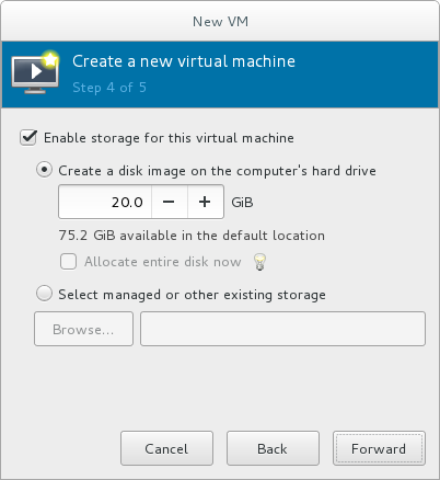
Figure 3.6. Configuring virtual storage
Note
Live and offline migrations require virtual machines to be installed on shared network storage. For information on setting up shared storage for virtual machines, see Section 15.4, “Shared Storage Example: NFS for a Simple Migration”.With the default local storage
Select the Create a disk image on the computer's hard drive radio button to create a file-based image in the default storage pool, the/var/lib/libvirt/images/directory. Enter the size of the disk image to be created. If the Allocate entire disk now check box is selected, a disk image of the size specified will be created immediately. If not, the disk image will grow as it becomes filled.Note
Although the storage pool is a virtual container it is limited by two factors: maximum size allowed to it by qemu-kvm and the size of the disk on the host physical machine. Storage pools may not exceed the size of the disk on the host physical machine. The maximum sizes are as follows:- virtio-blk = 2^63 bytes or 8 Exabytes(using raw files or disk)
- Ext4 = ~ 16 TB (using 4 KB block size)
- XFS = ~8 Exabytes
- qcow2 and host file systems keep their own metadata and scalability should be evaluated/tuned when trying very large image sizes. Using raw disks means fewer layers that could affect scalability or max size.
Click to create a disk image on the local hard drive. Alternatively, select Select managed or other existing storage, then select Browse to configure managed storage.With a storage pool
If you select Select managed or other existing storage to use a storage pool, click Browse to open the Locate or create storage volume window.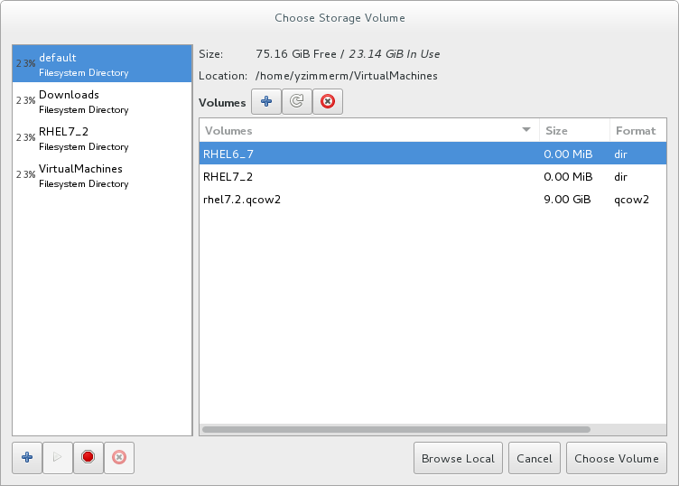
Figure 3.7. The Choose Storage Volume window
- Select a storage pool from the Storage Pools list.
- Optional: Click
 to create a new storage volume. The Add a Storage Volume screen will appear. Enter the name of the new storage volume.
Choose a format option from the Format drop-down menu. Format options include raw, qcow2, and qed. Adjust other fields as needed. Note that the qcow2 version used here is version 3. To change the qcow version see Section 23.19.2, “Setting Target Elements”
to create a new storage volume. The Add a Storage Volume screen will appear. Enter the name of the new storage volume.
Choose a format option from the Format drop-down menu. Format options include raw, qcow2, and qed. Adjust other fields as needed. Note that the qcow2 version used here is version 3. To change the qcow version see Section 23.19.2, “Setting Target Elements”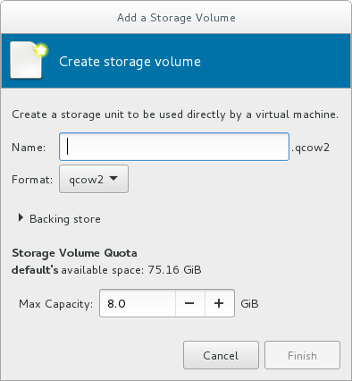
Figure 3.8. The Add a Storage Volume window
Select the new volume and click . Next, click to return to the New VM wizard. Click to continue.Name and final configuration
Name the virtual machine. Virtual machine names can contain letters, numbers and the following characters: underscores (_), periods (.), and hyphens (-). Virtual machine names must be unique for migration and cannot consist only of numbers.By default, the virtual machine will be created with network address translation (NAT) for a network called 'default' . To change the network selection, clickNetwork selectionand select a host device and source mode.Verify the settings of the virtual machine and click when you are satisfied; this will create the virtual machine with specified networking settings, virtualization type, and architecture.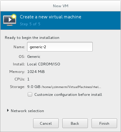
Figure 3.9. Verifying the configuration
Or, to further configure the virtual machine's hardware, check the check box to change the guest's storage or network devices, to use the paravirtualized (virtio) drivers or to add additional devices. This opens another wizard that will allow you to add, remove, and configure the virtual machine's hardware settings.Note
Red Hat Enterprise Linux 4 or Red Hat Enterprise Linux 5 guest virtual machines cannot be installed using graphical mode. As such, you must select "Cirrus" instead of "QXL" as a video card.After configuring the virtual machine's hardware, click .virt-managerwill then create the virtual machine with your specified hardware settings.Warning
When installing a Red Hat Enterprise Linux 7 guest virtual machine from a remote medium but without a configured TCP/IP connection, the installation fails. However, when installing a guest virtual machine of Red Hat Enterprise Linux 5 or 6 in such circumstances, the installer opens a "Configure TCP/IP" interface.For further information about this difference, see the related knowledgebase article.Click to continue into the Red Hat Enterprise Linux installation sequence. For more information on installing Red Hat Enterprise Linux 7, see the Red Hat Enterprise Linux 7 Installation Guide.
3.4. Comparison of virt-install and virt-manager Installation options
virt-install and virt-manager installation options for when installing a virtual machine.
virt-install options are not required. The minimum requirements are --name, --memory, guest storage (--disk, --filesystem or --disk none), and an install method (--location, --cdrom, --pxe, --import, or boot). These options are further specified with arguments; to see a complete list of command options and related arguments, enter the following command:
# virt-install --helpTable 3.1. virt-install and virt-manager configuration comparison for guest installations
| Configuration on virtual machine | virt-install option | virt-manager installation wizard label and step number |
|---|---|---|
| Virtual machine name | --name, -n | Name (step 5) |
| RAM to allocate (MiB) | --ram, -r | Memory (RAM) (step 3) |
| Storage - specify storage media | --disk | Enable storage for this virtual machine → Create a disk image on the computer's hard drive, or Select managed or other existing storage (step 4) |
| Storage - export a host directory to the guest | --filesystem | Enable storage for this virtual machine → Select managed or other existing storage (step 4) |
| Storage - configure no local disk storage on the guest | --nodisks | Deselect the Enable storage for this virtual machine check box (step 4) |
| Installation media location (local install) | --file | Local install media → Locate your install media (steps 1-2) |
| Installation using a distribution tree (network install) | --location | Network install → URL (steps 1-2) |
| Install guest with PXE | --pxe | Network boot (step 1) |
| Number of vCPUs | --vcpus | CPUs (step 3) |
| Host network | --network | Advanced options drop-down menu (step 5) |
| Operating system variant/version | --os-variant | Version (step 2) |
| Graphical display method | --graphics, --nographics | * virt-manager provides GUI installation only |
Chapter 4. Cloning Virtual Machines
- Clones are instances of a single virtual machine. Clones can be used to set up a network of identical virtual machines, and they can also be distributed to other destinations.
- Templates are instances of a virtual machine that are designed to be used as a source for cloning. You can create multiple clones from a template and make minor modifications to each clone. This is useful in seeing the effects of these changes on the system.
- Platform level information and configurations include anything assigned to the virtual machine by the virtualization solution. Examples include the number of Network Interface Cards (NICs) and their MAC addresses.
- Guest operating system level information and configurations include anything configured within the virtual machine. Examples include SSH keys.
- Application level information and configurations include anything configured by an application installed on the virtual machine. Examples include activation codes and registration information.
Note
This chapter does not include information about removing the application level, because the information and approach is specific to each application.
Note
4.1. Preparing Virtual Machines for Cloning
Procedure 4.1. Preparing a virtual machine for cloning
Setup the virtual machine
- Build the virtual machine that is to be used for the clone or template.
- Install any software needed on the clone.
- Configure any non-unique settings for the operating system.
- Configure any non-unique application settings.
Remove the network configuration
- Remove any persistent udev rules using the following command:
# rm -f /etc/udev/rules.d/70-persistent-net.rules
Note
If udev rules are not removed, the name of the first NIC may be eth1 instead of eth0. - Remove unique network details from ifcfg scripts by making the following edits to
/etc/sysconfig/network-scripts/ifcfg-eth[x]:- Remove the HWADDR and Static lines
Note
If the HWADDR does not match the new guest's MAC address, the ifcfg will be ignored. Therefore, it is important to remove the HWADDR from the file.DEVICE=eth[x] BOOTPROTO=none ONBOOT=yes #NETWORK=10.0.1.0 <- REMOVE #NETMASK=255.255.255.0 <- REMOVE #IPADDR=10.0.1.20 <- REMOVE #HWADDR=xx:xx:xx:xx:xx <- REMOVE #USERCTL=no <- REMOVE # Remove any other *unique* or non-desired settings, such as UUID.
- Ensure that a DHCP configuration remains that does not include a HWADDR or any unique information.
DEVICE=eth[x]
BOOTPROTO=dhcp
ONBOOT=yes
- Ensure that the file includes the following lines:
DEVICE=eth[x]
ONBOOT=yes
- If the following files exist, ensure that they contain the same content:
/etc/sysconfig/networking/devices/ifcfg-eth[x]/etc/sysconfig/networking/profiles/default/ifcfg-eth[x]
Note
If NetworkManager or any special settings were used with the virtual machine, ensure that any additional unique information is removed from the ifcfg scripts.
Remove registration details
- Remove registration details using one of the following:
- For Red Hat Network (RHN) registered guest virtual machines, use the following command:
#
rm /etc/sysconfig/rhn/systemid - For Red Hat Subscription Manager (RHSM) registered guest virtual machines:
- If the original virtual machine will not be used, use the following commands:
#
subscription-manager unsubscribe --all#subscription-manager unregister#subscription-manager clean - If the original virtual machine will be used, run only the following command:
#
subscription-manager cleanThe original RHSM profile remains in the Portal. To reactivate your RHSM registration on the virtual machine after it is cloned, do the following:- Obtain your customer identity code:
#
subscription-manager identitysubscription-manager identity: 71rd64fx-6216-4409-bf3a-e4b7c7bd8ac9 - Register the virtual machine using the obtained ID code:
#
subscription-manager register --consumerid=71rd64fx-6216-4409-bf3a-e4b7c7bd8ac9
Removing other unique details
- Remove any sshd public/private key pairs using the following command:
#
rm -rf /etc/ssh/ssh_host_*Note
Removing ssh keys prevents problems with ssh clients not trusting these hosts. - Remove any other application-specific identifiers or configurations that may cause conflicts if running on multiple machines.
Configure the virtual machine to run configuration wizards on the next boot
- Configure the virtual machine to run the relevant configuration wizards the next time it is booted by doing one of the following:
- For Red Hat Enterprise Linux 6 and below, create an empty file on the root file system called .unconfigured using the following command:
#
touch /.unconfigured - For Red Hat Enterprise Linux 7, enable the first boot and initial-setup wizards by running the following commands:
#
sed -ie 's/RUN_FIRSTBOOT=NO/RUN_FIRSTBOOT=YES/' /etc/sysconfig/firstboot#systemctl enable firstboot-graphical#systemctl enable initial-setup-graphical
Note
The wizards that run on the next boot depend on the configurations that have been removed from the virtual machine. In addition, on the first boot of the clone, it is recommended that you change the hostname.
4.2. Cloning a Virtual Machine
virt-clone or virt-manager.
4.2.1. Cloning Guests with virt-clone
virt-clone to clone virtual machines from the command line.
virt-clone to complete successfully.
virt-clone command provides a number of options that can be passed on the command line. These include general options, storage configuration options, networking configuration options, and miscellaneous options. Only the --original is required. To see a complete list of options, enter the following command:
# virt-clone --helpvirt-clone man page also documents each command option, important variables, and examples.
Example 4.1. Using virt-clone to clone a guest
# virt-clone --original demo --auto-cloneExample 4.2. Using virt-clone to clone a guest
# virt-clone --connect qemu:///system --original demo --name newdemo --file /var/lib/libvirt/images/newdemo.img --file /var/lib/libvirt/images/newdata.img4.2.2. Cloning Guests with virt-manager
Procedure 4.2. Cloning a Virtual Machine with virt-manager
Open virt-manager
Start virt-manager. Launch the application from the menu and submenu. Alternatively, run thevirt-managercommand as root.Select the guest virtual machine you want to clone from the list of guest virtual machines in Virtual Machine Manager.Right-click the guest virtual machine you want to clone and select . The Clone Virtual Machine window opens.
Figure 4.1. Clone Virtual Machine window
Configure the clone
- To change the name of the clone, enter a new name for the clone.
- To change the networking configuration, click Details.Enter a new MAC address for the clone.Click OK.

Figure 4.2. Change MAC Address window
- For each disk in the cloned guest virtual machine, select one of the following options:
Clone this disk- The disk will be cloned for the cloned guest virtual machineShare disk with guest virtual machine name- The disk will be shared by the guest virtual machine that will be cloned and its cloneDetails- Opens the Change storage path window, which enables selecting a new path for the disk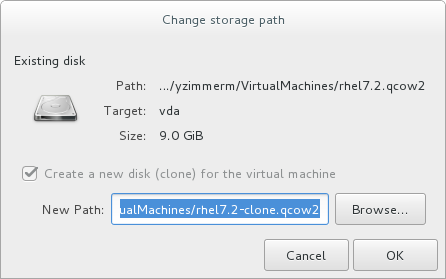
Figure 4.3. Change
storage pathwindow
Clone the guest virtual machine
Click Clone.
Chapter 5. KVM Paravirtualized (virtio) Drivers
virtio package. The virtio package supports block (storage) devices and network interface controllers.
Note
5.1. Using KVM virtio Drivers for Existing Storage Devices
virtio driver instead of the virtualized IDE driver. The example shown in this section edits libvirt configuration files. Note that the guest virtual machine does not need to be shut down to perform these steps, however the change will not be applied until the guest is completely shut down and rebooted.
Procedure 5.1. Using KVM virtio drivers for existing devices
- Ensure that you have installed the appropriate driver (
viostor), before continuing with this procedure. - Run the
virsh edit guestnamecommand as root to edit the XML configuration file for your device. For example,virsh edit guest1. The configuration files are located in the/etc/libvirt/qemu/directory. - Below is a file-based block device using the virtualized IDE driver. This is a typical entry for a virtual machine not using the virtio drivers.
<disk type='file' device='disk'>
	 ...
   <source file='/var/lib/libvirt/images/disk1.img'/>
   <target dev='hda' bus='ide'/>
	 <address type='pci' domain='0x0000' bus='0x00' slot='0x07' function='0x0'/>
</disk>
- Change the entry to use the virtio device by modifying the bus= entry to
virtio. Note that if the disk was previously IDE, it has a target similar tohda,hdb, orhdc. When changing to bus=virtio the target needs to be changed tovda,vdb, orvdcaccordingly.<disk type='file' device='disk'> ... <source file='/var/lib/libvirt/images/disk1.img'/> <target dev='vda' bus='virtio'/> <address type='pci' domain='0x0000' bus='0x00' slot='0x07' function='0x0'/> </disk>
- Remove the address tag inside the disk tags. This must be done for this procedure to work. Libvirt will regenerate the address tag appropriately the next time the virtual machine is started.
virt-manager, virsh attach-disk or virsh attach-interface can add a new device using the virtio drivers.
5.2. Using KVM virtio Drivers for New Storage Devices
virt-manager.
virsh attach-disk or virsh attach-interface commands can be used to attach devices using the virtio drivers.
Important
Procedure 5.2. Adding a storage device using the virtio storage driver
- Open the guest virtual machine by double clicking the name of the guest in
virt-manager. - Open the Show virtual hardware details tab by clicking
 .
.
- In the Show virtual hardware details tab, click the Add Hardware button.
Select hardware type
Select Storage as the Hardware type.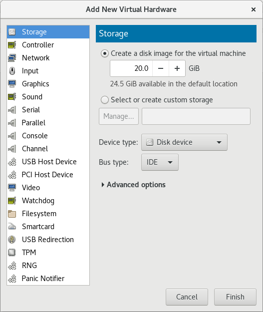
Figure 5.1. The Add new virtual hardware wizard
Select the storage device and driver
Create a new disk image or select a storage pool volume.Set the Device type to Disk device and the Bus type to VirtIO to use the virtio drivers.
Figure 5.2. The Add New Virtual Hardware wizard
Click Finish to complete the procedure.
Procedure 5.3. Adding a network device using the virtio network driver
- Open the guest virtual machine by double clicking the name of the guest in
virt-manager. - Open the Show virtual hardware details tab by clicking
.
- In the Show virtual hardware details tab, click the Add Hardware button.
Select hardware type
Select Network as the Hardware type.
Figure 5.3. The Add new virtual hardware wizard
Select the network device and driver
Set the Device model to virtio to use the virtio drivers. Choose the required Host device.
Figure 5.4. The Add new virtual hardware wizard
Click Finish to complete the procedure.
5.3. Using KVM virtio Drivers for Network Interface Devices
- To attach a virtio network device to a guest, use the
virsh attach-interfacecommand with themodel --virtiooption.Alternatively, in the virt-manager interface, navigate to the guest's Virtual hardware details screen and click . In the Add New Virtual Hardware screen, select Network, and change Device model tovirtio:
- To change the type of an existing interface to virtio, use the
virsh editcommand to edit the XML configuration of the intended guest, and change themodel typeattribute tovirtio, for example as follows:<devices> <interface type='network'> <source network='default'/> <target dev='vnet1'/> <model type='virtio'/> <driver name='vhost' txmode='iothread' ioeventfd='on' event_idx='off'/> </interface> </devices> ...Alternatively, in the virt-manager interface, navigate to the guest's Virtual hardware details screen, select theNICitem, and change Device model tovirtio: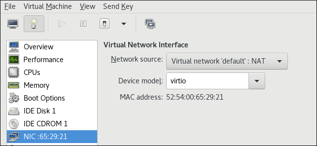
Note
virtio-net. For details, see the Red Hat Knowledgebase.
Chapter 6. Network Configuration
- virtual networks using Network Address Translation (NAT)
- directly allocated physical devices using PCI device assignment
- directly allocated virtual functions using PCIe SR-IOV
- bridged networks
6.1. Network Address Translation (NAT) with libvirt
Every standard libvirt installation provides NAT-based connectivity to virtual machines as the default virtual network. Verify that it is available with the virsh net-list --all command.
# virsh net-list --all
Name State Autostart
-----------------------------------------
default active yes
# ll /etc/libvirt/qemu/
total 12
drwx------. 3 root root 4096 Nov 7 23:02 networks
-rw-------. 1 root root 2205 Nov 20 01:20 r6.4.xml
-rw-------. 1 root root 2208 Nov 8 03:19 r6.xml
/etc/libvirt/qemu/networks/default.xml
# virsh net-autostart default
Network default marked as autostarted# virsh net-start default
Network default startedlibvirt default network is running, you will see an isolated bridge device. This device does not have any physical interfaces added. The new device uses NAT and IP forwarding to connect to the physical network. Do not add new interfaces.
# brctl show
bridge name bridge id STP enabled interfaces
virbr0 8000.000000000000 yeslibvirt adds iptables rules which allow traffic to and from guest virtual machines attached to the virbr0 device in the INPUT, FORWARD, OUTPUT and POSTROUTING chains. libvirt then attempts to enable the ip_forward parameter. Some other applications may disable ip_forward, so the best option is to add the following to /etc/sysctl.conf.
net.ipv4.ip_forward = 1
Once the host configuration is complete, a guest virtual machine can be connected to the virtual network based on its name. To connect a guest to the 'default' virtual network, the following can be used in the XML configuration file (such as /etc/libvirtd/qemu/myguest.xml) for the guest:
<interface type='network'> <source network='default'/> </interface>
Note
<interface type='network'> <source network='default'/> <mac address='00:16:3e:1a:b3:4a'/> </interface>
6.2. Disabling vhost-net
vhost-net module is a kernel-level back end for virtio networking that reduces virtualization overhead by moving virtio packet processing tasks out of user space (the QEMU process) and into the kernel (the vhost-net driver). vhost-net is only available for virtio network interfaces. If the vhost-net kernel module is loaded, it is enabled by default for all virtio interfaces, but can be disabled in the interface configuration if a particular workload experiences a degradation in performance when vhost-net is in use.
vhost-net causes the UDP socket's receive buffer to overflow more quickly, which results in greater packet loss. It is therefore better to disable vhost-net in this situation to slow the traffic, and improve overall performance.
vhost-net, edit the <interface> sub-element in the guest virtual machine's XML configuration file and define the network as follows:
<interface type="network"> ... <model type="virtio"/> <driver name="qemu"/> ... </interface>
qemu forces packet processing into QEMU user space, effectively disabling vhost-net for that interface.
6.3. Enabling vhost-net zero-copy
vhost-net.conf to /etc/modprobe.d with the following content:
options vhost_net experimental_zcopytx=1
modprobe -r vhost_net
modprobe vhost_net experimental_zcopytx=0
cat /sys/module/vhost_net/parameters/experimental_zcopytx. It should show:
$ cat /sys/module/vhost_net/parameters/experimental_zcopytx
0
6.4. Bridged Networking
6.4.1. Configuring Bridged Networking on a Red Hat Enterprise Linux 7 Host
6.4.2. Bridged Networking with Virtual Machine Manager
Note
Procedure 6.1. Creating a bridge with virt-manager
- From the virt-manager main menu, click to open the Connection Details window.
- Click the tab.
- Click the at the bottom of the window to configure a new network interface.
- In the drop-down menu, select , and then click to continue.
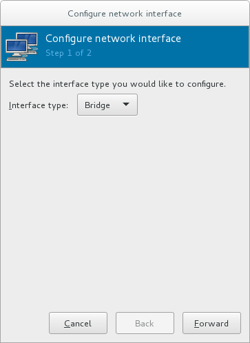
Figure 6.1. Adding a bridge
- In the field, enter a name for the bridge, such as br0.
- Select a from the drop-down menu. Choose from one of the following:
- none - deactivates the bridge
- onboot - activates the bridge on the next guest virtual machine reboot
- hotplug - activates the bridge even if the guest virtual machine is running
- Check the check box to activate the bridge immediately.
- To configure either the or , click the appropriate button. A separate window will open to specify the required settings. Make any necessary changes and click when done.
- Select the physical interface to connect to your virtual machines. If the interface is currently in use by another guest virtual machine, you will receive a warning message.
- Click and the wizard closes, taking you back to the menu.

Figure 6.2. Adding a bridge
6.4.3. Bridged Networking with libvirt
Important
macTableManager attribute of a network's <bridge> element to 'libvirt' in the host's XML configuration file:
<bridge name='br0' macTableManager='libvirt'/>This will turn off learning (flood) mode on all bridge ports, and libvirt will add or remove entries to the FDB as necessary. Along with removing the overhead of learning the proper forwarding ports for MAC addresses, this also allows the kernel to disable promiscuous mode on the physical device that connects the bridge to the network, which further reduces overhead.
Chapter 7. Overcommitting with KVM
7.1. Introduction
7.2. Overcommitting Memory
Important
Important
7.3. Overcommitting Virtualized CPUs
Important
Chapter 8. KVM Guest Timing Management
- Interrupts cannot always be delivered simultaneously and instantaneously to all guest virtual machines. This is because interrupts in virtual machines are not true interrupts. Instead, they are injected into the guest virtual machine by the host machine.
- The host may be running another guest virtual machine, or a different process. Therefore, the precise timing typically required by interrupts may not always be possible.
Important
ntpd service. For more information, see the Red Hat Enterprise 6 Deployment Guide.
ntpd or by the chronyd service. Note that Chrony has some advantages on virtual machines. For more information, see the Configuring NTP Using the chrony Suite and Configuring NTP Using ntpd sections in the Red Hat Enterprise Linux 7 System Administrator's Guide.
By default, the guest synchronizes its time with the hypervisor as follows:
- When the guest system boots, the guest reads the time from the emulated Real Time Clock (RTC).
- When the NTP protocol is initiated, it automatically synchronizes the guest clock. Afterwards, during normal guest operation, NTP performs clock adjustments in the guest.
- When a guest is resumed after a pause or a restoration process, a command to synchronize the guest clock to a specified value should be issued by the management software (such as virt-manager). This synchronization works only if the QEMU guest agent is installed in the guest and supports the feature. The value to which the guest clock synchronizes is usually the host clock value.
Modern Intel and AMD CPUs provide a constant Time Stamp Counter (TSC). The count frequency of the constant TSC does not vary when the CPU core itself changes frequency, for example to comply with a power-saving policy. A CPU with a constant TSC frequency is necessary in order to use the TSC as a clock source for KVM guests.
constant_tsc flag is present. To determine if your CPU has the constant_tsc flag enter the following command:
$ cat /proc/cpuinfo | grep constant_tscconstant_tsc bit. If no output is given, follow the instructions below.
Systems without a constant TSC frequency cannot use the TSC as a clock source for virtual machines, and require additional configuration. Power management features interfere with accurate time keeping and must be disabled for guest virtual machines to accurately keep time with KVM.
Important
constant_tsc bit, disable all power management features . Each system has several timers it uses to keep time. The TSC is not stable on the host, which is sometimes caused by cpufreq changes, deep C state, or migration to a host with a faster TSC. Deep C sleep states can stop the TSC. To prevent the kernel using deep C states append processor.max_cstate=1 to the kernel boot. To make this change persistent, edit values of the GRUB_CMDLINE_LINUX key in the /etc/default/grubfile. For example. if you want to enable emergency mode for each boot, edit the entry as follows:
GRUB_CMDLINE_LINUX="emergency"
cpufreq (only necessary on hosts without the constant_tsc), install kernel-tools and enable the cpupower.service (systemctl enable cpupower.service). If you want to disable this service every time the guest virtual machine boots, change the configuration file in /etc/sysconfig/cpupower and change the CPUPOWER_START_OPTS and CPUPOWER_STOP_OPTS. Valid limits can be found in the /sys/devices/system/cpu/cpuid/cpufreq/scaling_available_governors files. For more information on this package or on power management and governors, see the Red Hat Enterprise Linux 7 Power Management Guide.
8.1. Host-wide Time Synchronization
Important
- Set the
ptp_kvmmodule to load after reboot.#
echo ptp_kvm > /etc/modules-load.d/ptp_kvm.conf - Add the
/dev/ptp0clock as a reference to the chrony configuration:#
echo "refclock PHC /dev/ptp0 poll 2" >> /etc/chrony.conf - Restart the chrony daemon:
#
systemctl restart chronyd - To verify the host-guest time synchronization has been configured correctly, use the
chronyc sourcescommand on a guest. The output should look similar to the following:#
chronyc sources210 Number of sources = 1 MS Name/IP address Stratum Poll Reach LastRx Last sample =============================================================================== #* PHC0 0 2 377 4 -6ns[ -6ns] +/- 726ns
8.2. Required Time Management Parameters for Red Hat Enterprise Linux Guests
/kernel line in the /etc/grub2.cfg file of the guest virtual machine.
Note
Table 8.1. Kernel parameter requirements
| Red Hat Enterprise Linux version | Additional guest kernel parameters |
|---|---|
| 7.0 and later on AMD64 and Intel 64 systems with kvm-clock | Additional parameters are not required |
| 6.1 and later on AMD64 and Intel 64 systems with kvm-clock | Additional parameters are not required |
| 6.0 on AMD64 and Intel 64 systems with kvm-clock | Additional parameters are not required |
| 6.0 on AMD64 and Intel 64 systems without kvm-clock | notsc lpj=n |
Note
lpj parameter requires a numeric value equal to the loops per jiffy value of the specific CPU on which the guest virtual machine runs. If you do not know this value, do not set the lpj parameter.
8.3. Steal Time Accounting
/proc/stat. It is automatically reported by utilities such as top and vmstat. It is displayed as "%st", or in the "st" column. Note that it cannot be switched off.
Chapter 9. Network Booting with libvirt
Warning
9.1. Preparing the Boot Server
- A PXE Server (DHCP and TFTP) - This can be a libvirt internal server, manually-configured dhcpd and tftpd, dnsmasq, a server configured by Cobbler, or some other server.
- Boot images - for example, PXELINUX configured manually or by Cobbler.
9.1.1. Setting up a PXE Boot Server on a Private libvirt Network
Procedure 9.1. Configuring the PXE boot server
- Place the PXE boot images and configuration in
/var/lib/tftpboot. - enter the following commands:
#
virsh net-destroy default#virsh net-edit default - Edit the
<ip>element in the configuration file for the default network to include the appropriate address, network mask, DHCP address range, and boot file, where BOOT_FILENAME represents the file name you are using to boot the guest virtual machine.<ip address='192.168.122.1' netmask='255.255.255.0'> <tftp root='/var/lib/tftpboot' /> <dhcp> <range start='192.168.122.2' end='192.168.122.254' /> <bootp file='BOOT_FILENAME' /> </dhcp> </ip> - Run:
#
virsh net-start default - Boot the guest using PXE (refer to Section 9.2, “Booting a Guest Using PXE”).
9.2. Booting a Guest Using PXE
9.2.1. Using bridged networking
Procedure 9.2. Booting a guest using PXE and bridged networking
- Ensure bridging is enabled such that the PXE boot server is available on the network.
- Boot a guest virtual machine with PXE booting enabled. You can use the
virt-installcommand to create a new virtual machine with PXE booting enabled, as shown in the following example command:virt-install --pxe --network bridge=breth0 --prompt
Alternatively, ensure that the guest network is configured to use your bridged network, and that the XML guest configuration file has a<boot dev='network'/>element inside the<os>element, as shown in the following example:<os> <type arch='x86_64' machine='pc-i440fx-rhel7.0.0'>hvm</type> <boot dev='network'/> <boot dev='hd'/> </os> <interface type='bridge'> <mac address='52:54:00:5a:ad:cb'/> <source bridge='breth0'/> <target dev='vnet0'/> <alias name='net0'/> <address type='pci' domain='0x0000' bus='0x00' slot='0x03' function='0x0'/> </interface>
9.2.2. Using a Private libvirt Network
Procedure 9.3. Using a private libvirt network
- Configure PXE booting on libvirt as shown in Section 9.1.1, “Setting up a PXE Boot Server on a Private libvirt Network”.
- Boot a guest virtual machine using libvirt with PXE booting enabled. You can use the
virt-installcommand to create/install a new virtual machine using PXE:virt-install --pxe --network network=default --prompt
<boot dev='network'/> element inside the <os> element, as shown in the following example:
<os> <type arch='x86_64' machine='pc-i440fx-rhel7.0.0'>hvm</type> <boot dev='network'/> <boot dev='hd'/> </os>
<interface type='network'> <mac address='52:54:00:66:79:14'/> <source network='default'/> <target dev='vnet0'/> <alias name='net0'/> <address type='pci' domain='0x0000' bus='0x00' slot='0x03' function='0x0'/> </interface>
Chapter 10. Registering the Hypervisor and Virtual Machine
- Subscriptions specific to virtual systems are readily available and can be applied to all of the associated guest VMs.
- All subscription benefits that can be inherited from the hypervisor are readily available and can be applied to all of the associated guest VMs.
Note
10.1. Installing virt-who on the Host Physical Machine
Register the KVM hypervisor
Register the KVM Hypervisor by running thesubscription-manager register [options]command in a terminal as the root user on the host physical machine. More options are available using the #subscription-manager register --helpmenu. In cases where you are using a user name and password, use the credentials that are known to the Subscription Manager application. If this is your very first time subscribing and you do not have a user account, contact customer support. For example to register the VM as 'admin' with 'secret' as a password, you would send the following command:[root@rhel-server ~]#
subscription-manager register --username=admin --password=secret --auto-attachInstall the virt-who packages
Install the virt-who packages, by running the following command on the host physical machine:#
yum install virt-whoCreate a virt-who configuration file
For each hypervisor, add a configuration file in the/etc/virt-who.d/directory. At a minimum, the file must contain the following snippet:[libvirt] type=libvirt
For more detailed information on configuringvirt-who, see Section 10.1.1, “Configuringvirt-who”.Start the virt-who service
Start the virt-who service by running the following command on the host physical machine:#
systemctl start virt-who.service#systemctl enable virt-who.serviceConfirm virt-who service is receiving guest information
At this point, the virt-who service will start collecting a list of domains from the host. Check the/var/log/rhsm/rhsm.logfile on the host physical machine to confirm that the file contains a list of the guest VMs. For example:2015-05-28 12:33:31,424 DEBUG: Libvirt domains found: [{'guestId': '58d59128-cfbb-4f2c-93de-230307db2ce0', 'attributes': {'active': 0, 'virtWhoType': 'libvirt', 'hypervisorType': 'QEMU'}, 'state': 5}]
Procedure 10.1. Managing the subscription on the customer portal
Subscribing the hypervisor
As the virtual machines will be receiving the same subscription benefits as the hypervisor, it is important that the hypervisor has a valid subscription and that the subscription is available for the VMs to use.Log in to the Customer Portal
Provide your Red Hat account credentials at the Red Hat Customer Portal to log in.Click the Systems link
Go to the Systems section of the My Subscriptions interface.Select the hypervisor
On the Systems page, there is a table of all subscribed systems. Click the name of the hypervisor (for examplelocalhost.localdomain). In the details page that opens, click Attach a subscription and select all the subscriptions listed. Click . This will attach the host's physical subscription to the hypervisor so that the guests can benefit from the subscription.
Subscribing the guest virtual machines - first time use
This step is for those who have a new subscription and have never subscribed a guest virtual machine before. If you are adding virtual machines, skip this step. To consume the subscription assigned to the hypervisor profile on the machine running the virt-who service, auto subscribe by running the following command in a terminal on the guest virtual machine.[root@virt-who ~]#
subscription-manager attach --autoSubscribing additional guest virtual machines
If you just subscribed a virtual machine for the first time, skip this step. If you are adding additional virtual machines, note that running this command will not necessarily re-attach the same subscriptions to the guest virtual machine. This is because removing all subscriptions then allowing auto-attach to resolve what is necessary for a given guest virtual machine may result in different subscriptions consumed than before. This may not have any effect on your system, but it is something you should be aware about. If you used a manual attachment procedure to attach the virtual machine, which is not described below, you will need to re-attach those virtual machines manually as the auto-attach will not work. Use the following command to first remove the subscriptions for the old guests, and then use the auto-attach to attach subscriptions to all the guests. Run these commands on the guest virtual machine.[root@virt-who ~]#
subscription-manager remove --all[root@virt-who ~]#subscription-manager attach --autoConfirm subscriptions are attached
Confirm that the subscription is attached to the hypervisor by running the following command on the guest virtual machine:[root@virt-who ~]#
subscription-manager list --consumedOutput similar to the following will be displayed. Pay attention to the Subscription Details. It should say 'Subscription is current'.[root@virt-who ~]#
subscription-manager+-------------------------------------------+ Consumed Subscriptions +-------------------------------------------+ Subscription Name: Awesome OS with unlimited virtual guests Provides: Awesome OS Server Bits SKU: awesomeos-virt-unlimited Contract: 0 Account: ######### Your account number ##### Serial: ######### Your serial number ###### Pool ID: XYZ123list --consumed Provides Management: No
Active: True
Quantity Used: 1
Service Level:
Service Type:
Status Details: Subscription is current
Provides Management: No
Active: True
Quantity Used: 1
Service Level:
Service Type:
Status Details: Subscription is current  Subscription Type:
Starts: 01/01/2015
Ends: 12/31/2015
System Type: Virtual
The ID for the subscription to attach to the system is displayed here. You will need this ID if you need to attach the subscription manually.Indicates if your subscription is current. If your subscription is not current, an error message appears. One example is Guest has not been reported on any host and is using a temporary unmapped guest subscription. In this case the guest needs to be subscribed. In other cases, use the information as indicated in Section 10.5.2, “I have subscription status errors, what do I do?”.
Subscription Type:
Starts: 01/01/2015
Ends: 12/31/2015
System Type: Virtual
The ID for the subscription to attach to the system is displayed here. You will need this ID if you need to attach the subscription manually.Indicates if your subscription is current. If your subscription is not current, an error message appears. One example is Guest has not been reported on any host and is using a temporary unmapped guest subscription. In this case the guest needs to be subscribed. In other cases, use the information as indicated in Section 10.5.2, “I have subscription status errors, what do I do?”.Register additional guests
When you install new guest VMs on the hypervisor, you must register the new VM and use the subscription attached to the hypervisor, by running the following commands on the guest virtual machine:#
subscription-manager register#subscription-manager attach --auto#subscription-manager list --consumed
10.1.1. Configuring virt-who
virt-who service is configured using the following files:
/etc/virt-who.conf- Contains general configuration information including the interval for checking connected hypervisors for changes./etc/virt-who.d/hypervisor_name.conf- Contains configuration information for a specific hypervisor.
virt-who.conf. To run the wizard, browse to Red Hat Virtualization Agent (virt-who) Configuration Helper on the Customer Portal.
- :
Subscription Asset Manager - :
libvirt
virt-who will automatically provide the selected subscriptions to existing and future guests on the specified hypervisor.
virt-who-config man page.
10.2. Registering a New Guest Virtual Machine
[root@virt-server ~]# subscription-manager register --username=admin --password=secret --auto-attach10.3. Removing a Guest Virtual Machine Entry
[root@virt-guest ~]# subscription-manager unregisterLogin to the Subscription Manager
The Subscription Manager is located on the Red Hat Customer Portal. Login to the Customer Portal using your user name and password, by clicking the login icon at the top of the screen.Click the Subscriptions tab
Click the Subscriptions tab.Click the Systems link
Scroll down the page and click the Systems link.Delete the system
To delete the system profile, locate the specified system's profile in the table, select the check box beside its name and click .
10.4. Installing virt-who Manually
Procedure 10.2. How to attach a subscription manually
List subscription information and find the Pool ID
First you need to list the available subscriptions which are of the virtual type. Enter the following command:[root@server1 ~]#
subscription-manager listSubscription Name: Red Hat Enterprise Linux ES (Basic for Virtualization) Provides: Red Hat Beta Oracle Java (for RHEL Server) Red Hat Enterprise Linux Server SKU: ------- Pool ID: XYZ123 Available: 40 Suggested: 1 Service Level: Basic Service Type: L1-L3 Multi-Entitlement: No Ends: 01/02/2017 System Type: Virtual--avail --match-installed | grep 'Virtual' -B12Note the Pool ID displayed. Copy this ID as you will need it in the next step.Attach the subscription with the Pool ID
Using the Pool ID you copied in the previous step run the attach command. Replace the Pool ID XYZ123 with the Pool ID you retrieved. Enter the following command:[root@server1 ~]#
subscription-manager attachSuccessfully attached a subscription for: Red Hat Enterprise Linux ES (Basic for Virtualization)--pool=XYZ123
10.5. Troubleshooting virt-who
10.5.1. Why is the hypervisor status red?
10.5.2. I have subscription status errors, what do I do?
- System not properly subscribed
- Status unknown
- Late binding of a guest to a hypervisor through virt-who (host/guest mapping)
rhsm.log, located in the /var/log/rhsm/ directory.
Chapter 11. Enhancing Virtualization with the QEMU Guest Agent and SPICE Agent
Note
11.1. QEMU Guest Agent
Important
11.1.1. Setting up Communication between the QEMU Guest Agent and Host
Note
11.1.1.1. Configuring the QEMU Guest Agent on a Linux Guest
virsh or virt-manager can be used to configure communication between the guest and the QEMU guest agent. The following instructions describe how to configure the QEMU guest agent on a Linux guest.
Procedure 11.1. Setting up communication between guest agent and host with virsh on a shut down Linux guest
Shut down the virtual machine
Ensure the virtual machine (named rhel7 in this example) is shut down before configuring the QEMU guest agent:#
virsh shutdown rhel7Add the QEMU guest agent channel to the guest XML configuration
Edit the guest's XML file to add the QEMU guest agent details:#
virsh edit rhel7Add the following to the guest's XML file and save the changes:<channel type='unix'> <target type='virtio' name='org.qemu.guest_agent.0'/> </channel>
Start the virtual machine
#
virsh start rhel7Install the QEMU guest agent on the guest
Install the QEMU guest agent if not yet installed in the guest virtual machine:#
yum install qemu-guest-agentStart the QEMU guest agent in the guest
Start the QEMU guest agent service in the guest:#
systemctl start qemu-guest-agent
Procedure 11.2. Setting up communication between guest agent and host on a running Linux guest
Create an XML file for the QEMU guest agent
#
cat agent.xml<channel type='unix'> <target type='virtio' name='org.qemu.guest_agent.0'/> </channel>Attach the QEMU guest agent to the virtual machine
Attach the QEMU guest agent to the running virtual machine (named rhel7 in this example) with this command:#
virsh attach-device rhel7 agent.xmlInstall the QEMU guest agent on the guest
Install the QEMU guest agent if not yet installed in the guest virtual machine:#
yum install qemu-guest-agentStart the QEMU guest agent in the guest
Start the QEMU guest agent service in the guest:#
systemctl start qemu-guest-agent
Procedure 11.3. Setting up communication between the QEMU guest agent and host with virt-manager
Shut down the virtual machine
Ensure the virtual machine is shut down before configuring the QEMU guest agent.To shut down the virtual machine, select it from the list of virtual machines in Virtual Machine Manager, then click the light switch icon from the menu bar.Add the QEMU guest agent channel to the guest
Open the virtual machine's hardware details by clicking the lightbulb icon at the top of the guest window.Click the button to open the Add New Virtual Hardware window, and select Channel.Select the QEMU guest agent from the Name drop-down list and click :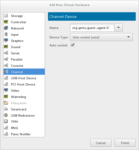
Figure 11.1. Selecting the QEMU guest agent channel device
Start the virtual machine
To start the virtual machine, select it from the list of virtual machines in Virtual Machine Manager, then click on the menu bar.
Install the QEMU guest agent on the guest
Open the guest with virt-manager and install the QEMU guest agent if not yet installed in the guest virtual machine:#
yum install qemu-guest-agentStart the QEMU guest agent in the guest
Start the QEMU guest agent service in the guest:#
systemctl start qemu-guest-agent
11.2. Using the QEMU Guest Agent with libvirt
virsh commands:
virsh shutdown --mode=agent- This shutdown method is more reliable thanvirsh shutdown --mode=acpi, asvirsh shutdownused with the QEMU guest agent is guaranteed to shut down a cooperative guest in a clean state. If the agent is not present, libvirt must instead rely on injecting an ACPI shutdown event, but some guests ignore that event and thus will not shut down.Can be used with the same syntax forvirsh reboot.virsh snapshot-create --quiesce- Allows the guest to flush its I/O into a stable state before the snapshot is created, which allows use of the snapshot without having to perform a fsck or losing partial database transactions. The guest agent allows a high level of disk contents stability by providing guest co-operation.virsh domfsfreezeandvirsh domfsthaw- Quiesces the guest filesystem in isolation.virsh domfstrim- Instructs the guest to trim its filesystem.virsh domtime- Queries or sets the guest's clock.virsh setvcpus --guest- Instructs the guest to take CPUs offline.virsh domifaddr --source agent- Queries the guest operating system's IP address via the guest agent.virsh domfsinfo- Shows a list of mounted filesystems within the running guest.virsh set-user-password- Sets the password for a user account in the guest.
11.2.1. Creating a Guest Disk Backup
- File system applications / databases flush working buffers to the virtual disk and stop accepting client connections
- Applications bring their data files into a consistent state
- Main hook script returns
- qemu-guest-agent freezes the filesystems and the management stack takes a snapshot
- Snapshot is confirmed
- Filesystem function resumes
virsh snapshot-create --quiesce --disk-only command (alternatively, run virsh snapshot-create-as guest_name --quiesce --disk-only, explained in further detail in Section 20.39.2, “Creating a Snapshot for the Current Guest Virtual Machine”).
Note
restorecon -FvvR command listed in Table 11.1, “QEMU guest agent package contents” in the table row labeled /etc/qemu-ga/fsfreeze-hook.d/.
Table 11.1. QEMU guest agent package contents
| File name | Description |
|---|---|
/usr/lib/systemd/system/qemu-guest-agent.service | Service control script (start/stop) for the QEMU guest agent. |
/etc/sysconfig/qemu-ga | Configuration file for the QEMU guest agent, as it is read by the /usr/lib/systemd/system/qemu-guest-agent.service control script. The settings are documented in the file with shell script comments. |
/usr/bin/qemu-ga | QEMU guest agent binary file. |
/etc/qemu-ga | Root directory for hook scripts. |
/etc/qemu-ga/fsfreeze-hook | Main hook script. No modifications are needed here. |
/etc/qemu-ga/fsfreeze-hook.d | Directory for individual, application-specific hook scripts. The guest system administrator should copy hook scripts manually into this directory, ensure proper file mode bits for them, and then run restorecon -FvvR on this directory. |
/usr/share/qemu-kvm/qemu-ga/ | Directory with sample scripts (for example purposes only). The scripts contained here are not executed. |
/etc/qemu-ga/fsfreeze-hook logs its own messages, as well as the application-specific script's standard output and error messages, in the following log file: /var/log/qemu-ga/fsfreeze-hook.log. For more information, see the libvirt upstream website.
11.3. SPICE Agent
11.3.1. Setting up Communication between the SPICE Agent and Host
virsh or virt-manager can be used to configure communication between the guest and the SPICE agent. The following instructions describe how to configure the SPICE agent on a Linux guest.
Procedure 11.4. Setting up communication between guest agent and host with virsh on a Linux guest
Shut down the virtual machine
Ensure the virtual machine (named rhel7 in this example) is shut down before configuring the SPICE agent:#
virsh shutdown rhel7Add the SPICE agent channel to the guest XML configuration
Edit the guest's XML file to add the SPICE agent details:#
virsh edit rhel7Add the following to the guest's XML file and save the changes:<channel type='spicevmc'> <target type='virtio' name='com.redhat.spice.0'/> </channel>
Start the virtual machine
#
virsh start rhel7Install the SPICE agent on the guest
Install the SPICE agent if not yet installed in the guest virtual machine:#
yum install spice-vdagentStart the SPICE agent in the guest
Start the SPICE agent service in the guest:#
systemctl start spice-vdagent
Procedure 11.5. Setting up communication between SPICE agent and host on a running Linux guest
Create an XML file for the SPICE agent
#
cat agent.xml<channel type='spicevmc'> <target type='virtio' name='com.redhat.spice.0'/> </channel>Attach the SPICE agent to the virtual machine
Attach the SPICE agent to the running virtual machine (named rhel7 in this example) with this command:#
virsh attach-device rhel7 agent.xmlInstall the SPICE agent on the guest
Install the SPICE agent if not yet installed in the guest virtual machine:#
yum install spice-vdagentStart the SPICE agent in the guest
Start the SPICE agent service in the guest:#
systemctl start spice-vdagent
Procedure 11.6. Setting up communication between the SPICE agent and host with virt-manager
Shut down the virtual machine
Ensure the virtual machine is shut down before configuring the SPICE agent.To shut down the virtual machine, select it from the list of virtual machines in Virtual Machine Manager, then click the light switch icon from the menu bar.Add the SPICE agent channel to the guest
Open the virtual machine's hardware details by clicking the lightbulb icon at the top of the guest window.Click the button to open the Add New Virtual Hardware window, and select Channel.Select the SPICE agent from the Name drop-down list, edit the channel address, and click :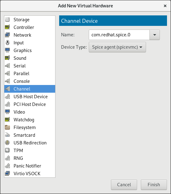
Figure 11.2. Selecting the SPICE agent channel device
Start the virtual machine
To start the virtual machine, select it from the list of virtual machines in Virtual Machine Manager, then click
on the menu bar.
Install the SPICE agent on the guest
Open the guest with virt-manager and install the SPICE agent if not yet installed in the guest virtual machine:#
yum install spice-vdagentStart the SPICE agent in the guest
Start the SPICE agent service in the guest:#
systemctl start spice-vdagent
Chapter 12. Nested Virtualization
12.1. Overview
12.2. Setup
- Enable: The feature is disabled by default. To enable it, use the following procedure on the L0 host physical machine.For Intel:
- Check whether nested virtualization is available on your host system.
$
cat /sys/module/kvm_intel/parameters/nestedIf this command returnsYor1, the feature is enabled.If the command returns0orN, use steps ii and iii. - Unload the
kvm_intelmodule:#
modprobe -r kvm_intel - Activate the nesting feature:
#
modprobe kvm_intel nested=1 - The nesting feature is now enabled only until the next reboot of the L0 host. To enable it permanently, add the following line to the
/etc/modprobe.d/kvm.conffile:options kvm_intel nested=1
For AMD:- Check whether nested virtualization is available on your system:
$
cat /sys/module/kvm_amd/parameters/nestedIf this command returnsYor1, the feature is enabled.If the command returns0orN, use steps ii and iii. - Unload the
kvm_amdmodule#
modprobe -r kvm_amd - Activate the nesting feature
#
modprobe kvm_amd nested=1 - The nesting feature is now enabled only until the next reboot of the L0 host. To enable it permanently, add the following line to the
/etc/modprobe.d/kvm.conffile:options kvm_amd nested=1
- Configure your L1 virtual machine for nested virtualization using one of the following methods:
- virt-manager
- Open the GUI of the intended guest and click the Show Virtual Hardware Details icon.
- Select the Processor menu, and in the Configuration section, type
host-passthroughin the Model field (do not use the drop-down selection), and click Apply.
- Domain XML
- Add the following line to the domain XML file of the guest:
<cpu mode='host-passthrough'/>
If the guest's XML configuration file already contains a<cpu>element, rewrite it.
- To start using nested virtualization, install an L2 guest within the L1 guest. To do this, follow the same procedure as when installing the L1 guest - see Chapter 3, Creating a Virtual Machine for more information.
12.3. Restrictions and Limitations
- It is strongly recommended to run Red Hat Enterprise Linux 7.2 or later in the L0 host and the L1 guests. L2 guests can contain any guest system supported by Red Hat.
- It is not supported to migrate L1 or L2 guests.
- Use of L2 guests as hypervisors and creating L3 guests is not supported.
- Not all features available on the host are available to be utilized by the L1 hypervisor. For instance, IOMMU/VT-d or APICv cannot be used by the L1 hypervisor.
- To use nested virtualization, the host CPU must have the necessary feature flags. To determine if the L0 and L1 hypervisors are set up correctly, use the
cat /proc/cpuinfocommand on both L0 and L1, and make sure that the following flags are listed for the respective CPUs on both hypervisors:- For Intel - vmx (Hardware Virtualization) and ept (Extended Page Tables)
- For AMD - svm (equivalent to vmx) and npt (equivalent to ept)
Part II. Administration
qemu-img, virt-manager, and virsh tools.
Chapter 13. Managing Storage for Virtual Machines
13.1. Storage Concepts
Note
Note
mount -t nfs nfs.example.com:/path/to/share /path/to/data. A storage administrator responsible could define an NFS Storage Pool on the virtualization host to describe the exported server path and the client target path. This will allow libvirt to perform the mount either automatically when libvirt is started or as needed while libvirt is running. Files with the NFS Server exported directory are listed as storage volumes within the NFS storage pool.
mount nfs.example.com:/path/to/share /vmdata. If the storage pool is configured to autostart, libvirt ensures that the NFS shared disk is mounted on the directory specified when libvirt is started.
man virsh.
Procedure 13.1. Creating and Assigning Storage
Create storage pools
Create one or more storage pools from available storage media. For more information, see Section 13.2, “Using Storage Pools”.Create storage volumes
Create one or more storage volumes from the available storage pools. For more information, see Section 13.3, “Using Storage Volumes”.Assign storage devices to a virtual machine.
Assign one or more storage devices abstracted from storage volumes to a guest virtual machine. For more information, see Section 13.3.6, “Adding Storage Devices to Guests”.
13.2. Using Storage Pools
virsh commands and the Virtual Machine Manager.
13.2.1. Storage Pool Concepts
- Local storage pools
- Local storage pools are attached directly to the host server. They include local directories, directly attached disks, physical partitions, and Logical Volume Management (LVM) volume groups on local devices. Local storage pools are useful for development, testing, and small deployments that do not require migration or large numbers of virtual machines. Local storage pools may not be suitable for many production environments, because they cannot be used for live migration.
- Networked (shared) storage pools
- Networked storage pools include storage devices shared over a network using standard protocols. Networked storage is required when migrating virtual machines between hosts with virt-manager, but is optional when migrating with
virsh.For more information on migrating virtual machines, see Chapter 15, KVM Migration.
- Directory-based storage pools
- Disk-based storage pools
- Partition-based storage pools
- GlusterFS storage pools
- iSCSI-based storage pools
- LVM-based storage pools
- NFS-based storage pools
- vHBA-based storage pools with SCSI devices
libvirt storage pool types that are not supported by Red Hat Enterprise Linux:
- Multipath-based storage pool
- RBD-based storage pool
- Sheepdog-based storage pool
- Vstorage-based storage pool
- ZFS-based storage pool
Note
13.2.2. Creating Storage Pools
virsh and the Virtual Machine Manager. Using virsh enables you to specify all parameters, whereas using Virtual Machine Manager provides a graphic method for creating simpler storage pools.
13.2.2.1. Creating Storage Pools with virsh
Note
Procedure 13.2. Creating Storage Pools with virsh
Read recommendations and ensure that all prerequisites are met
For some storage pools, this guide recommends that you follow certain practices. In addition, there are prerequisites for some types of storage pools. To see the recommendations and prerequisites, if any, see Section 13.2.3, “Storage Pool Specifics”.Define the storage pool
Storage pools can be persistent or transient. A persistent storage pool survives a system restart of the host machine. A transient storage pool only exists until the host reboots.Do one of the following:- Define the storage pool using an XML file.a. Create a temporary XML file containing the storage pool information required for the new device.The XML file must contain specific fields, based on the storage pool type. For more information, see Section 13.2.3, “Storage Pool Specifics”.The following shows an example a storage pool definition XML file. In this example, the file is saved to
~/guest_images.xml<pool type='fs'> <name>guest_images_fs</name> <source> <device path='/dev/sdc1'/> </source> <target> <path>/guest_images</path> </target> </pool>b. Use thevirsh pool-definecommand to create a persistent storage pool or thevirsh pool-createcommand to create and start a transient storage pool.#
virsh pool-define ~/guest_images.xmlPool defined from guest_images_fsor#
virsh pool-create ~/guest_images.xmlPool created from guest_images_fsc. Delete the XML file created in step a. - Use the
virsh pool-define-ascommand to create a persistent storage pool or thevirsh pool-create-ascommand to create a transient storage pool.The following examples create a persistent and then a transient filesystem-based storage pool mapped to/dev/sdc1from the/guest_imagesdirectory.#
virsh pool-define-as guest_images_fs fs - - /dev/sdc1 - "/guest_images"Pool guest_images_fs definedor#
virsh pool-create-as guest_images_fs fs - - /dev/sdc1 - "/guest_images"Pool guest_images_fs createdNote
When using thevirshinterface, option names in the commands are optional. If option names are not used, use dashes for fields that do not need to be specified.
Verify that the pool was created
List all existing storage pools using thevirsh pool-list --all.#
virsh pool-list --allName State Autostart ----------------------------------------- default active yes guest_images_fs inactive noDefine the storage pool target path
Use thevirsh pool-buildcommand to create a storage pool target path for a pre-formatted file system storage pool, initialize the storage source device, and define the format of the data. Then use thevirsh pool-listcommand to ensure that the storage pool is listed.#
virsh pool-build guest_images_fsPool guest_images_fs built #ls -la /guest_imagestotal 8 drwx------. 2 root root 4096 May 31 19:38 . dr-xr-xr-x. 25 root root 4096 May 31 19:38 .. #virsh pool-list --allName State Autostart ----------------------------------------- default active yes guest_images_fs inactive noNote
Building the target path is only necessary for disk-based, file system-based, and logical storage pools. If libvirt detects that the source storage device's data format differs from the selected storage pool type, the build fails, unless theoverwriteoption is specified.Start the storage pool
Use thevirsh pool-startcommand to prepare the source device for usage.The action taken depends on the storage pool type. For example, for a file system-based storage pool, thevirsh pool-startcommand mounts the file system. For an LVM-based storage pool, thevirsh pool-startcommand activates the volume group usng thevgchangecommand.Then use thevirsh pool-list commandto ensure that the storage pool is active.#
virsh pool-start guest_images_fsPool guest_images_fs started #virsh pool-list --allName State Autostart ----------------------------------------- default active yes guest_images_fs active noNote
Thevirsh pool-startcommand is only necessary for persistent storage pools. Transient storage pools are automatically started when they are created.Turn on autostart (optional)
By default, a storage pool defined withvirshis not set to automatically start each timelibvirtdstarts. You can configure the storage pool to start automatically using thevirsh pool-autostartcommand.#
virsh pool-autostart guest_images_fsPool guest_images_fs marked as autostarted #virsh pool-list --allName State Autostart ----------------------------------------- default active yes guest_images_fs active yesThe storage pool is now automatically started each timelibvirtdstarts.Verify the storage pool
Verify that the storage pool was created correctly, the sizes reported are as expected, and the state is reported asrunning. Verify there is a "lost+found" directory in the target path on the file system, indicating that the device is mounted.#
virsh pool-info guest_images_fsName: guest_images_fs UUID: c7466869-e82a-a66c-2187-dc9d6f0877d0 State: running Persistent: yes Autostart: yes Capacity: 458.39 GB Allocation: 197.91 MB Available: 458.20 GB #mount | grep /guest_images/dev/sdc1 on /guest_images type ext4 (rw) #ls -la /guest_imagestotal 24 drwxr-xr-x. 3 root root 4096 May 31 19:47 . dr-xr-xr-x. 25 root root 4096 May 31 19:38 .. drwx------. 2 root root 16384 May 31 14:18 lost+found
13.2.2.2. Creating storage pools with Virtual Machine Manager
Note
Procedure 13.3. Creating Storage Pools with Virtual Machine Manager
Prepare the medium on which the storage pool will be created
This will differ for different types of storage pools. For details, see Section 13.2.3, “Storage Pool Specifics”.In this example, you may need to relabel the disk with a GUID Partition Table.Open the storage settings
- In Virtual Machine Manager, select the host connection you want to configure.Open the Edit menu and select Connection Details.
- Click the Storage tab in the Connection Details window.
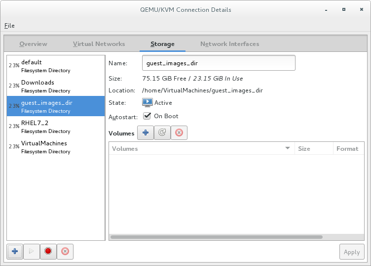
Figure 13.1. Storage tab
Create a new storage pool
Note
Using Virtual Machine Manager, you can only create persistent storage pools. Transient storage pools can only be created usingvirsh.Add a new storage pool (part 1)
Click the
button at the bottom of the window. The Add a New Storage Pool wizard appears.
Enter a for the storage pool. This example uses the name guest_images_fs.Select a storage pool type to create from the drop-down list. This example usesfs: Pre-Formatted Block Device.
Figure 13.2. Storage pool name and type
Click the button to continue.Add a new pool (part 2)
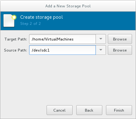
Figure 13.3. Storage pool path
Configure the storage pool with the relevant parameters. For information on the parameters for each type of storage pool, see Section 13.2.3, “Storage Pool Specifics”.For some types of storage pools, a Build Pool check box appears in the dialog. If you want to build the storage pool from the storage, check the Build Pool check box.Verify the details and click the button to create the storage pool.
13.2.3. Storage Pool Specifics
13.2.3.1. Directory-based storage pools
Parameters
virsh pool-define-as command, and the Virtual Machine Manager application, for creating a directory-based storage pool.
Table 13.1. Directory-based storage pool parameters
| Description | XML | pool-define-as | Virtual Machine Manager |
|---|---|---|---|
| The type of storage pool | <pool type='dir'> | [type] directory | dir: Filesystem Directory |
| The name of the storage pool | <name>name</name> | [name] name | Name |
| The path specifying the target. This will be the path used for the storage pool. |
<target> | target path_to_pool | Target Path |
virsh to create the storage pool, continue by verifying that the pool was created.
Examples
/guest_images directory:
<pool type='dir'>
<name>dirpool</name>
<target>
<path>/guest_images</path>
</target>
</pool> /guest_images directory:
# virsh pool-define-as dirpool dir --target "/guest_images"
Pool FS_directory defined/guest_images directory:

Figure 13.4. Add a new directory-based storage pool example
13.2.3.2. Disk-based storage pools
Recommendations
- Depending on the version of libvirt being used, dedicating a disk to a storage pool may reformat and erase all data currently stored on the disk device. It is strongly recommended that you back up the data on the storage device before creating a storage pool.
- Guests should not be given write access to whole disks or block devices (for example,
/dev/sdb). Use partitions (for example,/dev/sdb1) or LVM volumes.If you pass an entire block device to the guest, the guest will likely partition it or create its own LVM groups on it. This can cause the host physical machine to detect these partitions or LVM groups and cause errors.
Prerequisites
Note
virsh pool-build command.
# parted /dev/sdb
GNU Parted 2.1
Using /dev/sdb
Welcome to GNU Parted! Type 'help' to view a list of commands.
(parted) mklabel
New disk label type? gpt
(parted) quit
Information: You may need to update /etc/fstab.
#
Parameters
virsh pool-define-as command, and the Virtual Machine Manager application, for creating a disk-based storage pool.
Table 13.2. Disk-based storage pool parameters
| Description | XML | pool-define-as | Virtual Machine Manager |
|---|---|---|---|
| The type of storage pool | <pool type='disk'> | [type] disk | disk: Physical Disk Device |
| The name of the storage pool | <name>name</name> | [name] name | Name |
| The path specifying the storage device. For example, /dev/sdb |
<source> | source-dev path_to_disk | Source Path |
| The path specifying the target. This will be the path used for the storage pool. |
<target> | target path_to_pool | Target Path |
virsh to create the storage pool, continue with defining the storage pool.
Examples
<pool type='disk'>
<name>phy_disk</name>
<source>
<device path='/dev/sdb'/>
<format type='gpt'/>
</source>
<target>
<path>/dev</path>
</target>
</pool> # virsh pool-define-as phy_disk disk --source-format=gpt --source-dev=/dev/sdb --target /dev
Pool phy_disk defined
Figure 13.5. Add a new disk-based storage pool example
13.2.3.3. Filesystem-based storage pools
Recommendations
/dev/sdb). Guests should not be given write access to whole disks or block devices. This method should only be used to assign partitions (for example, /dev/sdb1) to storage pools.
Prerequisites
Note
virsh pool-build command.
# mkfs.ext4 /dev/sdc1Parameters
virsh pool-define-as command, and the Virtual Machine Manager application, for creating a filesystem-based storage pool from a partition.
Table 13.3. Filesystem-based storage pool parameters
| Description | XML | pool-define-as | Virtual Machine Manager |
|---|---|---|---|
| The type of storage pool | <pool type='fs'> | [type] fs | fs: Pre-Formatted Block Device |
| The name of the storage pool | <name>name</name> | [name] name | Name |
| The path specifying the partition. For example, /dev/sdc1 |
<source> | [source] path_to_partition | Source Path |
| The filesystem type, for example ext4 |
<format type='fs_type' /> | [source format] FS-format | N/A |
| The path specifying the target. This will be the path used for the storage pool. |
<target> | [target] path_to_pool | Target Path |
virsh to create the storage pool, continue with verifying that the storage pool was created.
Examples
<pool type='fs'>
<name>guest_images_fs</name>
<source>
<device path='/dev/sdc1'/>
<format type='auto'/>
</source>
<target>
<path>/guest_images</path>
</target>
</pool> # virsh pool-define-as guest_images_fs fs --source-dev /dev/sdc1 --target /guest_images
Pool guest_images_fs defined
Figure 13.6. Add a new filesystem-based storage pool example
13.2.3.4. GlusterFS-based storage pools
Recommendations
Prerequisites
Procedure 13.4. Preparing a Gluster server
- Obtain the IP address of the Gluster server by listing its status with the following command:
#
gluster volume statusStatus of volume: gluster-vol1 Gluster process Port Online Pid ------------------------------------------------------------------------------ Brick 222.111.222.111:/gluster-vol1 49155 Y 18634 Task Status of Volume gluster-vol1 ------------------------------------------------------------------------------ There are no active volume tasks - If not installed, install the glusterfs-fuse package.
- If not enabled, enable the virt_use_fusefs boolean. Check that it is enabled.
#
setsebool virt_use_fusefs on#getsebool virt_use_fusefsvirt_use_fusefs --> on
Parameters
virsh pool-define-as command, and the Virtual Machine Manager application, for creating a GlusterFS-based storage pool.
Table 13.4. GlusterFS-based storage pool parameters
| Description | XML | pool-define-as | Virtual Machine Manager |
|---|---|---|---|
| The type of storage pool | <pool type='gluster'> | [type] gluster | Gluster: Gluster Filesystem |
| The name of the storage pool | <name>name</name> | [name] name | Name |
| The hostname or IP address of the Gluster server |
<source> | source-host hostname | Host Name |
| The name of the Gluster server | <name='Gluster-name' /> | source-name Gluster-name | Source Name |
| The path on the Gluster server used for the storage pool |
<dir path='Gluster-path' /> | source-path Gluster-path | Source Path |
virsh to create the storage pool, continue with verifying that the storage pool was created.
Examples
<pool type='gluster'>
<name>Gluster_pool</name>
<source>
<host name='111.222.111.222'/>
<dir path='/'/>
<name>gluster-vol1</name>
</source>
</pool> # pool-define-as --name Gluster_pool --type gluster --source-host 111.222.111.222 --source-name gluster-vol1 --source-path /
Pool Gluster_pool defined
Figure 13.7. Add a new GlusterFS-based storage pool example
13.2.3.5. iSCSI-based storage pools
Recommendations
Prerequisites
Procedure 13.5. Creating an iSCSI target
Install the targetcli package
#
yum install targetcliLaunch the
targetclicommand set#
targetcliCreate storage objects
Create three storage objects, using a storage pool.- Create a block storage object
- Navigate to the
/backstores/blockdirectory. - Run the
createcommand.#
create [block-name][filepath]For example:#
create block1 dev=/dev/sdb1
- Create a fileio object
- Navigate to the
/fileiodirectory. - Run the
createcommand.#
create [fileio-name][image-name] [image-size]For example:#
create fileio1 /foo.img 50M
- Create a ramdisk object
- Navigate to the
/ramdiskdirectory. - Run the
createcommand.#
create [ramdisk-name] [ramdisk-size]For example:#
create ramdisk1 1M
- Make note of the names of the disks created in this step. They will be used later.
Create an iSCSI target
- Navigate to the
/iscsidirectory. - Create the target in one of two ways:
- Run the
createcommand with no parameters.The iSCSI qualified name (IQN) is generated automatically. - Run the
createcommand specifying the IQN and the server. For example:#
create iqn.2010-05.com.example.server1:iscsirhel7guest
Define the portal IP address
To export the block storage over iSCSI, the portal, LUNs, and access control lists ACLs must first be configured.The portal includes the IP address and TCP that the target monitors, and the initiators to which it connects. iSCSI uses port 3260. This port is configured by default.To connect to port 3260:- Navigate to the
/tpgdirectory. - Run the following:
#
portals/ createThis command makes all available IP addresses listening to port 3260.If you want only a single IP address to listen to port 3260, add the IP address to the end of the command. For example:#
portals/ create 143.22.16.33
Configure the LUNs and assign storage objects to the fabric
This step uses the storage objects created in creating storage objects.- Navigate to the
lunsdirectory for the TPG created in defining the portal IP address. For example:#
iscsi>iqn.iqn.2010-05.com.example.server1:iscsirhel7guest - Assign the first LUN to the ramdisk. For example:
#
create /backstores/ramdisk/ramdisk1 - Assign the second LUN to the block disk. For example:
#
create /backstores/block/block1 - Assign the third LUN to the fileio disk. For example:
#
create /backstores/fileio/fileio1 - List the resulting LUNs.
/iscsi/iqn.20...csirhel7guest
lso- tgp1 ............................................................[enabled, auth] o- acls...................................................................[0 ACL] o- luns..................................................................[3 LUNs] | o- lun0......................................................[ramdisk/ramdisk1] | o- lun1...............................................[block/block1 (dev/vdb1)] | o- lun2................................................[fileio/file1 (foo.img)] o- portals.............................................................[1 Portal] o- IP-ADDRESS:3260.........................................................[OK]
Create ACLs for each initiator
Enable authentication when the initiator connects. You can also resrict specified LUNs to specified intiators. Targets and initiators have unique names. iSCSI initiators use IQNs.- Find the IQN of the iSCSI initiator, using the initiator name. For example:
#
cat /etc/iscsi/initiator2.iscsiInitiatorName=create iqn.2010-05.com.example.server1:iscsirhel7guestThis IQN is used to create the ACLs. - Navigate to the
aclsdirectory. - Create ACLs by doing one of the following:
- Create ACLS for all LUNs and initiators by running the
createcommand with no parameters.#
create - Create an ACL for a specific LUN and initiator, run the
createcommand specifying the IQN of the iSCSI intiator. For example:#
create iqn.2010-05.com.example.server1:888 - Configure the kernel target to use a single user ID and password for all initiators.
#
set auth userid=user_ID#set auth password=password#set attribute authentication=1#set attribute generate_node_acls=1
After completing this procedure, continue by securing the storage pool.Save the configuration
Make the configuration persistent by overwriting the previous boot settings.#
saveconfigEnable the service
To apply the saved settings on the next boot, enable the service.#
systemctl enable target.service
Optional procedures
Procedure 13.6. Configuring a logical volume on a RAID array
Create a RAID5 array
For information on creating a RAID5 array, see the Red Hat Enterprise Linux 7 Storage Administration Guide.Create an LVM logical volume on the RAID5 array
For information on creating an LVM logical volume on a RAID5 array, see the Red Hat Enterprise Linux 7 Logical Volume Manager Administration Guide.
Procedure 13.7. Testing discoverability
Ensure that the new iSCSI device is discoverable.
#
iscsiadm --mode discovery --type sendtargets --portal server1.example.com143.22.16.33:3260,1 iqn.2010-05.com.example.server1:iscsirhel7guest
Procedure 13.8. Testing device attachment
Attach the new iSCSI device
Attach the new device (iqn.2010-05.com.example.server1:iscsirhel7guest) to determine whether the device can be attached.#
iscsiadm -d2 -m node --loginscsiadm: Max file limits 1024 1024 Logging in to [iface: default, target: iqn.2010-05.com.example.server1:iscsirhel7guest, portal: 143.22.16.33,3260] Login to [iface: default, target: iqn.2010-05.com.example.server1:iscsirhel7guest, portal: 143.22.16.33,3260] successful.Detach the device
#
iscsiadm -d2 -m node --logoutscsiadm: Max file limits 1024 1024 Logging out of session [sid: 2, target: iqn.2010-05.com.example.server1:iscsirhel7guest, portal: 143.22.16.33,3260 Logout of [sid: 2, target: iqn.2010-05.com.example.server1:iscsirhel7guest, portal: 143.22.16.33,3260] successful.
Procedure 13.9. Using libvirt secrets for an iSCSI storage pool
Note
virsh to secure an iSCSI storage pool. This can be configured before or after the pool is defined, but the pool must be started for the authentication settings to take effect.
Create a libvirt secret file
Create a libvirt secret file with a challenge-handshake authentication protocol (CHAP) user name. For example:<secret ephemeral='no' private='yes'> <description>Passphrase for the iSCSI example.com server</description> <usage type='iscsi'> <target>iscsirhel7secret</target> </usage> </secret>Define the secret
#
virsh secret-define secret.xmlVerify the UUID
#
virsh secret-listUUID Usage -------------------------------------------------------------------------------- 2d7891af-20be-4e5e-af83-190e8a922360 iscsi iscsirhel7secretAssign a secret to the UID
Use the following commands to assign a secret to the UUID in the output of the previous step. This ensures that the CHAP username and password are in a libvirt-controlled secret list.#
MYSECRET=`printf %s "password123" | base64`#virsh secret-set-value 2d7891af-20be-4e5e-af83-190e8a922360 $MYSECRETAdd an authentication entry to the storage pool
Modify the<source>entry in the storage pool's XML file usingvirsh edit, and add an<auth>element, specifyingauthentication type,username, andsecret usage.For example:<pool type='iscsi'> <name>iscsirhel7pool</name> <source> <host name='192.168.122.1'/> <device path='iqn.2010-05.com.example.server1:iscsirhel7guest'/> <auth type='chap' username='redhat'> <secret usage='iscsirhel7secret'/> </auth> </source> <target> <path>/dev/disk/by-path</path> </target> </pool>Note
The<auth>sub-element exists in different locations within the guest XML's<pool>and<disk>elements. For a<pool>,<auth>is specified within the<source>element, as this describes where to find the pool sources, since authentication is a property of some pool sources (iSCSI and RBD). For a<disk>, which is a sub-element of a domain, the authentication to the iSCSI or RBD disk is a property of the disk.In addition, the<auth>sub-element for a disk differs from that of a storage pool.<auth username='redhat'> <secret type='iscsi' usage='iscsirhel7secret'/> </auth>
Activate the changes
The storage pool must be started to activate these changes.- If the storage pool has not yet been started, follow the steps in Creating Storage Pools with virsh to define and start the storage pool.
- If the pool has already been started, enter the following commands to stop and restart the storage pool:
#
virsh pool-destroy iscsirhel7pool#virsh pool-start iscsirhel7pool
Parameters
virsh pool-define-as command, and the Virtual Machine Manager application, for creating an iSCSI-based storage pool.
Table 13.5. iSCSI-based storage pool parameters
| Description | XML | pool-define-as | Virtual Machine Manager |
|---|---|---|---|
| The type of storage pool | <pool type='iscsi'> | [type] iscsi | iscsi: iSCSI Target |
| The name of the storage pool | <name>name</name> | [name] name | Name |
| The name of the host. |
<source> | source-host hostname | Host Name |
| The iSCSI IQN. |
device path="iSCSI_IQN" /> | source-dev iSCSI_IQN | Source IQN |
| The path specifying the target. This will be the path used for the storage pool. |
<target> | target path_to_pool | Target Path |
| (Optional) The IQN of the iSCSI initiator. This is only needed when the ACL restricts the LUN to a particular initiator. |
<initiator> | See the note below. | Initiator IQN |
Note
virsh find-storage-pool-sources-as iscsi command.
virsh to create the storage pool, continue with verifying that the storage pool was created.
Examples
<pool type='iscsi'>
<name>iSCSI_pool</name>
<source>
<host name='server1.example.com'/>
<device path='iqn.2010-05.com.example.server1:iscsirhel7guest'/>
</source>
<target>
<path>/dev/disk/by-path</path>
</target>
</pool>
# virsh pool-define-as --name iSCSI_pool --type iscsi --source-host server1.example.com --source-dev iqn.2010-05.com.example.server1:iscsirhel7guest --target /dev/disk/by-path
Pool iSCSI_pool defined
Figure 13.8. Add a new iSCSI-based storage pool example
13.2.3.6. LVM-based storage pools
Recommendations
- LVM-based storage pools do not provide the full flexibility of LVM.
- libvirt supports thin logical volumes, but does not provide the features of thin storage pools.
- LVM-based storage pools are volume groups. You can create volume groups using Logical Volume Manager commands or
virshcommands. To manage volume groups using thevirshinterface, use thevirshcommands to create volume groups.For more information about volume groups, see the Red Hat Enterprise Linux Logical Volume Manager Administration Guide. - LVM-based storage pools require a full disk partition. If activating a new partition or device with these procedures, the partition will be formatted and all data will be erased. If using the host's existing Volume Group (VG) nothing will be erased. It is recommended to back up the storage device before commencing the following procedure.For information on creating LVM volume groups, see the Red Hat Enterprise Linux Logical Volume Manager Administration Guide.
- If you create an LVM-based storage pool on an existing VG, you should not run the
pool-buildcommand.
Parameters
virsh pool-define-as command, and the Virtual Machine Manager application, for creating an LVM-based storage pool.
Table 13.6. LVM-based storage pool parameters
| Description | XML | pool-define-as | Virtual Machine Manager |
|---|---|---|---|
| The type of storage pool | <pool type='logical'> | [type] logical | logical: LVM Volume Group |
| The name of the storage pool | <name>name</name> | [name] name | Name |
| The path to the device for the storage pool |
<source> | source-dev device_path | Source Path |
| The name of the volume group | <name='VG-name' /> | source-name VG-name | Source Path |
| The virtual group format |
<format type='lvm2' /> | source-format lvm2 | N/A |
| The target path |
<target> | target target-path | Target Path |
Note
<source> <device path='/dev/sda1'/> <device path='/dev/sdb3'/> <device path='/dev/sdc2'/> ... </source>
virsh to create the storage pool, continue with verifying that the storage pool was created.
Examples
<pool type='logical'>
<name>guest_images_lvm</name>
<source>
<device path='/dev/sdc'/>
<name>libvirt_lvm</name>
<format type='lvm2'/>
</source>
<target>
<path>/dev/libvirt_lvm</path>
</target>
</pool> # virsh pool-define-as guest_images_lvm logical --source-dev=/dev/sdc --source-name libvirt_lvm --target /dev/libvirt_lvm
Pool guest_images_lvm defined
Figure 13.9. Add a new LVM-based storage pool example
13.2.3.7. NFS-based storage pools
Prerequisites
Parameters
virsh pool-define-as command, and the Virtual Machine Manager application, for creating an NFS-based storage pool.
Table 13.7. NFS-based storage pool parameters
| Description | XML | pool-define-as | Virtual Machine Manager |
|---|---|---|---|
| The type of storage pool | <pool type='netfs'> | [type] netfs | netfs: Network Exported Directory |
| The name of the storage pool | <name>name</name> | [name] name | Name |
| The hostname of the NFS server where the mount point is located. This can be a hostname or an IP address. |
<source> | source-host host_name | Host Name |
| The directory used on the NFS server |
<dir path='source_path' /> | source-path source_path | Source Path |
| The path specifying the target. This will be the path used for the storage pool. |
<target> | target target_path | Target Path |
virsh to create the storage pool, continue with verifying that the storage pool was created.
Examples
<pool type='netfs'>
<name>nfspool</name>
<source>
<host name='localhost'/>
<dir path='/home/net_mount'/>
</source>
<target>
<path>/var/lib/libvirt/images/nfspool</path>
</target>
</pool> # virsh pool-define-as nfspool netfs --source-host localhost --source-path /home/net_mount --target /var/lib/libvirt/images/nfspool
Pool nfspool defined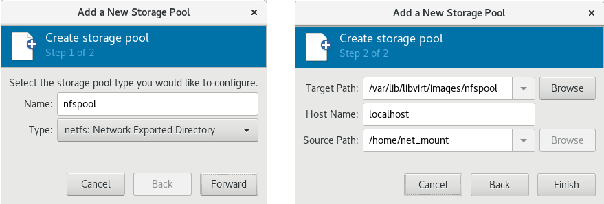
Figure 13.10. Add a new NFS-based storage pool example
13.2.3.8. vHBA-based storage pools using SCSI devices
Note
Recommendations
scsi_host# or as a WWNN/WWPN pair.
Note
scsi_host# and hardware is added to the host machine, the scsi_host# assignment may change. Therefore, it is recommended that you define a parent HBA using a WWNN/WWPN pair.
- The libvirt code can easily find the LUN's path using the virsh command output.
- Virtual machine migration requires only defining and starting a storage pool with the same vHBA name on the target machine. To do this, the vHBA LUN, libvirt storage pool and volume name must be specified in the virtual machine's XML configuration. Refer to Section 13.2.3.8, “vHBA-based storage pools using SCSI devices” for an example.
Note
'scsi' storage pool XML file using the format below. When creating a single vHBA that uses a storage pool on the same physical HBA, it is recommended to use a stable location for the <path> value, such as one of the /dev/disk/by-{path|id|uuid|label} locations on your system.
<path> field must be only /dev/, otherwise storage pool volumes are visible only to one of the vHBAs, and devices from the host cannot be exposed to multiple guests with the NPIV configuration.
Prerequisites
Procedure 13.10. Creating a vHBA
Locate HBAs on the host system
To locate the HBAs on your host system, use thevirsh nodedev-list --cap vportscommand.The following example shows a host that has two HBAs that support vHBA:#
virsh nodedev-list --cap vportsscsi_host3 scsi_host4Check the HBA's details
Use thevirsh nodedev-dumpxml HBA_devicecommand to see the HBA's details.#
virsh nodedev-dumpxml scsi_host3The output from the command lists the<name>,<wwnn>, and<wwpn>fields, which are used to create a vHBA.<max_vports>shows the maximum number of supported vHBAs. For example:<device> <name>scsi_host3</name> <path>/sys/devices/pci0000:00/0000:00:04.0/0000:10:00.0/host3</path> <parent>pci_0000_10_00_0</parent> <capability type='scsi_host'> <host>3</host> <unique_id>0</unique_id> <capability type='fc_host'> <wwnn>20000000c9848140</wwnn> <wwpn>10000000c9848140</wwpn> <fabric_wwn>2002000573de9a81</fabric_wwn> </capability> <capability type='vport_ops'> <max_vports>127</max_vports> <vports>0</vports> </capability> </capability> </device>In this example, the<max_vports>value shows there are a total 127 virtual ports available for use in the HBA configuration. The<vports>value shows the number of virtual ports currently being used. These values update after creating a vHBA.Create a vHBA host device
Create an XML file similar to one of the following for the vHBA host. In this examples, the file is named vhba_host3.xml.This example usesscsi_host3to describe the parent vHBA.# cat vhba_host3.xml <device> <parent>scsi_host3</parent> <capability type='scsi_host'> <capability type='fc_host'> </capability> </capability> </device>This example uses a WWNN/WWPN pair to describe the parent vHBA.# cat vhba_host3.xml <device> <name>vhba</name> <parent wwnn='20000000c9848140' wwpn='10000000c9848140'/> <capability type='scsi_host'> <capability type='fc_host'> </capability> </capability> </device>Note
The WWNN and WWPN values must match those in the HBA details seen in Procedure 13.10, “Creating a vHBA”.The<parent>field specifies the HBA device to associate with this vHBA device. The details in the<device>tag are used in the next step to create a new vHBA device for the host. For more information on thenodedevXML format, see the libvirt upstream pages.Create a new vHBA on the vHBA host device
To create a vHBA on the basis of vhba_host3, use thevirsh nodedev-createcommand:#
virsh nodedev-create vhba_host3.xmlNode device scsi_host5 created from vhba_host3.xmlVerify the vHBA
Verify the new vHBA's details (scsi_host5) with thevirsh nodedev-dumpxmlcommand:# virsh nodedev-dumpxml scsi_host5 <device> <name>scsi_host5</name> <path>/sys/devices/pci0000:00/0000:00:04.0/0000:10:00.0/host3/vport-3:0-0/host5</path> <parent>scsi_host3</parent> <capability type='scsi_host'> <host>5</host> <unique_id>2</unique_id> <capability type='fc_host'> <wwnn>5001a4a93526d0a1</wwnn> <wwpn>5001a4ace3ee047d</wwpn> <fabric_wwn>2002000573de9a81</fabric_wwn> </capability> </capability> </device>
Parameters
virsh pool-define-as command, and the Virtual Machine Manager application, for creating a vHBA-based storage pool.
Table 13.8. vHBA-based storage pool parameters
| Description | XML | pool-define-as |
|---|---|---|
| The type of storage pool | <pool type='scsi'> | scsi |
| The name of the storage pool | <name>name</name> | --adapter-name name |
The identifier of the vHBA. The parent attribute is optional. |
<source> |
[--adapter-parent parent] |
| The path specifying the target. This will be the path used for the storage pool. |
<target> | target path_to_pool |
Important
<path> field is /dev/, libvirt generates a unique short device path for the volume device path. For example, /dev/sdc. Otherwise, the physical host path is used. For example, /dev/disk/by-path/pci-0000:10:00.0-fc-0x5006016044602198-lun-0. The unique short device path allows the same volume to be listed in multiple guests by multiple storage pools. If the physical host path is used by multiple guests, duplicate device type warnings may occur.
Note
parent attribute can be used in the <adapter> field to identify the physical HBA parent from which the NPIV LUNs by varying paths can be used. This field, scsi_hostN, is combined with the vports and max_vports attributes to complete the parent identification. The parent, parent_wwnn, parent_wwpn, or parent_fabric_wwn attributes provide varying degrees of assurance that after the host reboots the same HBA is used.
- If no
parentis specified, libvirt uses the firstscsi_hostNadapter that supports NPIV. - If only the
parentis specified, problems can arise if additional SCSI host adapters are added to the configuration. - If
parent_wwnnorparent_wwpnis specified, after the host reboots the same HBA is used. - If
parent_fabric_wwnis used, after the host reboots an HBA on the same fabric is selected, regardless of thescsi_hostNused.
virsh to create the storage pool, continue with verifying that the storage pool was created.
Examples
parent attribute to identify the SCSI host device.
<pool type='scsi'>
<name>vhbapool_host3</name>
<source>
<adapter type='fc_host' wwnn='5001a4a93526d0a1' wwpn='5001a4ace3ee047d'/>
</source>
<target>
<path>/dev/disk/by-path</path>
</target>
</pool>
<pool type='scsi'>
<name>vhbapool_host3</name>
<source>
<adapter type='fc_host' parent='scsi_host3' wwnn='5001a4a93526d0a1' wwpn='5001a4ace3ee047d'/>
</source>
<target>
<path>/dev/disk/by-path</path>
</target>
</pool> # virsh pool-define-as vhbapool_host3 scsi --adapter-parent scsi_host3 --adapter-wwnn 5001a4a93526d0a1 --adapter-wwpn 5001a4ace3ee047d --target /dev/disk/by-path
Pool vhbapool_host3 definedNote
virsh command does not provide a way to define the parent_wwnn, parent_wwpn, or parent_fabric_wwn attributes.
Configuring a virtual machine to use a vHBA LUN
- Create a disk volume on the virtual machine in the virtual machine's XML.
- Specify the
storage pooland thestorage volumein the<source>parameter.
<disk type='volume' device='disk'> <driver name='qemu' type='raw'/> <source pool='vhbapool_host3' volume='unit:0:4:0'/> <target dev='hda' bus='ide'/> </disk>
lun device instead of a disk, see the following example:
<disk type='volume' device='lun' sgio='unfiltered'> <driver name='qemu' type='raw'/> <source pool='vhbapool_host3' volume='unit:0:4:0' mode='host'/> <target dev='sda' bus='scsi'/> <shareable /> </disk>
fast_io_fail_tmo and dev_loss_tmo options. For more information, see Reconnecting to an exposed LUN after a hardware failure.
13.2.4. Deleting Storage Pools
virsh or the Virtual Machine Manager.
13.2.4.1. Prerequisites for deleting a storage pool
13.2.4.2. Deleting storage pools using virsh
- List the defined storage pools:
#
virsh pool-list --allName State Autostart ----------------------------------------- default active yes guest_images_pool active yes - Stop the storage pool you want to delete.
#
virsh pool-destroy guest_images_disk - (Optional) For some types of storage pools, you can optionally remove the directory where the storage pool resides:
#
virsh pool-delete guest_images_disk - Remove the storage pool's definition.
#
virsh pool-undefine guest_images_disk - Confirm the pool is undefined:
#
virsh pool-list --allName State Autostart ----------------------------------------- default active yes
13.2.4.3. Deleting storage pools using Virtual Machine Manager
- Select the storage pool you want to delete in the storage pool list in the Storage tab of the Connection Details window.
- Click
 at the bottom of the Storage window. This stops the storage pool and releases any resources in use by it.
- Click
 .
.
Note
The
icon is only enabled if the storage pool is stopped.
The storage pool is deleted.
13.3. Using Storage Volumes
virsh commands and the Virtual Machine Manager.
13.3.1. Storage Volume Concepts
Note
virsh command line, this takes the form --pool storage_pool volume_name.
# virsh vol-info --pool guest_images firstimage
Name: firstimage
Type: block
Capacity: 20.00 GB
Allocation: 20.00 GB13.3.2. Creating Storage Volumes
virsh and the Virtual Machine Manager. After creating storage volumes, you can add storage devices to guests.
13.3.2.1. Creating Storage Volumes with virsh
- Define the storage volume using an XML file.a. Create a temporary XML file containing the storage volume information required for the new device.The XML file must contain specific fields including the following:
name- The name of the storage volume.allocation- The total storage allocation for the storage volume.capacity- The logical capacity of the storage volume. If the volume is sparse, this value can differ from theallocationvalue.target- The path to the storage volume on the host system and optionally its permissions and label.
The following shows an example a storage volume definition XML file. In this example, the file is saved to~/guest_volume.xml<volume> <name>volume1</name> <allocation>0</allocation> <capacity>20G</capacity> <target> <path>/var/lib/virt/images/sparse.img</path> </target> </volume>b. Use thevirsh vol-createcommand to create the storage volume based on the XML file.#
virsh vol-create guest_images_dir ~/guest_volume.xmlVol volume1 createdc. Delete the XML file created in step a. - Use the
virsh vol-create-ascommand to create the storage volume.#
virsh vol-create-as guest_images_dir volume1 20GB --allocation 0 - Clone an existing storage volume using the
virsh vol-clonecommand. Thevirsh vol-clonecommand must specify the storage pool that contains the storage volume to clone and the name of the newly created storage volume.#
virsh vol-clone --pool guest_images_dir volume1 clone1
13.3.2.2. Creating storage volumes with Virtual Machine Manager
Procedure 13.11. Creating Storage Volumes with Virtual Machine Manager
Open the storage settings
- In the Virtual Machine Manager, open the Edit menu and select Connection Details.
- Click the Storage tab in the Connection Details window.
Figure 13.11. Storage tab
The pane on the left of the Connection Details window shows a list of storage pools.
Select the storage pool in which you want to create a storage volume
In the list of storage pools, click the storage pool in which you want to create the storage volume.Any storage volumes configured on the selected storage pool appear in the Volumes pane at the bottom of the window.Add a new storage volume
Click the
button above the Volumes list. The Add a Storage Volume dialog appears.
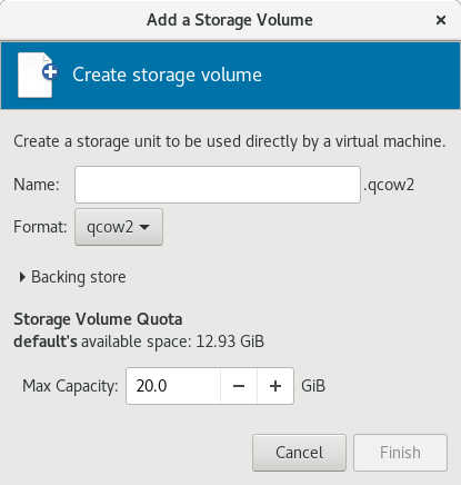
Figure 13.12. Create storage volume
Configure the storage volume
Configure the storage volume with the following parameters:- Enter a name for the storage pool in the Name field.
- Select a format for the storage volume from the Format list.
- Enter the maximum size for the storage volume in the Max Capacity field.
Finish the creation
Click . The Add a Storage Volume dialog closes, and the storage volume appears in the Volumes list.
13.3.3. Viewing Storage Volumes
virsh vol-list command to list the storage volumes in a storage pool. In the following example, the guest_images_disk contains three volumes.
#virsh vol-create-as guest_images_disk volume1 8GVol volume1 created #virsh vol-create-as guest_images_disk volume2 8GVol volume2 created #virsh vol-create-as guest_images_disk volume3 8GVol volume3 created #virsh vol-list guest_images_diskName Path ----------------------------------------- volume1 /home/VirtualMachines/guest_images_dir/volume1 volume2 /home/VirtualMachines/guest_images_dir/volume2 volume3 /home/VirtualMachines/guest_images_dir/volume3
13.3.4. Managing Data
Note
13.3.4.1. Wiping Storage Volumes
virsh vol-wipe command.
virsh vol-wipe command to wipe a storage volume:
# virsh vol-wipe new-vol vdiskvirsh vol-wipe command, refer to Section 20.32, “Deleting a Storage Volume's Contents”.
13.3.4.2. Uploading Data to a Storage Volume
virsh vol-upload command.
# virsh vol-upload --pool pool-or-uuid --offset bytes --length bytes vol-name-or-key-or-path local-filevirsh vol-upload options:
--pool pool-or-uuid- The name or UUID of the storage pool the volume is in.vol-name-or-key-or-path- The name or key or path of the volume to upload.--offset bytesThe position in the storage volume at which to start writing the data.--length length- An upper limit for the amount of data to be uploaded.Note
An error will occur if local-file is greater than the specified--length.
Example 13.1. Uploading data to a storage volume
# virsh vol-upload sde1 /tmp/data500m.empty disk-poolsde1 is a volume in the disk-pool storage pool. The data in /tmp/data500m.empty is copied to sde1.
13.3.4.3. Downloading Data to a Storage Volume
virsh vol-download command.
# vol-download --pool pool-or-uuid --offset bytes --length bytes vol-name-or-key-or-path local-filevirsh vol-download options:
--pool pool-or-uuid- The name or UUID of the storage pool that the volume is in.vol-name-or-key-or-path- The name, key, or path of the volume to download.--offset- The position in the storage volume at which to start reading the data.--length length- An upper limit for the amount of data to be downloaded.
Example 13.2. Downloading data from a storage volume
# virsh vol-download sde1 /tmp/data-sde1.tmp disk-poolsde1 is a volume in the disk-pool storage pool. The data in sde1 is downloaded to /tmp/data-sde1.tmp.
13.3.4.4. Resizing Storage Volumes
vol-resize command.
# virsh vol-resize --pool pool-or-uuid vol-name-or-path pool-or-uuid capacity --allocate --delta --shrink--pool pool-or-uuid which is the name or UUID of the storage pool the volume is in. This command also requires vol-name-or-key-or-path, the name, key, or path of the volume to resize.
--allocate is specified. Normally, capacity is the new size, but if --delta is present, then it is added to the existing size. Attempts to shrink the volume will fail unless --shrink is present.
--shrink is provided and a negative sign is not necessary. capacity is a scaled integer which defaults to bytes if there is no suffix. In addition, note that this command is only safe for storage volumes not in use by an active guest. Refer to Section 20.13.3, “Changing the Size of a Guest Virtual Machine's Block Device” for live resizing.
Example 13.3. Resizing a storage volume
# virsh vol-resize --pool disk-pool sde1 100M13.3.5. Deleting Storage Volumes
virsh or the Virtual Machine Manager.
Note
13.3.5.1. Deleting storage volumes using virsh
virsh vol-delete command. The command must specify the name or path of the storage volume and the storage pool from which the storage volume is abstracted.
# virsh vol-delete volume_name --pool guest_images_dir
vol volume_name deleted13.3.5.2. Deleting storage volumes using Virtual Machine Manager
Procedure 13.12. Deleting Storage Volumes with Virtual Machine Manager
Open the storage settings
- In the Virtual Machine Manager, open the Edit menu and select Connection Details.
- Click the Storage tab in the Connection Details window.
Figure 13.13. Storage tab
The pane on the left of the Connection Details window shows a list of storage pools.
Select the storage volume you want to delete
- In the list of storage pools, click the storage pool from which the storage volume is abstracted.A list of storage volumes configured on the selected storage pool appear in the Volumes pane at the bottom of the window.
- Select the storage volume you want to delete.
Delete the storage volume
- Click the
button (above the Volumes list). A confirmation dialog appears.
- Click . The selected storage volume is deleted.
13.3.6. Adding Storage Devices to Guests
virsh or Virtual Machine Manager.
13.3.6.1. Adding Storage Devices to Guests Using virsh
attach-disk command. The arguments that contain information about the disk to add can be specified in an XML file or on the command line.
<disk type='file' device='disk>'> <driver name='qemu' type='raw' cache='none'/> <source file='/var/lib/libvirt/images/FileName.img'/> <target dev='vdb' bus='virtio'/> </disk>
NewStorage.xml.
# virsh attach-disk --config Guest1 ~/NewStorage.xml# virsh attach-disk --config Guest1 --source /var/lib/libvirt/images/FileName.img --target vdb13.3.6.2. Adding Storage Devices to Guests Using Virtual Machine Manager
13.3.6.2.1. Adding a storage volume to a guest
Open Virtual Machine Manager to the virtual machine hardware details window
Open virt-manager by executing thevirt-managercommand as root or opening Applications → System Tools → Virtual Machine Manager.Figure 13.14. The Virtual Machine Manager window
Select the guest virtual machine to which you want to add a storage volume.Click . The Virtual Machine window opens.Click
. The hardware details window appears.
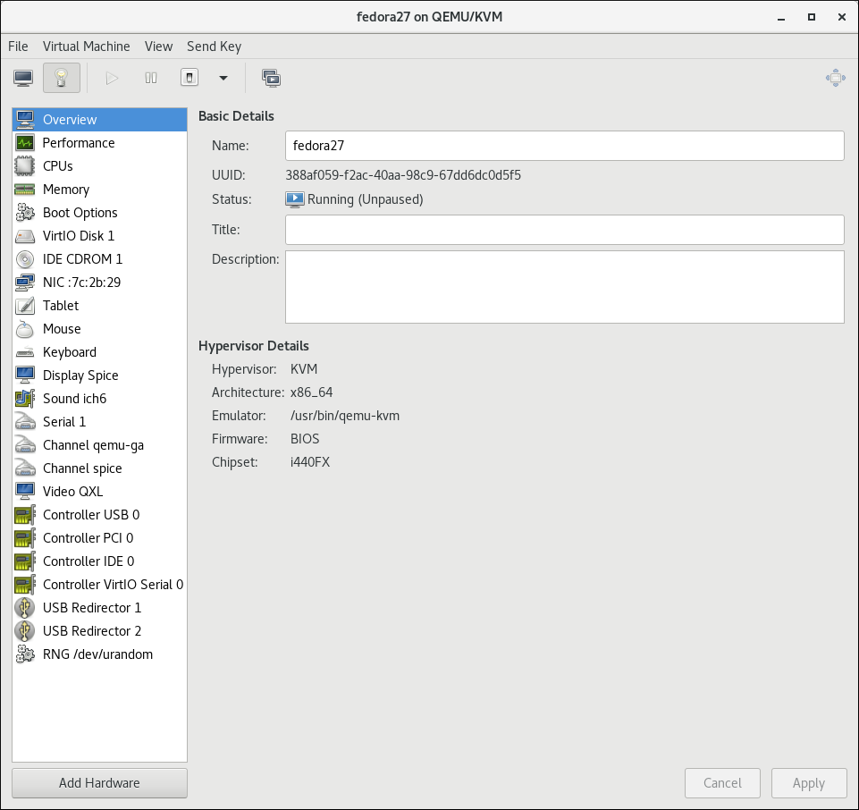
Figure 13.15. The Hardware Details window
Open the Add New Virtual Hardware window
Click . The Add New Virtual Hardware window appears.Ensure that Storage is selected in the hardware type pane.Figure 13.16. The Add New Virtual Hardware window
View a list of storage volumes
Select the Select or create custom storage option button.Click . The Choose Storage Volume dialog appears.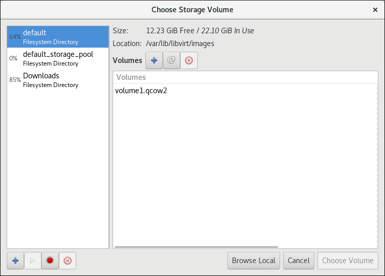
Figure 13.17. The Select Storage Volume window
Select a storage volume
Select a storage pool from the list on the left side of the Select Storage Volume window. A list of storage volumes in the selected storage pool appears in the Volumes list.Note
You can create a storage pool from the Select Storage Volume window. For more information, see Section 13.2.2.2, “Creating storage pools with Virtual Machine Manager”.Select a storage volume from the Volumes list.Note
You can create a storage volume from the Select Storage Volume window. For more information, see Section 13.3.2.2, “Creating storage volumes with Virtual Machine Manager”.Click . The Select Storage Volume window closes.Configure the storage volume
Select a device type from the Device type list. Available types are: Disk device, Floppy device, and LUN Passthrough.Select a bus type from the Bus type list. The available bus types are dependent on the selected device type.Select a cache mode from the Cache mode list. Available cache modes are: Hypervisor default, none, writethrough, writeback, directsync, unsafeClick . The Add New Virtual Hardware window closes.
13.3.6.2.2. Adding default storage to a guest
/var/lib/libvirt/images/ directory.
Open Virtual Machine Manager to the virtual machine hardware details window
Open virt-manager by executing thevirt-managercommand as root or opening Applications → System Tools → Virtual Machine Manager.Figure 13.18. The Virtual Machine Manager window
Select the guest virtual machine to which you want to add a storage volume.Click . The Virtual Machine window opens.Click
. The hardware details window appears.
Figure 13.19. The Hardware Details window
Open the Add New Virtual Hardware window
Click . The Add New Virtual Hardware window appears.Ensure that Storage is selected in the hardware type pane.Figure 13.20. The Add New Virtual Hardware window
Create a disk for the guest
Ensure that the Create a disk image for the virtual machine option.Enter the size of the disk to create in the textbox below the Create a disk image for the virtual machine option button.Click . The Add New Virtual Hardware window closes.
13.3.6.3. Adding SCSI LUN-based Storage to a Guest
Important
sgio attribute controls whether unprivileged SCSI Generical I/O (SG_IO) commands are filtered for a device='lun' disk. The sgio attribute can be specified as 'filtered' or 'unfiltered', but must be set to 'unfiltered' to allow SG_IO ioctl commands to be passed through on the guest in a persistent reservation.
sgio='unfiltered', the <shareable> element must be set to share a LUN between guests. The sgio attribute defaults to 'filtered' if not specified.
<disk> XML attribute device='lun' is valid for the following guest disk configurations:
type='block'for<source dev='/dev/disk/by-{path|id|uuid|label}'/><disk type='block' device='lun' sgio='unfiltered'> <driver name='qemu' type='raw'/> <source dev='/dev/disk/by-path/pci-0000\:04\:00.1-fc-0x203400a0b85ad1d7-lun-0'/> <target dev='sda' bus='scsi'/> <shareable/> </disk>
Note
The backslashes prior to the colons in the<source>device name are required.type='network'for<source protocol='iscsi'... /><disk type='network' device='lun' sgio='unfiltered'> <driver name='qemu' type='raw'/> <source protocol='iscsi' name='iqn.2013-07.com.example:iscsi-net-pool/1'> <host name='example.com' port='3260'/> <auth username='myuser'> <secret type='iscsi' usage='libvirtiscsi'/> </auth> </source> <target dev='sda' bus='scsi'/> <shareable/> </disk>type='volume'when using an iSCSI or a NPIV/vHBA source pool as the SCSI source pool.The following example XML shows a guest using an iSCSI source pool (named iscsi-net-pool) as the SCSI source pool:<disk type='volume' device='lun' sgio='unfiltered'> <driver name='qemu' type='raw'/> <source pool='iscsi-net-pool' volume='unit:0:0:1' mode='host'/> <target dev='sda' bus='scsi'/> <shareable/> </disk>
Note
Themode=option within the<source>tag is optional, but if used, it must be set to'host'and not'direct'. When set to'host', libvirt will find the path to the device on the local host. When set to'direct', libvirt will generate the path to the device using the source pool's source host data.The iSCSI pool (iscsi-net-pool) in the example above will have a similar configuration to the following:# virsh pool-dumpxml iscsi-net-pool <pool type='iscsi'> <name>iscsi-net-pool</name> <capacity unit='bytes'>11274289152</capacity> <allocation unit='bytes'>11274289152</allocation> <available unit='bytes'>0</available> <source> <host name='192.168.122.1' port='3260'/> <device path='iqn.2013-12.com.example:iscsi-chap-netpool'/> <auth type='chap' username='redhat'> <secret usage='libvirtiscsi'/> </auth> </source> <target> <path>/dev/disk/by-path</path> <permissions> <mode>0755</mode> </permissions> </target> </pool>To verify the details of the available LUNs in the iSCSI source pool, enter the following command:# virsh vol-list iscsi-net-pool Name Path ------------------------------------------------------------------------------ unit:0:0:1 /dev/disk/by-path/ip-192.168.122.1:3260-iscsi-iqn.2013-12.com.example:iscsi-chap-netpool-lun-1 unit:0:0:2 /dev/disk/by-path/ip-192.168.122.1:3260-iscsi-iqn.2013-12.com.example:iscsi-chap-netpool-lun-2
type='volume'when using a NPIV/vHBA source pool as the SCSI source pool.The following example XML shows a guest using a NPIV/vHBA source pool (named vhbapool_host3) as the SCSI source pool:<disk type='volume' device='lun' sgio='unfiltered'> <driver name='qemu' type='raw'/> <source pool='vhbapool_host3' volume='unit:0:1:0'/> <target dev='sda' bus='scsi'/> <shareable/> </disk>
The NPIV/vHBA pool (vhbapool_host3) in the example above will have a similar configuration to:# virsh pool-dumpxml vhbapool_host3 <pool type='scsi'> <name>vhbapool_host3</name> <capacity unit='bytes'>0</capacity> <allocation unit='bytes'>0</allocation> <available unit='bytes'>0</available> <source> <adapter type='fc_host' parent='scsi_host3' managed='yes' wwnn='5001a4a93526d0a1' wwpn='5001a4ace3ee045d'/> </source> <target> <path>/dev/disk/by-path</path> <permissions> <mode>0700</mode> <owner>0</owner> <group>0</group> </permissions> </target> </pool>To verify the details of the available LUNs on the vHBA, enter the following command:# virsh vol-list vhbapool_host3 Name Path ------------------------------------------------------------------------------ unit:0:0:0 /dev/disk/by-path/pci-0000:10:00.0-fc-0x5006016044602198-lun-0 unit:0:1:0 /dev/disk/by-path/pci-0000:10:00.0-fc-0x5006016844602198-lun-0
For more information on using a NPIV vHBA with SCSI devices, see Section 13.2.3.8, “vHBA-based storage pools using SCSI devices”.
<disk device='lun'> guest disk configurations can be attached with this method. Substitute configurations according to your environment.
Procedure 13.13. Attaching SCSI LUN-based storage to a guest
- Create the device file by writing a <disk> element in a new file, and save this file with an XML extension (in this example, sda.xml):
# cat sda.xml <disk type='volume' device='lun' sgio='unfiltered'> <driver name='qemu' type='raw'/> <source pool='vhbapool_host3' volume='unit:0:1:0'/> <target dev='sda' bus='scsi'/> <shareable/> </disk>
- Associate the device created in sda.xml with your guest virtual machine (Guest1, for example):
#
virsh attach-device --config Guest1 ~/sda.xmlNote
Running thevirsh attach-devicecommand with the--configoption requires a guest reboot to add the device permanently to the guest. Alternatively, the--persistentoption can be used instead of--config, which can also be used to hotplug the device to a guest.
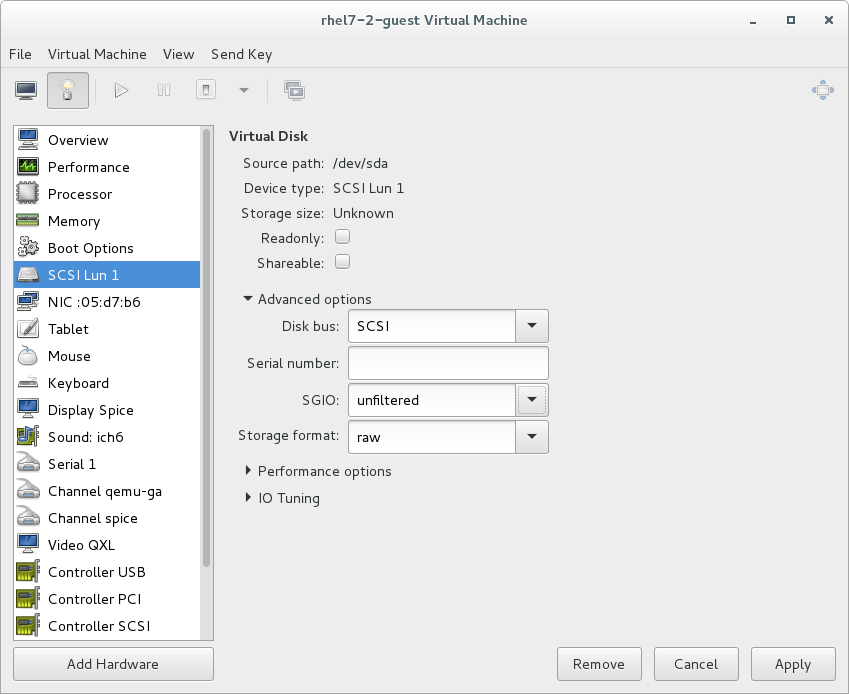
Figure 13.21. Configuring SCSI LUN storage with virt-manager
Reconnecting to an exposed LUN after a hardware failure
dev_loss_tmo and fast_io_fail_tmo kernel options:
dev_loss_tmocontrols how long the SCSI layer waits after a SCSI device fails before marking it as failed. To prevent a timeout, it is recommended to set the option to the maximum value, which is2147483647.fast_io_fail_tmocontrols how long the SCSI layer waits after a SCSI device fails before failing back to the I/O. To ensure thatdev_loss_tmois not ignored by the kernel, set this option's value to any number lower than the value ofdev_loss_tmo.
dev_loss_tmo and fast_io_fail, do one of the following:
- Edit the
/etc/multipath.conffile, and set the values in thedefaultssection:defaults { ... fast_io_fail_tmo 20 dev_loss_tmo infinity } - Set
dev_loss_tmoandfast_io_failon the level of the FC host or remote port, for example as follows:#
echo 20 > /sys/devices/pci0000:00/0000:00:06.0/0000:13:00.0/host1/rport-1:0-0/fc_remote_ports/rport-1:0-0/fast_io_fail_tmo#echo 2147483647 > /sys/devices/pci0000:00/0000:00:06.0/0000:13:00.0/host1/rport-1:0-0/fc_remote_ports/rport-1:0-0/dev_loss_tmo
dev_loss_tmo and fast_io_fail are active, use the following command:
# find /sys -name dev_loss_tmo -print -exec cat {} \;pci0000:00/0000:00:06.0/0000:13:00.0/host1/rport-1:0-0/fc_remote_ports/rport-1:0-0:
# find /sys -name dev_loss_tmo -print -exec cat {} \;
...
/sys/devices/pci0000:00/0000:00:06.0/0000:13:00.0/host1/rport-1:0-0/fc_remote_ports/rport-1:0-0/dev_loss_tmo
2147483647
...
13.3.6.4. Managing Storage Controllers in a Guest Virtual Machine
Procedure 13.14. Creating a virtual SCSI controller
- Display the configuration of the guest virtual machine (
Guest1) and look for a pre-existing SCSI controller:#
virsh dumpxml Guest1 | grep controller.*scsiIf a device controller is present, the command will output one or more lines similar to the following:<controller type='scsi' model='virtio-scsi' index='0'/>
- If the previous step did not show a device controller, create the description for one in a new file and add it to the virtual machine, using the following steps:
- Create the device controller by writing a
<controller>element in a new file and save this file with an XML extension.virtio-scsi-controller.xml, for example.<controller type='scsi' model='virtio-scsi'/>
- Associate the device controller you just created in
virtio-scsi-controller.xmlwith your guest virtual machine (Guest1, for example):#
virsh attach-device --config Guest1 ~/virtio-scsi-controller.xmlIn this example the--configoption behaves the same as it does for disks. See Section 13.3.6, “Adding Storage Devices to Guests” for more information.
- Add a new SCSI disk or CD-ROM. The new disk can be added using the methods in Section 13.3.6, “Adding Storage Devices to Guests”. In order to create a SCSI disk, specify a target device name that starts with sd.
Note
The supported limit for each controller is 1024 virtio-scsi disks, but it is possible that other available resources in the host (such as file descriptors) are exhausted with fewer disks.For more information, see the following Red Hat Enterprise Linux 6 whitepaper: The next-generation storage interface for the Red Hat Enterprise Linux Kernel Virtual Machine: virtio-scsi.#
virsh attach-disk Guest1 /var/lib/libvirt/images/FileName.img sdb --cache noneDepending on the version of the driver in the guest virtual machine, the new disk may not be detected immediately by a running guest virtual machine. Follow the steps in the Red Hat Enterprise Linux Storage Administration Guide.
13.3.7. Removing Storage Devices from Guests
virsh or Virtual Machine Manager.
13.3.7.1. Removing Storage from a Virtual Machine with virsh
# virsh detach-disk Guest1 vdb13.3.7.2. Removing Storage from a Virtual Machine with Virtual Machine Manager
Procedure 13.15. Removing storage from a virtual machine with Virtual Machine Manager
Open Virtual Machine Manager to the virtual machine hardware details window
Open virt-manager by executing thevirt-managercommand as root or opening Applications → System Tools → Virtual Machine Manager.Select the guest virtual machine from which you want to remove a storage device.Click . The Virtual Machine window opens.Click
. The hardware details window appears.
Remove the storage from the guest virtual machine
Select the storage device from the list of hardware on the left side of the hardware details pane.Click . A confirmation dialog appears.Click . The storage is removed from the guest virtual machine.
Chapter 14. Using qemu-img
Warning
14.1. Checking the Disk Image
# qemu-img check [-f format] imgnameNote
14.2. Committing Changes to an Image
qemu-img commit command. Optionally, specify the file's format type (fmt).
# qemu-img commit [-f fmt] [-t cache] imgname14.3. Comparing Images
qemu-img compare command. Optionally, specify the files' format types (fmt). The images can have different formats and settings.
-s option, the images are not considered identical if the image sizes differ or a sector is allocated in one image and is not allocated in the second one.
# qemu-img compare [-f fmt] [-F fmt] [-p] [-s] [-q] imgname1 imgname2qemu-img compare command exits with one of the following exit codes:
0- The images are identical1- The images are different2- There was an error opening one of the images3- There was an error checking a sector allocation4- There was an error reading the data
14.4. Mapping an Image
qemu-img map command, your can dump the metadata of the specified image file (imgname) and its backing file chain. The dump shows the allocation state of every sector in the (imgname) with the topmost file that allocates it in the backing file chain. Optionally, specify the file's format type (fmt).
# qemu-img map [-f fmt] [--output=fmt] imgnamehuman format and the json format:
14.4.1. The human Format
human) only dumps non-zero, allocated parts of the file. The output identifies a file from where data can be read and the offset in the file. Each line includes four fields. The following shows an example of an output:
Offset Length Mapped to File 0 0x20000 0x50000 /tmp/overlay.qcow2 0x100000 0x10000 0x95380000 /tmp/backing.qcow2
0x20000 (131072) bytes starting at offset 0 in the image are available in tmp/overlay.qcow2 (opened in raw format) starting at offset 0x50000 (327680). Data that is compressed, encrypted, or otherwise not available in raw format causes an error if human format is specified.
Note
human format in scripts.
14.4.2. The json Format
json option is specified, the output returns an array of dictionaries in JSON format. In addition to the information provided in the human option, the output includes the following information:
data- A Boolean field that shows whether or not the sectors contain datazero- A Boolean field that shows whether or not the data is known to read as zerodepth- The depth of the backing file offilename
Note
json option is specified, the offset field is optional.
qemu-img map command and additional options, see the relevant man page.
14.5. Amending an Image
# qemu-img amend [-p] [-f fmt] [-t cache] -o options filename
Note
14.6. Converting an Existing Image to Another Format
convert option is used to convert one recognized image format to another image format. For a list of accepted formats, see Section 14.12, “Supported qemu-img Formats”.
# qemu-img convert [-c] [-p] [-f fmt] [-t cache] [-O output_fmt] [-o options] [-S sparse_size] filename output_filename-p parameter shows the progress of the command (optional and not for every command) and -S flag allows for the creation of a sparse file, which is included within the disk image. Sparse files in all purposes function like a standard file, except that the physical blocks that only contain zeros (that is, nothing). When the Operating System sees this file, it treats it as it exists and takes up actual disk space, even though in reality it does not take any. This is particularly helpful when creating a disk for a guest virtual machine as this gives the appearance that the disk has taken much more disk space than it has. For example, if you set -S to 50Gb on a disk image that is 10Gb, then your 10Gb of disk space will appear to be 60Gb in size even though only 10Gb is actually being used.
filename to disk image output_filename using format output_format. The disk image can be optionally compressed with the -c option, or encrypted with the -o option by setting -o encryption. Note that the options available with the -o parameter differ with the selected format.
qcow2 and qcow2 format supports encryption or compression. qcow2 encryption uses the AES format with secure 128-bit keys. qcow2 compression is read-only, so if a compressed sector is converted from qcow2 format, it is written to the new format as uncompressed data.
qcow or cow. The empty sectors are detected and suppressed from the destination image.
14.7. Creating and Formatting New Images or Devices
size and format format.
# qemu-img create [-f format] [-o options] filename [size]-o backing_file=filename, the image will only record differences between itself and the base image. The backing file will not be modified unless you use the commit command. No size needs to be specified in this case.
14.8. Displaying Image Information
info parameter displays information about a disk image filename. The format for the info option is as follows:
# qemu-img info [-f format] filenameqemu-img. You can check that the image in use is the one that matches the output of the qemu-img info command with the qemu-img check command.
# qemu-img info /dev/vg-90.100-sluo/lv-90-100-sluo
image: /dev/vg-90.100-sluo/lv-90-100-sluo
file format: qcow2
virtual size: 20G (21474836480 bytes)
disk size: 0
cluster_size: 65536
14.9. Rebasing a Backing File of an Image
qemu-img rebase changes the backing file of an image.
# qemu-img rebase [-f fmt] [-t cache] [-p] [-u] -b backing_file [-F backing_fmt] filenameNote
safe and unsafe.
safe mode is used by default and performs a real rebase operation. The new backing file may differ from the old one and the qemu-img rebase command will take care of keeping the guest virtual machine-visible content of filename unchanged. In order to achieve this, any clusters that differ between backing_file and old backing file of filename are merged into filename before making any changes to the backing file.
safe mode is an expensive operation, comparable to converting an image. The old backing file is required for it to complete successfully.
unsafe mode is used if the -u option is passed to qemu-img rebase. In this mode, only the backing file name and format of filename is changed, without any checks taking place on the file contents. Make sure the new backing file is specified correctly or the guest-visible content of the image will be corrupted.
14.10. Re-sizing the Disk Image
# qemu-img resize filename size+ to grow, or - to reduce the size of the disk image by that number of bytes. Adding a unit suffix allows you to set the image size in kilobytes (K), megabytes (M), gigabytes (G) or terabytes (T).
# qemu-img resize filename [+|-]size[K|M|G|T]Warning
14.11. Listing, Creating, Applying, and Deleting a Snapshot
qemu-img snapshot command you can list, apply, create, or delete an existing snapshot (snapshot) of specified image (filename).
# qemu-img snapshot [ -l | -a snapshot | -c snapshot | -d snapshot ] filename-llists all snapshots associated with the specified disk image.- The apply option,
-a, reverts the disk image (filename) to the state of a previously saved snapshot. -ccreates a snapshot (snapshot) of an image (filename).-ddeletes the specified snapshot.
14.12. Supported qemu-img Formats
raw- Raw disk image format (default). This can be the fastest file-based format. If your file system supports holes (for example in ext2 or ext3 ), then only the written sectors will reserve space. Useqemu-img infoto obtain the real size used by the image orls -lson Unix/Linux. Although Raw images give optimal performance, only very basic features are available with a Raw image. For example, no snapshots are available.qcow2- QEMU image format, the most versatile format with the best feature set. Use it to have optional AES encryption, zlib-based compression, support of multiple VM snapshots, and smaller images, which are useful on file systems that do not support holes . Note that this expansive feature set comes at the cost of performance.Although only the formats above can be used to run on a guest virtual machine or host physical machine, qemu-img also recognizes and supports the following formats in order to convert from them into eitherraw, orqcow2format. The format of an image is usually detected automatically. In addition to converting these formats intoraworqcow2, they can be converted back fromraworqcow2to the original format. Note that the qcow2 version supplied with Red Hat Enterprise Linux 7 is 1.1. The format that is supplied with previous versions of Red Hat Enterprise Linux will be 0.10. You can revert image files to previous versions of qcow2. To know which version you are using, runqemu-img info qcow2 [imagefilename.img]command. To change the qcow version see Section 23.19.2, “Setting Target Elements”.bochs- Bochs disk image format.cloop- Linux Compressed Loop image, useful only to reuse directly compressed CD-ROM images present for example in the Knoppix CD-ROMs.cow- User Mode Linux Copy On Write image format. Thecowformat is included only for compatibility with previous versions.dmg- Mac disk image format.nbd- Network block device.parallels- Parallels virtualization disk image format.qcow- Old QEMU image format. Only included for compatibility with older versions.qed- Old QEMU image format. Only included for compatibility with older versions.vdi- Oracle VM VirtualBox hard disk image format.vhdx- Microsoft Hyper-V virtual hard disk-X disk image format.vmdk- VMware 3 and 4 compatible image format.vvfat- Virtual VFAT disk image format.
Chapter 15. KVM Migration
15.1. Migration Definition and Benefits
- Load balancing
- Guest virtual machines can be moved to host physical machines with lower usage if their host machine becomes overloaded, or if another host machine is under-utilized.
- Hardware independence
- When you need to upgrade, add, or remove hardware devices on the host physical machine, you can safely relocate guest virtual machines to other host physical machines. This means that guest virtual machines do not experience any downtime for hardware improvements.
- Energy saving
- Virtual machines can be redistributed to other host physical machines, and the unloaded host systems can thus be powered off to save energy and cut costs in low usage periods.
- Geographic migration
- Virtual machines can be moved to another location for lower latency or when required by other reasons.
15.2. Migration Requirements and Limitations
Migration requirements
- A guest virtual machine installed on shared storage using one of the following protocols:
- Fibre Channel-based LUNs
- iSCSI
- NFS
- GFS2
- SCSI RDMA protocols (SCSI RCP): the block export protocol used in Infiniband and 10GbE iWARP adapters
- Make sure that the
libvirtdservice is enabled and running.#
systemctl enable libvirtd.service#systemctl restart libvirtd.service - The ability to migrate effectively is dependant on the parameter setting in the
/etc/libvirt/libvirtd.conffile. To edit this file, use the following procedure:Procedure 15.1. Configuring libvirtd.conf
- Opening the
libvirtd.confrequires running the command as root:#
vim /etc/libvirt/libvirtd.conf - Change the parameters as needed and save the file.
- Restart the
libvirtdservice:#
systemctl restart libvirtd
- The migration platforms and versions should be checked against Table 15.1, “Live Migration Compatibility”
- Use a separate system exporting the shared storage medium. Storage should not reside on either of the two host physical machines used for the migration.
- Shared storage must mount at the same location on source and destination systems. The mounted directory names must be identical. Although it is possible to keep the images using different paths, it is not recommended. Note that, if you intend to use virt-manager to perform the migration, the path names must be identical. If you intend to use virsh to perform the migration, different network configurations and mount directories can be used with the help of
--xmloption or pre-hooks . For more information on pre-hooks, see the libvirt upstream documentation, and for more information on the XML option, see Chapter 23, Manipulating the Domain XML. - When migration is attempted on an existing guest virtual machine in a public bridge+tap network, the source and destination host machines must be located on the same network. Otherwise, the guest virtual machine network will not operate after migration.
Migration Limitations
- Guest virtual machine migration has the following limitations when used on Red Hat Enterprise Linux with virtualization technology based on KVM:
- Point to point migration – must be done manually to designate destination hypervisor from originating hypervisor
- No validation or roll-back is available
- Determination of target may only be done manually
- Storage migration cannot be performed live on Red Hat Enterprise Linux 7, but you can migrate storage while the guest virtual machine is powered down. Live storage migration is available on Red Hat Virtualization. Call your service representative for details.
Note
15.3. Live Migration and Red Hat Enterprise Linux Version Compatibility
Table 15.1. Live Migration Compatibility
| Migration Method | Release Type | Example | Live Migration Support | Notes |
|---|---|---|---|---|
| Forward | Major release | 6.5+ → 7.x | Fully supported | Any issues should be reported |
| Backward | Major release | 7.x → 6.y | Not supported | |
| Forward | Minor release | 7.x → 7.y (7.0 → 7.1) | Fully supported | Any issues should be reported |
| Backward | Minor release | 7.y → 7.x (7.1 → 7.0) | Fully supported | Any issues should be reported |
Troubleshooting problems with migration
- Issues with the migration protocol — If backward migration ends with "unknown section error", repeating the migration process can repair the issue as it may be a transient error. If not, report the problem.
- Issues with audio devices — When migrating from Red Hat Enterprise Linux 6.x to Red Hat Enterprise Linux 7.y, note that the es1370 audio card is no longer supported. Use the ac97 audio card instead.
- Issues with network cards — When migrating from Red Hat Enterprise Linux 6.x to Red Hat Enterprise Linux 7.y, note that the pcnet and ne2k_pci network cards are no longer supported. Use the virtio-net network device instead.
Configure shared storage and install a guest virtual machine on the shared storage.
15.5. Live KVM Migration with virsh
virsh command. The migrate command accepts parameters in the following format:
# virsh migrate --live GuestName DestinationURLGuestName parameter represents the name of the guest virtual machine which you want to migrate.
DestinationURL parameter is the connection URL of the destination host physical machine. The destination system must run the same version of Red Hat Enterprise Linux, be using the same hypervisor and have libvirt running.
Note
DestinationURL parameter for normal migration and peer2peer migration has different semantics:
- normal migration: the
DestinationURLis the URL of the target host physical machine as seen from the source guest virtual machine. - peer2peer migration:
DestinationURLis the URL of the target host physical machine as seen from the source host physical machine.
Important
This example migrates from host1.example.com to host2.example.com. Change the host physical machine names for your environment. This example migrates a virtual machine named guest1-rhel6-64.
Verify the guest virtual machine is running
From the source system,host1.example.com, verifyguest1-rhel6-64is running:[root@host1 ~]#
virsh listId Name State ---------------------------------- 10 guest1-rhel6-64 runningMigrate the guest virtual machine
Execute the following command to live migrate the guest virtual machine to the destination,host2.example.com. Append/systemto the end of the destination URL to tell libvirt that you need full access.#
virsh migrate --liveguest1-rhel7-64 qemu+ssh://host2.example.com/systemOnce the command is entered you will be prompted for the root password of the destination system.Wait
The migration may take some time depending on load and the size of the guest virtual machine.virshonly reports errors. The guest virtual machine continues to run on the source host physical machine until fully migrated.Verify the guest virtual machine has arrived at the destination host
From the destination system,host2.example.com, verifyguest1-rhel7-64is running:[root@host2 ~]#
virsh listId Name State ---------------------------------- 10 guest1-rhel7-64 running
Note
Note
# virsh migrate --offline --persistent
15.5.1. Additional Tips for Migration with virsh
- Open the libvirtd.conf file as described in Procedure 15.1, “Configuring libvirtd.conf”.
- Look for the Processing controls section.
################################################################# # # Processing controls # # The maximum number of concurrent client connections to allow # over all sockets combined. #max_clients = 5000 # The maximum length of queue of connections waiting to be # accepted by the daemon. Note, that some protocols supporting # retransmission may obey this so that a later reattempt at # connection succeeds. #max_queued_clients = 1000 # The minimum limit sets the number of workers to start up # initially. If the number of active clients exceeds this, # then more threads are spawned, upto max_workers limit. # Typically you'd want max_workers to equal maximum number # of clients allowed #min_workers = 5 #max_workers = 20 # The number of priority workers. If all workers from above # pool will stuck, some calls marked as high priority # (notably domainDestroy) can be executed in this pool. #prio_workers = 5 # Total global limit on concurrent RPC calls. Should be # at least as large as max_workers. Beyond this, RPC requests # will be read into memory and queued. This directly impact # memory usage, currently each request requires 256 KB of # memory. So by default upto 5 MB of memory is used # # XXX this isn't actually enforced yet, only the per-client # limit is used so far #max_requests = 20 # Limit on concurrent requests from a single client # connection. To avoid one client monopolizing the server # this should be a small fraction of the global max_requests # and max_workers parameter #max_client_requests = 5 #################################################################
- Change the
max_clientsandmax_workersparameters settings. It is recommended that the number be the same in both parameters. Themax_clientswill use 2 clients per migration (one per side) andmax_workerswill use 1 worker on the source and 0 workers on the destination during the perform phase and 1 worker on the destination during the finish phase.Important
Themax_clientsandmax_workersparameters settings are affected by all guest virtual machine connections to the libvirtd service. This means that any user that is using the same guest virtual machine and is performing a migration at the same time will also obey the limits set in themax_clientsandmax_workersparameters settings. This is why the maximum value needs to be considered carefully before performing a concurrent live migration.Important
Themax_clientsparameter controls how many clients are allowed to connect to libvirt. When a large number of containers are started at once, this limit can be easily reached and exceeded. The value of themax_clientsparameter could be increased to avoid this, but doing so can leave the system more vulnerable to denial of service (DoS) attacks against instances. To alleviate this problem, a newmax_anonymous_clientssetting has been introduced in Red Hat Enterprise Linux 7.0 that specifies a limit of connections which are accepted but not yet authenticated. You can implement a combination ofmax_clientsandmax_anonymous_clientsto suit your workload. - Save the file and restart the service.
Note
There may be cases where a migration connection drops because there are too many ssh sessions that have been started, but not yet authenticated. By default,sshdallows only 10 sessions to be in a "pre-authenticated state" at any time. This setting is controlled by theMaxStartupsparameter in the sshd configuration file (located here:/etc/ssh/sshd_config), which may require some adjustment. Adjusting this parameter should be done with caution as the limitation is put in place to prevent DoS attacks (and over-use of resources in general). Setting this value too high will negate its purpose. To change this parameter, edit the file/etc/ssh/sshd_config, remove the#from the beginning of theMaxStartupsline, and change the10(default value) to a higher number. Remember to save the file and restart thesshdservice. For more information, see thesshd_configman page.
15.5.2. Additional Options for the virsh migrate Command
--live, virsh migrate accepts the following options:
--direct- used for direct migration--p2p- used for peer-to-peer migration--tunneled- used for tunneled migration--offline- migrates domain definition without starting the domain on destination and without stopping it on source host. Offline migration may be used with inactive domains and it must be used with the--persistentoption.--persistent- leaves the domain persistent on destination host physical machine--undefinesource- undefines the domain on the source host physical machine--suspend- leaves the domain paused on the destination host physical machine--change-protection- enforces that no incompatible configuration changes will be made to the domain while the migration is underway; this flag is implicitly enabled when supported by the hypervisor, but can be explicitly used to reject the migration if the hypervisor lacks change protection support.--unsafe- forces the migration to occur, ignoring all safety procedures.--verbose- displays the progress of migration as it is occurring--compressed- activates compression of memory pages that have to be transferred repeatedly during live migration.--abort-on-error- cancels the migration if a soft error (for example I/O error) happens during the migration.--domain [name]- sets the domain name, id or uuid.--desturi [URI]- connection URI of the destination host as seen from the client (normal migration) or source (p2p migration).--migrateuri [URI]- the migration URI, which can usually be omitted.--graphicsuri [URI]- graphics URI to be used for seamless graphics migration.--listen-address [address]- sets the listen address that the hypervisor on the destination side should bind to for incoming migration.--timeout [seconds]- forces a guest virtual machine to suspend when the live migration counter exceeds N seconds. It can only be used with a live migration. Once the timeout is initiated, the migration continues on the suspended guest virtual machine.--dname [newname]- is used for renaming the domain during migration, which also usually can be omitted--xml [filename]- the filename indicated can be used to supply an alternative XML file for use on the destination to supply a larger set of changes to any host-specific portions of the domain XML, such as accounting for naming differences between source and destination in accessing underlying storage. This option is usually omitted.--migrate-disks [disk_identifiers]- this option can be used to select which disks are copied during the migration. This allows for more efficient live migration when copying certain disks is undesirable, such as when they already exist on the destination, or when they are no longer useful. [disk_identifiers] should be replaced by a comma-separated list of disks to be migrated, identified by their arguments found in the<target dev= />line of the Domain XML file.
virsh migrate-setmaxdowntime [domain] [downtime]- will set a maximum tolerable downtime for a domain which is being live-migrated to another host. The specified downtime is in milliseconds. The domain specified must be the same domain that is being migrated.virsh migrate-compcache [domain]- will set and or get the size of the cache in bytes which is used for compressing repeatedly transferred memory pages during a live migration. When the--size--sizeis not used the command displays the current size of the compression cache. When--sizeis used, and specified in bytes, the hypervisor is asked to change compression to match the indicated size, following which the current size is displayed. The--sizeargument is supposed to be used while the domain is being live migrated as a reaction to the migration progress and increasing number of compression cache misses obtained from thedomjobinfo.virsh migrate-setspeed [domain] [bandwidth]- sets the migration bandwidth in Mib/sec for the specified domain which is being migrated to another host.virsh migrate-getspeed [domain]- gets the maximum migration bandwidth that is available in Mib/sec for the specified domain.
15.6. Migrating with virt-manager
virt-manager from one host physical machine to another.
Connect to the target host physical machine
In the virt-manager interface, connect to the target host physical machine by selecting the menu, then click .Add connection
The Add Connection window appears.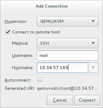
Figure 15.1. Adding a connection to the target host physical machine
Enter the following details:- Hypervisor: Select .
- Method: Select the connection method.
- Username: Enter the user name for the remote host physical machine.
- Hostname: Enter the host name for the remote host physical machine.
Note
For more information on the connection options, see Section 19.5, “Adding a Remote Connection”.Click . An SSH connection is used in this example, so the specified user's password must be entered in the next step.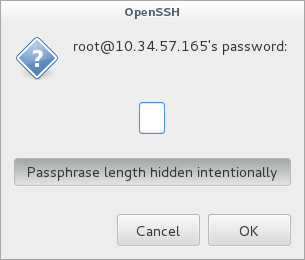
Figure 15.2. Enter password
Configure shared storage
Ensure that both the source and the target host are sharing storage, for example using NFS.Migrate guest virtual machines
Right-click the guest that is to be migrated, and click .In the field, use the drop-down list to select the host physical machine you wish to migrate the guest virtual machine to and click .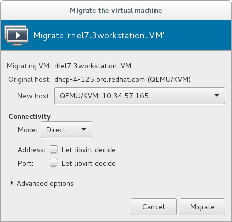
Figure 15.3. Choosing the destination host physical machine and starting the migration process
A progress window appears.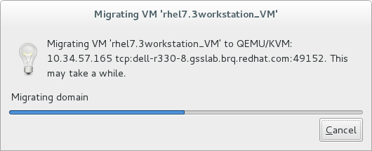
Figure 15.4. Progress window
If the migration finishes without any problems, virt-manager displays the newly migrated guest virtual machine running in the destination host.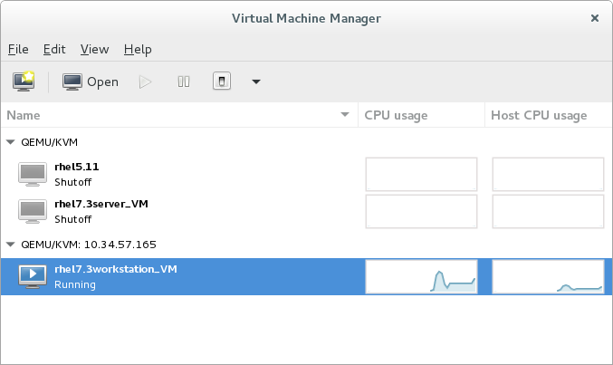
Figure 15.5. Migrated guest virtual machine running in the destination host physical machine
Chapter 16. Guest Virtual Machine Device Configuration
- Emulated devices are purely virtual devices that mimic real hardware, allowing unmodified guest operating systems to work with them using their standard in-box drivers.
- Virtio devices (also known as paravirtualized) are purely virtual devices designed to work optimally in a virtual machine. Virtio devices are similar to emulated devices, but non-Linux virtual machines do not include the drivers they require by default. Virtualization management software like the Virtual Machine Manager (virt-manager) and the Red Hat Virtualization Hypervisor install these drivers automatically for supported non-Linux guest operating systems. Red Hat Enterprise Linux 7 supports up to 216 virtio devices. For more information, see Chapter 5, KVM Paravirtualized (virtio) Drivers.
- Assigned devices are physical devices that are exposed to the virtual machine. This method is also known as passthrough. Device assignment allows virtual machines exclusive access to PCI devices for a range of tasks, and allows PCI devices to appear and behave as if they were physically attached to the guest operating system. Red Hat Enterprise Linux 7 supports up to 32 assigned devices per virtual machine.Device assignment is supported on PCIe devices, including select graphics devices. Parallel PCI devices may be supported as assigned devices, but they have severe limitations due to security and system configuration conflicts.
Note
allow_unsafe_interrupts option to the vfio_iommu_type1 module. This may either be done persistently by adding a .conf file (for example local.conf) to /etc/modprobe.d containing the following:
options vfio_iommu_type1 allow_unsafe_interrupts=1or dynamically using the sysfs entry to do the same:
# echo 1 > /sys/module/vfio_iommu_type1/parameters/allow_unsafe_interrupts
16.1. PCI Devices
Procedure 16.1. Preparing an Intel system for PCI device assignment
Enable the Intel VT-d specifications
The Intel VT-d specifications provide hardware support for directly assigning a physical device to a virtual machine. These specifications are required to use PCI device assignment with Red Hat Enterprise Linux.The Intel VT-d specifications must be enabled in the BIOS. Some system manufacturers disable these specifications by default. The terms used to see these specifications can differ between manufacturers; consult your system manufacturer's documentation for the appropriate terms.Activate Intel VT-d in the kernel
Activate Intel VT-d in the kernel by adding theintel_iommu=onandiommu=ptparameters to the end of the GRUB_CMDLINX_LINUX line, within the quotes, in the/etc/sysconfig/grubfile.The example below is a modifiedgrubfile with Intel VT-d activated.GRUB_CMDLINE_LINUX="rd.lvm.lv=vg_VolGroup00/LogVol01 vconsole.font=latarcyrheb-sun16 rd.lvm.lv=vg_VolGroup_1/root vconsole.keymap=us $([ -x /usr/sbin/rhcrashkernel-param ] && /usr/sbin/ rhcrashkernel-param || :) rhgb quiet intel_iommu=on iommu=pt"Regenerate config file
Regenerate /etc/grub2.cfg by running:grub2-mkconfig -o /etc/grub2.cfg
Note that if you are using a UEFI-based host, the target file should be/etc/grub2-efi.cfg.Ready to use
Reboot the system to enable the changes. Your system is now capable of PCI device assignment.
Procedure 16.2. Preparing an AMD system for PCI device assignment
Enable the AMD IOMMU specifications
The AMD IOMMU specifications are required to use PCI device assignment in Red Hat Enterprise Linux. These specifications must be enabled in the BIOS. Some system manufacturers disable these specifications by default.Enable IOMMU kernel support
Appendiommu=ptto the end of the GRUB_CMDLINX_LINUX line, within the quotes, in/etc/sysconfig/grubso that AMD IOMMU specifications are enabled at boot.Regenerate config file
Regenerate /etc/grub2.cfg by running:grub2-mkconfig -o /etc/grub2.cfg
Note that if you are using a UEFI-based host, the target file should be/etc/grub2-efi.cfg.Ready to use
Reboot the system to enable the changes. Your system is now capable of PCI device assignment.
Note
16.1.1. Assigning a PCI Device with virsh
pci_0000_01_00_0, and a fully virtualized guest machine named guest1-rhel7-64.
Procedure 16.3. Assigning a PCI device to a guest virtual machine with virsh
Identify the device
First, identify the PCI device designated for device assignment to the virtual machine. Use thelspcicommand to list the available PCI devices. You can refine the output oflspciwithgrep.This example uses the Ethernet controller highlighted in the following output:#
lspci | grep Ethernet00:19.0 Ethernet controller: Intel Corporation 82567LM-2 Gigabit Network Connection 01:00.0 Ethernet controller: Intel Corporation 82576 Gigabit Network Connection (rev 01) 01:00.1 Ethernet controller: Intel Corporation 82576 Gigabit Network Connection (rev 01)This Ethernet controller is shown with the short identifier00:19.0. We need to find out the full identifier used byvirshin order to assign this PCI device to a virtual machine.To do so, use thevirsh nodedev-listcommand to list all devices of a particular type (pci) that are attached to the host machine. Then look at the output for the string that maps to the short identifier of the device you wish to use.This example shows the string that maps to the Ethernet controller with the short identifier00:19.0. Note that the:and.characters are replaced with underscores in the full identifier.#
virsh nodedev-list --cap pcipci_0000_00_00_0 pci_0000_00_01_0 pci_0000_00_03_0 pci_0000_00_07_0 pci_0000_00_10_0 pci_0000_00_10_1 pci_0000_00_14_0 pci_0000_00_14_1 pci_0000_00_14_2 pci_0000_00_14_3 pci_0000_00_19_0 pci_0000_00_1a_0 pci_0000_00_1a_1 pci_0000_00_1a_2 pci_0000_00_1a_7 pci_0000_00_1b_0 pci_0000_00_1c_0 pci_0000_00_1c_1 pci_0000_00_1c_4 pci_0000_00_1d_0 pci_0000_00_1d_1 pci_0000_00_1d_2 pci_0000_00_1d_7 pci_0000_00_1e_0 pci_0000_00_1f_0 pci_0000_00_1f_2 pci_0000_00_1f_3 pci_0000_01_00_0 pci_0000_01_00_1 pci_0000_02_00_0 pci_0000_02_00_1 pci_0000_06_00_0 pci_0000_07_02_0 pci_0000_07_03_0Record the PCI device number that maps to the device you want to use; this is required in other steps.Review device information
Information on the domain, bus, and function are available from output of thevirsh nodedev-dumpxmlcommand:# virsh nodedev-dumpxml pci_0000_00_19_0 <device> <name>pci_0000_00_19_0</name> <parent>computer</parent> <driver> <name>e1000e</name> </driver> <capability type='pci'> <domain>0</domain> <bus>0</bus> <slot>25</slot> <function>0</function> <product id='0x1502'>82579LM Gigabit Network Connection</product> <vendor id='0x8086'>Intel Corporation</vendor> <iommuGroup number='7'> <address domain='0x0000' bus='0x00' slot='0x19' function='0x0'/> </iommuGroup> </capability> </device>Figure 16.1. Dump contents
Note
An IOMMU group is determined based on the visibility and isolation of devices from the perspective of the IOMMU. Each IOMMU group may contain one or more devices. When multiple devices are present, all endpoints within the IOMMU group must be claimed for any device within the group to be assigned to a guest. This can be accomplished either by also assigning the extra endpoints to the guest or by detaching them from the host driver usingvirsh nodedev-detach. Devices contained within a single group may not be split between multiple guests or split between host and guest. Non-endpoint devices such as PCIe root ports, switch ports, and bridges should not be detached from the host drivers and will not interfere with assignment of endpoints.Devices within an IOMMU group can be determined using the iommuGroup section of thevirsh nodedev-dumpxmloutput. Each member of the group is provided in a separate "address" field. This information may also be found in sysfs using the following:$
An example of the output from this would be:ls /sys/bus/pci/devices/0000:01:00.0/iommu_group/devices/0000:01:00.0 0000:01:00.1
To assign only 0000.01.00.0 to the guest, the unused endpoint should be detached from the host before starting the guest:$
virsh nodedev-detach pci_0000_01_00_1Determine required configuration details
See the output from thevirsh nodedev-dumpxml pci_0000_00_19_0command for the values required for the configuration file.The example device has the following values: bus = 0, slot = 25 and function = 0. The decimal configuration uses those three values:bus='0' slot='25' function='0'
Add configuration details
Runvirsh edit, specifying the virtual machine name, and add a device entry in the<devices>section to assign the PCI device to the guest virtual machine. For example:#
virsh edit guest1-rhel7-64<devices> [...] <hostdev mode='subsystem' type='pci' managed='yes'> <source> <address domain='0' bus='0' slot='25' function='0'/> </source> </hostdev> [...] </devices>Figure 16.2. Add PCI device
Alternately, runvirsh attach-device, specifying the virtual machine name and the guest's XML file:virsh attach-device guest1-rhel7-64
file.xmlNote
PCI devices may include an optional read-only memory (ROM) module, also known as an option ROM or expansion ROM, for delivering device firmware or pre-boot drivers (such as PXE) for the device. Generally, these option ROMs also work in a virtualized environment when using PCI device assignment to attach a physical PCI device to a VM.However, in some cases, the option ROM can be unnecessary, which may cause the VM to boot more slowly, or the pre-boot driver delivered by the device can be incompatible with virtualization, which may cause the guest OS boot to fail. In such cases, Red Hat recommends masking the option ROM from the VM. To do so:- On the host, verify that the device to assign has an expansion ROM base address register (BAR). To do so, use the
lspci -vcommand for the device, and check the output for a line that includes the following:Expansion ROM at
- Add the <rom bar='off'/> element as a child of the <hostdev> element in the guest's XML configuration:
<hostdev mode='subsystem' type='pci' managed='yes'> <source> <address domain='0' bus='0' slot='25' function='0'/> </source> <rom bar='off'/> </hostdev>
Start the virtual machine
#
virsh start guest1-rhel7-64
16.1.2. Assigning a PCI Device with virt-manager
virt-manager tool. The following procedure adds a Gigabit Ethernet controller to a guest virtual machine.
Procedure 16.4. Assigning a PCI device to a guest virtual machine using virt-manager
Open the hardware settings
Open the guest virtual machine and click the button to add a new device to the virtual machine.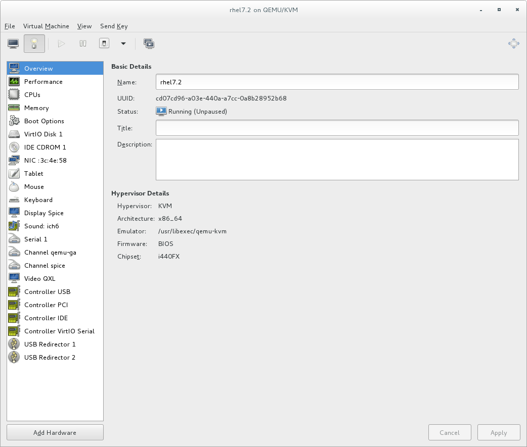
Figure 16.3. The virtual machine hardware information window
Select a PCI device
Select PCI Host Device from the Hardware list on the left.Select an unused PCI device. Note that selecting PCI devices presently in use by another guest causes errors. In this example, a spare audio controller is used. Click Finish to complete setup.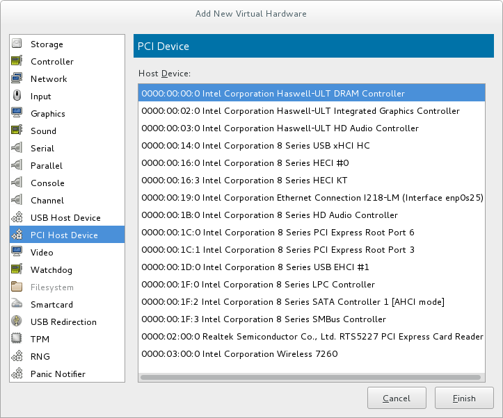
Figure 16.4. The Add new virtual hardware wizard
Add the new device
The setup is complete and the guest virtual machine now has direct access to the PCI device.
Figure 16.5. The virtual machine hardware information window
Note
16.1.3. PCI Device Assignment with virt-install
--host-device parameter.
Procedure 16.5. Assigning a PCI device to a virtual machine with virt-install
Identify the device
Identify the PCI device designated for device assignment to the guest virtual machine.#
lspci | grep Ethernet00:19.0 Ethernet controller: Intel Corporation 82567LM-2 Gigabit Network Connection 01:00.0 Ethernet controller: Intel Corporation 82576 Gigabit Network Connection (rev 01) 01:00.1 Ethernet controller: Intel Corporation 82576 Gigabit Network Connection (rev 01)Thevirsh nodedev-listcommand lists all devices attached to the system, and identifies each PCI device with a string. To limit output to only PCI devices, enter the following command:#
virsh nodedev-list --cap pcipci_0000_00_00_0 pci_0000_00_01_0 pci_0000_00_03_0 pci_0000_00_07_0 pci_0000_00_10_0 pci_0000_00_10_1 pci_0000_00_14_0 pci_0000_00_14_1 pci_0000_00_14_2 pci_0000_00_14_3 pci_0000_00_19_0 pci_0000_00_1a_0 pci_0000_00_1a_1 pci_0000_00_1a_2 pci_0000_00_1a_7 pci_0000_00_1b_0 pci_0000_00_1c_0 pci_0000_00_1c_1 pci_0000_00_1c_4 pci_0000_00_1d_0 pci_0000_00_1d_1 pci_0000_00_1d_2 pci_0000_00_1d_7 pci_0000_00_1e_0 pci_0000_00_1f_0 pci_0000_00_1f_2 pci_0000_00_1f_3 pci_0000_01_00_0 pci_0000_01_00_1 pci_0000_02_00_0 pci_0000_02_00_1 pci_0000_06_00_0 pci_0000_07_02_0 pci_0000_07_03_0Record the PCI device number; the number is needed in other steps.Information on the domain, bus and function are available from output of thevirsh nodedev-dumpxmlcommand:#
virsh nodedev-dumpxml pci_0000_01_00_0<device> <name>pci_0000_01_00_0</name> <parent>pci_0000_00_01_0</parent> <driver> <name>igb</name> </driver> <capability type='pci'> <domain>0</domain> <bus>1</bus> <slot>0</slot> <function>0</function> <product id='0x10c9'>82576 Gigabit Network Connection</product> <vendor id='0x8086'>Intel Corporation</vendor> <iommuGroup number='7'> <address domain='0x0000' bus='0x00' slot='0x19' function='0x0'/> </iommuGroup> </capability> </device>Figure 16.6. PCI device file contents
Note
If there are multiple endpoints in the IOMMU group and not all of them are assigned to the guest, you will need to manually detach the other endpoint(s) from the host by running the following command before you start the guest:$
virsh nodedev-detach pci_0000_00_19_1See the Note in Section 16.1.1, “Assigning a PCI Device with virsh” for more information on IOMMU groups.Add the device
Use the PCI identifier output from thevirsh nodedevcommand as the value for the--host-deviceparameter.virt-install \ --name=guest1-rhel7-64 \ --disk path=/var/lib/libvirt/images/guest1-rhel7-64.img,size=8 \ --vcpus=2 --ram=2048 \ --location=http://example1.com/installation_tree/RHEL7.0-Server-x86_64/os \ --nonetworks \ --os-type=linux \ --os-variant=rhel7 --host-device=pci_0000_01_00_0Complete the installation
Complete the guest installation. The PCI device should be attached to the guest.
16.1.4. Detaching an Assigned PCI Device
managed mode (configured using the managed='yes' parameter in the domain XML file), it attaches to the guest machine and detaches from the guest machine and re-attaches to the host machine as necessary. If the PCI device is not in managed mode, you can detach the PCI device from the guest machine and re-attach it using virsh or virt-manager.
Procedure 16.6. Detaching a PCI device from a guest with virsh
Detach the device
Use the following command to detach the PCI device from the guest by removing it in the guest's XML file:#
virsh detach-device name_of_guest file.xmlRe-attach the device to the host (optional)
If the device is inmanagedmode, skip this step. The device will be returned to the host automatically.If the device is not usingmanagedmode, use the following command to re-attach the PCI device to the host machine:#
virsh nodedev-reattach deviceFor example, to re-attach thepci_0000_01_00_0device to the host:#
virsh nodedev-reattach pci_0000_01_00_0The device is now available for host use.
Procedure 16.7. Detaching a PCI Device from a guest with virt-manager
Open the virtual hardware details screen
In virt-manager, double-click the virtual machine that contains the device. Select the Show virtual hardware details button to display a list of virtual hardware.
Figure 16.7. The virtual hardware details button
Select and remove the device
Select the PCI device to be detached from the list of virtual devices in the left panel.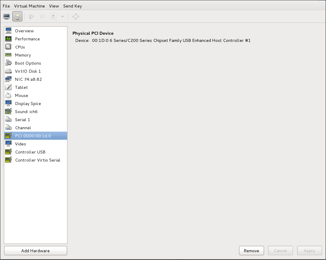
Figure 16.8. Selecting the PCI device to be detached
Click the button to confirm. The device is now available for host use.
16.1.5. PCI Bridges
16.1.6. PCI Device Assignment Restrictions
allow_unsafe_interrupts option to the vfio_iommu_type1 module. This may either be done persistently by adding a .conf file (for example local.conf) to /etc/modprobe.d containing the following:
options vfio_iommu_type1 allow_unsafe_interrupts=1or dynamically using the sysfs entry to do the same:
# echo 1 > /sys/module/vfio_iommu_type1/parameters/allow_unsafe_interrupts
16.2. PCI Device Assignment with SR-IOV Devices
<source> element) can be directly connected to the guest using direct device assignment (sometimes referred to as passthrough). Due to limitations in standard single-port PCI ethernet card driver design, only Single Root I/O Virtualization (SR-IOV) virtual function (VF) devices can be assigned in this manner; to assign a standard single-port PCI or PCIe Ethernet card to a guest, use the traditional <hostdev> device definition.
<devices>
<interface type='hostdev'>
<driver name='vfio'/>
<source>
<address type='pci' domain='0x0000' bus='0x00' slot='0x07' function='0x0'/>
</source>
<mac address='52:54:00:6d:90:02'>
<virtualport type='802.1Qbh'>
<parameters profileid='finance'/>
</virtualport>
</interface>
</devices>Figure 16.9. XML example for PCI device assignment
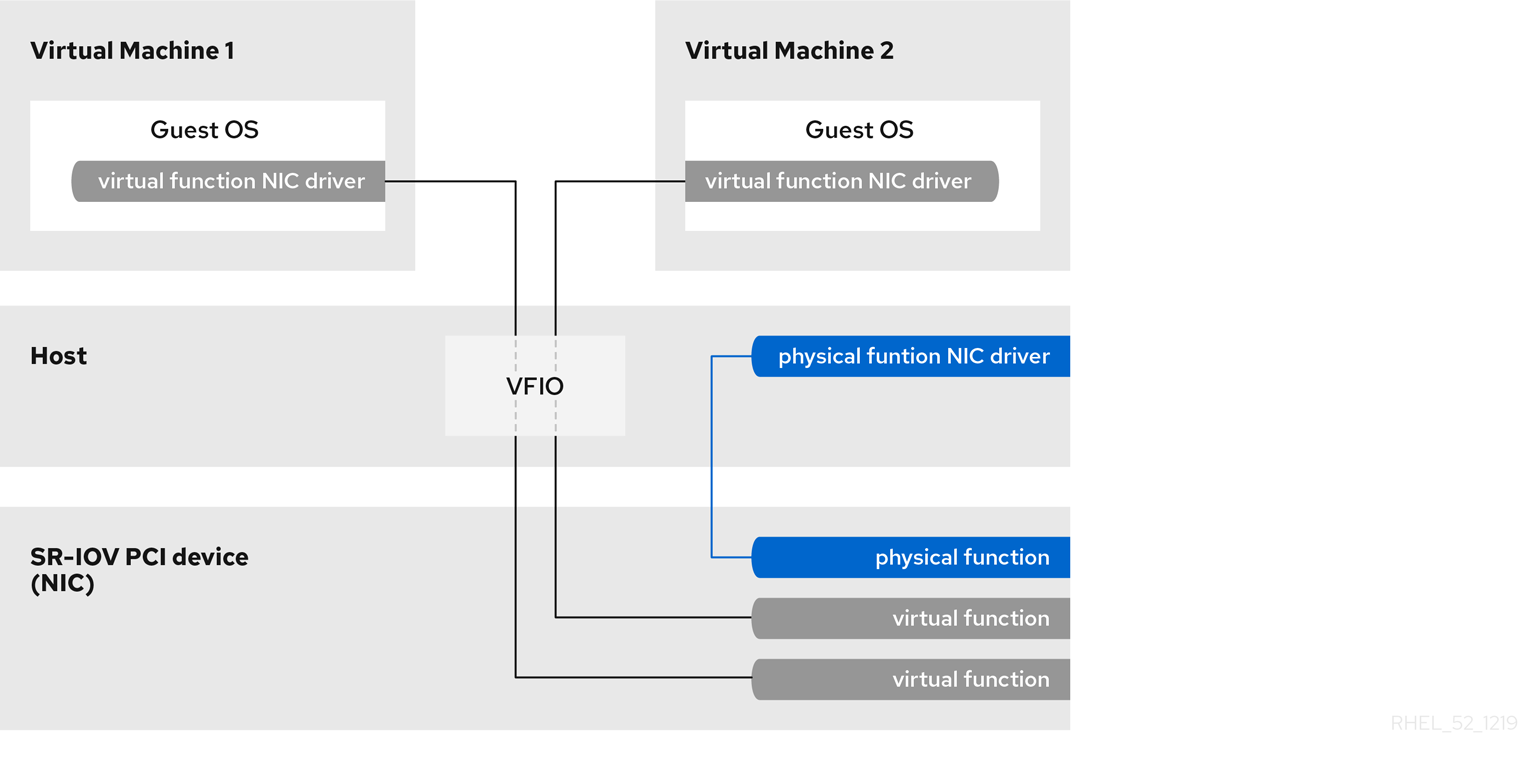
Figure 16.10. How SR-IOV works
- Physical Functions (PFs) are full PCIe devices that include the SR-IOV capabilities. Physical Functions are discovered, managed, and configured as normal PCI devices. Physical Functions configure and manage the SR-IOV functionality by assigning Virtual Functions.
- Virtual Functions (VFs) are simple PCIe functions that only process I/O. Each Virtual Function is derived from a Physical Function. The number of Virtual Functions a device may have is limited by the device hardware. A single Ethernet port, the Physical Device, may map to many Virtual Functions that can be shared to virtual machines.
16.2.1. Advantages of SR-IOV
16.2.2. Using SR-IOV
<hostdev> with the virsh edit or virsh attach-device command. However, this can be problematic because unlike a regular network device, an SR-IOV VF network device does not have a permanent unique MAC address, and is assigned a new MAC address each time the host is rebooted. Because of this, even if the guest is assigned the same VF after a reboot, when the host is rebooted the guest determines its network adapter to have a new MAC address. As a result, the guest believes there is new hardware connected each time, and will usually require re-configuration of the guest's network settings.
<interface type='hostdev'> interface device. Using this interface device, libvirt will first perform any network-specific hardware/switch initialization indicated (such as setting the MAC address, VLAN tag, or 802.1Qbh virtualport parameters), then perform the PCI device assignment to the guest.
<interface type='hostdev'> interface device requires:
- an SR-IOV-capable network card,
- host hardware that supports either the Intel VT-d or the AMD IOMMU extensions
- the PCI address of the VF to be assigned.
Important
Procedure 16.8. Attach an SR-IOV network device on an Intel or AMD system
Enable Intel VT-d or the AMD IOMMU specifications in the BIOS and kernel
On an Intel system, enable Intel VT-d in the BIOS if it is not enabled already. See Procedure 16.1, “Preparing an Intel system for PCI device assignment” for procedural help on enabling Intel VT-d in the BIOS and kernel.Skip this step if Intel VT-d is already enabled and working.On an AMD system, enable the AMD IOMMU specifications in the BIOS if they are not enabled already. See Procedure 16.2, “Preparing an AMD system for PCI device assignment” for procedural help on enabling IOMMU in the BIOS.Verify support
Verify if the PCI device with SR-IOV capabilities is detected. This example lists an Intel 82576 network interface card which supports SR-IOV. Use thelspcicommand to verify whether the device was detected.#
lspci03:00.0 Ethernet controller: Intel Corporation 82576 Gigabit Network Connection (rev 01) 03:00.1 Ethernet controller: Intel Corporation 82576 Gigabit Network Connection (rev 01)Note that the output has been modified to remove all other devices.Activate Virtual Functions
Run the following command:#
echo ${num_vfs} > /sys/class/net/enp14s0f0/device/sriov_numvfsMake the Virtual Functions persistent
To make the Virtual Functions persistent across reboots, use the editor of your choice to create an udev rule similar to the following, where you specify the intended number of VFs (in this example,2), up to the limit supported by the network interface card. In the following example, replace enp14s0f0 with the PF network device name(s) and adjust the value ofENV{ID_NET_DRIVER}to match the driver in use:#
vim /etc/udev/rules.d/enp14s0f0.rulesACTION=="add", SUBSYSTEM=="net", ENV{ID_NET_DRIVER}=="ixgbe", ATTR{device/sriov_numvfs}="2"This will ensure the feature is enabled at boot-time.Inspect the new Virtual Functions
Using thelspcicommand, list the newly added Virtual Functions attached to the Intel 82576 network device. (Alternatively, usegrepto search forVirtual Function, to search for devices that support Virtual Functions.)#
lspci | grep 825760b:00.0 Ethernet controller: Intel Corporation 82576 Gigabit Network Connection (rev 01) 0b:00.1 Ethernet controller: Intel Corporation 82576 Gigabit Network Connection (rev 01) 0b:10.0 Ethernet controller: Intel Corporation 82576 Virtual Function (rev 01) 0b:10.1 Ethernet controller: Intel Corporation 82576 Virtual Function (rev 01) 0b:10.2 Ethernet controller: Intel Corporation 82576 Virtual Function (rev 01) 0b:10.3 Ethernet controller: Intel Corporation 82576 Virtual Function (rev 01) 0b:10.4 Ethernet controller: Intel Corporation 82576 Virtual Function (rev 01) 0b:10.5 Ethernet controller: Intel Corporation 82576 Virtual Function (rev 01) 0b:10.6 Ethernet controller: Intel Corporation 82576 Virtual Function (rev 01) 0b:10.7 Ethernet controller: Intel Corporation 82576 Virtual Function (rev 01) 0b:11.0 Ethernet controller: Intel Corporation 82576 Virtual Function (rev 01) 0b:11.1 Ethernet controller: Intel Corporation 82576 Virtual Function (rev 01) 0b:11.2 Ethernet controller: Intel Corporation 82576 Virtual Function (rev 01) 0b:11.3 Ethernet controller: Intel Corporation 82576 Virtual Function (rev 01) 0b:11.4 Ethernet controller: Intel Corporation 82576 Virtual Function (rev 01) 0b:11.5 Ethernet controller: Intel Corporation 82576 Virtual Function (rev 01)The identifier for the PCI device is found with the-nparameter of thelspcicommand. The Physical Functions correspond to0b:00.0and0b:00.1. All Virtual Functions haveVirtual Functionin the description.Verify devices exist with virsh
Thelibvirtservice must recognize the device before adding a device to a virtual machine.libvirtuses a similar notation to thelspcioutput. All punctuation characters, : and ., inlspcioutput are changed to underscores (_).Use thevirsh nodedev-listcommand and thegrepcommand to filter the Intel 82576 network device from the list of available host devices.0bis the filter for the Intel 82576 network devices in this example. This may vary for your system and may result in additional devices.#
virsh nodedev-list | greppci_0000_0b_00_0 pci_0000_0b_00_1 pci_0000_0b_10_0 pci_0000_0b_10_1 pci_0000_0b_10_2 pci_0000_0b_10_3 pci_0000_0b_10_4 pci_0000_0b_10_5 pci_0000_0b_10_6 pci_0000_0b_11_7 pci_0000_0b_11_1 pci_0000_0b_11_2 pci_0000_0b_11_3 pci_0000_0b_11_4 pci_0000_0b_11_50bThe PCI addresses for the Virtual Functions and Physical Functions should be in the list.Get device details with virsh
Thepci_0000_0b_00_0is one of the Physical Functions andpci_0000_0b_10_0is the first corresponding Virtual Function for that Physical Function. Use thevirsh nodedev-dumpxmlcommand to get device details for both devices.# virsh nodedev-dumpxml pci_0000_03_00_0 <device> <name>pci_0000_03_00_0</name> <path>/sys/devices/pci0000:00/0000:00:01.0/0000:03:00.0</path> <parent>pci_0000_00_01_0</parent> <driver> <name>igb</name> </driver> <capability type='pci'> <domain>0</domain> <bus>3</bus> <slot>0</slot> <function>0</function> <product id='0x10c9'>82576 Gigabit Network Connection</product> <vendor id='0x8086'>Intel Corporation</vendor> <capability type='virt_functions'> <address domain='0x0000' bus='0x03' slot='0x10' function='0x0'/> <address domain='0x0000' bus='0x03' slot='0x10' function='0x2'/> <address domain='0x0000' bus='0x03' slot='0x10' function='0x4'/> <address domain='0x0000' bus='0x03' slot='0x10' function='0x6'/> <address domain='0x0000' bus='0x03' slot='0x11' function='0x0'/> <address domain='0x0000' bus='0x03' slot='0x11' function='0x2'/> <address domain='0x0000' bus='0x03' slot='0x11' function='0x4'/> </capability> <iommuGroup number='14'> <address domain='0x0000' bus='0x03' slot='0x00' function='0x0'/> <address domain='0x0000' bus='0x03' slot='0x00' function='0x1'/> </iommuGroup> </capability> </device># virsh nodedev-dumpxml pci_0000_03_11_5 <device> <name>pci_0000_03_11_5</name> <path>/sys/devices/pci0000:00/0000:00:01.0/0000:03:11.5</path> <parent>pci_0000_00_01_0</parent> <driver> <name>igbvf</name> </driver> <capability type='pci'> <domain>0</domain> <bus>3</bus> <slot>17</slot> <function>5</function> <product id='0x10ca'>82576 Virtual Function</product> <vendor id='0x8086'>Intel Corporation</vendor> <capability type='phys_function'> <address domain='0x0000' bus='0x03' slot='0x00' function='0x1'/> </capability> <iommuGroup number='35'> <address domain='0x0000' bus='0x03' slot='0x11' function='0x5'/> </iommuGroup> </capability> </device>This example adds the Virtual Functionpci_0000_03_10_2to the virtual machine in Step 8. Note thebus,slotandfunctionparameters of the Virtual Function: these are required for adding the device.Copy these parameters into a temporary XML file, such as/tmp/new-interface.xmlfor example.<interface type='hostdev' managed='yes'> <source> <address type='pci' domain='0x0000' bus='0x03' slot='0x10' function='0x2'/> </source> </interface>Note
When the virtual machine starts, it should see a network device of the type provided by the physical adapter, with the configured MAC address. This MAC address will remain unchanged across host and guest reboots.The following<interface>example shows the syntax for the optional<mac address>,<virtualport>, and<vlan>elements. In practice, use either the<vlan>or<virtualport>element, not both simultaneously as shown in the example:... <devices> ... <interface type='hostdev' managed='yes'> <source> <address type='pci' domain='0' bus='11' slot='16' function='0'/> </source> <mac address='52:54:00:6d:90:02'> <vlan> <tag id='42'/> </vlan> <virtualport type='802.1Qbh'> <parameters profileid='finance'/> </virtualport> </interface> ... </devices>If you do not specify a MAC address, one will be automatically generated. The<virtualport>element is only used when connecting to an 802.11Qbh hardware switch. The<vlan>element will transparently put the guest's device on the VLAN tagged42.Add the Virtual Function to the virtual machine
Add the Virtual Function to the virtual machine using the following command with the temporary file created in the previous step. This attaches the new device immediately and saves it for subsequent guest restarts.virsh attach-device MyGuest
/tmp/new-interface.xml--live --configSpecifying the--liveoption withvirsh attach-deviceattaches the new device to the running guest. Using the--configoption ensures the new device is available after future guest restarts.Note
The--liveoption is only accepted when the guest is running.virshwill return an error if the--liveoption is used on a non-running guest.
16.2.3. Configuring PCI Assignment with SR-IOV Devices
<hostdev> element. However, SR-IOV VF network devices do not have permanent unique MAC addresses, which causes problems where the guest virtual machine's network settings need to be re-configured each time the host physical machine is rebooted. To fix this, you need to set the MAC address prior to assigning the VF to the host physical machine after every boot of the guest virtual machine. In order to assign this MAC address, as well as other options, see the following procedure:
Procedure 16.9. Configuring MAC addresses, vLAN, and virtual ports for assigning PCI devices on SR-IOV
<hostdev> element cannot be used for function-specific items like MAC address assignment, vLAN tag ID assignment, or virtual port assignment, because the <mac>, <vlan>, and <virtualport> elements are not valid children for <hostdev>. Instead, these elements can be used with the hostdev interface type: <interface type='hostdev'>. This device type behaves as a hybrid of an <interface> and <hostdev>. Thus, before assigning the PCI device to the guest virtual machine, libvirt initializes the network-specific hardware/switch that is indicated (such as setting the MAC address, setting a vLAN tag, or associating with an 802.1Qbh switch) in the guest virtual machine's XML configuration file. For information on setting the vLAN tag, see Section 17.16, “Setting vLAN Tags”.
Gather information
In order to use<interface type='hostdev'>, you must have an SR-IOV-capable network card, host physical machine hardware that supports either the Intel VT-d or AMD IOMMU extensions, and you must know the PCI address of the VF that you wish to assign.Shut down the guest virtual machine
Usingvirsh shutdowncommand, shut down the guest virtual machine (here named guestVM).#
virsh shutdown guestVMOpen the XML file for editing
#
virsh edit guestVM.xmlOptional: For the XML configuration file that was created by thevirsh savecommand, run:#
virsh save-image-edit guestVM.xml--runningThe configuration file, in this example guestVM.xml, opens in your default editor. For more information, see Section 20.7.5, “Editing the Guest Virtual Machine Configuration”Edit the XML file
Update the configuration file (guestVM.xml) to have a<devices>entry similar to the following:<devices> ... <interface type='hostdev' managed='yes'> <source> <address type='pci' domain='0x0' bus='0x00' slot='0x07' function='0x0'/> <!--these values can be decimal as well--> </source> <mac address='52:54:00:6d:90:02'/> <!--sets the mac address--> <virtualport type='802.1Qbh'> <!--sets the virtual port for the 802.1Qbh switch--> <parameters profileid='finance'/> </virtualport> <vlan> <!--sets the vlan tag--> <tag id='42'/> </vlan> </interface> ... </devices>Figure 16.11. Sample domain XML for hostdev interface type
Note
If you do not provide a MAC address, one will be automatically generated, just as with any other type of interface device. In addition, the<virtualport>element is only used if you are connecting to an 802.11Qgh hardware switch. 802.11Qbg (also known as "VEPA") switches are currently not supported.Restart the guest virtual machine
Run thevirsh startcommand to restart the guest virtual machine you shut down in step 2. See Section 20.6, “Starting, Resuming, and Restoring a Virtual Machine” for more information.#
virsh start guestVMWhen the guest virtual machine starts, it sees the network device provided to it by the physical host machine's adapter, with the configured MAC address. This MAC address remains unchanged across guest virtual machine and host physical machine reboots.
16.2.4. Setting PCI device assignment from a pool of SR-IOV virtual functions
- The specified VF must be available any time the guest virtual machine is started. Therefore, the administrator must permanently assign each VF to a single guest virtual machine (or modify the configuration file for every guest virtual machine to specify a currently unused VF's PCI address each time every guest virtual machine is started).
- If the guest virtual machine is moved to another host physical machine, that host physical machine must have exactly the same hardware in the same location on the PCI bus (or the guest virtual machine configuration must be modified prior to start).
Procedure 16.10. Creating a device pool
Shut down the guest virtual machine
Usingvirsh shutdowncommand, shut down the guest virtual machine, here named guestVM.#
virsh shutdown guestVMCreate a configuration file
Using your editor of choice, create an XML file (named passthrough.xml, for example) in the/tmpdirectory. Make sure to replacepf dev='eth3'with the netdev name of your own SR-IOV device's Physical Function (PF).The following is an example network definition that will make available a pool of all VFs for the SR-IOV adapter with its PF at "eth3' on the host physical machine:<network> <name>passthrough</name> <!-- This is the name of the file you created --> <forward mode='hostdev' managed='yes'> <pf dev='myNetDevName'/> <!-- Use the netdev name of your SR-IOV devices PF here --> </forward> </network>Figure 16.12. Sample network definition domain XML
Load the new XML file
Enter the following command, replacing /tmp/passthrough.xml with the name and location of your XML file you created in the previous step:#
virsh net-define /tmp/passthrough.xmlRestarting the guest
Run the following, replacing passthrough.xml with the name of your XML file you created in the previous step:#
virsh net-autostart passthrough#virsh net-start passthroughRe-start the guest virtual machine
Run thevirsh startcommand to restart the guest virtual machine you shutdown in the first step (example uses guestVM as the guest virtual machine's domain name). See Section 20.6, “Starting, Resuming, and Restoring a Virtual Machine” for more information.#
virsh start guestVMInitiating passthrough for devices
Although only a single device is shown, libvirt will automatically derive the list of all VFs associated with that PF the first time a guest virtual machine is started with an interface definition in its domain XML like the following:<interface type='network'> <source network='passthrough'> </interface>Figure 16.13. Sample domain XML for interface network definition
Verification
You can verify this by runningvirsh net-dumpxml passthroughcommand after starting the first guest that uses the network; you will get output similar to the following:<network connections='1'> <name>passthrough</name> <uuid>a6b49429-d353-d7ad-3185-4451cc786437</uuid> <forward mode='hostdev' managed='yes'> <pf dev='eth3'/> <address type='pci' domain='0x0000' bus='0x02' slot='0x10' function='0x1'/> <address type='pci' domain='0x0000' bus='0x02' slot='0x10' function='0x3'/> <address type='pci' domain='0x0000' bus='0x02' slot='0x10' function='0x5'/> <address type='pci' domain='0x0000' bus='0x02' slot='0x10' function='0x7'/> <address type='pci' domain='0x0000' bus='0x02' slot='0x11' function='0x1'/> <address type='pci' domain='0x0000' bus='0x02' slot='0x11' function='0x3'/> <address type='pci' domain='0x0000' bus='0x02' slot='0x11' function='0x5'/> </forward> </network>Figure 16.14. XML dump file passthrough contents
16.2.5. SR-IOV Restrictions
- Intel® 82576NS Gigabit Ethernet Controller (
igbdriver) - Intel® 82576EB Gigabit Ethernet Controller (
igbdriver) - Intel® 82599ES 10 Gigabit Ethernet Controller (
ixgbedriver) - Intel® 82599EB 10 Gigabit Ethernet Controller (
ixgbedriver)
16.3. USB Devices
16.3.1. Assigning USB Devices to Guest Virtual Machines
- Using USB passthrough - this requires the device to be physically connected to the host physical machine that is hosting the guest virtual machine. SPICE is not needed in this case. USB devices on the host can be passed to the guest in the command line or virt-manager. See Section 19.3.2, “Attaching USB Devices to a Guest Virtual Machine” for virt manager directions. Note that the virt-manager directions are not suitable for hot plugging or hot unplugging devices. If you want to hot plug/or hot unplug a USB device, see Procedure 20.4, “Hot plugging USB devices for use by the guest virtual machine”.
- Using USB re-direction - USB re-direction is best used in cases where there is a host physical machine that is running in a data center. The user connects to his/her guest virtual machine from a local machine or thin client. On this local machine there is a SPICE client. The user can attach any USB device to the thin client and the SPICE client will redirect the device to the host physical machine on the data center so it can be used by the guest virtual machine that is running on the thin client. For instructions via the virt-manager see Section 19.3.3, “USB Redirection”.
16.3.2. Setting a Limit on USB Device Redirection
-device usb-redir. The filter property takes a string consisting of filter rules, the format for a rule is:
<class>:<vendor>:<product>:<version>:<allow>-1 to designate it to accept any value for a particular field. You may use multiple rules on the same command line using | as a separator. Note that if a device matches none of the passed in rules, redirecting it will not be allowed!
Example 16.1. An example of limiting redirection with a guest virtual machine
- Prepare a guest virtual machine.
- Add the following code excerpt to the guest virtual machine's' domain XML file:
<redirdev bus='usb' type='spicevmc'> <alias name='redir0'/> <address type='usb' bus='0' port='3'/> </redirdev> <redirfilter> <usbdev class='0x08' vendor='0x1234' product='0xBEEF' version='2.0' allow='yes'/> <usbdev class='-1' vendor='-1' product='-1' version='-1' allow='no'/> </redirfilter> - Start the guest virtual machine and confirm the setting changes by running the following:
#
ps -ef | grep $guest_name-device usb-redir,chardev=charredir0,id=redir0,/filter=0x08:0x1234:0xBEEF:0x0200:1|-1:-1:-1:-1:0,bus=usb.0,port=3 - Plug a USB device into a host physical machine, and use virt-manager to connect to the guest virtual machine.
- Click in the menu, which will produce the following message: "Some USB devices are blocked by host policy". Click to confirm and continue.The filter takes effect.
- To make sure that the filter captures properly check the USB device vendor and product, then make the following changes in the host physical machine's domain XML to allow for USB redirection.
<redirfilter> <usbdev class='0x08' vendor='0x0951' product='0x1625' version='2.0' allow='yes'/> <usbdev allow='no'/> </redirfilter> - Restart the guest virtual machine, then use virt-viewer to connect to the guest virtual machine. The USB device will now redirect traffic to the guest virtual machine.
16.4. Configuring Device Controllers
...
<devices>
<controller type='ide' index='0'/>
<controller type='virtio-serial' index='0' ports='16' vectors='4'/>
<controller type='virtio-serial' index='1'>
<address type='pci' domain='0x0000' bus='0x00' slot='0x0a' function='0x0'/>
</controller>
...
</devices>
...
Figure 16.15. Domain XML example for virtual controllers
<controller type>, which must be one of:
- ide
- fdc
- scsi
- sata
- usb
- ccid
- virtio-serial
- pci
<controller> element has a mandatory attribute <controller index> which is the decimal integer describing in which order the bus controller is encountered (for use in controller attributes of <address> elements). When <controller type ='virtio-serial'> there are two additional optional attributes (named ports and vectors), which control how many devices can be connected through the controller.
<controller type ='scsi'>, there is an optional attribute model model, which can have the following values:
- auto
- buslogic
- ibmvscsi
- lsilogic
- lsisas1068
- lsisas1078
- virtio-scsi
- vmpvscsi
<controller type ='usb'>, there is an optional attribute model model, which can have the following values:
- piix3-uhci
- piix4-uhci
- ehci
- ich9-ehci1
- ich9-uhci1
- ich9-uhci2
- ich9-uhci3
- vt82c686b-uhci
- pci-ohci
- nec-xhci
<model='none'> may be used. .
<address> can specify the exact relationship of the controller to its master bus, with semantics as shown in Section 16.5, “Setting Addresses for Devices”.
<driver> can specify the driver-specific options. Currently, it only supports attribute queues, which specifies the number of queues for the controller. For best performance, it is recommended to specify a value matching the number of vCPUs.
<master> to specify the exact relationship of the companion to its master controller. A companion controller is on the same bus as its master, so the companion index value should be equal.
...
<devices>
<controller type='usb' index='0' model='ich9-ehci1'>
<address type='pci' domain='0' bus='0' slot='4' function='7'/>
</controller>
<controller type='usb' index='0' model='ich9-uhci1'>
<master startport='0'/>
<address type='pci' domain='0' bus='0' slot='4' function='0' multifunction='on'/>
</controller>
...
</devices>
...
Figure 16.16. Domain XML example for USB controllers
model attribute with the following possible values:
- pci-root
- pcie-root
- pci-bridge
- dmi-to-pci-bridge
index='0' is auto-added and required to use PCI devices. pci-root has no address. PCI bridges are auto-added if there are too many devices to fit on the one bus provided by model='pci-root', or a PCI bus number greater than zero was specified. PCI bridges can also be specified manually, but their addresses should only see PCI buses provided by already specified PCI controllers. Leaving gaps in the PCI controller indexes might lead to an invalid configuration. The following XML example can be added to the <devices> section:
...
<devices>
<controller type='pci' index='0' model='pci-root'/>
<controller type='pci' index='1' model='pci-bridge'>
<address type='pci' domain='0' bus='0' slot='5' function='0' multifunction='off'/>
</controller>
</devices>
...
Figure 16.17. Domain XML example for PCI bridge
index='0' is auto-added to the domain's configuration. pcie-root has also no address, but provides 31 slots (numbered 1-31) and can only be used to attach PCIe devices. In order to connect standard PCI devices on a system which has a pcie-root controller, a pci controller with model='dmi-to-pci-bridge' is automatically added. A dmi-to-pci-bridge controller plugs into a PCIe slot (as provided by pcie-root), and itself provides 31 standard PCI slots (which are not hot-pluggable). In order to have hot-pluggable PCI slots in the guest system, a pci-bridge controller will also be automatically created and connected to one of the slots of the auto-created dmi-to-pci-bridge controller; all guest devices with PCI addresses that are auto-determined by libvirt will be placed on this pci-bridge device.
...
<devices>
<controller type='pci' index='0' model='pcie-root'/>
<controller type='pci' index='1' model='dmi-to-pci-bridge'>
<address type='pci' domain='0' bus='0' slot='0xe' function='0'/>
</controller>
<controller type='pci' index='2' model='pci-bridge'>
<address type='pci' domain='0' bus='1' slot='1' function='0'/>
</controller>
</devices>
...
Figure 16.18. Domain XML example for PCIe (PCI express)
...
<devices>
<controller type='usb' index='3' model='nec-xhci'>
<address type='pci' domain='0x0000' bus='0x00' slot='0x0f' function='0x0'/>
</controller>
</devices>
...
Figure 16.19. Domain XML example for USB3/xHCI devices
16.5. Setting Addresses for Devices
<address> sub-element which is used to describe where the device is placed on the virtual bus presented to the guest virtual machine. If an address (or any optional attribute within an address) is omitted on input, libvirt will generate an appropriate address; but an explicit address is required if more control over layout is required. For domain XML device examples that include an <address> element, see Figure 16.9, “XML example for PCI device assignment”.
type that describes which bus the device is on. The choice of which address to use for a given device is constrained in part by the device and the architecture of the guest virtual machine. For example, a <disk> device uses type='drive', while a <console> device would use type='pci' on i686 or x86_64 guest virtual machine architectures. Each address type has further optional attributes that control where on the bus the device will be placed as described in the table:
Table 16.1. Supported device address types
| Address type | Description |
|---|---|
| type='pci' | PCI addresses have the following additional attributes:
|
| type='drive' | Drive addresses have the following additional attributes:
|
| type='virtio-serial' | Each virtio-serial address has the following additional attributes:
|
| type='ccid' | A CCID address, for smart-cards, has the following additional attributes:
|
| type='usb' | USB addresses have the following additional attributes:
|
| type='isa' | ISA addresses have the following additional attributes:
|
16.6. Random Number Generator Device
virtio-rng, a virtual hardware random number generator device that can provide the guest with fresh entropy on request.
/dev/hwrng, which can be opened and then read to fetch entropy from the host physical machine. In co-operation with the rngd daemon, the entropy from the host physical machine can be routed to the guest virtual machine's /dev/random, which is the primary source of randomness.
virtio-rng, see Red Hat Enterprise Linux Virtual Machines: Access to Random Numbers Made Easy.
Procedure 16.11. Implementing virtio-rng using the Virtual Machine Manager
- Shut down the guest virtual machine.
- Select the guest virtual machine and from the menu, select , to open the Details window for the specified guest virtual machine.
- Click the button.
- In the window, select to open the window.
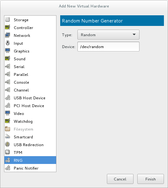
Figure 16.20. Random Number Generator window
Enter the intended parameters and click when done. The parameters are explained in virtio-rng elements.
Procedure 16.12. Implementing virtio-rng using command-line tools
- Shut down the guest virtual machine.
- Using the
virsh edit domain-namecommand, open the XML file for the intended guest virtual machine. - Edit the
<devices>element to include the following:... <devices> <rng model='virtio'> <rate period='2000' bytes='1234'/> <backend model='random'>/dev/random</backend> <!-- OR --> <backend model='egd' type='udp'> <source mode='bind' service='1234'/> <source mode='connect' host='1.2.3.4' service='1234'/> </backend> </rng> </devices> ...Figure 16.21. Random number generator device
The random number generator device allows the following XML attributes and elements:virtio-rng elements
<model>- The requiredmodelattribute specifies what type of RNG device is provided.<backend model>- The<backend>element specifies the source of entropy to be used for the guest. The source model is configured using themodelattribute. Supported source models include'random'and'egd'.<backend model='random'>- This<backend>type expects a non-blocking character device as input. Examples of such devices are/dev/randomand/dev/urandom. The file name is specified as contents of the<backend>element. When no file name is specified the hypervisor default is used.<backend model='egd'>- This back end connects to a source using the EGD protocol. The source is specified as a character device. See character device host physical machine interface for more information.
16.7. Assigning GPU Devices
- GPU PCI Device Assignment - Using this method, it is possible to remove a GPU device from the host and assign it to a single guest.
- NVIDIA vGPU Assignment - This method makes it possible to create multiple mediated devices from a physical GPU, and assign these devices as virtual GPUs to multiple guests. This is only supported on selected NVIDIA GPUs, and only one mediated device can be assigned to a single guest.
16.7.1. GPU PCI Device Assignment
- NVIDIA Quadro K-Series, M-Series, P-Series, and later architectures (models 2000 series or later)
- NVIDIA Tesla K-Series, M-Series, and later architectures
Note
lspci command, detach the device from host, attach it to the guest, and configure Xorg on the guest - as described in the following procedures:
Procedure 16.13. Enable IOMMU support in the host machine kernel
Edit the kernel command line
For an Intel VT-d system, IOMMU is activated by adding theintel_iommu=onandiommu=ptparameters to the kernel command line. For an AMD-Vi system, the option needed is onlyiommu=pt. To enable this option, edit or add theGRUB_CMDLINX_LINUXline to the/etc/sysconfig/grubconfiguration file as follows:GRUB_CMDLINE_LINUX="rd.lvm.lv=vg_VolGroup00/LogVol01 vconsole.font=latarcyrheb-sun16 rd.lvm.lv=vg_VolGroup_1/root vconsole.keymap=us $([ -x /usr/sbin/rhcrashkernel-param ] && /usr/sbin/rhcrashkernel-param || :) rhgb quiet intel_iommu=on iommu=pt"
Note
For further information on IOMMU, see Appendix E, Working with IOMMU Groups.Regenerate the boot loader configuration
For the changes to the kernel command line to apply, regenerate the boot loader configuration using thegrub2-mkconfigcommand:#
grub2-mkconfig -o /etc/grub2.cfgNote that if you are using a UEFI-based host, the target file should be/etc/grub2-efi.cfg.Reboot the host
For the changes to take effect, reboot the host machine:#
reboot
Procedure 16.14. Excluding the GPU device from binding to the host physical machine driver
Identify the PCI bus address
To identify the PCI bus address and IDs of the device, run the followinglspcicommand. In this example, a VGA controller such as an NVIDIA Quadro or GRID card is used:#
lspci -Dnn | grep VGA0000:02:00.0 VGA compatible controller [0300]: NVIDIA Corporation GK106GL [Quadro K4000] [10de:11fa] (rev a1)The resulting search reveals that the PCI bus address of this device is 0000:02:00.0 and the PCI IDs for the device are 10de:11fa.Prevent the native host machine driver from using the GPU device
To prevent the native host machine driver from using the GPU device, you can use a PCI ID with the pci-stub driver. To do this, append thepci-stub.idsoption, with the PCI IDs as its value, to theGRUB_CMDLINX_LINUXline located in the/etc/sysconfig/grubconfiguration file, for example as follows:GRUB_CMDLINE_LINUX="rd.lvm.lv=vg_VolGroup00/LogVol01 vconsole.font=latarcyrheb-sun16 rd.lvm.lv=vg_VolGroup_1/root vconsole.keymap=us $([ -x /usr/sbin/rhcrashkernel-param ] && /usr/sbin/rhcrashkernel-param || :) rhgb quiet intel_iommu=on iommu=pt pci-stub.ids=10de:11fa"
To add additional PCI IDs for pci-stub, separate them with a comma.Regenerate the boot loader configuration
Regenerate the boot loader configuration using thegrub2-mkconfigto include this option:#
grub2-mkconfig -o /etc/grub2.cfgNote that if you are using a UEFI-based host, the target file should be/etc/grub2-efi.cfg.Reboot the host machine
In order for the changes to take effect, reboot the host machine:#
reboot
Procedure 16.15. Optional: Editing the GPU IOMMU configuration
Display the XML information of the GPU
To display the settings of the GPU in XML form, you first need to convert its PCI bus address to libvirt-compatible format by appendingpci_and converting delimiters to underscores. In this example, the GPU PCI device identified with the 0000:02:00.0 bus address (as obtained in the previous procedure) becomespci_0000_02_00_0. Use the libvirt address of the device with thevirsh nodedev-dumpxmlto display its XML configuration:#
virsh nodedev-dumpxml pci_0000_02_00_0<device> <name>pci_0000_02_00_0</name> <path>/sys/devices/pci0000:00/0000:00:03.0/0000:02:00.0</path> <parent>pci_0000_00_03_0</parent> <driver> <name>pci-stub</name> </driver> <capability type='pci'> <domain>0</domain> <bus>2</bus> <slot>0</slot> <function>0</function> <product id='0x11fa'>GK106GL [Quadro K4000]</product> <vendor id='0x10de'>NVIDIA Corporation</vendor> <!-- pay attention to the following lines --> <iommuGroup number='13'> <address domain='0x0000' bus='0x02' slot='0x00' function='0x0'/> <address domain='0x0000' bus='0x02' slot='0x00' function='0x1'/> </iommuGroup> <pci-express> <link validity='cap' port='0' speed='8' width='16'/> <link validity='sta' speed='2.5' width='16'/> </pci-express> </capability> </device>Note the<iommuGroup>element of the XML. The iommuGroup indicates a set of devices that are considered isolated from other devices due to IOMMU capabilities and PCI bus topologies. All of the endpoint devices within the iommuGroup (meaning devices that are not PCIe root ports, bridges, or switch ports) need to be unbound from the native host drivers in order to be assigned to a guest. In the example above, the group is composed of the GPU device (0000:02:00.0) as well as the companion audio device (0000:02:00.1). For more information, see Appendix E, Working with IOMMU Groups.Adjust IOMMU settings
In this example, assignment of NVIDIA audio functions is not supported due to hardware issues with legacy interrupt support. In addition, the GPU audio function is generally not useful without the GPU itself. Therefore, in order to assign the GPU to a guest, the audio function must first be detached from native host drivers. This can be done using one of the following:- Detect the PCI ID for the device and append it to the
pci-stub.idsoption in the/etc/sysconfig/grubfile, as detailed in Procedure 16.14, “Excluding the GPU device from binding to the host physical machine driver” - Use the
virsh nodedev-detachcommand, for example as follows:#
virsh nodedev-detach pci_0000_02_00_1Device pci_0000_02_00_1 detached
Procedure 16.16. Attaching the GPU
- Using the Virtual Machine Manager interface. For details, see Section 16.1.2, “Assigning a PCI Device with virt-manager”.
- Creating an XML configuration fragment for the GPU and attaching it with the
virsh attach-device:- Create an XML for the device, similar to the following:
<hostdev mode='subsystem' type='pci' managed='yes'> <driver name='vfio'/> <source> <address domain='0x0000' bus='0x02' slot='0x00' function='0x0'/> </source> </hostdev>
- Save this to a file and run
virsh attach-device [domain] [file] --persistentto include the XML in the guest configuration. Note that the assigned GPU is added in addition to the existing emulated graphics device in the guest machine. The assigned GPU is handled as a secondary graphics device in the virtual machine. Assignment as a primary graphics device is not supported and emulated graphics devices in the guest's XML should not be removed.
- Editing the guest XML configuration using the
virsh editcommand and adding the appropriate XML segment manually.
Procedure 16.17. Ḿodifying the Xorg configuration on the guest
- In the guest, use the
lspcicommand to determine the PCI bus adress of the GPU:#
lspci | grep VGA00:02.0 VGA compatible controller: Device 1234:111 00:09.0 VGA compatible controller: NVIDIA Corporation GK106GL [Quadro K4000] (rev a1)In this example, the bus address is 00:09.0. - In the
/etc/X11/xorg.conffile on the guest, add aBusIDoption with the detected address adjusted as follows:Section "Device" Identifier "Device0" Driver "nvidia" VendorName "NVIDIA Corporation" BusID "PCI:0:9:0" EndSection
Important
If the bus address detected in Step 1 is hexadecimal, you need to convert the values between delimiters to the decimal system. For example, 00:0a.0 should be converted into PCI:0:10:0.
Note
modprobe.blacklist=nouveau on the kernel command line during install. For information on other guest virtual machines, see the operating system's specific documentation.
16.7.2. NVIDIA vGPU Assignment
Important
16.7.2.1. NVIDIA vGPU Setup
- Obtain the NVIDIA vGPU drivers and install them on your system. For instructions, see the NVIDIA documentation.
- If the NVIDIA software installer did not create the
/etc/modprobe.d/nvidia-installer-disable-nouveau.conffile, create a.conffile (of any name) in the/etc/modprobe.d/directory. Add the following lines in the file:blacklist nouveau options nouveau modeset=0
- Regenerate the initial ramdisk for the current kernel, then reboot:
#
dracut --force#rebootIf you need to use a prior supported kernel version with mediated devices, regenerate the initial ramdisk for all installed kernel versions:#
dracut --regenerate-all --force#reboot - Check that the
nvidia_vgpu_vfiomodule has been loaded by the kernel and that thenvidia-vgpu-mgr.serviceservice is running.#
lsmod | grep nvidia_vgpu_vfionvidia_vgpu_vfio 45011 0 nvidia 14333621 10 nvidia_vgpu_vfio mdev 20414 2 vfio_mdev,nvidia_vgpu_vfio vfio 32695 3 vfio_mdev,nvidia_vgpu_vfio,vfio_iommu_type1 #systemctl status nvidia-vgpu-mgr.servicenvidia-vgpu-mgr.service - NVIDIA vGPU Manager Daemon Loaded: loaded (/usr/lib/systemd/system/nvidia-vgpu-mgr.service; enabled; vendor preset: disabled) Active: active (running) since Fri 2018-03-16 10:17:36 CET; 5h 8min ago Main PID: 1553 (nvidia-vgpu-mgr) [...] - Write a device UUID to
/sys/class/mdev_bus/pci_dev/mdev_supported_types/type-id/create, where pci_dev is the PCI address of the host GPU, and type-id is an ID of the host GPU type.The following example shows how to create a mediated device ofnvidia-63vGPU type on an NVIDIA Tesla P4 card:#
uuidgen30820a6f-b1a5-4503-91ca-0c10ba58692a #echo "30820a6f-b1a5-4503-91ca-0c10ba58692a" > /sys/class/mdev_bus/0000:01:00.0/mdev_supported_types/nvidia-63/createFor type-id values for specific devices, see section 1.3.1. Virtual GPU Types in Virtual GPU software documentation. Note that only Q-series NVIDIA vGPUs, such asGRID P4-2Q, are supported as mediated device GPU types on Linux guests. - Add the following lines to the <devices/> sections in XML configurations of guests that you want to share the vGPU resources. Use the UUID value generated by the
uuidgencommand in the previous step. Each UUID can only be assigned to one guest at a time.<hostdev mode='subsystem' type='mdev' managed='no' model='vfio-pci'> <source> <address uuid='30820a6f-b1a5-4503-91ca-0c10ba58692a'/> </source> </hostdev>Important
For the vGPU mediated devices to work properly on the assigned guests, NVIDIA vGPU guest software licensing needs to be set up for the guests. For further information and instructions, see the NVIDIA virtual GPU software documentation.
16.7.2.2. Setting up and using the VNC console for video streaming with NVIDIA vGPU
Warning
- Install NVIDIA vGPU drivers and configure NVIDIA vGPU on your system as described in Section 16.7.2.1, “NVIDIA vGPU Setup”. Ensure the mediated device's XML configuration includes the display='on' parameter. For example:
<hostdev mode='subsystem' type='mdev' managed='no' model='vfio-pci' display='on'> <source> <address uuid='ba26a3e2-8e1e-4f39-9de7-b26bd210268a'/> </source> </hostdev> - Optionally, set the VM's video model type as none. For example:
<video> <model type='none'/> </video>
If this is not specified, you receive two different display outputs - one from an emulated Cirrus or QXL card and one from NVIDIA vGPU. Also note that using model type='none' currently makes it impossible to see the boot graphical output until the drivers are initialized. As a result, the first graphical output displayed is the login screen. - Ensure the XML configuration of the VM's graphics type is vnc.For example:
<graphics type='vnc' port='-1' autoport='yes'> <listen type='address'/> </graphics>
- Start the virtual machine.
- Connect to the virtual machine using the VNC viewer remote desktop client.
Note
If the VM is set up with an emulated VGA as the primary video device and vGPU as the secondary device, use the ctrl+alt+2 keyboard shortcut to switch to the vGPU display.
16.7.2.3. Removing NVIDIA vGPU Devices
30820a6f-b1a5-4503-91ca-0c10ba58692a.
# echo 1 > /sys/bus/mdev/devices/uuid/removeecho: write error: Device or resource busy
16.7.2.4. Querying NVIDIA vGPU Capabilities
virsh nodedev-list --cap mdev_types and virsh nodedev-dumpxml commands. For example, the following displays available vGPU types on a Tesla P4 card:
$ virsh nodedev-list --cap mdev_types
pci_0000_01_00_0
$ virsh nodedev-dumpxml pci_0000_01_00_0
<...>
<capability type='mdev_types'>
<type id='nvidia-70'>
<name>GRID P4-8A</name>
<deviceAPI>vfio-pci</deviceAPI>
<availableInstances>1</availableInstances>
</type>
<type id='nvidia-69'>
<name>GRID P4-4A</name>
<deviceAPI>vfio-pci</deviceAPI>
<availableInstances>2</availableInstances>
</type>
<type id='nvidia-67'>
<name>GRID P4-1A</name>
<deviceAPI>vfio-pci</deviceAPI>
<availableInstances>8</availableInstances>
</type>
<type id='nvidia-65'>
<name>GRID P4-4Q</name>
<deviceAPI>vfio-pci</deviceAPI>
<availableInstances>2</availableInstances>
</type>
<type id='nvidia-63'>
<name>GRID P4-1Q</name>
<deviceAPI>vfio-pci</deviceAPI>
<availableInstances>8</availableInstances>
</type>
<type id='nvidia-71'>
<name>GRID P4-1B</name>
<deviceAPI>vfio-pci</deviceAPI>
<availableInstances>8</availableInstances>
</type>
<type id='nvidia-68'>
<name>GRID P4-2A</name>
<deviceAPI>vfio-pci</deviceAPI>
<availableInstances>4</availableInstances>
</type>
<type id='nvidia-66'>
<name>GRID P4-8Q</name>
<deviceAPI>vfio-pci</deviceAPI>
<availableInstances>1</availableInstances>
</type>
<type id='nvidia-64'>
<name>GRID P4-2Q</name>
<deviceAPI>vfio-pci</deviceAPI>
<availableInstances>4</availableInstances>
</type>
</capability>
</...>
16.7.2.5. Remote Desktop Streaming Services for NVIDIA vGPU
- HP-RGS
- Mechdyne TGX - It is currently not possible to use Mechdyne TGX with Windows Server 2016 guests.
- NICE DCV - When using this streaming service, Red Hat recommends using fixed resolution settings, as using dynamic resolution in some cases results in a black screen.
16.7.2.6. Setting up the VNC console for video streaming with NVIDIA vGPU
Introduction
Important
Configuration
- Install NVIDIA vGPU drivers and configure NVIDIA vGPU on your host as described in Section 16.7.2, “NVIDIA vGPU Assignment”. Ensure the mediated device's XML configuration includes the display='on' parameter. For example:
<hostdev mode='subsystem' type='mdev' managed='no' model='vfio-pci' display='on'> <source> <address uuid='ba26a3e2-8e1e-4f39-9de7-b26bd210268a'/> </source> </hostdev> - Optionally, set the VM's video model type as none. For example:
<video> <model type='none'/> </video>
- Ensure the XML configuration of the VM's graphics type is spice or vnc.An example for spice:
<graphics type='spice' autoport='yes'> <listen type='address'/> <image compression='off'/> </graphics>
An example for vnc:<graphics type='vnc' port='-1' autoport='yes'> <listen type='address'/> </graphics>
- Start the virtual machine.
- Connect to the virtual machine using a client appropriate to the graphics protocol you configured in the previous steps.
- For VNC, use the VNC viewer remote desktop client. If the VM is set up with an emulated VGA as the primary video device and vGPU as the secondary, use the ctrl+alt+2 keyboard shortcut to switch to the vGPU display.
- For SPICE, use the virt-viewer application.
Chapter 17. Virtual Networking
17.1. Virtual Network Switches

Figure 17.1. Virtual network switch with two guests
libvirtd) is first installed and started, the default network interface representing the virtual network switch is virbr0.
virbr0 interface can be viewed with the ip command like any other interface:
$ ip addr show virbr0
3: virbr0: <BROADCAST,MULTICAST,UP,LOWER_UP> mtu 1500 qdisc noqueue state UNKNOWN
link/ether 1b:c4:94:cf:fd:17 brd ff:ff:ff:ff:ff:ff
inet 192.168.122.1/24 brd 192.168.122.255 scope global virbr0
17.2. Bridged Mode
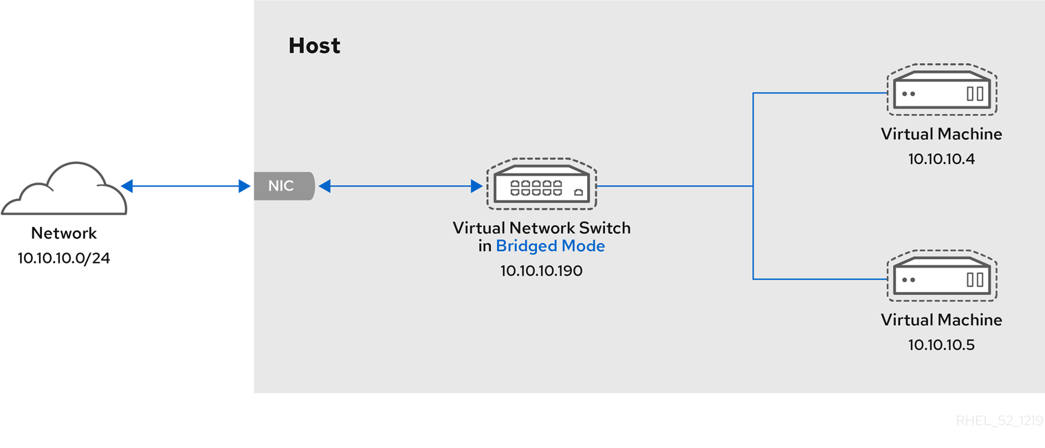
Figure 17.2. Virtual network switch in bridged mode
Warning
17.3. Network Address Translation
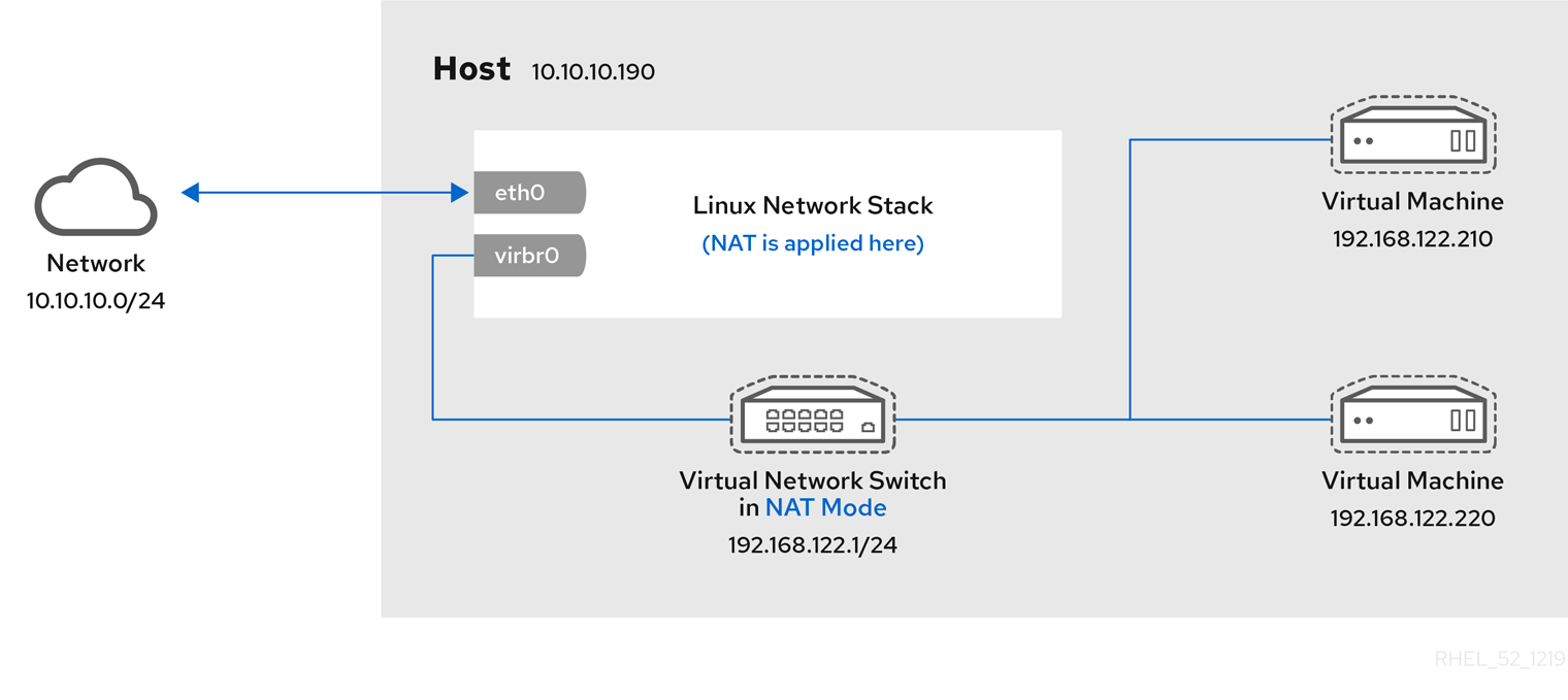
Figure 17.3. Virtual network switch using NAT with two guests
Warning
# iptables -j SNAT --to-source [start]-[end]17.4. DNS and DHCP
dnsmasq program for this. An instance of dnsmasq is automatically configured and started by libvirt for each virtual network switch that needs it.
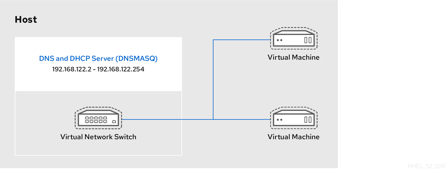
Figure 17.4. Virtual network switch running dnsmasq
17.5. Routed Mode
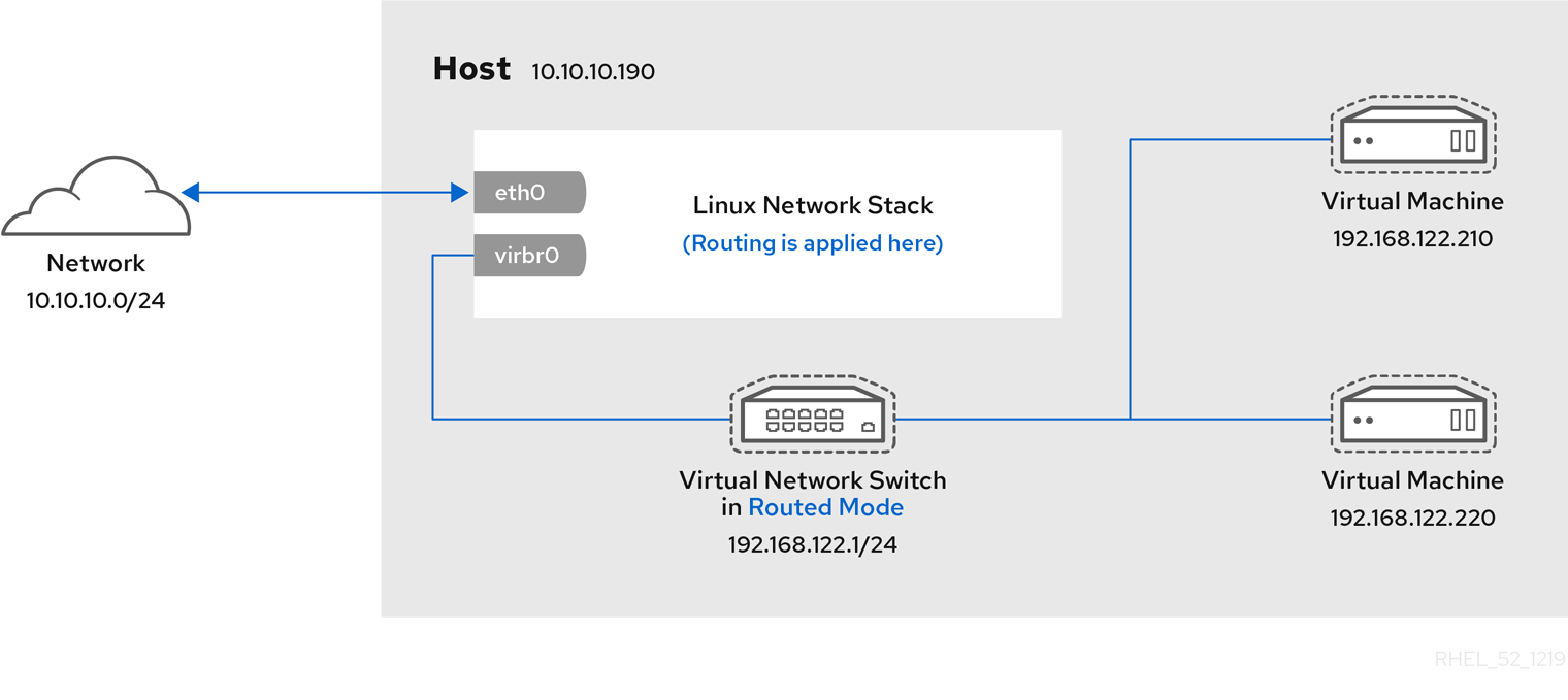
Figure 17.5. Virtual network switch in routed mode
17.6. Isolated Mode
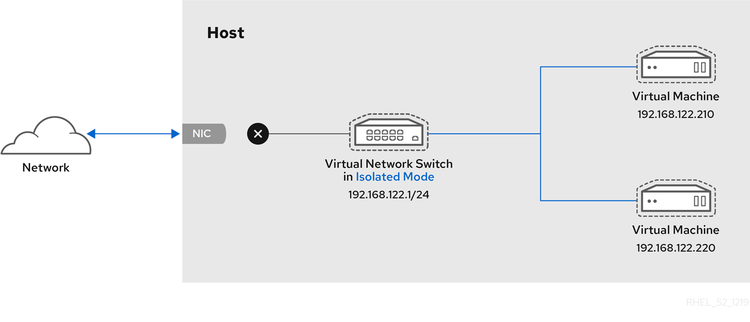
Figure 17.6. Virtual network switch in isolated mode
17.7. The Default Configuration
libvirtd) is first installed, it contains an initial virtual network switch configuration in NAT mode. This configuration is used so that installed guests can communicate to the external network, through the host physical machine. The following image demonstrates this default configuration for libvirtd:
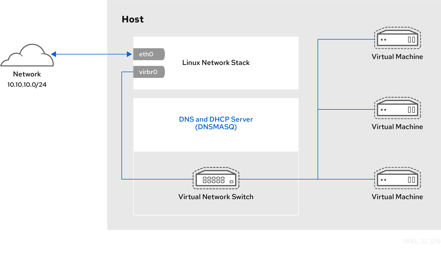
Figure 17.7. Default libvirt network configuration
Note
eth0, eth1 and eth2). This is only useful in routed and NAT modes, and can be defined in the dev=<interface> option, or in virt-manager when creating a new virtual network.
17.8. Examples of Common Scenarios
17.8.1. Bridged Mode
- Deploying guest virtual machines in an existing network alongside host physical machines making the difference between virtual and physical machines transparent to the end user.
- Deploying guest virtual machines without making any changes to existing physical network configuration settings.
- Deploying guest virtual machines which must be easily accessible to an existing physical network. Placing guest virtual machines on a physical network where they must access services within an existing broadcast domain, such as DHCP.
- Connecting guest virtual machines to an exsting network where VLANs are used.
17.8.2. Routed Mode
Consider a network where one or more nodes are placed in a controlled sub-network for security reasons. The deployment of a special sub-network such as this is a common practice, and the sub-network is known as a DMZ. See the following diagram for more details on this layout:
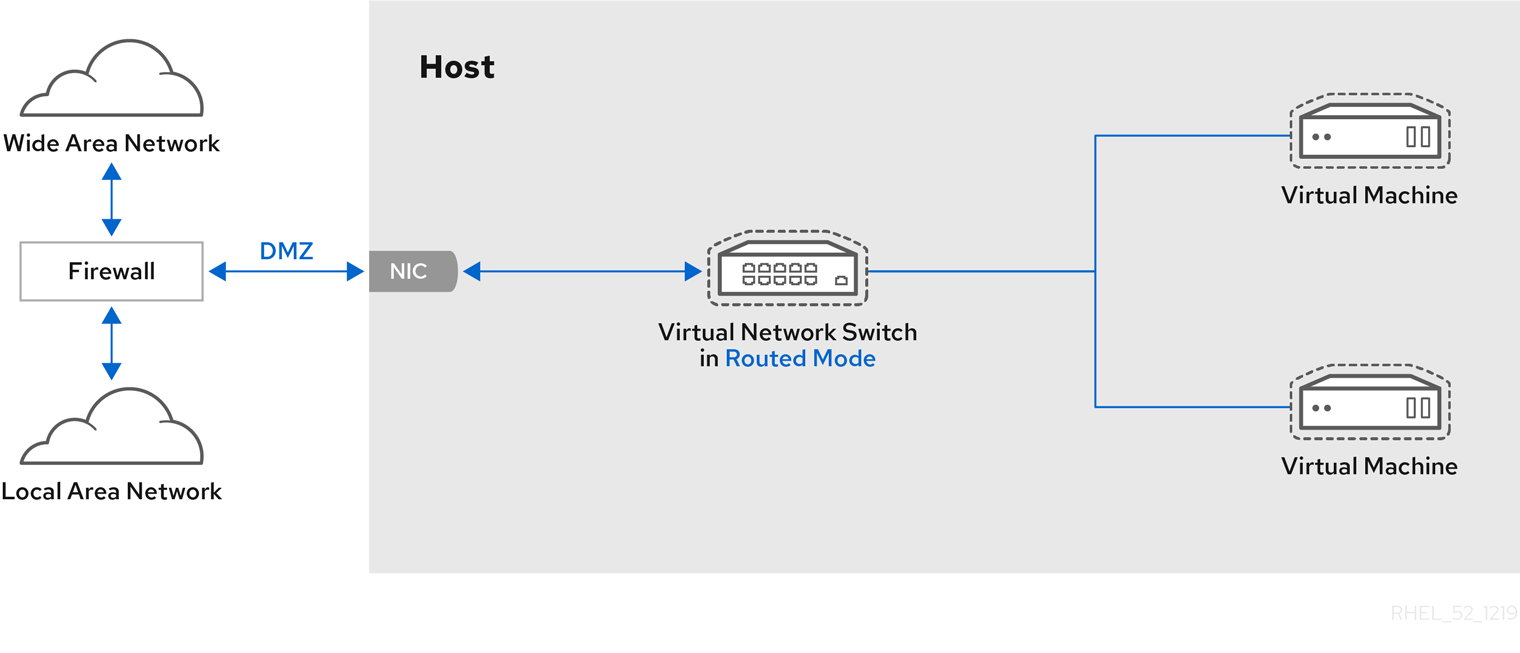
Figure 17.8. Sample DMZ configuration
Consider a virtual server hosting company that has several host physical machines, each with two physical network connections. One interface is used for management and accounting, the other is for the virtual machines to connect through. Each guest has its own public IP address, but the host physical machines use private IP address as management of the guests can only be performed by internal administrators. See the following diagram to understand this scenario:
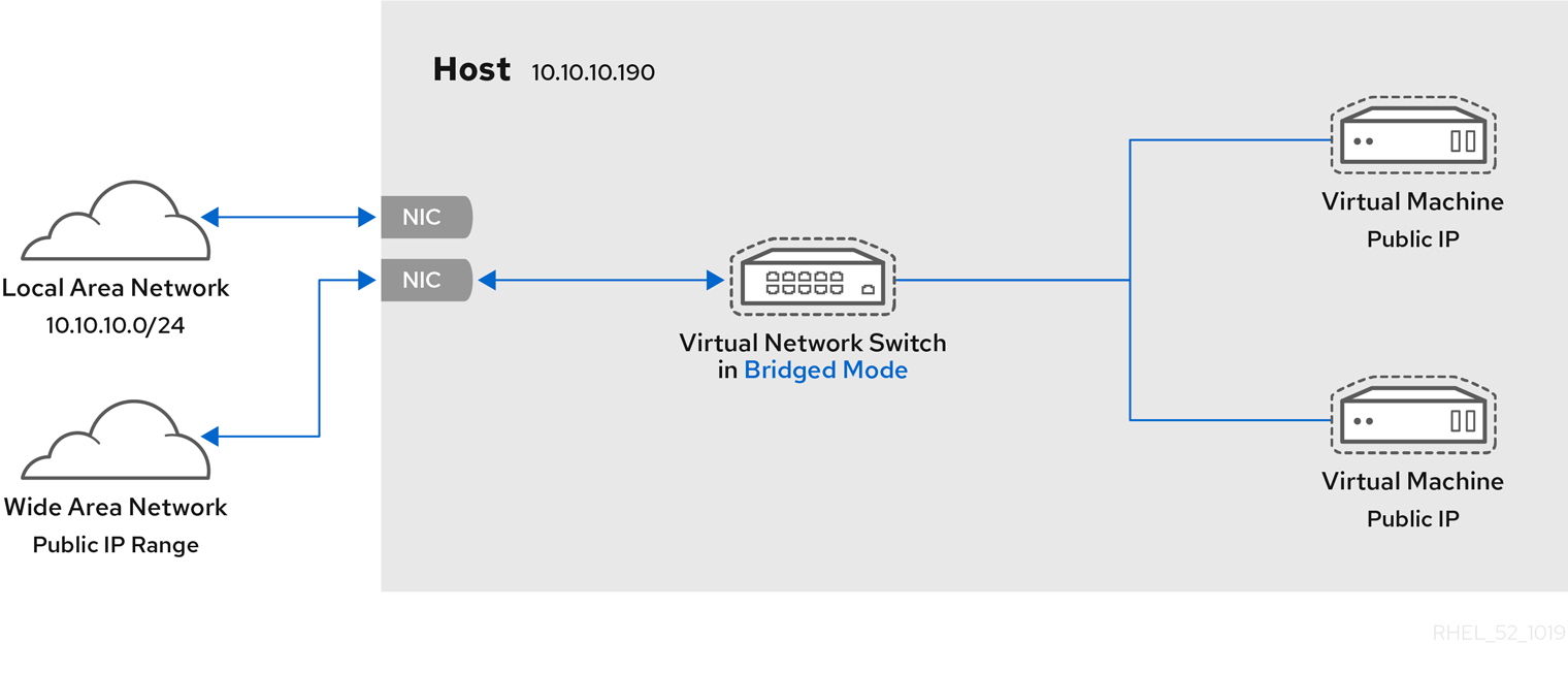
Figure 17.9. Virtual server hosting sample configuration
17.8.3. NAT Mode
17.8.4. Isolated Mode
17.9. Managing a Virtual Network
- From the Edit menu, select Connection Details.
- This will open the menu. Click the Virtual Networks tab.
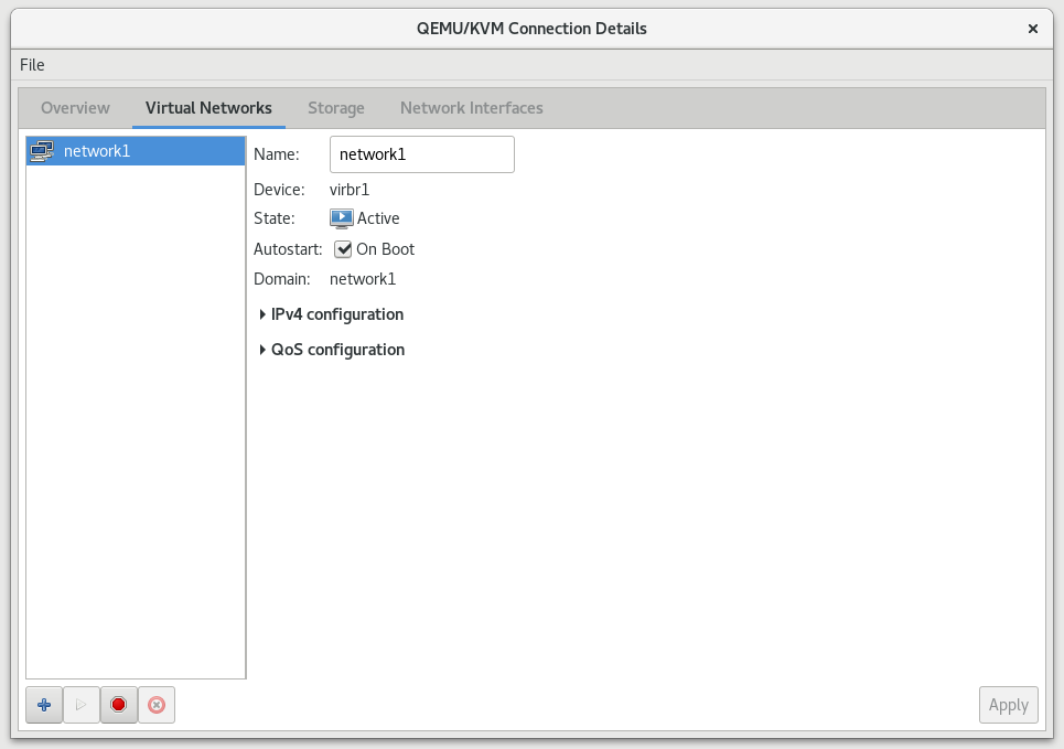
Figure 17.10. Virtual network configuration
- All available virtual networks are listed on the left of the menu. You can edit the configuration of a virtual network by selecting it from this box and editing as you see fit.
17.10. Creating a Virtual Network
- Open the Virtual Networks tab from within the Connection Details menu. Click the button, identified by a plus sign (+) icon. For more information, see Section 17.9, “Managing a Virtual Network”.
Figure 17.11. Virtual network configuration
This will open the window. Click to continue.
Figure 17.12. Naming your new virtual network
- Enter an appropriate name for your virtual network and click .
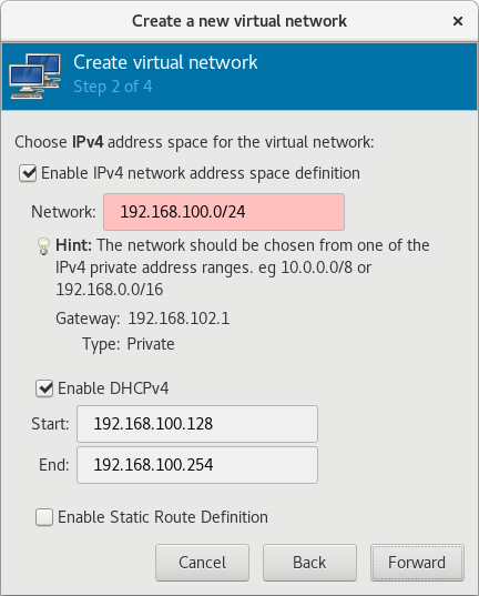
Figure 17.13. Choosing an IPv4 address space
- Check the Enable IPv4 network address space definition check box.Enter an IPv4 address space for your virtual network in the Network field.Check the Enable DHCPv4 check box.Define the DHCP range for your virtual network by specifying a Start and End range of IP addresses.

Figure 17.14. Choosing an IPv4 address space
Click to continue. - If you want to enable IPv6, check the Enable IPv6 network address space definition.

Figure 17.15. Enabling IPv6
Additional fields appear in the Create a new virtual network window.
Figure 17.16. Configuring IPv6
Enter an IPv6 address in the Network field. - If you want to enable DHCPv6, check the Enable DHCPv6 check box.Additional fields appear in the Create a new virtual network window.

Figure 17.17. Configuring DHCPv6
(Optional) Edit the start and end of the DHCPv6 range. - If you want to enable static route definitions, check the Enable Static Route Definition check box.Additional fields appear in the Create a new virtual network window.
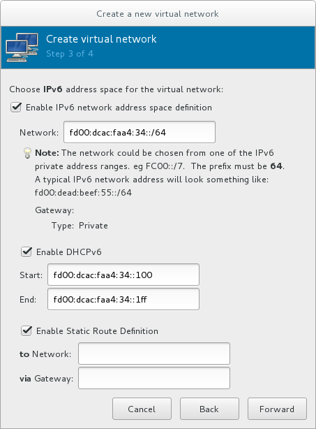
Figure 17.18. Defining static routes
Enter a network address and the gateway that will be used for the route to the network in the appropriate fields.Click . - Select how the virtual network should connect to the physical network.
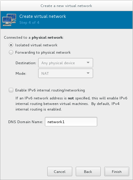
Figure 17.19. Connecting to the physical network
If you want the virtual network to be isolated, ensure that the Isolated virtual network radio button is selected.If you want the virtual network to connect to a physical network, select Forwarding to physical network, and choose whether the Destination should be Any physical device or a specific physical device. Also select whether the Mode should be NAT or Routed.If you want to enable IPv6 routing within the virtual network, check the Enable IPv6 internal routing/networking check box.Enter a DNS domain name for the virtual network.Click to create the virtual network. - The new virtual network is now available in the Virtual Networks tab of the Connection Details window.
17.11. Attaching a Virtual Network to a Guest
- In the Virtual Machine Manager window, highlight the guest that will have the network assigned.
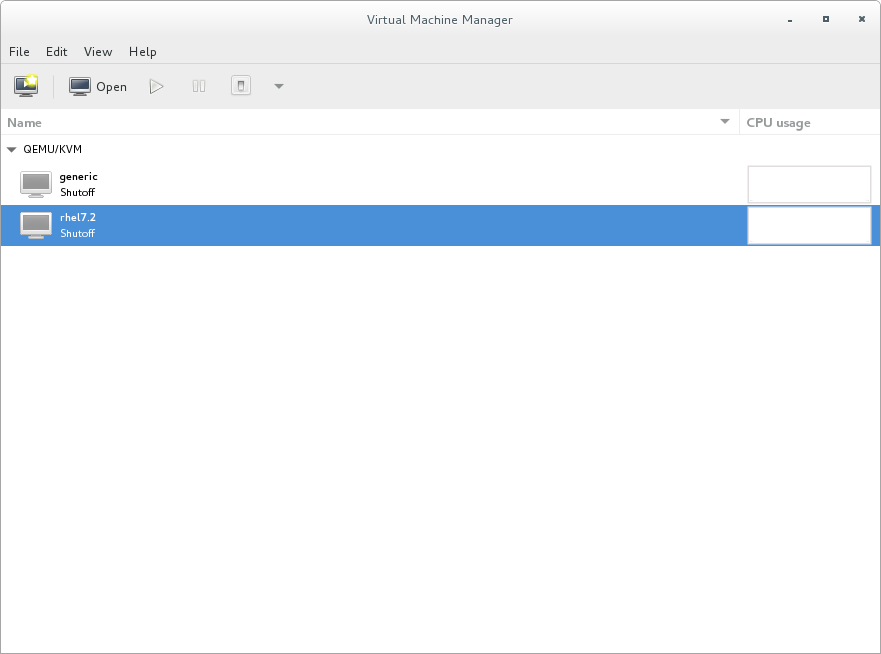
Figure 17.20. Selecting a virtual machine to display
- From the Virtual Machine Manager Edit menu, select Virtual Machine Details.
- Click the Add Hardware button on the Virtual Machine Details window.
- In the Add new virtual hardware window, select Network from the left pane, and select your network name (network1 in this example) from the Network source menu. Modify the MAC address, if necessary, and select a Device model. Click .
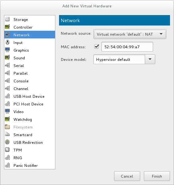
Figure 17.21. Select your network from the Add new virtual hardware window
- The new network is now displayed as a virtual network interface that will be presented to the guest upon launch.
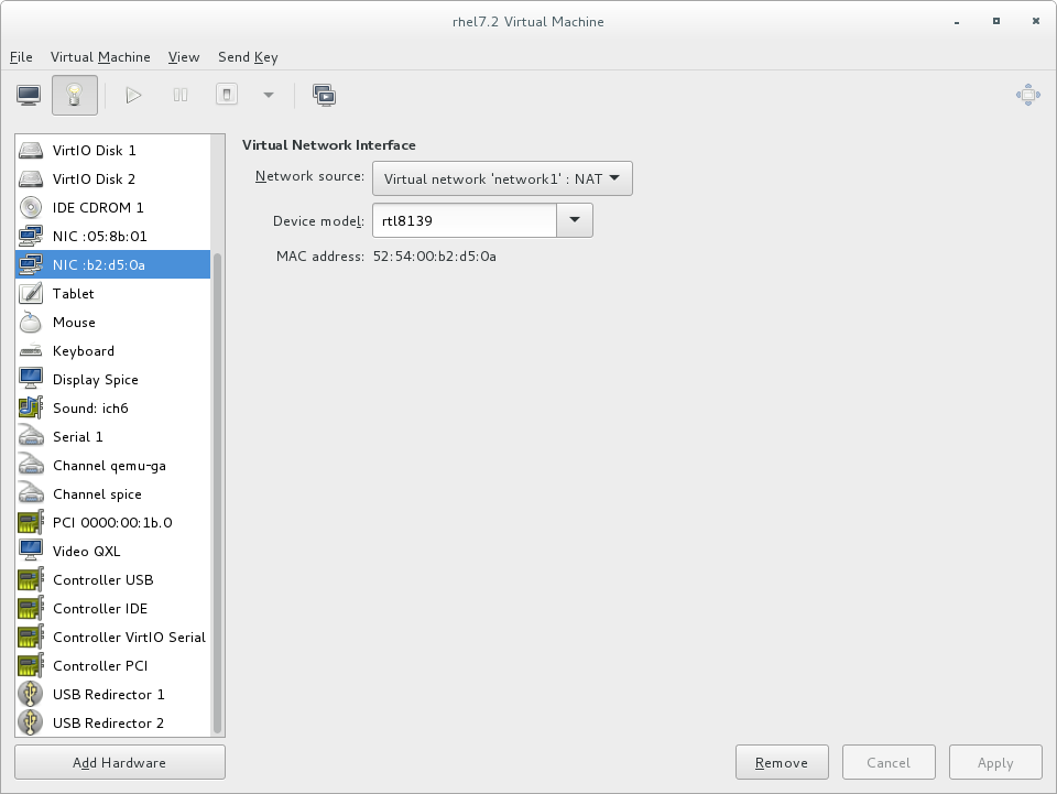
Figure 17.22. New network shown in guest hardware list
17.12. Attaching a Virtual NIC Directly to a Physical Interface
Physical interface delivery modes
- VEPA
- In virtual ethernet port aggregator (VEPA) mode, all packets from the guests are sent to the external switch. This enables the user to force guest traffic through the switch. For VEPA mode to work correctly, the external switch must also support hairpin mode, which ensures that packets whose destination is a guest on the same host machine as their source guest are sent back to the host by the external switch.

Figure 17.23. VEPA mode
- bridge
- Packets whose destination is on the same host machine as their source guest are directly delivered to the target macvtap device. Both the source device and the destination device need to be in bridge mode for direct delivery to succeed. If either one of the devices is in VEPA mode, a hairpin-capable external switch is required.

Figure 17.24. Bridge mode
- private
- All packets are sent to the external switch and will only be delivered to a target guest on the same host machine if they are sent through an external router or gateway and these send them back to the host. Private mode can be used to prevent the individual guests on the single host from communicating with each other. This procedure is followed if either the source or destination device is in private mode.
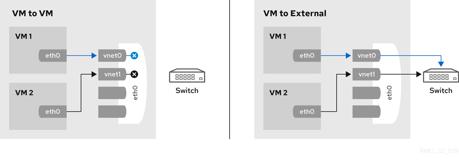
Figure 17.25. Private mode
- passthrough
- This feature attaches a physical interface device or a SR-IOV Virtual Function (VF) directly to a guest without losing the migration capability. All packets are sent directly to the designated network device. Note that a single network device can only be passed through to a single guest, as a network device cannot be shared between guests in passthrough mode.
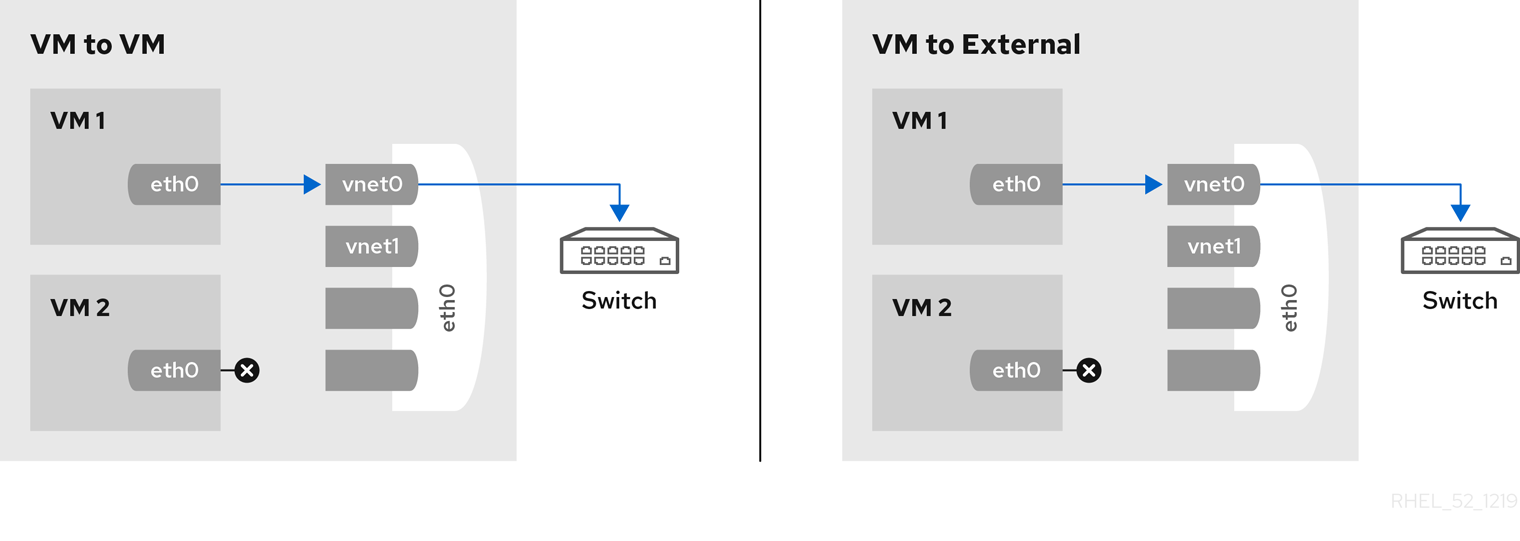
Figure 17.26. Passthrough mode
17.12.1. Configuring macvtap using domain XML
<devices> element as follows:
<devices> ... <interface type='direct'> <source dev='eth0' mode='vepa'/> </interface> </devices>
Virtual Station Interface types
- managerid
- The VSI Manager ID identifies the database containing the VSI type and instance definitions. This is an integer value and the value 0 is reserved.
- typeid
- The VSI Type ID identifies a VSI type characterizing the network access. VSI types are typically managed by network administrator. This is an integer value.
- typeidversion
- The VSI Type Version allows multiple versions of a VSI Type. This is an integer value.
- instanceid
- The VSI Instance ID is generated when a VSI instance (a virtual interface of a virtual machine) is created. This is a globally unique identifier.
- profileid
- The profile ID contains the name of the port profile that is to be applied onto this interface. This name is resolved by the port profile database into the network parameters from the port profile, and those network parameters will be applied to this interface.
<devices>
...
<interface type='direct'>
<source dev='eth0.2' mode='vepa'/>
<virtualport type="802.1Qbg">
<parameters managerid="11" typeid="1193047" typeidversion="2" instanceid="09b11c53-8b5c-4eeb-8f00-d84eaa0aaa4f"/>
</virtualport>
</interface>
</devices>
<devices>
...
<interface type='direct'>
<source dev='eth0' mode='private'/>
<virtualport type='802.1Qbh'>
<parameters profileid='finance'/>
</virtualport>
</interface>
</devices>
...
17.12.2. Configuring macvtap using virt-manager
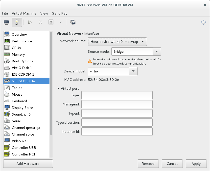
Figure 17.27. Configuring macvtap in virt-manager
17.13. Dynamically Changing a Host Physical Machine or a Network Bridge that is Attached to a Virtual NIC
- Prepare guest virtual machine with a configuration similar to the following:
<interface type='bridge'> <mac address='52:54:00:4a:c9:5e'/> <source bridge='virbr0'/> <model type='virtio'/> </interface> - Prepare an XML file for interface update:
#
cat br1.xml<interface type='bridge'> <mac address='52:54:00:4a:c9:5e'/> <source bridge='virbr1'/> <model type='virtio'/> </interface> - Start the guest virtual machine, confirm the guest virtual machine's network functionality, and check that the guest virtual machine's vnetX is connected to the bridge you indicated.
# brctl showbridge name bridge id STP enabled interfaces virbr0 8000.5254007da9f2 yes virbr0-nic vnet0 virbr1 8000.525400682996 yes virbr1-nic - Update the guest virtual machine's network with the new interface parameters with the following command:
# virsh update-device test1 br1.xmlDevice updated successfully - On the guest virtual machine, run
service network restart. The guest virtual machine gets a new IP address for virbr1. Check the guest virtual machine's vnet0 is connected to the new bridge(virbr1)#
brctl showbridge name bridge id STP enabled interfaces virbr0 8000.5254007da9f2 yes virbr0-nic virbr1 8000.525400682996 yes virbr1-nic vnet0
17.14. Applying Network Filtering
17.14.1. Introduction
- network
- ethernet -- must be used in bridging mode
- bridge
Example 17.1. An example of network filtering
<devices>
<interface type='bridge'>
<mac address='00:16:3e:5d:c7:9e'/>
<filterref filter='clean-traffic'/>
</interface>
</devices>
# virsh nwfilter-dumpxml clean-traffic.
Example 17.2. Description extended
<devices>
<interface type='bridge'>
<mac address='00:16:3e:5d:c7:9e'/>
<filterref filter='clean-traffic'>
<parameter name='IP' value='10.0.0.1'/>
</filterref>
</interface>
</devices>
17.14.2. Filtering Chains
- root
- mac
- stp (spanning tree protocol)
- vlan
- arp and rarp
- ipv4
- ipv6
Example 17.3. ARP traffic filtering
<filter name='no-arp-spoofing' chain='arp' priority='-500'>
<uuid>f88f1932-debf-4aa1-9fbe-f10d3aa4bc95</uuid>
<rule action='drop' direction='out' priority='300'>
<mac match='no' srcmacaddr='$MAC'/>
</rule>
<rule action='drop' direction='out' priority='350'>
<arp match='no' arpsrcmacaddr='$MAC'/>
</rule>
<rule action='drop' direction='out' priority='400'>
<arp match='no' arpsrcipaddr='$IP'/>
</rule>
<rule action='drop' direction='in' priority='450'>
<arp opcode='Reply'/>
<arp match='no' arpdstmacaddr='$MAC'/>
</rule>
<rule action='drop' direction='in' priority='500'>
<arp match='no' arpdstipaddr='$IP'/>
</rule>
<rule action='accept' direction='inout' priority='600'>
<arp opcode='Request'/>
</rule>
<rule action='accept' direction='inout' priority='650'>
<arp opcode='Reply'/>
</rule>
<rule action='drop' direction='inout' priority='1000'/>
</filter>
17.14.3. Filtering Chain Priorities
Table 17.1. Filtering chain default priorities values
| Chain (prefix) | Default priority |
|---|---|
| stp | -810 |
| mac | -800 |
| vlan | -750 |
| ipv4 | -700 |
| ipv6 | -600 |
| arp | -500 |
| rarp | -400 |
Note
17.14.4. Usage of Variables in Filters
MAC is designated for the MAC address of the network interface. A filtering rule that references this variable will automatically be replaced with the MAC address of the interface. This works without the user having to explicitly provide the MAC parameter. Even though it is possible to specify the MAC parameter similar to the IP parameter above, it is discouraged since libvirt knows what MAC address an interface will be using.
IP represents the IP address that the operating system inside the virtual machine is expected to use on the given interface. The IP parameter is special in so far as the libvirt daemon will try to determine the IP address (and thus the IP parameter's value) that is being used on an interface if the parameter is not explicitly provided but referenced. For current limitations on IP address detection, consult the section on limitations Section 17.14.12, “Limitations” on how to use this feature and what to expect when using it. The XML file shown in Section 17.14.2, “Filtering Chains” contains the filter no-arp-spoofing, which is an example of using a network filter XML to reference the MAC and IP variables.
$. The format of the value of a variable must be of the type expected by the filter attribute identified in the XML. In the above example, the IP parameter must hold a legal IP address in standard format. Failure to provide the correct structure will result in the filter variable not being replaced with a value and will prevent a virtual machine from starting or will prevent an interface from attaching when hot plugging is being used. Some of the types that are expected for each XML attribute are shown in the example Example 17.4, “Sample variable types”.
Example 17.4. Sample variable types
<devices>
<interface type='bridge'>
<mac address='00:16:3e:5d:c7:9e'/>
<filterref filter='clean-traffic'>
<parameter name='IP' value='10.0.0.1'/>
<parameter name='IP' value='10.0.0.2'/>
<parameter name='IP' value='10.0.0.3'/>
</filterref>
</interface>
</devices>
<rule action='accept' direction='in' priority='500'>
<tcp srpipaddr='$IP'/>
</rule>
<rule action='accept' direction='in' priority='500'>
<udp dstportstart='$DSTPORTS[1]'/>
</rule>
Example 17.5. Using a variety of variables
$VARIABLE[@<iterator id="x">]. The following rule allows a virtual machine to receive traffic on a set of ports, which are specified in DSTPORTS, from the set of source IP address specified in SRCIPADDRESSES. The rule generates all combinations of elements of the variable DSTPORTS with those of SRCIPADDRESSES by using two independent iterators to access their elements.
<rule action='accept' direction='in' priority='500'>
<ip srcipaddr='$SRCIPADDRESSES[@1]' dstportstart='$DSTPORTS[@2]'/>
</rule>
SRCIPADDRESSES = [ 10.0.0.1, 11.1.2.3 ] DSTPORTS = [ 80, 8080 ]
$SRCIPADDRESSES[@1] and $DSTPORTS[@2] would then result in all variants of addresses and ports being created as shown:
- 10.0.0.1, 80
- 10.0.0.1, 8080
- 11.1.2.3, 80
- 11.1.2.3, 8080
$SRCIPADDRESSES[@1] and $DSTPORTS[@1], would result in parallel access to both lists and result in the following combination:
- 10.0.0.1, 80
- 11.1.2.3, 8080
Note
$VARIABLE is short-hand for $VARIABLE[@0]. The former notation always assumes the role of iterator with iterator id="0" added as shown in the opening paragraph at the top of this section.
17.14.5. Automatic IP Address Detection and DHCP Snooping
17.14.5.1. Introduction
CTRL_IP_LEARNING can be used to specify the IP address learning method to use. Valid values include: any, dhcp, or none.
CTRL_IP_LEARNING is not set. This method will only detect a single IP address per interface. Once a guest virtual machine's IP address has been detected, its IP network traffic will be locked to that address, if for example, IP address spoofing is prevented by one of its filters. In that case, the user of the VM will not be able to change the IP address on the interface inside the guest virtual machine, which would be considered IP address spoofing. When a guest virtual machine is migrated to another host physical machine or resumed after a suspend operation, the first packet sent by the guest virtual machine will again determine the IP address that the guest virtual machine can use on a particular interface.
17.14.5.2. DHCP Snooping
CTRL_IP_LEARNING=dhcp (DHCP snooping) provides additional anti-spoofing security, especially when combined with a filter allowing only trusted DHCP servers to assign IP addresses. To enable this, set the variable DHCPSERVER to the IP address of a valid DHCP server and provide filters that use this variable to filter incoming DHCP responses.
Note
Example 17.6. Activating IPs for DHCP snooping
<interface type='bridge'>
<source bridge='virbr0'/>
<filterref filter='clean-traffic'>
<parameter name='CTRL_IP_LEARNING' value='dhcp'/>
</filterref>
</interface>
17.14.6. Reserved Variables
Table 17.2. Reserved variables
| Variable Name | Definition |
|---|---|
| MAC | The MAC address of the interface |
| IP | The list of IP addresses in use by an interface |
| IPV6 | Not currently implemented: the list of IPV6 addresses in use by an interface |
| DHCPSERVER | The list of IP addresses of trusted DHCP servers |
| DHCPSERVERV6 | Not currently implemented: The list of IPv6 addresses of trusted DHCP servers |
| CTRL_IP_LEARNING | The choice of the IP address detection mode |
17.14.7. Element and Attribute Overview
<filter> with two possible attributes. The name attribute provides a unique name of the given filter. The chain attribute is optional but allows certain filters to be better organized for more efficient processing by the firewall subsystem of the underlying host physical machine. Currently, the system only supports the following chains: root, ipv4, ipv6, arp and rarp.
17.14.8. References to Other Filters
Example 17.7. An Example of a clean traffic filter
<filter name='clean-traffic'> <uuid>6ef53069-ba34-94a0-d33d-17751b9b8cb1</uuid> <filterref filter='no-mac-spoofing'/> <filterref filter='no-ip-spoofing'/> <filterref filter='allow-incoming-ipv4'/> <filterref filter='no-arp-spoofing'/> <filterref filter='no-other-l2-traffic'/> <filterref filter='qemu-announce-self'/> </filter>
<filterref> needs to be provided inside a filter node. This node must have the attribute filter whose value contains the name of the filter to be referenced.
17.14.9. Filter Rules
Example 17.8. Example of network traffic filtering
<filter name='no-ip-spoofing' chain='ipv4'>
<uuid>fce8ae33-e69e-83bf-262e-30786c1f8072</uuid>
<rule action='drop' direction='out' priority='500'>
<ip match='no' srcipaddr='$IP'/>
</rule>
</filter>
- action is mandatory can have the following values:
- drop (matching the rule silently discards the packet with no further analysis)
- reject (matching the rule generates an ICMP reject message with no further analysis)
- accept (matching the rule accepts the packet with no further analysis)
- return (matching the rule passes this filter, but returns control to the calling filter for further analysis)
- continue (matching the rule goes on to the next rule for further analysis)
- direction is mandatory can have the following values:
- in for incoming traffic
- out for outgoing traffic
- inout for incoming and outgoing traffic
- priority is optional. The priority of the rule controls the order in which the rule will be instantiated relative to other rules. Rules with lower values will be instantiated before rules with higher values. Valid values are in the range of -1000 to 1000. If this attribute is not provided, priority 500 will be assigned by default. Note that filtering rules in the root chain are sorted with filters connected to the root chain following their priorities. This allows to interleave filtering rules with access to filter chains. See Section 17.14.3, “Filtering Chain Priorities” for more information.
- statematch is optional. Possible values are '0' or 'false' to turn the underlying connection state matching off. The default setting is 'true' or 1
priority=500. If for example another filter is referenced whose traffic of type ip is also associated with the chain ipv4 then that filter's rules will be ordered relative to the priority=500 of the shown rule.
17.14.10. Supported Protocols
srcipaddr that is valid inside the ip traffic filtering node. The following sections show what attributes are valid and what type of data they are expecting. The following datatypes are available:
- UINT8 : 8 bit integer; range 0-255
- UINT16: 16 bit integer; range 0-65535
- MAC_ADDR: MAC address in dotted decimal format, for example 00:11:22:33:44:55
- MAC_MASK: MAC address mask in MAC address format, for instance, FF:FF:FF:FC:00:00
- IP_ADDR: IP address in dotted decimal format, for example 10.1.2.3
- IP_MASK: IP address mask in either dotted decimal format (255.255.248.0) or CIDR mask (0-32)
- IPV6_ADDR: IPv6 address in numbers format, for example FFFF::1
- IPV6_MASK: IPv6 mask in numbers format (FFFF:FFFF:FC00::) or CIDR mask (0-128)
- STRING: A string
- BOOLEAN: 'true', 'yes', '1' or 'false', 'no', '0'
- IPSETFLAGS: The source and destination flags of the ipset described by up to 6 'src' or 'dst' elements selecting features from either the source or destination part of the packet header; example: src,src,dst. The number of 'selectors' to provide here depends on the type of ipset that is referenced
IP_MASK or IPV6_MASK can be negated using the match attribute with value no. Multiple negated attributes may be grouped together. The following XML fragment shows such an example using abstract attributes.
[...]
<rule action='drop' direction='in'>
<protocol match='no' attribute1='value1' attribute2='value2'/>
<protocol attribute3='value3'/>
</rule>
[...]
attribute1 does not match both value1 and the protocol property attribute2 does not match value2 and the protocol property attribute3 matches value3.
17.14.10.1. MAC (Ethernet)
Table 17.3. MAC protocol types
| Attribute Name | Datatype | Definition |
|---|---|---|
| srcmacaddr | MAC_ADDR | MAC address of sender |
| srcmacmask | MAC_MASK | Mask applied to MAC address of sender |
| dstmacaddr | MAC_ADDR | MAC address of destination |
| dstmacmask | MAC_MASK | Mask applied to MAC address of destination |
| protocolid | UINT16 (0x600-0xffff), STRING | Layer 3 protocol ID. Valid strings include [arp, rarp, ipv4, ipv6] |
| comment | STRING | text string up to 256 characters |
[...] <mac match='no' srcmacaddr='$MAC'/> [...]
17.14.10.2. VLAN (802.1Q)
Table 17.4. VLAN protocol types
| Attribute Name | Datatype | Definition |
|---|---|---|
| srcmacaddr | MAC_ADDR | MAC address of sender |
| srcmacmask | MAC_MASK | Mask applied to MAC address of sender |
| dstmacaddr | MAC_ADDR | MAC address of destination |
| dstmacmask | MAC_MASK | Mask applied to MAC address of destination |
| vlan-id | UINT16 (0x0-0xfff, 0 - 4095) | VLAN ID |
| encap-protocol | UINT16 (0x03c-0xfff), String | Encapsulated layer 3 protocol ID, valid strings are arp, ipv4, ipv6 |
| comment | STRING | text string up to 256 characters |
17.14.10.3. STP (Spanning Tree Protocol)
Table 17.5. STP protocol types
| Attribute Name | Datatype | Definition |
|---|---|---|
| srcmacaddr | MAC_ADDR | MAC address of sender |
| srcmacmask | MAC_MASK | Mask applied to MAC address of sender |
| type | UINT8 | Bridge Protocol Data Unit (BPDU) type |
| flags | UINT8 | BPDU flagdstmacmask |
| root-priority | UINT16 | Root priority range start |
| root-priority-hi | UINT16 (0x0-0xfff, 0 - 4095) | Root priority range end |
| root-address | MAC _ADDRESS | root MAC Address |
| root-address-mask | MAC _MASK | root MAC Address mask |
| roor-cost | UINT32 | Root path cost (range start) |
| root-cost-hi | UINT32 | Root path cost range end |
| sender-priority-hi | UINT16 | Sender priority range end |
| sender-address | MAC_ADDRESS | BPDU sender MAC address |
| sender-address-mask | MAC_MASK | BPDU sender MAC address mask |
| port | UINT16 | Port identifier (range start) |
| port_hi | UINT16 | Port identifier range end |
| msg-age | UINT16 | Message age timer (range start) |
| msg-age-hi | UINT16 | Message age timer range end |
| max-age-hi | UINT16 | Maximum age time range end |
| hello-time | UINT16 | Hello time timer (range start) |
| hello-time-hi | UINT16 | Hello time timer range end |
| forward-delay | UINT16 | Forward delay (range start) |
| forward-delay-hi | UINT16 | Forward delay range end |
| comment | STRING | text string up to 256 characters |
17.14.10.4. ARP/RARP
Table 17.6. ARP and RARP protocol types
| Attribute Name | Datatype | Definition |
|---|---|---|
| srcmacaddr | MAC_ADDR | MAC address of sender |
| srcmacmask | MAC_MASK | Mask applied to MAC address of sender |
| dstmacaddr | MAC_ADDR | MAC address of destination |
| dstmacmask | MAC_MASK | Mask applied to MAC address of destination |
| hwtype | UINT16 | Hardware type |
| protocoltype | UINT16 | Protocol type |
| opcode | UINT16, STRING | Opcode valid strings are: Request, Reply, Request_Reverse, Reply_Reverse, DRARP_Request, DRARP_Reply, DRARP_Error, InARP_Request, ARP_NAK |
| arpsrcmacaddr | MAC_ADDR | Source MAC address in ARP/RARP packet |
| arpdstmacaddr | MAC _ADDR | Destination MAC address in ARP/RARP packet |
| arpsrcipaddr | IP_ADDR | Source IP address in ARP/RARP packet |
| arpdstipaddr | IP_ADDR | Destination IP address in ARP/RARP packet |
| gratuitous | BOOLEAN | Boolean indicating whether to check for a gratuitous ARP packet |
| comment | STRING | text string up to 256 characters |
17.14.10.5. IPv4
Table 17.7. IPv4 protocol types
| Attribute Name | Datatype | Definition |
|---|---|---|
| srcmacaddr | MAC_ADDR | MAC address of sender |
| srcmacmask | MAC_MASK | Mask applied to MAC address of sender |
| dstmacaddr | MAC_ADDR | MAC address of destination |
| dstmacmask | MAC_MASK | Mask applied to MAC address of destination |
| srcipaddr | IP_ADDR | Source IP address |
| srcipmask | IP_MASK | Mask applied to source IP address |
| dstipaddr | IP_ADDR | Destination IP address |
| dstipmask | IP_MASK | Mask applied to destination IP address |
| protocol | UINT8, STRING | Layer 4 protocol identifier. Valid strings for protocol are: tcp, udp, udplite, esp, ah, icmp, igmp, sctp |
| srcportstart | UINT16 | Start of range of valid source ports; requires protocol |
| srcportend | UINT16 | End of range of valid source ports; requires protocol |
| dstportstart | UNIT16 | Start of range of valid destination ports; requires protocol |
| dstportend | UNIT16 | End of range of valid destination ports; requires protocol |
| comment | STRING | text string up to 256 characters |
17.14.10.6. IPv6
Table 17.8. IPv6 protocol types
| Attribute Name | Datatype | Definition |
|---|---|---|
| srcmacaddr | MAC_ADDR | MAC address of sender |
| srcmacmask | MAC_MASK | Mask applied to MAC address of sender |
| dstmacaddr | MAC_ADDR | MAC address of destination |
| dstmacmask | MAC_MASK | Mask applied to MAC address of destination |
| srcipaddr | IP_ADDR | Source IP address |
| srcipmask | IP_MASK | Mask applied to source IP address |
| dstipaddr | IP_ADDR | Destination IP address |
| dstipmask | IP_MASK | Mask applied to destination IP address |
| protocol | UINT8, STRING | Layer 4 protocol identifier. Valid strings for protocol are: tcp, udp, udplite, esp, ah, icmpv6, sctp |
| scrportstart | UNIT16 | Start of range of valid source ports; requires protocol |
| srcportend | UINT16 | End of range of valid source ports; requires protocol |
| dstportstart | UNIT16 | Start of range of valid destination ports; requires protocol |
| dstportend | UNIT16 | End of range of valid destination ports; requires protocol |
| comment | STRING | text string up to 256 characters |
17.14.10.7. TCP/UDP/SCTP
Table 17.9. TCP/UDP/SCTP protocol types
| Attribute Name | Datatype | Definition |
|---|---|---|
| srcmacaddr | MAC_ADDR | MAC address of sender |
| srcipaddr | IP_ADDR | Source IP address |
| srcipmask | IP_MASK | Mask applied to source IP address |
| dstipaddr | IP_ADDR | Destination IP address |
| dstipmask | IP_MASK | Mask applied to destination IP address |
| scripto | IP_ADDR | Start of range of source IP address |
| srcipfrom | IP_ADDR | End of range of source IP address |
| dstipfrom | IP_ADDR | Start of range of destination IP address |
| dstipto | IP_ADDR | End of range of destination IP address |
| scrportstart | UNIT16 | Start of range of valid source ports; requires protocol |
| srcportend | UINT16 | End of range of valid source ports; requires protocol |
| dstportstart | UNIT16 | Start of range of valid destination ports; requires protocol |
| dstportend | UNIT16 | End of range of valid destination ports; requires protocol |
| comment | STRING | text string up to 256 characters |
| state | STRING | comma separated list of NEW,ESTABLISHED,RELATED,INVALID or NONE |
| flags | STRING | TCP-only: format of mask/flags with mask and flags each being a comma separated list of SYN,ACK,URG,PSH,FIN,RST or NONE or ALL |
| ipset | STRING | The name of an IPSet managed outside of libvirt |
| ipsetflags | IPSETFLAGS | flags for the IPSet; requires ipset attribute |
17.14.10.8. ICMP
Table 17.10. ICMP protocol types
| Attribute Name | Datatype | Definition |
|---|---|---|
| srcmacaddr | MAC_ADDR | MAC address of sender |
| srcmacmask | MAC_MASK | Mask applied to the MAC address of the sender |
| dstmacaddr | MAD_ADDR | MAC address of the destination |
| dstmacmask | MAC_MASK | Mask applied to the MAC address of the destination |
| srcipaddr | IP_ADDR | Source IP address |
| srcipmask | IP_MASK | Mask applied to source IP address |
| dstipaddr | IP_ADDR | Destination IP address |
| dstipmask | IP_MASK | Mask applied to destination IP address |
| srcipfrom | IP_ADDR | start of range of source IP address |
| scripto | IP_ADDR | end of range of source IP address |
| dstipfrom | IP_ADDR | Start of range of destination IP address |
| dstipto | IP_ADDR | End of range of destination IP address |
| type | UNIT16 | ICMP type |
| code | UNIT16 | ICMP code |
| comment | STRING | text string up to 256 characters |
| state | STRING | comma separated list of NEW,ESTABLISHED,RELATED,INVALID or NONE |
| ipset | STRING | The name of an IPSet managed outside of libvirt |
| ipsetflags | IPSETFLAGS | flags for the IPSet; requires ipset attribute |
17.14.10.9. IGMP, ESP, AH, UDPLITE, 'ALL'
Table 17.11. IGMP, ESP, AH, UDPLITE, 'ALL'
| Attribute Name | Datatype | Definition |
|---|---|---|
| srcmacaddr | MAC_ADDR | MAC address of sender |
| srcmacmask | MAC_MASK | Mask applied to the MAC address of the sender |
| dstmacaddr | MAD_ADDR | MAC address of the destination |
| dstmacmask | MAC_MASK | Mask applied to the MAC address of the destination |
| srcipaddr | IP_ADDR | Source IP address |
| srcipmask | IP_MASK | Mask applied to source IP address |
| dstipaddr | IP_ADDR | Destination IP address |
| dstipmask | IP_MASK | Mask applied to destination IP address |
| srcipfrom | IP_ADDR | start of range of source IP address |
| scripto | IP_ADDR | end of range of source IP address |
| dstipfrom | IP_ADDR | Start of range of destination IP address |
| dstipto | IP_ADDR | End of range of destination IP address |
| comment | STRING | text string up to 256 characters |
| state | STRING | comma separated list of NEW,ESTABLISHED,RELATED,INVALID or NONE |
| ipset | STRING | The name of an IPSet managed outside of libvirt |
| ipsetflags | IPSETFLAGS | flags for the IPSet; requires ipset attribute |
17.14.10.10. TCP/UDP/SCTP over IPV6
Table 17.12. TCP, UDP, SCTP over IPv6 protocol types
| Attribute Name | Datatype | Definition |
|---|---|---|
| srcmacaddr | MAC_ADDR | MAC address of sender |
| srcipaddr | IP_ADDR | Source IP address |
| srcipmask | IP_MASK | Mask applied to source IP address |
| dstipaddr | IP_ADDR | Destination IP address |
| dstipmask | IP_MASK | Mask applied to destination IP address |
| srcipfrom | IP_ADDR | start of range of source IP address |
| scripto | IP_ADDR | end of range of source IP address |
| dstipfrom | IP_ADDR | Start of range of destination IP address |
| dstipto | IP_ADDR | End of range of destination IP address |
| srcportstart | UINT16 | Start of range of valid source ports |
| srcportend | UINT16 | End of range of valid source ports |
| dstportstart | UINT16 | Start of range of valid destination ports |
| dstportend | UINT16 | End of range of valid destination ports |
| comment | STRING | text string up to 256 characters |
| state | STRING | comma separated list of NEW,ESTABLISHED,RELATED,INVALID or NONE |
| ipset | STRING | The name of an IPSet managed outside of libvirt |
| ipsetflags | IPSETFLAGS | flags for the IPSet; requires ipset attribute |
17.14.10.11. ICMPv6
Table 17.13. ICMPv6 protocol types
| Attribute Name | Datatype | Definition |
|---|---|---|
| srcmacaddr | MAC_ADDR | MAC address of sender |
| srcipaddr | IP_ADDR | Source IP address |
| srcipmask | IP_MASK | Mask applied to source IP address |
| dstipaddr | IP_ADDR | Destination IP address |
| dstipmask | IP_MASK | Mask applied to destination IP address |
| srcipfrom | IP_ADDR | start of range of source IP address |
| scripto | IP_ADDR | end of range of source IP address |
| dstipfrom | IP_ADDR | Start of range of destination IP address |
| dstipto | IP_ADDR | End of range of destination IP address |
| type | UINT16 | ICMPv6 type |
| code | UINT16 | ICMPv6 code |
| comment | STRING | text string up to 256 characters |
| state | STRING | comma separated list of NEW,ESTABLISHED,RELATED,INVALID or NONE |
| ipset | STRING | The name of an IPSet managed outside of libvirt |
| ipsetflags | IPSETFLAGS | flags for the IPSet; requires ipset attribute |
17.14.10.12. IGMP, ESP, AH, UDPLITE, 'ALL' over IPv6
Table 17.14. IGMP, ESP, AH, UDPLITE, 'ALL' over IPv6 protocol types
| Attribute Name | Datatype | Definition |
|---|---|---|
| srcmacaddr | MAC_ADDR | MAC address of sender |
| srcipaddr | IP_ADDR | Source IP address |
| srcipmask | IP_MASK | Mask applied to source IP address |
| dstipaddr | IP_ADDR | Destination IP address |
| dstipmask | IP_MASK | Mask applied to destination IP address |
| srcipfrom | IP_ADDR | start of range of source IP address |
| scripto | IP_ADDR | end of range of source IP address |
| dstipfrom | IP_ADDR | Start of range of destination IP address |
| dstipto | IP_ADDR | End of range of destination IP address |
| comment | STRING | text string up to 256 characters |
| state | STRING | comma separated list of NEW,ESTABLISHED,RELATED,INVALID or NONE |
| ipset | STRING | The name of an IPSet managed outside of libvirt |
| ipsetflags | IPSETFLAGS | flags for the IPSet; requires ipset attribute |
17.14.11. Advanced Filter Configuration Topics
17.14.11.1. Connection tracking
Example 17.9. XML example for turning off connections to the TCP port
[...]
<rule direction='in' action='accept' statematch='false'>
<cp dstportstart='12345'/>
</rule>
[...]
17.14.11.2. Limiting number of connections
Example 17.10. XML sample file that sets limits to connections
[...]
<rule action='drop' direction='in' priority='400'>
<tcp connlimit-above='1'/>
</rule>
<rule action='accept' direction='in' priority='500'>
<tcp dstportstart='22'/>
</rule>
<rule action='drop' direction='out' priority='400'>
<icmp connlimit-above='1'/>
</rule>
<rule action='accept' direction='out' priority='500'>
<icmp/>
</rule>
<rule action='accept' direction='out' priority='500'>
<udp dstportstart='53'/>
</rule>
<rule action='drop' direction='inout' priority='1000'>
<all/>
</rule>
[...]
Note
sysfs with the following command:# echo 3 > /proc/sys/net/netfilter/nf_conntrack_icmp_timeout. This command sets the ICMP connection tracking timeout to 3 seconds. The effect of this is that once one ping is terminated, another one can start after 3 seconds.
17.14.11.3. Command-line tools
nwfilter. The following commands are available:
nwfilter-list: lists UUIDs and names of all network filtersnwfilter-define: defines a new network filter or updates an existing one (must supply a name)nwfilter-undefine: deletes a specified network filter (must supply a name). Do not delete a network filter currently in use.nwfilter-dumpxml: displays a specified network filter (must supply a name)nwfilter-edit: edits a specified network filter (must supply a name)
17.14.11.4. Pre-existing network filters
Table 17.15. ICMPv6 protocol types
| Protocol Name | Description |
|---|---|
allow-arp | Accepts all incoming and outgoing Address Resolution Protocol (ARP) traffic to a guest virtual machine. |
no-arp-spoofing, no-arp-mac-spoofing, and no-arp-ip-spoofing | These filters prevent a guest virtual machine from spoofing ARP traffic. In addition, they only allows ARP request and reply messages, and enforce that those packets contain:
|
low-dhcp | Allows a guest virtual machine to request an IP address via DHCP (from any DHCP server). |
low-dhcp-server | Allows a guest virtual machine to request an IP address from a specified DHCP server. The dotted decimal IP address of the DHCP server must be provided in a reference to this filter. The name of the variable must be DHCPSERVER. |
low-ipv4 | Accepts all incoming and outgoing IPv4 traffic to a virtual machine. |
low-incoming-ipv4 | Accepts only incoming IPv4 traffic to a virtual machine. This filter is a part of the clean-traffic filter. |
no-ip-spoofing | Prevents a guest virtual machine from sending IP packets with a source IP address different from the one inside the packet. This filter is a part of the clean-traffic filter. |
no-ip-multicast | Prevents a guest virtual machine from sending IP multicast packets. |
no-mac-broadcast | Prevents outgoing IPv4 traffic to a specified MAC address. This filter is a part of the clean-traffic filter. |
no-other-l2-traffic | Prevents all layer 2 networking traffic except traffic specified by other filters used by the network. This filter is a part of the clean-traffic filter. |
no-other-rarp-traffic, qemu-announce-self, qemu-announce-self-rarp | These filters allow QEMU's self-announce Reverse Address Resolution Protocol (RARP) packets, but prevent all other RARP traffic. All of them are also included in the clean-traffic filter. |
clean-traffic | Prevents MAC, IP and ARP spoofing. This filter references several other filters as building blocks. |
17.14.11.5. Writing your own filters
- mac
- stp (spanning tree protocol)
- vlan (802.1Q)
- arp, rarp
- ipv4
- ipv6
Example 17.11. Creating a custom filter
- prevents a VM's interface from MAC, IP and ARP spoofing
- opens only TCP ports 22 and 80 of a VM's interface
- allows the VM to send ping traffic from an interface but not let the VM be pinged on the interface
- allows the VM to do DNS lookups (UDP towards port 53)
clean-traffic network filter, thus the way to do this is to reference it from a custom filter.
test and the interface to associate our filter with is called eth0, a filter is created named test-eth0.
<filter name='test-eth0'>
<!- - This rule references the clean traffic filter to prevent MAC, IP and ARP spoofing. By not providing an IP address parameter, libvirt will detect the IP address the guest virtual machine is using. - ->
<filterref filter='clean-traffic'/>
<!- - This rule enables TCP ports 22 (ssh) and 80 (http) to be reachable - ->
<rule action='accept' direction='in'>
<tcp dstportstart='22'/>
</rule>
<rule action='accept' direction='in'>
<tcp dstportstart='80'/>
</rule>
<!- - This rule enables general ICMP traffic to be initiated by the guest virtual machine including ping traffic - ->
<rule action='accept' direction='out'>
<icmp/>
</rule>>
<!- - This rule enables outgoing DNS lookups using UDP - ->
<rule action='accept' direction='out'>
<udp dstportstart='53'/>
</rule>
<!- - This rule drops all other traffic - ->
<rule action='drop' direction='inout'>
<all/>
</rule>
</filter>
17.14.11.6. Sample custom filter
Example 17.12. Sample XML for network interface descriptions
[...]
<interface type='bridge'>
<source bridge='mybridge'/>
<filterref filter='test-eth0'/>
</interface>
[...]
<!- - enable outgoing ICMP echo requests- ->
<rule action='accept' direction='out'>
<icmp type='8'/>
</rule>
<!- - enable incoming ICMP echo replies- ->
<rule action='accept' direction='in'>
<icmp type='0'/>
</rule>
Example 17.13. Second example custom filter
- prevents a guest virtual machine's interface from MAC, IP, and ARP spoofing
- opens only TCP ports 22 and 80 in a guest virtual machine's interface
- allows the guest virtual machine to send ping traffic from an interface but does not allow the guest virtual machine to be pinged on the interface
- allows the guest virtual machine to do DNS lookups (UDP towards port 53)
- enables the ftp server (in active mode) so it can run inside the guest virtual machine
<filter name='test-eth0'>
<!- - This filter (eth0) references the clean traffic filter to prevent MAC, IP, and ARP spoofing. By not providing an IP address parameter, libvirt will detect the IP address the guest virtual machine is using. - ->
<filterref filter='clean-traffic'/>
<!- - This rule enables TCP port 21 (FTP-control) to be reachable - ->
<rule action='accept' direction='in'>
<tcp dstportstart='21'/>
</rule>
<!- - This rule enables TCP port 20 for guest virtual machine-initiated FTP data connection related to an existing FTP control connection - ->
<rule action='accept' direction='out'>
<tcp srcportstart='20' state='RELATED,ESTABLISHED'/>
</rule>
<!- - This rule accepts all packets from a client on the FTP data connection - ->
<rule action='accept' direction='in'>
<tcp dstportstart='20' state='ESTABLISHED'/>
</rule>
<!- - This rule enables TCP port 22 (SSH) to be reachable - ->
<rule action='accept' direction='in'>
<tcp dstportstart='22'/>
</rule>
<!- -This rule enables TCP port 80 (HTTP) to be reachable - ->
<rule action='accept' direction='in'>
<tcp dstportstart='80'/>
</rule>
<!- - This rule enables general ICMP traffic to be initiated by the guest virtual machine, including ping traffic - ->
<rule action='accept' direction='out'>
<icmp/>
</rule>
<!- - This rule enables outgoing DNS lookups using UDP - ->
<rule action='accept' direction='out'>
<udp dstportstart='53'/>
</rule>
<!- - This rule drops all other traffic - ->
<rule action='drop' direction='inout'>
<all/>
</rule>
</filter>
modprobe nf_conntrack_ftp- where available ORmodprobe ip_conntrack_ftpif above is not available
<filter name='test-eth0'>
<!- - This filter references the clean traffic filter to prevent MAC, IP and ARP spoofing. By not providing and IP address parameter, libvirt will detect the IP address the VM is using. - ->
<filterref filter='clean-traffic'/>
<!- - This rule allows the packets of all previously accepted connections to reach the guest virtual machine - ->
<rule action='accept' direction='in'>
<all state='ESTABLISHED'/>
</rule>
<!- - This rule allows the packets of all previously accepted and related connections be sent from the guest virtual machine - ->
<rule action='accept' direction='out'>
<all state='ESTABLISHED,RELATED'/>
</rule>
<!- - This rule enables traffic towards port 21 (FTP) and port 22 (SSH)- ->
<rule action='accept' direction='in'>
<tcp dstportstart='21' dstportend='22' state='NEW'/>
</rule>
<!- - This rule enables traffic towards port 80 (HTTP) - ->
<rule action='accept' direction='in'>
<tcp dstportstart='80' state='NEW'/>
</rule>
<!- - This rule enables general ICMP traffic to be initiated by the guest virtual machine, including ping traffic - ->
<rule action='accept' direction='out'>
<icmp state='NEW'/>
</rule>
<!- - This rule enables outgoing DNS lookups using UDP - ->
<rule action='accept' direction='out'>
<udp dstportstart='53' state='NEW'/>
</rule>
<!- - This rule drops all other traffic - ->
<rule action='drop' direction='inout'>
<all/>
</rule>
</filter>
17.14.12. Limitations
- VM migration is only supported if the whole filter tree that is referenced by a guest virtual machine's top level filter is also available on the target host physical machine. The network filter
clean-trafficfor example should be available on all libvirt installations and thus enable migration of guest virtual machines that reference this filter. To assure version compatibility is not a problem make sure you are using the most current version of libvirt by updating the package regularly. - Migration must occur between libvirt insallations of version 0.8.1 or later in order not to lose the network traffic filters associated with an interface.
- VLAN (802.1Q) packets, if sent by a guest virtual machine, cannot be filtered with rules for protocol IDs arp, rarp, ipv4 and ipv6. They can only be filtered with protocol IDs, MAC and VLAN. Therefore, the example filter clean-traffic Example 17.1, “An example of network filtering” will not work as expected.
17.15. Creating Tunnels
17.15.1. Creating Multicast Tunnels
<devices> element:
...
<devices>
<interface type='mcast'>
<mac address='52:54:00:6d:90:01'>
<source address='230.0.0.1' port='5558'/>
</interface>
</devices>
...
Figure 17.28. Multicast tunnel domain XMl example
17.15.2. Creating TCP Tunnels
<devices> element:
...
<devices>
<interface type='server'>
<mac address='52:54:00:22:c9:42'>
<source address='192.168.0.1' port='5558'/>
</interface>
...
<interface type='client'>
<mac address='52:54:00:8b:c9:51'>
<source address='192.168.0.1' port='5558'/>
</interface>
</devices>
...
Figure 17.29. TCP tunnel domain XMl example
17.16. Setting vLAN Tags
virsh net-edit command. This tag can also be used with PCI device assignment with SR-IOV devices. For more information, see Section 16.2.3, “Configuring PCI Assignment with SR-IOV Devices”.
<network>
<name>ovs-net</name>
<forward mode='bridge'/>
<bridge name='ovsbr0'/>
<virtualport type='openvswitch'>
<parameters interfaceid='09b11c53-8b5c-4eeb-8f00-d84eaa0aaa4f'/>
</virtualport>
<vlan trunk='yes'>
<tag id='42' nativeMode='untagged'/>
<tag id='47'/>
</vlan>
<portgroup name='dontpanic'>
<vlan>
<tag id='42'/>
</vlan>
</portgroup>
</network>Figure 17.30. vSetting VLAN tag (on supported network types only)
<vlan> element can specify one or more vlan tags to apply to the traffic of all guests using this network. (openvswitch and type='hostdev' SR-IOV networks do support transparent vlan tagging of guest traffic; everything else, including standard linux bridges and libvirt's own virtual networks, do not support it. 802.1Qbh (vn-link) and 802.1Qbg (VEPA) switches provide their own way (outside of libvirt) to tag guest traffic onto specific vlans.) As expected, the tag attribute specifies which vlan tag to use. If a network has more than one <vlan> element defined, it is assumed that the user wants to do VLAN trunking using all the specified tags. If vlan trunking with a single tag is required, the optional attribute trunk='yes' can be added to the vlan element.
<tag> element: nativeMode may be set to 'tagged' or 'untagged'. The id attribute of the element sets the native vlan.
<vlan> elements can also be specified in a <portgroup> element, as well as directly in a domain's <interface> element. If a vlan tag is specified in multiple locations, the setting in <interface> takes precedence, followed by the setting in the <portgroup> selected by the interface config. The <vlan> in <network> will be selected only if none is given in <portgroup> or <interface>.
17.17. Applying QoS to Your Virtual Network
Chapter 18. Remote Management of Guests
18.1. Transport Modes
libvirt supports the following transport modes:
Transport Layer Security TLS 1.0 (SSL 3.1) authenticated and encrypted TCP/IP socket, usually listening on a public port number. To use this, you will need to generate client and server certificates. The standard port is 16514. For detailed instructions, see Section 18.3, “Remote Management over TLS and SSL”.
Transported over a Secure Shell protocol (SSH) connection. The libvirt daemon (libvirtd) must be running on the remote machine. Port 22 must be open for SSH access. You should use some sort of SSH key management (for example, the ssh-agent utility) or you will be prompted for a password. For detailed instructions, see Section 18.2, “Remote Management with SSH”.
UNIX domain sockets are only accessible on the local machine. Sockets are not encrypted, and use UNIX permissions or SELinux for authentication. The standard socket names are /var/run/libvirt/libvirt-sock and /var/run/libvirt/libvirt-sock-ro (for read-only connections).
The ext parameter is used for any external program which can make a connection to the remote machine by means outside the scope of libvirt. This parameter is unsupported.
Unencrypted TCP/IP socket. Not recommended for production use, this is normally disabled, but an administrator can enable it for testing or use over a trusted network. The default port is 16509.
A Uniform Resource Identifier (URI) is used by virsh and libvirt to connect to a remote host. URIs can also be used with the --connect parameter for the virsh command to execute single commands or migrations on remote hosts. Remote URIs are formed by taking ordinary local URIs and adding a host name or a transport name, or both. As a special case, using a URI scheme of 'remote' will tell the remote libvirtd server to probe for the optimal hypervisor driver. This is equivalent to passing a NULL URI for a local connection
driver[+transport]://[username@][hostname][:port]/path[?extraparameters]
- qemu://hostname/
Examples of remote management parameters
- Connect to a remote KVM host named
host2, using SSH transport and the SSH user namevirtuser. The connect command for each isconnect [URI] [--readonly]. For more information about thevirsh connectcommand, see Section 20.4, “Connecting to the Hypervisor with virsh Connect”qemu+ssh://virtuser@host2/ - Connect to a remote KVM hypervisor on the host named
host2using TLS.qemu://host2/
Testing examples
- Connect to the local KVM hypervisor with a non-standard UNIX socket. The full path to the UNIX socket is supplied explicitly in this case.
qemu+unix:///system?socket=/opt/libvirt/run/libvirt/libvirt-sock - Connect to the libvirt daemon with an non-encrypted TCP/IP connection to the server with the IP address 10.1.1.10 on port 5000. This uses the test driver with default settings.
test+tcp://10.1.1.10:5000/default
Extra parameters can be appended to remote URIs. The table below covers the recognized parameters. All other parameters are ignored. Note that parameter values must be URI-escaped (that is, a question mark (?) is appended before the parameter and special characters are converted into the URI format).
Table 18.1. Extra URI parameters
| Name | Transport mode | Description | Example usage |
|---|---|---|---|
| name | all modes | The name passed to the remote virConnectOpen function. The name is normally formed by removing transport, hostname, port number, username, and extra parameters from the remote URI, but in certain very complex cases it may be better to supply the name explicitly. | name=qemu:///system |
| command | ssh and ext | The external command. For ext transport this is required. For ssh the default is ssh. The PATH is searched for the command. | command=/opt/openssh/bin/ssh |
| socket | unix and ssh | The path to the UNIX domain socket, which overrides the default. For ssh transport, this is passed to the remote netcat command (see netcat). | socket=/opt/libvirt/run/libvirt/libvirt-sock |
| no_verify | tls | If set to a non-zero value, this disables client checks of the server's certificate. Note that to disable server checks of the client's certificate or IP address you must change the libvirtd configuration. | no_verify=1 |
| no_tty | ssh | If set to a non-zero value, this stops ssh from asking for a password if it cannot log in to the remote machine automatically . Use this when you do not have access to a terminal. | no_tty=1 |
18.2. Remote Management with SSH
ssh package provides an encrypted network protocol that can securely send management functions to remote virtualization servers. The method described below uses the libvirt management connection, securely tunneled over an SSH connection, to manage the remote machines. All the authentication is done using SSH public key cryptography and passwords or passphrases gathered by your local SSH agent. In addition, the VNC console for each guest is tunneled over SSH.
- You require root log in access to the remote machine for managing virtual machines.
- The initial connection setup process may be slow.
- There is no standard or trivial way to revoke a user's key on all hosts or guests.
- SSH does not scale well with larger numbers of remote machines.
Note
- openssh
- openssh-askpass
- openssh-clients
- openssh-server
virt-manager The following instructions assume you are starting from scratch and do not already have SSH keys set up. If you have SSH keys set up and copied to the other systems, you can skip this procedure.
Important
virt-manager must be run by the user who owns the keys to connect to the remote host. That means, if the remote systems are managed by a non-root user, virt-manager must be run in unprivileged mode. If the remote systems are managed by the local root user, then the SSH keys must be owned and created by root.
virt-manager.
Optional: Changing user
Change user, if required. This example uses the local root user for remotely managing the other hosts and the local host.$
su -Generating the SSH key pair
Generate a public key pair on the machine wherevirt-manageris used. This example uses the default key location, in the~/.ssh/directory.#
ssh-keygen -t rsaCopying the keys to the remote hosts
Remote login without a password, or with a pass-phrase, requires an SSH key to be distributed to the systems being managed. Use thessh-copy-idcommand to copy the key to root user at the system address provided (in the example,root@host2.example.com).#
ssh-copy-id -i ~/.ssh/id_rsa.pub root@host2.example.comroot@host2.example.com's password:Afterwards, try logging into the machine and check the.ssh/authorized_keysfile to make sure unexpected keys have not been added:ssh root@host2.example.comRepeat for other systems, as required.Optional: Add the passphrase to the ssh-agent
Add the pass-phrase for the SSH key to thessh-agent, if required. On the local host, use the following command to add the pass-phrase (if there was one) to enable password-less login.#
ssh-add ~/.ssh/id_rsaThis command will fail to run if the ssh-agent is not running. To avoid errors or conflicts, make sure that your SSH parameters are set correctly. See the Red Hat Enterprise System Administration Guide for more information.
libvirt daemon (libvirtd)
The libvirt daemon provides an interface for managing virtual machines. You must have the libvirtd daemon installed and running on every remote host that you intend to manage this way.
$ssh root@somehost# systemctl enable libvirtd.service# systemctl start libvirtd.service
libvirtd and SSH are configured, you should be able to remotely access and manage your virtual machines. You should also be able to access your guests with VNC at this point.
Remote hosts can be managed with the virt-manager GUI tool. SSH keys must belong to the user executing virt-manager for password-less login to work.
- Start virt-manager.
- Open the ⇒ menu.
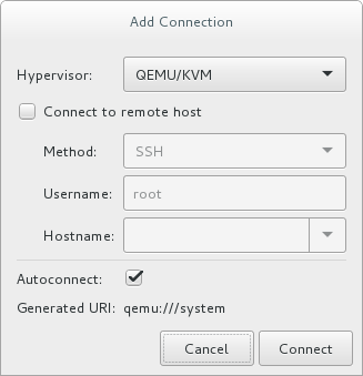
Figure 18.1. Add connection menu
- Use the drop down menu to select hypervisor type, and click the check box to open the Connection (in this case Remote tunnel over SSH), enter the and , then click .
18.3. Remote Management over TLS and SSL
libvirt management connection opens a TCP port for incoming connections, which is securely encrypted and authenticated based on x509 certificates. The following procedures provide instructions on creating and deploying authentication certificates for TLS and SSL management.
Procedure 18.1. Creating a certificate authority (CA) key for TLS management
- Before you begin, confirm that
gnutls-utilsis installed. If not, install it:#
yum install gnutls-utils - Generate a private key, using the following command:
#
certtool --generate-privkey > cakey.pem - After the key is generated, create a signature file so the key can be self-signed. To do this, create a file with signature details and name it
ca.info. This file should contain the following:cn = Name of your organization ca cert_signing_key
- Generate the self-signed key with the following command:
#
certtool --generate-self-signed --load-privkey cakey.pem --template ca.info --outfile cacert.pemAfter the file is generated, theca.infofile can be deleted using thermcommand. The file that results from the generation process is namedcacert.pem. This file is the public key (certificate). The loaded filecakey.pemis the private key. For security purposes, this file should be kept private, and not reside in a shared space. - Install the
cacert.pemCA certificate file on all clients and servers in the/etc/pki/CA/cacert.pemdirectory to let them know that the certificate issued by your CA can be trusted. To view the contents of this file, run:#
certtool -i --infile cacert.pemThis is all that is required to set up your CA. Keep the CA's private key safe, as you will need it in order to issue certificates for your clients and servers.
Procedure 18.2. Issuing a server certificate
qemu://mycommonname/system, so the CN field should be identical, for this example "mycommoname".
- Create a private key for the server.
#
certtool --generate-privkey > serverkey.pem - Generate a signature for the CA's private key by first creating a template file called
server.info. Make sure that the CN is set to be the same as the server's host name:organization = Name of your organization cn = mycommonname tls_www_server encryption_key signing_key
- Create the certificate:
#
certtool --generate-certificate --load-privkey serverkey.pem --load-ca-certificate cacert.pem --load-ca-privkey cakey.pem \ --template server.info --outfile servercert.pemThis results in two files being generated:- serverkey.pem - The server's private key
- servercert.pem - The server's public key
- Make sure to keep the location of the private key secret. To view the contents of the file, use the following command:
#
certtool -i --infile servercert.pemWhen opening this file, theCN=parameter should be the same as the CN that you set earlier. For example,mycommonname. - Install the two files in the following locations:
serverkey.pem- the server's private key. Place this file in the following location:/etc/pki/libvirt/private/serverkey.pemservercert.pem- the server's certificate. Install it in the following location on the server:/etc/pki/libvirt/servercert.pem
Procedure 18.3. Issuing a client certificate
- For every client (that is to say any program linked with libvirt, such as virt-manager), you need to issue a certificate with the X.509 Distinguished Name (DN) field set to a suitable name. This needs to be decided on a corporate level.For example purposes, the following information will be used:
C=USA,ST=North Carolina,L=Raleigh,O=Red Hat,CN=name_of_client
- Create a private key:
#
certtool --generate-privkey > clientkey.pem - Generate a signature for the CA's private key by first creating a template file called
client.info. The file should contain the following (fields should be customized to reflect your region/location):country = USA state = North Carolina locality = Raleigh organization = Red Hat cn = client1 tls_www_client encryption_key signing_key
- Sign the certificate with the following command:
#
certtool --generate-certificate --load-privkey clientkey.pem --load-ca-certificate cacert.pem \ --load-ca-privkey cakey.pem --template client.info --outfile clientcert.pem - Install the certificates on the client machine:
#
cp clientkey.pem /etc/pki/libvirt/private/clientkey.pem#cp clientcert.pem /etc/pki/libvirt/clientcert.pem
18.4. Configuring a VNC Server
devices element of the guest's XML file. For further information, see Section 23.17.11, “Graphical Framebuffers”.
18.5. Enhancing Remote Management of Virtual Machines with NSS
ping.
# yum install libvirt-nssNote
Optional repository for Red Hat Enterprise Linux is enabled. For instructions, see the System Administrator's Guide.
libvirt_guest to the hosts line of the /etc/nsswitch.conf file, for example as follows:
passwd: compat shadow: compat group: compat hosts: files libvirt_guest dns ...
hosts line determines the order in which these modules are consulted to find the specified remote guest. As a result, libvirt's NSS module is added to modules that translate host domain names to IP addresses. This for example enables connecting to a remote guest in NAT mode without setting a static IP address and only using the guest's name:
# ssh root@guestname
root@guestname's password:
Last login: Thu Aug 10 09:12:31 2017 from 192.168.122.1
[root@guestname ~]#
Note
virsh list --all command.
Chapter 19. Managing Guests with the Virtual Machine Manager (virt-manager)
virt-manager) windows, dialog boxes, and various GUI controls.
virt-manager provides a graphical view of hypervisors and guests on your host system and on remote host systems. virt-manager can perform virtualization management tasks, including:
- defining and creating guests,
- assigning memory,
- assigning virtual CPUs,
- monitoring operational performance,
- saving and restoring, pausing and resuming, and shutting down and starting guests,
- links to the textual and graphical consoles, and
- live and offline migrations.
Important
virsh list --all command, it is most likely due to you running the command using a different user than you used to create the virtual machine.
19.1. Starting virt-manager
virt-manager session open the menu, then the menu and select (virt-manager).
virt-manager main window appears.
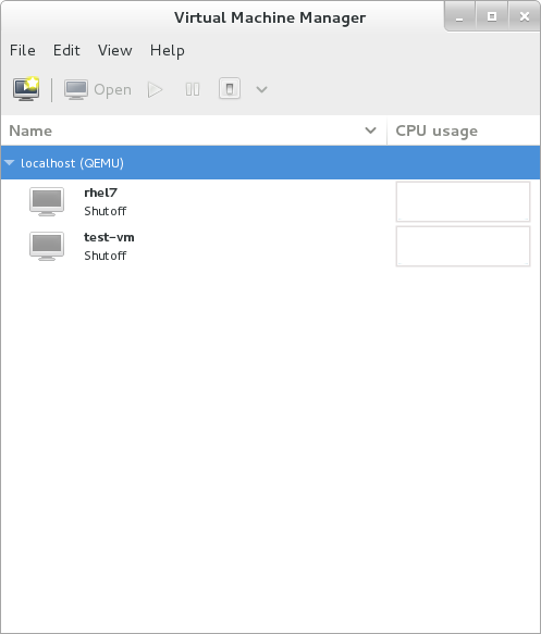
Figure 19.1. Starting virt-manager
virt-manager can be started remotely using ssh as demonstrated in the following command:
#ssh -X host's address[remotehost]#virt-manager
ssh to manage virtual machines and hosts is discussed further in Section 18.2, “Remote Management with SSH”.
19.2. The Virtual Machine Manager Main Window
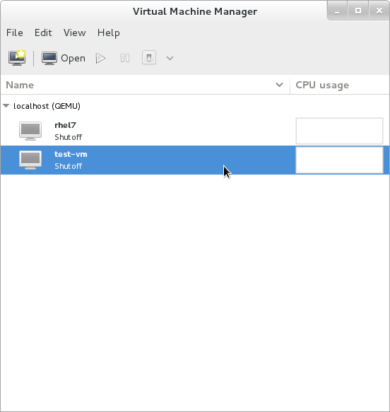
Figure 19.2. Virtual Machine Manager main window
19.3. The Virtual Hardware Details Window

Figure 19.3. The virtual hardware details icon
Figure 19.4. The virtual hardware details window
19.3.1. Applying Boot Options to Guest Virtual Machines
Procedure 19.1. Configuring boot options
- From the Virtual Machine Manager menu, select .
- From the side panel, select and then complete any or all of the following optional steps:
- To indicate that this guest virtual machine should start each time the host physical machine boots, select the check box.
- To indicate the order in which guest virtual machine should boot, click the check box. After this is checked, you can then check the devices you want to boot from and using the arrow keys change the order that the guest virtual machine will use when booting.
- If you want to boot directly from the Linux kernel, expand the menu. Fill in the , , and the that you want to use.
- Click .
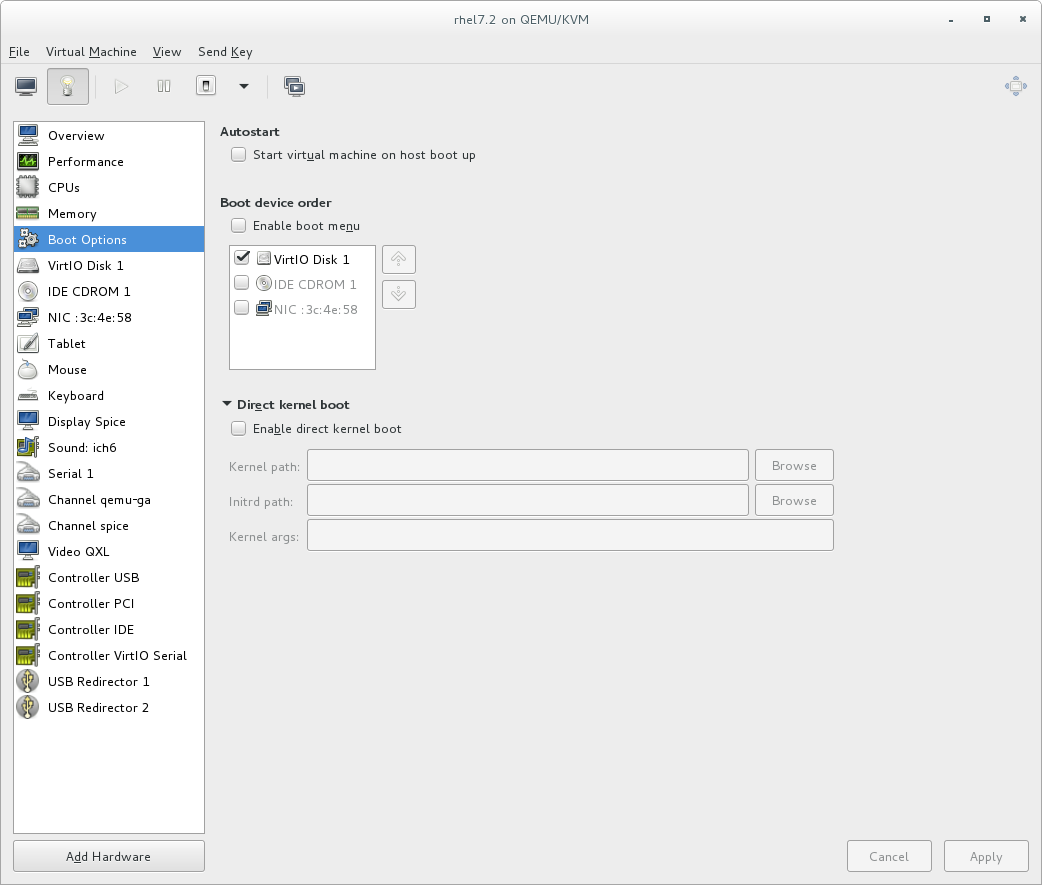
Figure 19.5. Configuring boot options
19.3.2. Attaching USB Devices to a Guest Virtual Machine
Note
Procedure 19.2. Attaching USB devices using Virt-Manager
- Open the guest virtual machine's Virtual Machine Details screen.
- Click
- In the popup, select , select the device you want to attach from the list and Click .
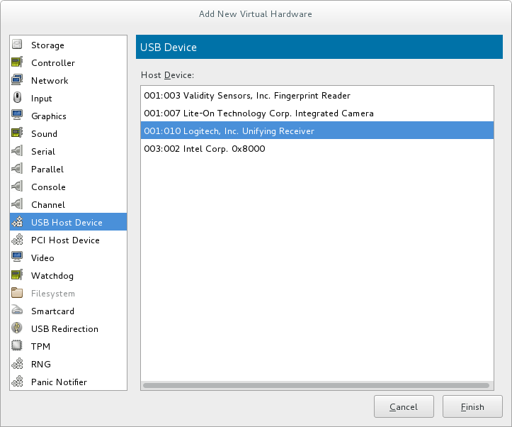
Figure 19.6. Add USB Device
- To use the USB device in the guest virtual machine, start the guest virtual machine.
19.3.3. USB Redirection
Procedure 19.3. Redirecting USB devices
- Open the guest virtual machine's Virtual Machine Details screen.
- Click
- In the popup, select . Make sure to select from the drop-down menu and click .

Figure 19.7. Add New Virtual Hardware window
- Open the menu and select . A pop-up window opens with a list of USB devices.
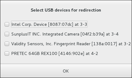
Figure 19.8. Select a USB device
- Select a USB device for redirection by checking its check box and click .
19.4. Virtual Machine Graphical Console
virt-manager supports VNC and SPICE. If your virtual machine is set to require authentication, the Virtual Machine graphical console prompts you for a password before the display appears.
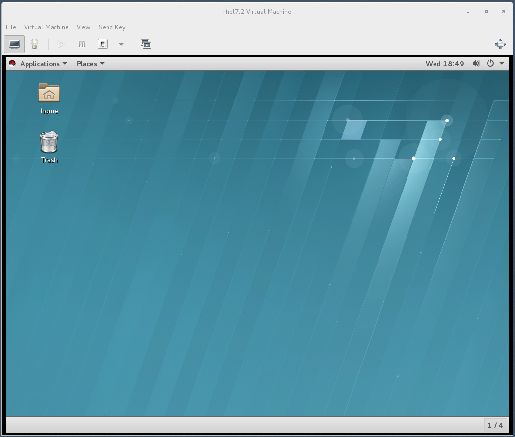
Figure 19.9. Graphical console window
Note
127.0.0.1). This ensures only those with shell privileges on the host can access virt-manager and the virtual machine through VNC. Although virt-manager is configured to listen to other public network interfaces and alternative methods can be configured, it is not recommended.
19.5. Adding a Remote Connection
virt-manager.
- To create a new connection open the File menu and select the Add Connection menu item.
- The Add Connection wizard appears. Select the hypervisor. For Red Hat Enterprise Linux 7, systems select QEMU/KVM. Select Local for the local system or one of the remote connection options and click Connect. This example uses Remote tunnel over SSH, which works on default installations. For more information on configuring remote connections, see Chapter 18, Remote Management of Guests
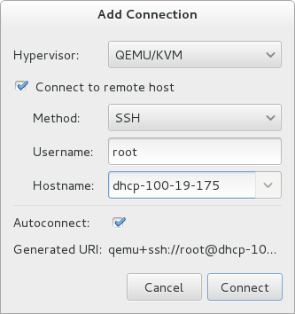
Figure 19.10. Add Connection
- Enter the root password for the selected host when prompted.
virt-manager window.
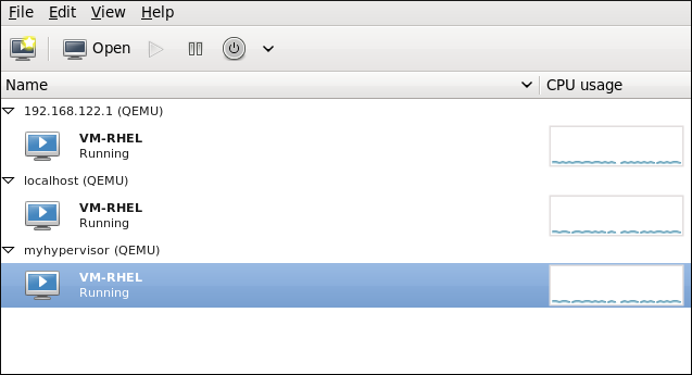
Figure 19.11. Remote host in the main virt-manager window
19.6. Displaying Guest Details
- In the Virtual Machine Manager main window, highlight the virtual machine that you want to view.

Figure 19.12. Selecting a virtual machine to display
- From the Virtual Machine Manager Edit menu, select Virtual Machine Details.When the Virtual Machine details window opens, there may be a console displayed. Should this happen, click View and then select Details. The Overview window opens first by default. To go back to this window, select Overview from the navigation pane on the left-hand side.The Overview view shows a summary of configuration details for the guest.

Figure 19.13. Displaying guest details overview
- Select CPUs from the navigation pane on the left-hand side. The CPUs view allows you to view or change the current processor allocation.It is also possible to increase the number of virtual CPUs (vCPUs) while the virtual machine is running, which is referred to as hot plugging.
Important
Hot unplugging vCPUs is not supported in Red Hat Enterprise Linux 7.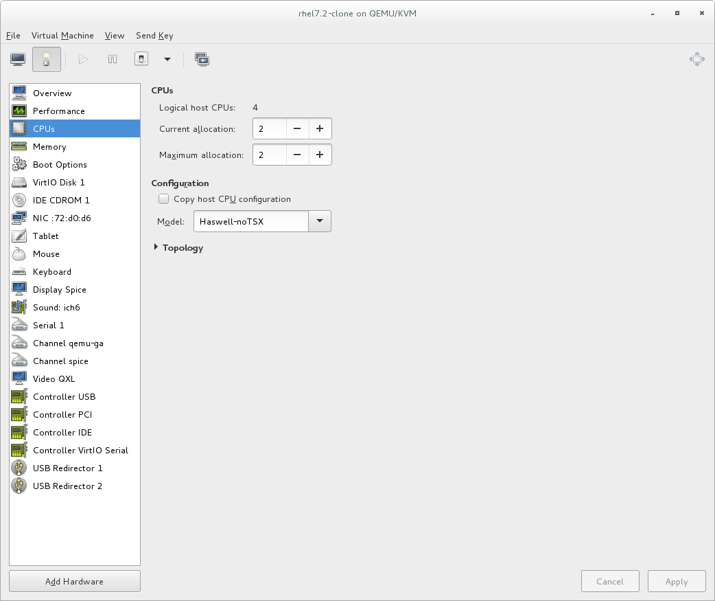
Figure 19.14. Processor allocation panel
- Select Memory from the navigation pane on the left-hand side. The Memory view allows you to view or change the current memory allocation.
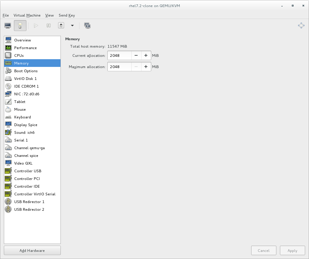
Figure 19.15. Displaying memory allocation
- Select Boot Options from the navigation pane on the left-hand side. The Boot Options view allows you to view or change the boot options including whether or not the virtual machine starts when the host boots and the boot device order for the virtual machine.

Figure 19.16. Displaying boot options
- Each virtual disk attached to the virtual machine is displayed in the navigation pane. click a virtual disk to modify or remove it.

Figure 19.17. Displaying disk configuration
- Each virtual network interface attached to the virtual machine is displayed in the navigation pane. click a virtual network interface to modify or remove it.

Figure 19.18. Displaying network configuration
19.7. Managing Snapshots
Important
virsh snapshot-create-as command with the --diskspec vda,snapshot=external option. For more information, see Section A.13, “Workaround for Creating External Snapshots with libvirt”.
- To manage snapshots in virt-manager, open the snapshot management interface by clicking
 on the guest console.

- To create a new snapshot, click
 under the snapshot list. In the snapshot creation interface, input the name of the snapshot and, optionally, a description, and click .
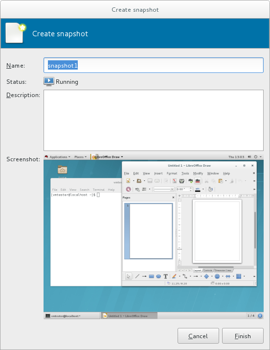
- To revert the guest to a snapshot's configuration, select the snapshot and click
- To remove the selected snapshot, click

Warning
virsh snapshot-create command. See Section 20.39, “Managing Snapshots” for details about managing snapshots with virsh.
Chapter 20. Managing Guest Virtual Machines with virsh
virsh is a command-line interface tool for managing guest virtual machines, and works as the primary means of controlling virtualization on Red Hat Enterprise Linux 7. The virsh command-line tool is built on the libvirt management API, and can be used to create, deploy, and manage guest virtual machines. The virsh utility is ideal for creating virtualization administration scripts, and users without root privileges can use it in read-only mode. The virsh package is installed with yum as part of the libvirt-client package.
virsh command set in a logical order based on usage.
Note
Important
virsh list --all command, it is most likely due to you running the command using a different user than you used to create the virtual machine. See Important for more information.
20.1. Guest Virtual Machine States and Types
virsh commands are affected by the state of the guest virtual machine:
- Transient - A transient guest does not survive reboot.
- Persistent - A persistent guest virtual machine survives reboot and lasts until it is deleted.
- Undefined - This is a guest virtual machine that has not been defined or created. As such, libvirt is unaware of any guest in this state and will not report about guest virtual machines in this state.
- Shut off - This is a guest virtual machine which is defined, but is not running. Only persistent guests can be considered shut off. As such, when a transient guest virtual machine is put into this state, it ceases to exist.
- Running - The guest virtual machine in this state has been defined and is currently working. This state can be used with both persistent and transient guest virtual machines.
- Paused - The guest virtual machine's execution on the hypervisor has been suspended, or its state has been temporarily stored until it is resumed. Guest virtual machines in this state are not aware they have been suspended and do not notice that time has passed when they are resumed.
- Saved - This state is similar to the paused state, however the guest virtual machine's configuration is saved to persistent storage. Any guest virtual machine in this state is not aware it is paused and does not notice that time has passed once it has been restored.
20.2. Displaying the virsh Version
virsh version command displays the current libvirt version and displays information about the local virsh client. For example:
$ virsh version
Compiled against library: libvirt 1.2.8
Using library: libvirt 1.2.8
Using API: QEMU 1.2.8
Running hypervisor: QEMU 1.5.3
virsh version --daemon is useful for getting information about the libvirtd version and package information, including information about the libvirt daemon that is running on the host.
$ virsh version --daemon
Compiled against library: libvirt 1.2.8
Using library: libvirt 1.2.8
Using API: QEMU 1.2.8
Running hypervisor: QEMU 1.5.3
Running against daemon: 1.2.8
20.3. Sending Commands with echo
virsh echo [--shell][--xml] arguments command displays the specified argument in the specified format. The formats you can use are --shell and --xml. Each argument queried is displayed separated by a space. The --shell option generates output that is formatted in single quotes where needed, so it is suitable for copying and pasting into the bash mode as a command. If the --xml argument is used, the output is formatted for use in an XML file, which can then be saved or used for guest's configuration.
20.4. Connecting to the Hypervisor with virsh Connect
virsh connect [hostname-or-URI] [--readonly] command begins a local hypervisor session using virsh. After the first time you run this command it will run automatically each time the virsh shell runs. The hypervisor connection URI specifies how to connect to the hypervisor. The most commonly used URIs are:
qemu:///system- connects locally as the root user to the daemon supervising guest virtual machines on the KVM hypervisor.qemu:///session- connects locally as a user to the user's set of guest local machines using the KVM hypervisor.lxc:///- connects to a local Linux container.
virsh uri command), as shown:
$ virsh uri
qemu:///session$ virsh connect qemu:///session--readonly. For more information on URIs, see Remote URIs. If you are unsure of the URI, the virsh uri command will display it:
20.5. Displaying Information about a Guest Virtual Machine and the Hypervisor
virsh list command will list guest virtual machines connected to your hypervisor that fit the search parameter requested. The output of the command has 3 columns in a table. Each guest virtual machine is listed with its ID, name, and state.
virsh list. These options are available on the man page, by running man virsh or by running the virsh list --help command.
Note
Example 20.1. How to list all locally connected virtual machines
# virsh list --all
Id Name State
------------------------------------------------
8 guest1 running
22 guest2 paused
35 guest3 shut off
38 guest4 shut off
Example 20.2. How to list the inactive guest virtual machines
# virsh list --inactive
Id Name State
------------------------------------------------
35 guest3 shut off
38 guest4 shut off
- #
virsh hostname- displays the hypervisor's host name, for example:#
virsh hostnamedhcp-2-157.eus.myhost.com - #
virsh sysinfo- displays the XML representation of the hypervisor's system information, if available, for example:#
virsh sysinfo<sysinfo type='smbios'> <bios> <entry name='vendor'>LENOVO</entry> <entry name='version'>GJET71WW (2.21 )</entry> [...]
20.6. Starting, Resuming, and Restoring a Virtual Machine
20.6.1. Starting a Guest Virtual Machine
virsh start domain; [--console] [--paused] [--autodestroy] [--bypass-cache] [--force-boot] command starts an inactive virtual machine that was already defined but whose state is inactive since its last managed save state or a fresh boot. By default, if the domain was saved by the virsh managedsave command, the domain will be restored to its previous state. Otherwise, it will be freshly booted. The command can take the following arguments and the name of the virtual machine is required.
--console- will attach the terminal runningvirshto the domain's console device. This is runlevel 3.--paused- if this is supported by the driver, it will start the guest virtual machine in a paused state--autodestroy- the guest virtual machine is automatically destroyed when virsh disconnects--bypass-cache- used if the guest virtual machine is in themanagedsave--force-boot- discards anymanagedsaveoptions and causes a fresh boot to occur
Example 20.3. How to start a virtual machine
# virsh start guest1 --console
Domain guest1 started
Connected to domain guest1
Escape character is ^]
20.6.2. Configuring a Virtual Machine to be Started Automatically at Boot
virsh autostart [--disable] domain command will automatically start the guest virtual machine when the host machine boots. Adding the --disable argument to this command disables autostart. The guest in this case will not start automatically when the host physical machine boots.
Example 20.4. How to make a virtual machine start automatically when the host physical machine starts
# virsh autostart guest120.6.3. Rebooting a Guest Virtual Machine
virsh reboot domain [--mode modename] command. Remember that this action will only return once it has executed the reboot, so there may be a time lapse from that point until the guest virtual machine actually reboots. You can control the behavior of the rebooting guest virtual machine by modifying the on_reboot element in the guest virtual machine's XML configuration file. By default, the hypervisor attempts to select a suitable shutdown method automatically. To specify an alternative method, the --mode argument can specify a comma separated list which includes acpi and agent. The order in which drivers will try each mode is undefined, and not related to the order specified in virsh. For strict control over ordering, use a single mode at a time and repeat the command.
Example 20.5. How to reboot a guest virtual machine
initctl method, but you can choose any mode that suits your needs.
# virsh reboot guest1 --mode initctl20.6.4. Restoring a Guest Virtual Machine
virsh restore <file> [--bypass-cache] [--xml /path/to/file] [--running] [--paused] command restores a guest virtual machine previously saved with the virsh save command. See Section 20.7.1, “Saving a Guest Virtual Machine's Configuration” for information on the virsh save command. The restore action restarts the saved guest virtual machine, which may take some time. The guest virtual machine's name and UUID are preserved, but the ID will not necessarily match the ID that the virtual machine had when it was saved.
virsh restore command can take the following arguments:
--bypass-cache- causes the restore to avoid the file system cache but note that using this flag may slow down the restore operation.--xml- this argument must be used with an XML file name. Although this argument is usually omitted, it can be used to supply an alternative XML file for use on a restored guest virtual machine with changes only in the host-specific portions of the domain XML. For example, it can be used to account for the file naming differences in underlying storage due to disk snapshots taken after the guest was saved.--running- overrides the state recorded in the save image to start the guest virtual machine as running.--paused- overrides the state recorded in the save image to start the guest virtual machine as paused.
Example 20.6. How to restore a guest virtual machine
# virsh restore guest1-config.xml --running20.6.5. Resuming a Guest Virtual Machine
virsh resume domain command restarts the CPUs of a domain that was suspended. This operation is immediate. The guest virtual machine resumes execution from the point it was suspended. Note that this action will not resume a guest virtual machine that has been undefined. This action will not resume transient virtual machines and will only work on persistent virtual machines.
Example 20.7. How to restore a suspended guest virtual machine
# virsh resume guest120.7. Managing a Virtual Machine Configuration
20.7.1. Saving a Guest Virtual Machine's Configuration
virsh save [--bypass-cache] domain file [--xml string] [--running] [--paused] [--verbose] command stops the specified domain, saving the current state of the guest virtual machine's system memory to a specified file. This may take a considerable amount of time, depending on the amount of memory in use by the guest virtual machine. You can restore the state of the guest virtual machine with the virsh restore (Section 20.6.4, “Restoring a Guest Virtual Machine”) command.
virsh save command and the virsh suspend command, is that the virsh suspend stops the domain CPUs, but leaves the domain's qemu process running and its memory image resident in the host system. This memory image will be lost if the host system is rebooted.
virsh save command stores the state of the domain on the hard disk of the host system and terminates the qemu process. This enables restarting the domain from the saved state.
virsh save with the virsh domjobinfo command and cancel it with the virsh domjobabort command.
virsh save command can take the following arguments:
--bypass-cache- causes the restore to avoid the file system cache but note that using this flag may slow down the restore operation.--xml- this argument must be used with an XML file name. Although this argument is usually omitted, it can be used to supply an alternative XML file for use on a restored guest virtual machine with changes only in the host-specific portions of the domain XML. For example, it can be used to account for the file naming differences in underlying storage due to disk snapshots taken after the guest was saved.--running- overrides the state recorded in the save image to start the guest virtual machine as running.--paused- overrides the state recorded in the save image to start the guest virtual machine as paused.--verbose- displays the progress of the save.
Example 20.8. How to save a guest virtual machine running configuration
guest1-config.xml file:
# virsh save guest1 guest1-config.xml --running20.7.2. Defining a Guest Virtual Machine with an XML File
virsh define filename command defines a guest virtual machine from an XML file. The guest virtual machine definition in this case is registered but not started. If the guest virtual machine is already running, the changes the changes will take effect once the domain is shut down and started again.
Example 20.9. How to create a guest virtual machine from an XML file
# virsh define guest1-config.xml20.7.3. Updating the XML File That will be Used for Restoring a Guest Virtual Machine
Note
virsh save-image-define filename [--xml /path/to/file] [--running] [--paused] command updates the guest virtual machine's XML file that will be used when the virtual machine is restored used during the virsh restore command. The --xml argument must be an XML file name containing the alternative XML elements for the guest virtual machine's XML. For example, it can be used to account for the file naming differences resulting from creating disk snapshots of underlying storage after the guest was saved. The save image records if the guest virtual machine should be restored to a running or paused state. Using the arguments --running or --paused dictates the state that is to be used.
Example 20.10. How to save the guest virtual machine's running configuration
# virsh save-image-define guest1-config.xml --running20.7.4. Extracting the Guest Virtual Machine XML File
Note
virsh save-image-dumpxml file --security-info command will extract the guest virtual machine XML file that was in effect at the time the saved state file (used in the virsh save command) was referenced. Using the --security-info argument includes security sensitive information in the file.
Example 20.11. How to pull the XML configuration from the last save
# virsh save-image-dumpxml guest1-config.xml20.7.5. Editing the Guest Virtual Machine Configuration
Note
virsh save-image-edit <file> [--running] [--paused] command edits the XML configuration file that was created by the virsh save command. See Section 20.7.1, “Saving a Guest Virtual Machine's Configuration” for information on the virsh save command.
--running or --paused state. Without using these arguments in the save-image-edit command, the state is determined by the image file itself. By selecting --running (to select the running state) or --paused (to select the paused state) you can overwrite the state that virsh restore should use.
Example 20.12. How to edit a guest virtual machine's configuration and restore the machine to running state
# virsh save-image-edit guest1-config.xml --running20.8. Shutting off, Shutting down, Rebooting, and Forcing a Shutdown of a Guest Virtual Machine
20.8.1. Shutting down a Guest Virtual Machine
virsh shutdown domain [--mode modename] command shuts down a guest virtual machine. You can control the behavior of how the guest virtual machine reboots by modifying the on_shutdown parameter in the guest virtual machine's configuration file. Any change to the on_shutdown parameter will only take effect after the domain has been shutdown and restarted.
virsh shutdown command command can take the following optional argument:
--modechooses the shutdown mode. This can be eitheracpi,agent,initctl,signal, orparavirt.
Example 20.13. How to shutdown a guest virtual machine
acpi mode:
# virsh shutdown guest1 --mode acpi
Domain guest1 is being shutdown
20.8.2. Suspending a Guest Virtual Machine
virsh suspend domain command suspends a guest virtual machine.
virsh resume command. Running this command on a transient virtual machine will delete it.
Example 20.14. How to suspend a guest virtual machine
# virsh suspend guest120.8.3. Resetting a Virtual Machine
virsh reset domain resets the guest virtual machine immediately without any guest shutdown. A reset emulates the reset button on a machine, where all guest hardware sees the RST line and re-initializes the internal state. Note that without any guest virtual machine OS shutdown, there are risks for data loss.
Note
Example 20.15. How to reset a guest virtual machine
# virsh reset guest120.8.4. Stopping a Running Guest Virtual Machine in Order to Restart It Later
virsh managedsave domain --bypass-cache --running | --paused | --verbose command saves and destroys (stops) a running guest virtual machine so that it can be restarted from the same state at a later time. When used with a virsh start command it is automatically started from this save point. If it is used with the --bypass-cache argument the save will avoid the filesystem cache. Note that this option may slow down the save process speed and using the --verbose option displays the progress of the dump process. Under normal conditions, the managed save will decide between using the running or paused state as determined by the state the guest virtual machine is in when the save is done. However, this can be overridden by using the --running option to indicate that it must be left in a running state or by using --paused option which indicates it is to be left in a paused state. To remove the managed save state, use the virsh managedsave-remove command which will force the guest virtual machine to do a full boot the next time it is started. Note that the entire managed save process can be monitored using the domjobinfo command and can also be canceled using the domjobabort command.
Example 20.16. How to stop a running guest and save its configuration
# virsh managedsave guest1 --running20.9. Removing and Deleting a Virtual Machine
20.9.1. Undefining a Virtual Machine
virsh undefine domain [--managed-save] [storage] [--remove-all-storage] [--wipe-storage] [--snapshots-metadata] [--nvram] command undefines a domain. If domain is inactive, the configuration is removed completely. If the domain is active (running), it is converted to a transient domain. When the guest virtual machine becomes inactive, the configuration is removed completely.
--managed-save- this argument guarantees that any managed save image is also cleaned up. Without using this argument, attempts to undefine a guest virtual machine with a managed save will fail.--snapshots-metadata- this argument guarantees that any snapshots (as shown withsnapshot-list) are also cleaned up when undefining an inactive guest virtual machine. Note that any attempts to undefine an inactive guest virtual machine with snapshot metadata will fail. If this argument is used and the guest virtual machine is active, it is ignored.--storage- using this argument requires a comma separated list of volume target names or source paths of storage volumes to be removed along with the undefined domain. This action will undefine the storage volume before it is removed. Note that this can only be done with inactive guest virtual machines and that this will only work with storage volumes that are managed by libvirt.--remove-all-storage- in addition to undefining the guest virtual machine, all associated storage volumes are deleted. If you want to delete the virtual machine, choose this option only if there are no other virtual machines using the same associated storage. An alternative way is with thevirsh vol-delete. See Section 20.31, “Deleting Storage Volumes” for more information.--wipe-storage- in addition to deleting the storage volume, the contents are wiped.
Example 20.17. How to delete a guest virtual machine and delete its storage volumes
# virsh undefine guest1 --remove-all-storage20.9.2. Forcing a Guest Virtual Machine to Stop
Note
virsh destroy command initiates an immediate ungraceful shutdown and stops the specified guest virtual machine. Using virsh destroy can corrupt guest virtual machine file systems. Use the virsh destroy command only when the guest virtual machine is unresponsive. The virsh destroy command with the --graceful option attempts to flush the cache for the disk image file before powering off the virtual machine.
Example 20.18. How to immediately shutdown a guest virtual machine with a hard shutdown
# virsh destroy guest1virsh undefine command. See Example 20.17, “How to delete a guest virtual machine and delete its storage volumes”
20.10. Connecting the Serial Console for the Guest Virtual Machine
virsh console domain [--devname devicename] [--force] [--safe] command connects the virtual serial console for the guest virtual machine. This is very useful for example for guests that do not provide VNC or SPICE protocols (and thus does not offer video display for GUI tools) and that do not have network connection (and thus cannot be interacted with using SSH).
--devname parameter refers to the device alias of an alternate console, serial, or parallel device configured for the guest virtual machine. If this parameter is omitted, the primary console will be opened. If the --safe option is specified, the connection is only attempted if the driver supports safe console handling. This option specifies that the server has to ensure exclusive access to console devices. Optionally, the force option may be specified, which requests to disconnect any existing sessions, such as in the case of a broken connection.
Example 20.19. How to start a guest virtual machine in console mode
# virsh console guest1 --safe20.11. Injecting Non-maskable Interrupts
virsh inject-nmi domain injects a non-maskable interrupt (NMI) message to the guest virtual machine. This is used when response time is critical, such as during non-recoverable hardware errors. In addition, virsh inject-nmi is useful for triggering a crashdump in Windows guests.
Example 20.20. How to inject an NMI to the guest virtual machine
# virsh inject-nmi guest120.12. Retrieving Information about Your Virtual Machine
20.12.1. Displaying Device Block Statistics
virsh domblkstat command displays the block statistics for the first block device defined for the domain. To view statistics of other block devices, use the virsh domblklist domain command to list all block devices, and then select a specific block device and display it by specifying either the Target or Source name from the virsh domblklist command output after the domain name. Note that not every hypervisor can display every field. To make sure that the output is presented in its most legible form use the --human argument.
Example 20.21. How to display block statistics for a guest virtual machine
#virsh domblklist guest1Target Source ------------------------------------------------ vda /VirtualMachines/guest1.img hdc - #virsh domblkstat guest1 vda --humanDevice: vda number of read operations: 174670 number of bytes read: 3219440128 number of write operations: 23897 number of bytes written: 164849664 number of flush operations: 11577 total duration of reads (ns): 1005410244506 total duration of writes (ns): 1085306686457 total duration of flushes (ns): 340645193294
20.12.2. Retrieving Network Interface Statistics
virsh domifstat domain interface-device command displays the network interface statistics for the specified device running on a given guest virtual machine.
virsh domiflist command and use the output in the Interface column.
Example 20.22. How to display networking statistics for a guest virtual machine
#virsh domiflist guest1Interface Type Source Model MAC ------------------------------------------------------- macvtap0 direct em1 rtl8139 12:34:00:0f:8a:4a #virsh domifstat guest1 macvtap0macvtap0 rx_bytes 51120 macvtap0 rx_packets 440 macvtap0 rx_errs 0 macvtap0 rx_drop 0 macvtap0 tx_bytes 231666 macvtap0 tx_packets 520 macvtap0 tx_errs 0 macvtap0 tx_drop 0
20.12.3. Modifying the Link State of a Guest Virtual Machine's Virtual Interface
virsh domif-setlink domain interface-device state command configures the status of the specified interface device link state as either up or down. To determine which interface devices are defined for the domain, use the virsh domiflist command and use either the Interface or MAC column as the interface device option. By default, virsh domif-setlink changes the link state for the running domain. To modify the domain's persistent configuration use the --config argument.
Example 20.23. How to enable a guest virtual machine interface
# virsh domiflist rhel7Interface Type Source Model MAC ------------------------------------------------------- vnet0 network default virtio 52:54:00:01:1d:d0 #virsh domif-setlink rhel7 vnet0 downDevice updated successfully #virsh domif-setlink rhel7 52:54:00:01:1d:d0 upDevice updated successfully
20.12.4. Listing the Link State of a Guest Virtual Machine's Virtual Interface
virsh domif-getlink domain interface-device command retrieves the specified interface device link state. To determine which interface devices are defined for the domain, use the virsh domiflist command and use either the Interface or MAC column as the interface device option. By default, virsh domif-getlink retrieves the link state for the running domain. To retrieve the domain's persistent configuration use the --config option.
Example 20.24. How to display the link state of a guest virtual machine's interface
#virsh domiflist rhel7Interface Type Source Model MAC ------------------------------------------------------- vnet0 network default virtio 52:54:00:01:1d:d0 #virsh domif-getlink rhel7 52:54:00:01:1d:d052:54:00:01:1d:d0 up #virsh domif-setlink rhel7 vnet0 downDevice updated successfully #virsh domif-getlink rhel7 vnet0vnet0 down
20.12.5. Setting Network Interface Bandwidth Parameters
virsh domiftune domain interface-device command either retrieves or sets the specified domain's interface bandwidth parameters. To determine which interface devices are defined for the domain, use the virsh domiflist command and use either the Interface or MAC column as the interface device option. The following format should be used:
# virsh domiftune domain interface [--inbound] [--outbound] [--config] [--live] [--current]--config, --live, and --current options are described in Section 20.43, “Setting Schedule Parameters”. If the --inbound or the --outbound option is not specified, virsh domiftune queries the specified network interface and displays the bandwidth settings. By specifying --inbound or --outbound, or both, and the average, peak, and burst values, virsh domiftune sets the bandwidth settings. At minimum the average value is required. In order to clear the bandwidth settings, provide 0 (zero). For a description of the average, peak, and burst values, see Section 20.27.6.2, “Attaching interface devices”.
Example 20.25. How to set the guest virtual machine network interface parameters
# virsh domiftune guest1 eth0 outbound --live20.12.6. Retrieving Memory Statistics
virsh dommemstat domain [<period in seconds>] [--config] [--live] [--current] command displays the memory statistics for a running guest virtual machine. Using the optional period switch requires a time period in seconds. Setting this option to a value larger than 0 will allow the balloon driver to return additional statistics which will be displayed by running subsequent dommemstat commands. Setting the period option to 0, stops the balloon driver collection but does not clear the statistics already in the balloon driver. You cannot use the --live, --config, or --current options without also setting the period option. If the --live option is specified, only the guest's running statistics will be collected. If the --config option is used, it will collect the statistics for a persistent guest, but only after the next boot. If the --current option is used, it will collect the current statistics.
--live and --config options may be used but --current is exclusive. If no flag is specified, the guest's state will dictate the behavior of the statistics collection (running or not).
Example 20.26. How to collect memory statistics for a running guest virtual machine
# virsh dommemstat rhel7
actual 1048576
swap_in 0
swap_out 0
major_fault 2974
minor_fault 1272454
unused 246020
available 1011248
rss 865172
20.12.7. Displaying Errors on Block Devices
virsh domblkerror domain command lists all the block devices in the error state and the error detected on each of them. This command is best used after a virsh domstate command reports that a guest virtual machine is paused due to an I/O error.
Example 20.27. How to display the block device errors for a virtual machine
# virsh domblkerror guest120.12.8. Displaying the Block Device Size
virsh domblkinfo domain command lists the capacity, allocation, and physical block sizes for a specific block device in the virtual machine. Use the virsh domblklist command to list all block devices and then choose to display a specific block device by specifying either the Target or Source name from the virsh domblklist output after the domain name.
Example 20.28. How to display the block device size
#virsh domblklist rhel7Target Source ------------------------------------------------ vda /home/vm-images/rhel7-os vdb /home/vm-images/rhel7-data #virsh domblkinfo rhel7 vdaCapacity: 10737418240 Allocation: 8211980288 Physical: 10737418240 #virsh domblkinfo rhel7 /home/vm-images/rhel7-dataCapacity: 104857600 Allocation: 104857600 Physical: 104857600
20.12.9. Displaying the Block Devices Associated with a Guest Virtual Machine
virsh domblklist domain [--inactive] [--details] command displays a table of all block devices that are associated with the specified guest virtual machine.
--inactive is specified, the result will show the devices that are to be used at the next boot and will not show those that are currently running in use by the running guest virtual machine. If --details is specified, the disk type and device value will be included in the table. The information displayed in this table can be used with other commands that require a block-device to be provided, such as virsh domblkinfo and virsh snapshot-create. The disk Target or Source contexts can also be used when generating the xmlfile context information for the virsh snapshot-create command.
Example 20.29. How to display the block devices that are associated with a virtual machine
# virsh domblklist rhel7 --details
Type Device Target Source
------------------------------------------------
file disk vda /home/vm-images/rhel7-os
file disk vdb /home/vm-images/rhel7-data
20.12.10. Displaying Virtual Interfaces Associated with a Guest Virtual Machine
virsh domblklist domain command displays a table of all the virtual interfaces that are associated with the specified domain. The virsh domiflist command requires the name of the virtual machine (or domain), and optionally can take the --inactive argument. The latter retrieves the inactive rather than the running configuration, which is retrieved with the default setting. If --inactive is specified, the result shows devices that are to be used at the next boot, and does not show devices that are currently in use by the running guest. Virsh commands that require a MAC address of a virtual interface (such as detach-interface, domif-setlink, domif-getlink, domifstat, and domiftune) accept the output displayed by this command.
Example 20.30. How to display the virtual interfaces associated with a guest virtual machine
#virsh domiflist rhel7Interface Type Source Model MAC ------------------------------------------------------- vnet0 network default virtio 52:54:00:01:1d:d0 #virsh domifstat rhel7 vnet0vnet0 rx_bytes 55308 vnet0 rx_packets 969 vnet0 rx_errs 0 vnet0 rx_drop 0 vnet0 tx_bytes 14341 vnet0 tx_packets 148 vnet0 tx_errs 0 vnet0 tx_drop 0
20.13. Working with Snapshots
20.13.1. Shortening a Backing Chain by Copying the Data
virsh blockcommit domain <path> [<bandwidth>] [<base>] [--shallow] [<top>] [--active] [--delete] [--wait] [--verbose] [--timeout <number>] [--pivot] [--keep-overlay] [--async] [--keep-relative] command to shorten a backing chain. The command has many options, which are listed in the help menu or man page.
virsh blockcommit command copies data from one part of the chain down into a backing file, allowing you to pivot the rest of the chain in order to bypass the committed portions. For example, suppose this is the current state:
base ← snap1 ← snap2 ← active.
virsh blockcommit moves the contents of snap2 into snap1, allowing you to delete snap2 from the chain, making backups much quicker.
Procedure 20.1. How to shorten a backing chain
- Enter the following command, replacing guest1 with the name of your guest virtual machine and disk1 with the name of your disk.
#
virsh blockcommit guest1 disk1 --base snap1 --top snap2--wait--verboseThe contents of snap2 are moved into snap1, resulting in:base ← snap1 ← active. Snap2 is no longer valid and can be deletedWarning
virsh blockcommitwill corrupt any file that depends on the--baseargument (other than files that depended on the--topargument, as those files now point to the base). To prevent this, do not commit changes into files shared by more than one guest. The--verboseoption will allow the progress to be printed on the screen.
20.13.2. Shortening a Backing Chain by Flattening the Image
virsh blockpull can be used in in the following applications:
- Flattens an image by populating it with data from its backing image chain. This makes the image file self-contained so that it no longer depends on backing images and looks like this:
- Before: base.img ← active
- After: base.img is no longer used by the guest and Active contains all of the data.
- Flattens part of the backing image chain. This can be used to flatten snapshots into the top-level image and looks like this:
- Before: base ← sn1 ←sn2 ← active
- After: base.img ← active. Note that active now contains all data from sn1 and sn2, and neither sn1 nor sn2 are used by the guest.
- Moves the disk image to a new file system on the host. This is allows image files to be moved while the guest is running and looks like this:
- Before (The original image file):
/fs1/base.vm.img - After:
/fs2/active.vm.qcow2is now the new file system and/fs1/base.vm.imgis no longer used.
- Useful in live migration with post-copy storage migration. The disk image is copied from the source host to the destination host after live migration completes.In short this is what happens: Before:
/source-host/base.vm.imgAfter:/destination-host/active.vm.qcow2./source-host/base.vm.imgis no longer used.
Procedure 20.2. How to shorten a backing chain by flattening the data
- It may be helpful to create a snapshot prior to running
virsh blockpull. To do so, use thevirsh snapshot-create-ascommand. In the following example, replace guest1 with the name of your guest virtual machine, and snap1 with the name of your snapshot.#
virsh snapshot-create-as guest1 snap1--disk-only - If the chain looks like this:
base ← snap1 ← snap2 ← active, enter the following command, replacing guest1 with the name of your guest virtual machine and path1 with the source path to your disk (/home/username/VirtualMachines/*, for example).#
virsh blockpull guest1 path1This command makes snap1 the backing file of active, by pulling data from snap2 into active resulting in:base ← snap1 ← active. - Once the
virsh blockpullis complete, the libvirt tracking of the snapshot that created the extra image in the chain is no longer useful. Delete the tracking on the outdated snapshot with this command, replacing guest1 with the name of your guest virtual machine and snap1 with the name of your snapshot.#
virsh snapshot-delete guest1 snap1 --metadata
virsh blockpull can be performed as follows:
Example 20.31. How to flatten a single image and populate it with data from its backing image chain
# virsh blockpull guest1 vda --wait
Example 20.32. How to flatten part of the backing image chain
# virsh blockpull guest1 vda /path/to/base.img --base --waitExample 20.33. How to move the disk image to a new file system on the host
# virsh snapshot-create guest1 --xmlfile /path/to/snap1.xml --disk-only# virsh blockpull guest1 disk1 --waitExample 20.34. How to use live migration with post-copy storage migration
# qemu-img create -f qcow2 -o backing_file=/source-host/vm.img /destination-host/vm.qcow2# virsh migrate guest1# virsh blockpull guest1 disk1 --wait20.13.3. Changing the Size of a Guest Virtual Machine's Block Device
virsh blockresize command can be used to resize a block device of a guest virtual machine while the guest virtual machine is running, using the absolute path of the block device, which also corresponds to a unique target name (<target dev="name"/>) or source file (<source file="name"/>). This can be applied to one of the disk devices attached to guest virtual machine (you can use the command virsh domblklist to print a table showing the brief information of all block devices associated with a given guest virtual machine).
Note
echo > /sys/class/scsi_device/0:0:0:0/device/rescan. In addition, with IDE it is required to reboot the guest before it picks up the new size.
Example 20.35. How to resize the guest virtual machine block device
# virsh blockresize guest1 90 B20.14. Displaying a URI for Connection to a Graphical Display
virsh domdisplay command will output a URI that can then be used to connect to the graphical display of the guest virtual machine via VNC, SPICE, or RDP. The optional --type can be used to specify the graphical display type. If the argument --include-password is used, the SPICE channel password will be included in the URI.
Example 20.36. How to display the URI for SPICE
# virsh domdisplay --type spice guest1
spice://192.0.2.1:5900
20.15. Displaying the IP Address and Port Number for the VNC Display
virsh vncdisplay command returns the IP address and port number of the VNC display for the specified guest virtual machine. If the information is unavailable for the guest, the exit code 1 is displayed.
devices element of the guest's XML file. For further information, see Section 23.17.11, “Graphical Framebuffers”.
Example 20.37. How to display the IP address and port number for VNC
# virsh vncdisplay guest1
127.0.0.1:0
20.16. Discarding Blocks Not in Use
virsh domfstrim domain [--minimum bytes] [--mountpoint mountPoint] command invokes the fstrim utility on all mounted file systems within a specified running guest virtual machine. This discards blocks not in use by the file system. If the argument --minimum is used, an amount in bytes must be specified. This amount will be sent to the guest kernel as its length of contiguous free range. Values smaller than this amount may be ignored. Increasing this value will create competition with file systems with badly fragmented free space. Note that not all blocks in this case are discarded. The default minimum is zero which means that every free block is discarded. If you increase this value to greater than zero, the fstrim operation will complete more quickly for file systems with badly fragmented free space, although not all blocks will be discarded. If a user only wants to trim one specific mount point, the --mountpoint argument should be used and a mount point should be specified.
Example 20.38. How to discard blocks not in use
# virsh domfstrim guest1 --minimum 020.17. Guest Virtual Machine Retrieval Commands
20.17.1. Displaying the Host Physical Machine Name
virsh domhostname domain command displays the specified guest virtual machine's physical host name provided the hypervisor can publish it.
Example 20.39. How to display the host physical machine name
# virsh domhostname guest120.17.2. Displaying General Information about a Virtual Machine
virsh dominfo domain command displays basic information about a specified guest virtual machine. This command may also be used with the option [--domain] guestname.
Example 20.40. How to display general information about the guest virtual machine
# virsh dominfo guest1
Id: 8
Name: guest1
UUID: 90e0d63e-d5c1-4735-91f6-20a32ca22c40
OS Type: hvm
State: running
CPU(s): 1
CPU time: 271.9s
Max memory: 1048576 KiB
Used memory: 1048576 KiB
Persistent: yes
Autostart: disable
Managed save: no
Security model: selinux
Security DOI: 0
Security label: system_u:system_r:svirt_t:s0:c422,c469 (enforcing)
20.17.3. Displaying a Virtual Machine's ID Number
virsh list includes the ID in its output, the virsh domid domain>|<ID displays the ID for the guest virtual machine, provided it is running. An ID will change each time you run the virtual machine. If guest virtual machine is shut off, the machine name will be displayed as a series of dashes ('-----'). This command may also be used with the [--domain guestname] option.
Example 20.41. How to display a virtual machine's ID number
# virsh domid guest1
8
20.17.4. Aborting Running Jobs on a Guest Virtual Machine
virsh domjobabort domain command aborts the currently running job on the specified guest virtual machine. This command may also be used with the [--domain guestname] option.
Example 20.42. How to abort a running job on a guest virtual machine
# virsh domjobabort guest120.17.5. Displaying Information about Jobs Running on the Guest Virtual Machine
virsh domjobinfo domain command displays information about jobs running on the specified guest virtual machine, including migration statistics. This command may also be used with the [--domain guestname] option, or with the --completed option to return information on the statistics of a recently completed job.
Example 20.43. How to display statistical feedback
# virsh domjobinfo guest1
Job type: Unbounded
Time elapsed: 1603 ms
Data processed: 47.004 MiB
Data remaining: 658.633 MiB
Data total: 1.125 GiB
Memory processed: 47.004 MiB
Memory remaining: 658.633 MiB
Memory total: 1.125 GiB
Constant pages: 114382
Normal pages: 12005
Normal data: 46.895 MiB
Expected downtime: 0 ms
Compression cache: 64.000 MiB
Compressed data: 0.000 B
Compressed pages: 0
Compression cache misses: 12005
Compression overflows: 0
20.17.6. Displaying the Guest Virtual Machine's Name
virsh domname domainID command displays the name guest virtual machine name, given its ID or UUID. Although the virsh list --all command will also display the guest virtual machine's name, this command only lists the guest's name.
Example 20.44. How to display the name of the guest virtual machine
# virsh domname 8
guest1
20.17.7. Displaying the Virtual Machine's State
virsh domstate domain command displays the state of the given guest virtual machine. Using the --reason argument will also display the reason for the displayed state. This command may also be used with the [--domain guestname] option, as well as the --reason option, which displays the reason for the state. If the command reveals an error, you should run the command virsh domblkerror. See Section 20.12.7, “Displaying Errors on Block Devices” for more details.
Example 20.45. How to display the guest virtual machine's current state
# virsh domstate guest1
running
20.17.8. Displaying the Connection State to the Virtual Machine
virsh domcontrol domain displays the state of an interface to the hypervisor that is used to control a specified guest virtual machine. For states that are not OK or Error, it will also print the number of seconds that have elapsed since the control interface entered the displayed state.
Example 20.46. How to display the guest virtual machine's interface state
# virsh domcontrol guest1
ok
20.18. Converting QEMU Arguments to Domain XML
virsh domxml-from-native command provides a way to convert an existing set of QEMU arguments into a Domain XML configuration file that can then be used by libvirt. Note that this command is intended to be used only to convert existing QEMU guests previously started from the command line, in order to enable them to be managed through libvirt. Therefore, the method described here should not be used to create new guests from scratch. New guests should be created using either virsh, virt-install, or virt-manager. Additional information can be found on the libvirt upstream website.
Procedure 20.3. How to convert a QEMU guest to libvirt
- Start with a QEMU guest with a arguments file (file type
*.args), named demo.args in this example:$
cat demo.argsLC_ALL=C PATH=/bin HOME=/home/test USER=test LOGNAME=test /usr/bin/qemu -S -M pc -m 214 -smp 1 -nographic -monitor pty -no-acpi -boot c -hda /dev/HostVG/QEMUGuest1 -net none -serial none -parallel none -usb - To convert this file into a domain XML file so that the guest can be managed by libvirt, enter the following command. Remember to replace qemu-guest1 with the name of your guest virtual machine and demo.args with the filename of your QEMU args file.
#
virsh domxml-from-native qemu-guest1demo.argsThis command turns the demo.args file into the following domain XML file:<domain type='qemu'> <uuid>00000000-0000-0000-0000-000000000000</uuid> <memory>219136</memory> <currentMemory>219136</currentMemory> <vcpu>1</vcpu> <os> <type arch='i686' machine='pc'>hvm</type> <boot dev='hd'/> </os> <clock offset='utc'/> <on_poweroff>destroy</on_poweroff> <on_reboot>restart</on_reboot> <on_crash>destroy</on_crash> <devices> <emulator>/usr/bin/qemu</emulator> <disk type='block' device='disk'> <source dev='/dev/HostVG/QEMUGuest1'/> <target dev='hda' bus='ide'/> </disk> </devices> </domain>Figure 20.1. Guest virtual machine new configuration file
20.19. Creating a Dump File of a Guest Virtual Machine's Core Using virsh dump
virsh dump domain corefilepath [--bypass-cache] {--live | --crash | --reset} [--verbose] [--memory-only] [--format=format] command. This creates a dump file containing the core of the guest virtual machine so that it can be analyzed, for example by the crash utility.
virsh dump command dumps the guest virtual machine core to a file specified by the core file path that you supply. Note that some hypervisors may give restrictions on this action and may require the user to manually ensure proper permissions on the file and path specified in the corefilepath parameter. This command is supported with SR-IOV devices as well as other passthrough devices. The following arguments are supported and have the following effect:
--bypass-cache- The file saved will not bypass the host's file system cache. It has no effect on the content of the file. Note that selecting this option may slow down the dump operation.--livewill save the file as the guest virtual machine continues to run and will not pause or stop the guest virtual machine.--crashputs the guest virtual machine in a crashed status rather than leaving it in a paused state while the dump file is saved. The guest virtual machine will be listed as "Shut off", with the reason as "Crashed".--reset- When the dump file is successfully saved, the guest virtual machine will reset.--verbosedisplays the progress of the dump process--memory-only- Running a dump using this option will create a dump file where the contents of the dump file will only contain the guest virtual machine's memory and CPU common register file. This option should be used in cases where running a full dump will fail. This may happen when a guest virtual machine cannot be live migrated (due to a passthrough PCI device).You can save the memory-only dump using the--format=formatoption. The following formats are available:elf- the default, uncompressed formatkdump-zlib- kdump-compressed format with zlib compressionkdump-lzo- kdump-compressed format with LZO compressionkdump-snappy- kdump-compressed format with Snappy compression
Important
Thecrashutility no longer supports the default core dump file format of thevirsh dumpcommand. If you usecrashto analyze a core dump file created byvirsh dump, you must use the--memory-onlyoption.Additionally, you must also use the--memory-onlyoption when creating a core dump file to attach to a Red Hat Suport Case.
virsh domjobinfo command and can be canceled using the virsh domjobabort command.
Example 20.47. How to create a dump file with virsh
core/file/path.file file, and then resets the guest. The most common scenario for using this command is if your guest virtual machine is not behaving properly:
# virsh dump guest1 core/file/path.file --memory-only --reset20.20. Creating a Virtual Machine XML Dump (Configuration File)
virsh dumpxml command will return the guest virtual machine's XML configuration file which you can then use, save, or change as needed.
guest.xml) can then be used to recreate the guest virtual machine (refer to Section 20.22, “Editing a Guest Virtual Machine's XML Configuration Settings”. You can edit this XML configuration file to configure additional devices or to deploy additional guest virtual machines.
Example 20.48. How to retrieve the XML file for a guest virtual machine
#virsh dumpxml guest1 > guest1.xml#cat guest1.xml<domain type='kvm'> <name>guest1-rhel6-64</name> <uuid>b8d7388a-bbf2-db3a-e962-b97ca6e514bd</uuid> <memory>2097152</memory> <currentMemory>2097152</currentMemory> <vcpu>2</vcpu> <os> <type arch='x86_64' machine='rhel6.2.0'>hvm</type> <boot dev='hd'/> </os> [...]
20.21. Creating a Guest Virtual Machine from a Configuration File
virsh dumpxml command.
Example 20.49. How to create a guest virtual machine from an XML file
virsh dumpxml command. See Example 20.48, “How to retrieve the XML file for a guest virtual machine” for instructions.
# virsh create guest1.xml20.22. Editing a Guest Virtual Machine's XML Configuration Settings
virsh edit command enables the user to edit the domain XML configuration file of a specified guest. Running this command opens the XML file in a text editor, specified by the $EDITOR shell parameter (set to vi by default).
Example 20.50. How to edit a guest virtual machine's XML configuration settings
# virsh edit guest120.23. Adding Multifunction PCI Devices to KVM Guest Virtual Machines
- Run the
virsh edit guestnamecommand to edit the XML configuration file for the guest virtual machine. - In the
<address>element, add amultifunction='on'attribute. This enables the use of other functions for the particular multifunction PCI device.<disk type='file' device='disk'> <driver name='qemu' type='raw' cache='none'/> <source file='/var/lib/libvirt/images/rhel62-1.img'/> <target dev='vda' bus='virtio'/> <address type='pci' domain='0x0000' bus='0x00' slot='0x05' function='0x0' multifunction='on'/> </disk>
For a PCI device with two functions, amend the XML configuration file to include a second device with the same slot number as the first device and a different function number, such asfunction='0x1'. For Example:<disk type='file' device='disk'> <driver name='qemu' type='raw' cache='none'/> <source file='/var/lib/libvirt/images/rhel62-1.img'/> <target dev='vda' bus='virtio'/> <address type='pci' domain='0x0000' bus='0x00' slot='0x05' function='0x0' multifunction='on'/> </disk> <disk type='file' device='disk'> <driver name='qemu' type='raw' cache='none'/> <source file='/var/lib/libvirt/images/rhel62-2.img'/> <target dev='vdb' bus='virtio'/> <address type='pci' domain='0x0000' bus='0x00' slot='0x05' function='0x1'/> </disk>
- Run the
lspcicommand. The output from the KVM guest virtual machine shows the virtio block device:$
lspci00:05.0 SCSI storage controller: Red Hat, Inc Virtio block device 00:05.1 SCSI storage controller: Red Hat, Inc Virtio block deviceNote
The SeaBIOS application runs in real mode for compatibility with BIOS interfaces. This limits the amount of memory available. As a consequence, SeaBIOS is only able to handle a limited number of disks. Currently, the supported number of disks is:- virtio-scsi — 64
- virtio-blk — 4
- ahci/sata — 24 (4 controllers with all 6 ports connected)
- usb-storage — 4
As a workaround for this problem, when attaching a large number of disks to your virtual machine, make sure that your system disk has a small pci slot number, so SeaBIOS sees it first when scanning the pci bus. It is also recommended to use the virtio-scsi device instead of virtio-blk as the per-disk memory overhead is smaller.
20.24. Displaying CPU Statistics for a Specified Guest Virtual Machine
virsh cpu-stats domain --total start count command provides the CPU statistical information on the specified guest virtual machine. By default, it shows the statistics for all CPUs, as well as a total. The --total option will only display the total statistics. The --count option will only display statistics for count CPUs.
Example 20.51. How to generate CPU statistics for the guest virtual machine
# virsh cpu-stats guest1
CPU0:
cpu_time 242.054322158 seconds
vcpu_time 110.969228362 seconds
CPU1:
cpu_time 170.450478364 seconds
vcpu_time 106.889510980 seconds
CPU2:
cpu_time 332.899774780 seconds
vcpu_time 192.059921774 seconds
CPU3:
cpu_time 163.451025019 seconds
vcpu_time 88.008556137 seconds
Total:
cpu_time 908.855600321 seconds
user_time 22.110000000 seconds
system_time 35.830000000 seconds
20.25. Taking a Screenshot of the Guest Console
virsh screenshot guestname [imagefilepath] command takes a screenshot of a current guest virtual machine console and stores it into a file. If no file path is provided, the screenshot is saved to the current directory. If the hypervisor supports multiple displays for a guest virtual machine, use the --screen screenID option to specify the screen to be captured.
Example 20.52. How to take a screenshot of a guest machine's console
/home/username/pics/guest1-screen.png:
# virsh screenshot guest1 /home/username/pics/guest1-screen.ppm
Screenshot saved to /home/username/pics/guest1-screen.ppm, with type of image/x-portable-pixmap
20.26. Sending a Keystroke Combination to a Specified Guest Virtual machine
virsh send-key domain --codeset --holdtime keycode command allows you to send a sequence as a keycode to a specific guest virtual machine. Each keycode can either be a numeric value or a symbolic name from the corresponding codeset below.
--holdtime is given, each keystroke will be held for the specified amount in milliseconds. The --codeset allows you to specify a code set, the default being Linux, but the following options are permitted:
linux- choosing this option causes the symbolic names to match the corresponding Linux key constant macro names and the numeric values are those offered by the Linux generic input event subsystems.xt- this will send a value that is defined by the XT keyboard controller. No symbolic names are providedatset1- the numeric values are those that are defined by the AT keyboard controller, set1 (XT compatible set). Extended keycodes from the atset1 may differ from extended keycodes in the XT codeset. No symbolic names are provided.atset2- The numeric values are those defined by the AT keyboard controller, set 2. No symbolic names are provided.atset3- The numeric values are those defined by the AT keyboard controller, set 3 (PS/2 compatible). No symbolic names are provided.os_x- The numeric values are those defined by the OS-X keyboard input subsystem. The symbolic names match the corresponding OS-X key constant macro names.xt_kbd- The numeric values are those defined by the Linux KBD device. These are a variant on the original XT codeset, but often with different encoding for extended keycodes. No symbolic names are provided.win32- The numeric values are those defined by the Win32 keyboard input subsystem. The symbolic names match the corresponding Win32 key constant macro names.usb- The numeric values are those defined by the USB HID specification for keyboard input. No symbolic names are provided.rfb- The numeric values are those defined by the RFB extension for sending raw keycodes. These are a variant on the XT codeset, but extended keycodes have the low bit of the second bite set, instead of the high bit of the first byte. No symbolic names are provided.
Example 20.53. How to send a keystroke combination to a guest virtual machine
# virsh send-key guest1 --codeset Linux --holdtime 1000 KEY_LEFTCTRL KEY_LEFTALT KEY_DELETENote
virsh send-key command multiple times in the order you want the sequences to be sent.
20.27. Host Machine Management
20.27.1. Displaying Host Information
virsh nodeinfo command displays basic information about the host, including the model number, number of CPUs, type of CPU, and size of the physical memory. The output corresponds to the virNodeInfo structure. Specifically, the "CPU socket(s)" field indicates the number of CPU sockets per NUMA cell.
Example 20.54. How to display information about your host machine
$ virsh nodeinfo
CPU model: x86_64
CPU(s): 4
CPU frequency: 1199 MHz
CPU socket(s): 1
Core(s) per socket: 2
Thread(s) per core: 2
NUMA cell(s): 1
Memory size: 3715908 KiB
20.27.2. Setting NUMA Parameters
virsh numatune command can either set or retrieve the NUMA parameters for a specified guest virtual machine. Within the guest virtual machine's configuration XML file these parameters are nested within the <numatune> element. Without using flags, only the current settings are displayed. The numatune domain command requires a specified guest virtual machine name and can take the following arguments:
--mode- The mode can be set to eitherstrict,interleave, orpreferred. Running domains cannot have their mode changed while live unless the guest virtual machine was started withinstrictmode.--nodesetcontains a list of NUMA nodes that are used by the host physical machine for running the guest virtual machine. The list contains nodes, each separated by a comma, with a dash-used for node ranges and a caret^used for excluding a node.- Only one of the three following flags can be used per instance
--configwill effect the next boot of a persistent guest virtual machine--livewill set the scheduler information of a running guest virtual machine.--currentwill effect the current state of the guest virtual machine.
Example 20.55. How to set the NUMA parameters for the guest virtual machine
strict for nodes 0, 2, and 3 for the running guest1 virtual machine:
# virsh numatune guest1 --mode strict --nodeset 0,2-3 --live
<numatune>
<memory mode='strict' nodeset='0,2-3'/>
</numatune>
20.27.3. Displaying the Amount of Free Memory in a NUMA Cell
virsh freecell command displays the available amount of memory on the machine within a specified NUMA cell. This command can provide one of three different displays of available memory on the machine depending on the options specified. specified cell.
Example 20.56. How to display memory properties for virtual machines and NUMA cells
# virsh freecell
Total: 684096 KiB
--all option:
# virsh freecell --all
0: 804676 KiB
--------------------
Total: 804676 KiB
--cellno option:
# virsh freecell --cellno 0
0: 772496 KiB
20.27.4. Displaying a CPU List
virsh nodecpumap command displays the number of CPUs that are available to the host machine, and it also lists how many are currently online.
Example 20.57. How to display number of CPUs that available to the host
# virsh nodecpumap
CPUs present: 4
CPUs online: 1
CPU map: y
20.27.5. Displaying CPU Statistics
virsh nodecpustats [cpu_number] [--percent] command displays statistical information about the CPUs load status of the host. If a CPU is specified, the statistics are only for the specified CPU. If the percent option is specified, the command displays the percentage of each type of CPU statistics that were recorded over an one (1) second interval.
Example 20.58. How to display statistical information about CPU usage
# virsh nodecpustats
user: 1056442260000000
system: 401675280000000
idle: 7549613380000000
iowait: 94593570000000
# virsh nodecpustats 2 --percent
usage: 2.0%
user: 1.0%
system: 1.0%
idle: 98.0%
iowait: 0.0%
20.27.6. Managing Devices
20.27.6.1. Attaching and updating a device with virsh
Procedure 20.4. Hot plugging USB devices for use by the guest virtual machine
- Locate the USB device you want to attach by running the following command:
#
lsusb -vidVendor 0x17ef Lenovo idProduct 0x480f Integrated Webcam [R5U877] - Create an XML file and give it a logical name (
usb_device.xml, for example). Copy the vendor and product ID number (a hexidecimal number) exactly as was displayed in your search. Add this information to the XML file as shown in Figure 20.2, “USB devices XML snippet”. Remember the name of this file as you will need it in the next step.<hostdev mode='subsystem' type='usb' managed='yes'> <source> <vendor id='0x17ef'/> <product id='0x480f'/> </source> </hostdev>Figure 20.2. USB devices XML snippet
- Attach the device by running the following command. When you run the command, replace guest1 with the name of your virtual machine and usb_device.xml with the name of your XML file that contains the vendor and product ID of your device, which you created in the previous step. For the change take effect at the next reboot, use the
--configargument. For the change to take effect on the current guest virtual machine, use the--currentargument. See the virsh man page for additional arguments.#
virsh attach-device guest1--file usb_device.xml--config
Example 20.59. How to hot unplug devices from a guest virtual machine
# virsh detach-device guest1 --file usb_device.xml20.27.6.2. Attaching interface devices
virsh attach-interface domain type source [<target>] [<mac>] [<script>] [<model>] [<inbound>] [<outbound>] [--config] [--live] [--current] command can take the following arguments:
--type- allows you to set the interface type--source- allows you to set the source of the network interface--live- gets its value from running guest virtual machine configuration settings--config- takes effect at next boot--current- gets its value according to the current configuration settings--target- indicates the target device in the guest virtual machine.--mac- use this option to specify the MAC address of the network interface--script- use this option to specify a path to a script file handling a bridge instead of the default one.--model- use this option to specify the model type.--inbound- controls the inbound bandwidth of the interface. Acceptable values areaverage,peak, andburst.--outbound- controls the outbound bandwidth of the interface. Acceptable values areaverage,peak, andburst.Note
Values for average and peak are expressed in kilobytes per second, while burst is expressed in kilobytes in a single burst at peak speed as described in the Network XML upstream documentation.
network to indicate a physical network device, or bridge to indicate a bridge to a device. source is the source of the device. To remove the attached device, use the virsh detach-device command.
Example 20.60. How to attach a device to the guest virtual machine
virtio:
# virsh attach-interface guest1 networkw --model virtio20.27.6.3. Changing the media of a CDROM
virsh change-media command changes the media of a CDROM to another source or format. The command takes the following arguments. More examples and explanation for these arguments can also be found in the man page.
--path- A string containing a fully-qualified path or target of disk device--source- A string containing the source of the media--eject- Ejects the media--insert- Inserts the media--update- Updates the media--current- Can be either or both of--liveand--config, which depends on implementation of hypervisor driver--live- Alters the live configuration of running guest virtual machine--config- Alters the persistent configuration, effect observed on next boot--force- Forces media to change
20.27.7. Setting and Displaying the Node Memory Parameters
virsh node-memory-tune [shm-pages-to-scan] [shm-sleep-milisecs] [shm-merge-across-nodes] command displays and allows you to set the node memory parameters. The following parameters may be set with this command:
--shm-pages-to-scan- sets the number of pages to scan before the kernel samepage merging (KSM) service goes to sleep.--shm-sleep-milisecs- sets the number of miliseconds that KSM will sleep before the next scan--shm-merge-across-nodes- specifies if pages from different NUMA nodes can be merged
Example 20.61. How to merge memory pages across NUMA nodes
# virsh node-memory-tune --shm-merge-across-nodes 120.27.8. Listing Devices on a Host
virsh nodedev-list --cap --tree command lists all the devices available on the host that are known to the libvirt service. --cap is used to filter the list by capability types, each separated by a comma, and cannot be used with --tree. Using the argument --tree, puts the output into a tree structure.
Example 20.62. How to display the devices available on a host
# virsh nodedev-list --tree
computer
|
+- net_lo_00_00_00_00_00_00
+- net_macvtap0_52_54_00_12_fe_50
+- net_tun0
+- net_virbr0_nic_52_54_00_03_7d_cb
+- pci_0000_00_00_0
+- pci_0000_00_02_0
+- pci_0000_00_16_0
+- pci_0000_00_19_0
| |
| +- net_eth0_f0_de_f1_3a_35_4f
[...]
# virsh nodedev-list --cap scsi
scsi_0_0_0_0
20.27.9. Creating Devices on Host Machines
virsh nodedev-create file command allows you to create a device on a host physical machine and then assign it to a guest virtual machine. Although libvirt automatically detects which host nodes are available for use, this command allows you to register hardware that libvirt did not detect. The specified file should contain the XML description for the top level <device> description of the host device. For an example of such file, see Example 20.65, “How to retrieve the XML file for a device”.
Example 20.63. How to create a device from an XML file
scsi_host2.xml. The following command enables you to attach this device to your guests:
# virsh nodedev-create scsi_host2.xml20.27.10. Removing a Device
virsh nodedev-destroy command removes the device from the host. Note that the virsh node device driver does not support persistent configurations, so rebooting the host machine makes the device usable again.
--driver argument allows you to specify the intended back-end driver.
Example 20.64. How to remove a device from a host physical machine
# virsh nodedev-destroy scsi_host220.27.11. Collect Device Configuration Settings
virsh nodedev-dumpxml device command outputs the XML representation for the specified host device, including information such as the device name, the bus to which the device is connected, the vendor, product ID, capabilities, as well as any information usable by libvirt. The argument device can either be a device name or WWN pair in WWNN, WWPN format (HBA only).
Example 20.65. How to retrieve the XML file for a device
# virsh nodedev-dumpxml scsi_host2
<device>
<name>scsi_host2</name>
<parent>scsi_host1</parent>
<capability type='scsi_host'>
<capability type='fc_host'>
<wwnn>2001001b32a9da5b</wwnn>
<wwpn>2101001b32a9da5b</wwpn>
</capability>
</capability>
</device>20.27.12. Triggering a Reset for a Device
virsh nodedev-reset device command triggers a device reset for the specified device. Running this command is useful prior to transferring a node device between guest virtual machine pass through or the host physical machine. libvirt will do this action automatically, when required, but this command allows an explicit reset when needed.
Example 20.66. How to reset a device on a guest virtual machine
# virsh nodedev-reset scsi_host220.28. Retrieving Guest Virtual Machine Information
20.28.1. Getting the Domain ID of a Guest Virtual Machine
virsh domid command returns the guest virtual machine's ID. Note that this changes each time the guest starts or restarts. This command requires either the name of the virtual machine or the virtual machine's UUID.
Example 20.67. How to retrieve the domain ID for a guest virtual machine
# virsh domid guest1
8
domid returns - for guest virtual machines that are in shut off state. To confirm that the virtual machine is shutoff, you can run the virsh list --all command.
20.28.2. Getting the Domain Name of a Guest Virtual Machine
virsh domname command returns the name of the guest virtual machine given its ID or UUID. Note that the ID changes each time the guest starts.
Example 20.68. How to retrieve a virtual machine's ID
# virsh domname 8
guest1
20.28.3. Getting the UUID of a Guest Virtual Machine
virsh domuuid command returns the UUID or the Universally Unique Identifier for a given guest virtual machine or ID.
Example 20.69. How to display the UUID for a guest virtual machine
# virsh domuuid guest1
r5b2-mySQL01 4a4c59a7-ee3f-c781-96e4-288f2862f011
20.28.4. Displaying Guest Virtual Machine Information
virsh dominfo command displays information on that guest virtual machine given a virtual machine's name, ID, or UUID. Note that the ID changes each time the virtual machine starts.
Example 20.70. How to display guest virtual machine general details
# virsh dominfo guest1
Id: 8
Name: guest1
UUID: 90e0d63e-d5c1-4735-91f6-20a32ca22c48
OS Type: hvm
State: running
CPU(s): 1
CPU time: 32.6s
Max memory: 1048576 KiB
Used memory: 1048576 KiB
Persistent: yes
Autostart: disable
Managed save: no
Security model: selinux
Security DOI: 0
Security label: system_u:system_r:svirt_t:s0:c552,c818 (enforcing)
20.29. Storage Pool Commands
20.29.1. Searching for a Storage Pool XML
virsh find-storage-pool-sources type command displays the XML describing all storage pools of a given source that could be found. Types include: netfs, disk, dir, fs, iscsi, logical, and gluster. Note that all of the types correspond to the storage back-end drivers and there are more types available (see the man page for more details). You can also further restrict the query for pools by providing an template source XML file using the --srcSpec option.
Example 20.71. How to list the XML setting of available storage pools
# virsh find-storage-pool-sources logical
<sources>
<source>
<device path='/dev/mapper/luks-7a6bfc59-e7ed-4666-a2ed-6dcbff287149'/>
<name>RHEL_dhcp-2-157</name>
<format type='lvm2'/>
</source>
</sources>
20.29.2. Finding a storage Pool
virsh find-storage-pool-sources-as type command finds potential storage pool sources, given a specific type. Types include: netfs, disk, dir, fs, iscsi, logical, and gluster. Note that all of the types correspond to the storage back-end drivers and there are more types available (see the man page for more details). The command also takes the optional arguments host, port, and initiator. Each of these options will dictate what gets queried.
Example 20.72. How to find potential storage pool sources
virsh hostname first:
# virsh find-storage-pool-sources-as disk --host myhost.example.com20.29.3. Listing Storage Pool Information
virsh pool-info pool command lists the basic information about the specified storage pool object. This command requires the name or UUID of the storage pool. To retrieve this information, use the pool-list command.
Example 20.73. How to retrieve information on a storage pool
# virsh pool-info vdisk
Name: vdisk
UUID:
State: running
Persistent: yes
Autostart: no
Capacity: 125 GB
Allocation: 0.00
Available: 125 GB
20.29.4. Listing the Available Storage Pools
virsh pool-list command lists all storage pool objects known to libvirt. By default, only active pools are listed; but using the --inactive argument lists just the inactive pools, and using the --all argument lists all of the storage pools. This command takes the following optional arguments, which filter the search results:
--inactive- lists the inactive storage pools--all- lists both active and inactive storage pools--persistent- lists the persistent storage pools--transient- lists the transient storage pools--autostart- lists the storage pools with autostart enabled--no-autostart- lists the storage pools with autostart disabled--type type- lists the pools that are only of the specified type--details- lists the extended details for the storage pools
--persistent restricts the list to persistent pools, --transient restricts the list to transient pools, --autostart restricts the list to autostarting pools and finally --no-autostart restricts the list to the storage pools that have autostarting disabled.
dir, fs, netfs, logical, disk, iscsi, scsi, mpath, rbd, sheepdog, and gluster.
--details option instructs virsh to additionally display pool persistence and capacity related information where available.
Note
Example 20.74. How to list all storage pools
# virsh pool-list --all
Name State Autostart
-----------------------------------------
default active yes
vdisk active no
20.29.5. Refreshing a Storage Pool List
virsh pool-refresh pool command refreshes the list of storage volumes contained in storage pool.
Example 20.75. How to refresh the list of the storage volumes in a storage pool
# virsh pool-refresh vdisk
Pool vdisk refreshed
20.29.6. Creating, Defining, and Starting Storage Pools
20.29.6.1. Building a storage pool
virsh pool-build pool command builds a storage pool using the name given in the command. The optional arguments --overwrite and --no-overwrite can only be used for an FS storage pool or with a disk or logical type based storage pool. Note that if [--overwrite] or [--no-overwrite] are not provided and the pool used is FS, it is assumed that the type is actually directory-based. In addition to the pool name, the storage pool UUID may be used as well.
--no-overwrite is specified, it probes to determine if a file system already exists on the target device, returning an error if it exists, or using mkfs to format the target device if it does not. If --overwrite is specified, then the mkfs command is executed and any existing data on the target device is overwritten.
Example 20.76. How to build a storage pool
# virsh pool-build vdisk
Pool vdisk built
20.29.6.2. Defining a storage pool from an XML file
virsh pool-define file command creates, but does not start, a storage pool object from the XML file.
Example 20.77. How to define a storage pool from an XML file
<pool type="dir">
<name>vdisk</name>
<target>
<path>/var/lib/libvirt/images</path>
</target>
</pool>
# virsh pool-define vdisk.xml
Pool vdisk defined
virsh pool-list --all command as shown in Example 20.74, “How to list all storage pools”. When you run the command, however, the status will show as inactive as the pool has not been started. For directions on starting the storage pool see Example 20.81, “How to start a storage pool”.
20.29.6.3. Creating storage pools
virsh pool-create file command creates and starts a storage pool from its associated XML file.
Example 20.78. How to create a storage pool from an XML file
<pool type="dir">
<name>vdisk</name>
<target>
<path>/var/lib/libvirt/images</path>
</target>
</pool>
# virsh pool-create vdisk.xml
Pool vdisk created
virsh pool-list --all command as shown in Example 20.74, “How to list all storage pools”. When you run the command, however, the status will show as inactive as the pool has not been started. For directions on starting the storage pool see Example 20.81, “How to start a storage pool”.
20.29.6.4. Creating storage pools
virsh pool-create-as name command creates and starts a pool object name from the raw parameters given. This command takes the following options:
--print-xml- displays the contents of the XML file, but does not define or create a storage pool from it--typetype defines the storage pool type. See Section 20.29.4, “Listing the Available Storage Pools” for the types you can use.--source-hosthostname - the source host physical machine for underlying storage--source-pathpath - the location of the underlying storage--source-devpath - the device for the underlying storage--source-namename - the name of the source underlying storage--source-formatformat - the format of the source underlying storage--targetpath - the target for the underlying storage
Example 20.79. How to create and start a storage pool
/mnt directory:
# virsh pool-create-as --name vdisk --type dir --target /mnt
Pool vdisk created
20.29.6.5. Defining a storage pool
virsh pool-define-as <name> command creates, but does not start, a pool object name from the raw parameters given. This command accepts the following options:
--print-xml- displays the contents of the XML file, but does not define or create a storage pool from it--typetype defines the storage pool type. See Section 20.29.4, “Listing the Available Storage Pools” for the types you can use.--source-hosthostname - source host physical machine for underlying storage--source-pathpath - location of the underlying storage--source-devdevicename - device for the underlying storage--source-namesourcename - name of the source underlying storage--source-formatformat - format of the source underlying storage--targettargetname - target for the underlying storage
--print-xml is specified, then it prints the XML of the pool object without creating or defining the pool. Otherwise, the pool requires a specified type to be built. For all storage pool commands which require a type, the pool types must be separated by comma. The valid pool types include: dir, fs, netfs, logical, disk, iscsi, scsi, mpath, rbd, sheepdog, and gluster.
Example 20.80. How to define a storage pool
virsh pool-start command to activate the storage pool:
# virsh pool-define-as --name vdisk --type dir --target /mnt
Pool vdisk defined
20.29.6.6. Starting a storage pool
virsh pool-start pool command starts the specified storage pool, which was previously defined but inactive. This command may also use the UUID for the storage pool as well as the pool's name.
Example 20.81. How to start a storage pool
# virsh pool-start vdisk
Pool vdisk started
virsh pool-list --all command and confirm that the status is active, as shown in Example 20.74, “How to list all storage pools”.
20.29.6.7. Auto-starting a storage pool
virsh pool-autostart pool command enables a storage pool to automatically start at boot. This command requires the pool name or UUID. To disable the pool-autostart command use the --disable argument in the command.
Example 20.82. How to autostart a storage pool
# virsh pool-autostart vdisk
Pool vdisk autostarted
20.29.7. Stopping and Deleting Storage Pools
virsh pool-destroy pool command stops a storage pool. Once stopped, libvirt will no longer manage the pool but the raw data contained in the pool is not changed, and can be later recovered with the pool-create command.
Example 20.83. How to stop a storage pool
# virsh pool-destroy vdisk
Pool vdisk destroyed
virsh pool-delete pool command destroys the resources used by the specified storage pool. It is important to note that this operation is non-recoverable and non-reversible. However, the pool structure will still exist after this command, ready to accept the creation of new storage volumes.
Example 20.84. How to delete a storage pool
# virsh pool-delete vdisk
Pool vdisk deleted
virsh pool-undefine pool command undefines the configuration for an inactive pool.
Example 20.85. How to undefine a storage pool
# virsh pool-undefine vdisk
Pool vdisk undefined
20.29.8. Creating an XML Dump File for a Pool
virsh pool-dumpxml pool command returns the XML information about the specified storage pool object. Using the option --inactive dumps the configuration that will be used on next start of the pool instead of the current pool configuration.
Example 20.86. How to retrieve a storage pool's configuration settings
# virsh pool-dumpxml vdisk
<pool type="dir">
<name>vdisk</name>
<target>
<path>/var/lib/libvirt/images</path>
</target>
</pool>
20.29.9. Editing the Storage Pool's Configuration File
pool-edit pool command opens the specified storage pool's XML configuration file for editing.
Example 20.87. How to edit a storage pool's configuration settings
# virsh pool-edit vdisk
<pool type="dir">
<name>vdisk</name>
<target>
<path>/var/lib/libvirt/images</path>
</target>
</pool>
20.30. Storage Volume Commands
20.30.1. Creating Storage Volumes
virsh vol-create-from pool file vol command creates a volume, using another volume as input. This command requires either a storage pool name or storage pool UUID, and accepts requires the following parameters and options:
--pool string- required - Contains the name of the storage pool or the storage pool's UUID which will be attached to the storage volume. This storage pool does not have to be the same storage pool that is associated with the storage volume you are using to base this new storage volume on.--file string- required - Contains the name of the XML file that contains the parameters for the storage volume.--vol string- required - Contains the name of the storage volume you are using to base this new storage volume on.--inputpool string- optional - Allows you to name the storage pool that is associated with the storage volume that you are using as input for the new storage volume.--prealloc-metadata- optional - preallocates metadata (for qcow2 instead of full allocation) for the new storage volume.
20.30.2. Creating a Storage Volume from Parameters
virsh vol-create-as pool name capacity command creates a volume from a set of arguments. The pool argument contains the name or UUID of the storage pool to create the volume in. This command takes the following required parameters and options:
[--pool] string- required - Contains the name of the associated storage pool.[--name] string- required - Contains the name of the new storage volume.[--capacity] string- required - Contains the size of the storage volume, expressed as an integer. The default is bytes, unless specified. Use the suffixes b, k, M, G, T for byte, kilobyte, megabyte, gigabyte, and terabyte, respectively.--allocation string- optional - Contains the initial allocation size, expressed as an integer. The default is bytes, unless specified.--format string- optional - Contains the file format type. Acceptable types include: raw, bochs, qcow, qcow2, qed, host_device, and vmdk. These are, however, only meant for file-based storage pools. By default the qcow version that is used is version 3. If you want to change the version, see Section 23.19.2, “Setting Target Elements”.--backing-vol string- optional - Contains the backing volume. This will be used if you are taking a snapshot.--backing-vol-format string- optional - Contains the format of the backing volume. This will be used if you are taking a snapshot.--prealloc-metadata- optional - Allows you to preallocate metadata (for qcow2 instead of full allocation).
Example 20.88. How to create a storage volume from a set of parameters
# virsh vol-create-as vdisk vol-new 100M
vol vol-new created
20.30.3. Creating a Storage Volume from an XML File
virsh vol-create pool file command creates a new storage volume from an XML file which contains the storage volume parameters.
Example 20.89. How to create a storage volume from an existing XML file
<volume>
<name>vol-new</name>
<allocation>0</allocation>
<capacity unit="M">100</capacity>
<target>
<path>/var/lib/libvirt/images/vol-new</path>
<permissions>
<owner>107</owner>
<group>107</group>
<mode>0744</mode>
<label>virt_image_t</label>
</permissions>
</target>
</volume>
/var/lib/libvirt/images/vol-new:
# virsh vol-create vdisk vol-new.xml
vol vol-new created
20.30.4. Cloning a Storage Volume
virsh vol-clone vol-name new-vol-name command clones an existing storage volume. Although the virsh vol-create-from command may also be used, it is not the recommended way to clone a storage volume. The command accepts the --pool string option, which allows you to specify the storage pool that is associated to the new storage volume. The vol argument is the name or key or path of the source storage volume and the name argument refers to the name of the new storage volume. For additional information, see Section 13.3.2.1, “Creating Storage Volumes with virsh”.
Example 20.90. How to clone a storage volume
# virsh vol-clone vol-new vol-clone
vol vol-clone cloned from vol-new
20.31. Deleting Storage Volumes
virsh vol-delete vol pool command deletes a given volume. The command requires a the name or UUID of the storage pool the volume is in as well as the name of the storage volume. In lieu of the volume name the key or path of the volume to delete may also be used.
Example 20.91. How to delete a storage volume
# virsh vol-delete new-vol vdisk
vol new-vol deleted
20.32. Deleting a Storage Volume's Contents
virsh vol-wipe vol pool command wipes a volume, to ensure data previously on the volume is not accessible to future reads. The command requires a --pool pool which is the name or UUID of the storage pool the volume is in as well as pool which is the name the name or key or path of the volume to wipe. Note that it is possible to choose different wiping algorithms instead of re-writing volume with zeroes, using the argument --algorithm and using one of the following supported algorithm types:
zero- 1-pass all zeroesnnsa- 4-pass NNSA Policy Letter NAP-14.1-C (XVI-8) for sanitizing removable and non-removable hard disks: random x2, 0x00, verify.dod- 4-pass DoD 5220.22-M section 8-306 procedure for sanitizing removable and non-removable rigid disks: random, 0x00, 0xff, verify.bsi- 9-pass method recommended by the German Center of Security in Information Technologies (http://www.bsi.bund.de): 0xff, 0xfe, 0xfd, 0xfb, 0xf7, 0xef, 0xdf, 0xbf, 0x7f.gutmann- The canonical 35-pass sequence described in Gutmann’s paper.schneier- 7-pass method described by Bruce Schneier in "Applied Cryptography" (1996): 0x00, 0xff, random x5.pfitzner7- Roy Pfitzner’s 7-random-pass method: random x7pfitzner33- Roy Pfitzner’s 33-random-pass method: random x33.random- 1-pass pattern: random.s
Note
Example 20.92. How to delete a storage volume's contents (How to wipe the storage volume)
# virsh vol-wipe new-vol vdisk
vol new-vol wiped
20.33. Dumping Storage Volume Information to an XML File
virsh vol-dumpxml vol command takes the volume information, creates an XML file with the contents and outputs it to the settings that are set on the stdout stream. Optionally, you can supply the name of the associated storage pool using the --pool option.
Example 20.93. How to dump the contents of a storage volume
# virsh vol-dumpxml vol-new20.34. Listing Volume Information
virsh vol-info vol command lists basic information about the given storage volume. You must supply either the storage volume name, key, or path. The command also accepts the option --pool, where you can specify the storage pool that is associated with the storage volume. You can either supply the pool name, or the UUID.
Example 20.94. How to view information about a storage volume
# virsh vol-info vol-newvirsh vol-list pool command lists all of volumes that are associated to a given storage pool. This command requires a name or UUID of the storage pool. The --details option instructs virsh to additionally display volume type and capacity related information where available.
Example 20.95. How to display the storage pools that are associated with a storage volume
# virsh vol-list vdisk20.35. Retrieving Storage Volume Information
virsh vol-pool vol command returns the pool name or UUID for a given storage volume. By default, the storage pool name is returned. If the --uuid option is used, the pool UUID is returned instead. The command requires the key or path of the storage volume for which to return the requested information.
Example 20.96. How to display the storage volume's name or UUID
/var/lib/libvirt/images/vol-new:
# virsh vol-pool /var/lib/libvirt/images/vol-new
vol-new
vol-path --pool pool-or-uuid vol-name-or-key command returns the path for a given volume. The command requires --pool pool-or-uuid, which is the name or UUID of the storage pool the volume is in. It also requires vol-name-or-key which is the name or key of the volume for which the path has been requested.
vol-name vol-key-or-path command returns the name for a given volume, where vol-key-or-path is the key or path of the volume to return the name for.
vol-key --pool pool-or-uuid vol-name-or-path command returns the volume key for a given volume where --pool pool-or-uuid is the name or UUID of the storage pool the volume is in and vol-name-or-path is the name or path of the volume to return the volume key for.
20.36. Displaying Per-guest Virtual Machine Information
20.36.1. Displaying the Guest Virtual Machines
virsh:
# virsh list--all- Lists all guest virtual machines. For example:#
virsh list --allId Name State ---------------------------------- 0 Domain-0 running 1 Domain202 paused 2 Domain010 shut off 3 Domain9600 crashedNote
If no results are displayed when runningvirsh list --all, it is possible that you did not create the virtual machine as the root user.Thevirsh list --allcommand recognizes the following states:- running - The
runningstate refers to guest virtual machines that are currently active on a CPU. - idle - The
idlestate indicates that the guest virtual machine is idle, and may not be running or able to run. This can occur when the guest virtual machine is waiting on I/O (a traditional wait state) or has gone to sleep because there was nothing else for it to do. - paused - When a guest virtual machine is paused, it consumes memory and other resources, but it is not eligible for scheduling CPU resources from the hypervisor. The
pausedstate occurs after using the paused button invirt-manageror thevirsh suspendcommand. - in shutdown - The
in shutdownstate is for guest virtual machines in the process of shutting down. The guest virtual machine is sent a shutdown signal and should be in the process of stopping its operations gracefully. This may not work with all guest virtual machine operating systems; some operating systems do not respond to these signals. - shut off - The
shut offstate indicates that the guest virtual machine is not running. This can be caused when a guest virtual machine completely shuts down or has not been started. - crashed - The
crashedstate indicates that the guest virtual machine has crashed and can only occur if the guest virtual machine has been configured not to restart on crash. - pmsuspended - The guest has been suspended by guest power management.
--inactive- Lists guest virtual machines that have been defined but are not currently active. This includes machines that areshut offandcrashed.--managed-save- Guests that have managed save state enabled will be listed assaved. Note that to filter guests with this option, you also need to use the--allor--inactiveoptions.--name- The command lists the names of the guests instead of the default table format. This option is mutually exclusive with the--uuidoption, which only prints a list of guest UUIDs, and with the--tableoption, which determines that the table style output should be used.--title- Lists also the guesttitlefield, which typically contains a short description of the guest. This option must be used with the default (--table) output format. For example:$
virsh list --titleId Name State Title ---------------------------------------------------------------------------- 0 Domain-0 running Mailserver1 2 rhelvm paused--persistent- Only persistent guests are included in a list. Use the--transientargument to list transient guests.--with-managed-save- Lists guests that have been configured with a managed save. To list the guests without one, use the--without-managed-saveoption.--state-running- Lists only guests that are running. Similarly, use--state-pausedfor paused guests,--state-shutofffor guests that are turned off, and--state-otherlists all states as a fallback.--autostart- Only auto-starting guests are listed. To list guests with this feature disabled, use the argument--no-autostart.--with-snapshot- Lists the guests whose snapshot images can be listed. To filter for guests without a snapshot, use the--without-snapshotoption.
20.36.2. Displaying Virtual CPU Information
virsh:
# virsh vcpuinfo {domain-id, domain-name or domain-uuid}virsh vcpuinfo output:
# virsh vcpuinfo guest1
VCPU: 0
CPU: 2
State: running
CPU time: 7152.4s
CPU Affinity: yyyy
VCPU: 1
CPU: 2
State: running
CPU time: 10889.1s
CPU Affinity: yyyy
20.36.3. Pinning vCPU to a Host Physical Machine's CPU
virsh vcpupin command assigns a virtual CPU to a physical one.
# virsh vcpupin guest1
VCPU: CPU Affinity
----------------------------------
0: 0-3
1: 0-3
vcpupin command can take the following arguments:
--vcpurequires the vcpu number[--cpulist] stringlists the host physical machine's CPU number(s) to set, or omit option to query--configaffects next boot--liveaffects the running guest virtual machine--currentaffects the current guest virtual machine state
20.36.4. Displaying Information about the Virtual CPU Counts of a Given Domain
virsh vcpucount command requires a domain name or a domain ID
# virsh vcpucount guest1
maximum config 2
maximum live 2
current config 2
current live 2
vcpucount can take the following arguments:
--maximumget maximum cap on vcpus--activeget number of currently active vcpus--liveget value from running guest virtual machine--configget value to be used on next boot--currentget value according to current guest virtual machine state--guestcount that is returned is from the perspective of the guest
20.36.5. Configuring Virtual CPU Affinity
# virsh vcpupin domain-id vcpu cpulistdomain-id parameter is the guest virtual machine's ID number or name.
vcpu parameter denotes the number of virtualized CPUs allocated to the guest virtual machine.The vcpu parameter must be provided.
cpulist parameter is a list of physical CPU identifier numbers separated by commas. The cpulist parameter determines which physical CPUs the VCPUs can run on.
--config effect the next boot, whereas --live effects the running guest virtual machine and --current affects the current guest virtual machine state.
20.36.6. Configuring Virtual CPU Count
--config flag.To modify the number of CPUs assigned to a guest virtual machine with virsh:
# virsh setvcpus {domain-name, domain-id or domain-uuid} count [[--config] [--live] | [--current]] [--maximum] [--guest] # virsh setvcpus guestVM1 2 --liveImportant
--config flag is specified, the change is made to the stored XML configuration for the guest virtual machine, and will only take effect when the guest is started.
--live is specified, the guest virtual machine must be active, and the change takes place immediately. This option will allow hot plugging of a vCPU. Both the --config and --live flags may be specified together if supported by the hypervisor.
--current is specified, the flag affects the current guest virtual machine state.
--live flag is assumed. The command will fail if the guest virtual machine is not active. In addition, if no flags are specified, it is up to the hypervisor whether the --config flag is also assumed. This determines whether the XML configuration is adjusted to make the change persistent.
--maximum flag controls the maximum number of virtual CPUs that can be hot-plugged the next time the guest virtual machine is booted. Therefore, it can only be used with the --config flag, not with the --live flag.
count cannot exceed the number of CPUs assigned to the guest virtual machine.
--guest is specified, the flag modifies the CPU state in the current guest virtual machine.
20.36.7. Configuring Memory Allocation
virsh:
# virsh setmem {domain-id or domain-name} count# virsh setmem vr-rhel6u1-x86_64-kvm --kilobytes 1025000count in kilobytes. The new count value cannot exceed the amount you specified for the guest virtual machine. Values lower than 64 MB are unlikely to work with most guest virtual machine operating systems. A higher maximum memory value does not affect active guest virtual machines. If the new value is lower than the available memory, it will shrink possibly causing the guest virtual machine to crash.
- domain - specified by a domain name, id, or uuid
- size - Determines the new memory size, as a scaled integer. The default unit is KiB, but a different one can be specified:Valid memory units include:
borbytesfor bytesKBfor kilobytes (103 or blocks of 1,000 bytes)korKiBfor kibibytes (210 or blocks of 1024 bytes)MBfor megabytes (106 or blocks of 1,000,000 bytes)MorMiBfor mebibytes (220 or blocks of 1,048,576 bytes)GBfor gigabytes (109 or blocks of 1,000,000,000 bytes)GorGiBfor gibibytes (230 or blocks of 1,073,741,824 bytes)TBfor terabytes (1012 or blocks of 1,000,000,000,000 bytes)TorTiBfor tebibytes (240 or blocks of 1,099,511,627,776 bytes)
Note that all values will be rounded up to the nearest kibibyte by libvirt, and may be further rounded to the granularity supported by the hypervisor. Some hypervisors also enforce a minimum, such as 4000KiB (or 4000 x 210 or 4,096,000 bytes). The units for this value are determined by the optional attributememory unit, which defaults to the kibibytes (KiB) as a unit of measure where the value given is multiplied by 210 or blocks of 1024 bytes. --config- the command takes effect on the next boot--live- the command controls the memory of a running guest virtual machine--current- the command controls the memory on the current guest virtual machine
20.36.8. Changing the Memory Allocation for the Domain
virsh setmaxmem domain size --config --live --current command allows the setting of the maximum memory allocation for a guest virtual machine as shown:
# virsh setmaxmem guest1 1024 --current--config- takes affect next boot--live- controls the memory of the running guest virtual machine, providing the hypervisor supports this action as not all hypervisors allow live changes of the maximum memory limit.--current- controls the memory on the current guest virtual machine
20.36.9. Displaying Guest Virtual Machine Block Device Information
virsh domblkstat command to display block device statistics for a running guest virtual machine. Use the --human to display the statistics in a more user friendly way.
# virsh domblkstat GuestName block-device20.36.10. Displaying Guest Virtual Machine Network Device Information
virsh domifstat command to display network interface statistics for a running guest virtual machine.
# virsh domifstat GuestName interface-device 20.37. Managing Virtual Networks
virsh command. To list virtual networks:
# virsh net-list# virsh net-list
Name State Autostart
-----------------------------------------
default active yes
vnet1 active yes
vnet2 active yes
# virsh net-dumpxml NetworkName# virsh net-dumpxml vnet1
<network>
<name>vnet1</name>
<uuid>98361b46-1581-acb7-1643-85a412626e70</uuid>
<forward dev='eth0'/>
<bridge name='vnet0' stp='on' forwardDelay='0' />
<ip address='192.168.100.1' netmask='255.255.255.0'>
<dhcp>
<range start='192.168.100.128' end='192.168.100.254' />
</dhcp>
</ip>
</network>
virsh commands used in managing virtual networks are:
virsh net-autostart network-name: Marks a network-name to be started automatically when thelibvirtdaemon starts. The--disableoption un-marks the network-name.virsh net-create XMLfile: Starts a new (transient) network using an XML definition from an existing file.virsh net-define XMLfile: Defines a new network using an XML definition from an existing file without starting it.virsh net-destroy network-name: Destroys a network specified as network-name.virsh net-name networkUUID: Converts a specified networkUUID to a network name.virsh net-uuid network-name: Converts a specified network-name to a network UUID.virsh net-start nameOfInactiveNetwork: Starts an inactive network.virsh net-undefine nameOfInactiveNetwork: Removes the inactive XML definition of a network. This has no effect on the network state. If the domain is running when this command is executed, the network continues running. However, the network becomes transient instead of persistent.
20.37.1. Autostarting a Virtual Network
virsh net-autostart command configures a virtual network to be started automatically when the guest virtual machine boots.
# virsh net-autostart network [--disable]--disable option, which disables the autostart command.
20.37.2. Creating a Virtual Network from an XML File
virsh net-create command creates a virtual network from an XML file. To get a description of the XML network format used by libvirt, see the libvirt upstream website. In this command file is the path to the XML file. To create the virtual network from an XML file, run:
# virsh net-create file20.37.3. Defining a Virtual Network from an XML File
virsh net-define command defines a virtual network from an XML file, the network is just defined but not instantiated.
# virsh net-define file20.37.4. Stopping a Virtual Network
virsh net-destroy command destroys (stops) a given virtual network specified by its name or UUID. This takes effect immediately. To stop the specified network network is required.
# virsh net-destroy network20.37.5. Creating a Dump File
virsh net-dumpxml command outputs the virtual network information as an XML dump to stdout for the specified virtual network. If --inactive is specified, physical functions are not expanded into their associated virtual functions.
# virsh net-dumpxml network [--inactive]20.37.6. Editing a Virtual Network's XML Configuration File
# virsh net-edit network20.37.7. Getting Information about a Virtual Network
virsh net-info returns basic information about the network object.
# virsh net-info network20.37.8. Listing Information about a Virtual Network
virsh net-list command returns the list of active networks. If --all is specified this will also include defined but inactive networks. If --inactive is specified only the inactive ones will be listed. You may also want to filter the returned networks by --persistent to list the persistent ones, --transient to list the transient ones, --autostart to list the ones with autostart enabled, and --no-autostart to list the ones with autostart disabled.
# virsh net-list [--inactive | --all] [--persistent] [<--transient>] [--autostart] [<--no-autostart>]20.37.9. Converting a Network UUID to Network Name
virsh net-name command converts a network UUID to network name.
# virsh net-name network-UUID20.37.10. Converting a Network Name to Network UUID
virsh net-uuid command converts a network name to network UUID.
# virsh net-uuid network-name20.37.11. Starting a Previously Defined Inactive Network
virsh net-start command starts a (previously defined) inactive network.
# virsh net-start network20.37.12. Undefining the Configuration for an Inactive Network
virsh net-undefine command undefines the configuration for an inactive network.
# virsh net-undefine network20.37.13. Updating an Existing Network Definition File
# virsh net-update network directive section XML [--parent-index index] [[--live] [--config] | [--current]]virsh net-update command updates a specified section of an existing network definition by issuing one of the following directives to the section:
add-firstadd-lastoradd(these are synonymous)deletemodify
bridgedomainipip-dhcp-hostip-dhcp-rangeforwardforward interfaceforward-pfportgroupdns-hostdns-txtdns-srv
ip-dhcp-host changes a <host> element that is contained inside a <dhcp> element inside an <ip> element of the network.
<host mac="00:11:22:33:44:55’ ip=’1.2.3.4’/>), or the name of a file that contains a complete XML element. Disambiguation is done by looking at the first character of the provided text - if the first character is <, it is XML text, if the first character is not >, it is the name of a file that contains the xml text to be used. The --parent-index option is used to specify which of several parent elements the requested element is in (0-based).
<host> element could be in any one of multiple <ip> elements in the network; if a parent-index is not provided, the most appropriate <ip> element will be selected (usually the only one that already has a <dhcp> element), but if --parent-index is given, that particular instance of <ip> will get the modification. If --live is specified, affect a running network. If --config is specified, affect the next startup of a persistent network. If --current is specified, affect the current network state. Both --live and --config flags may be given, but --current is exclusive. Not specifying any flag is the same as specifying --current.
20.37.14. Migrating Guest Virtual Machines with virsh
20.37.15. Setting a Static IP Address for the Guest Virtual Machine
"nat", "route", or no forwarding mode at all. This procedure will not work if the network has been configured with forward mode="bridge" or "hostdev" . In those cases, the DCHP server is located elsewhere on the network, and is therefore not under control of libvirt. In this case the static IP entry would need to be made on the remote DHCP server. To do that see the documentation that is supplied with the server.
Procedure 20.5. Setting a static IP address
Check the guest XML configuration file
Display the guest's network configuration settings by running thevirsh domiflist guest1command. Substitute the name of your virtual machine in place of guest1. A table is displayed. Look in the Source column. That is the name of your network. In this example the network is called default. This name will be used for the rest of the procedure as well as the MAC address.#
virshInterface Type Source Model MAC ------------------------------------------------------- vnet4 network default virtio 52:54:00:48:27:1Ddomiflist guest1Verify the DHCP range
The IP address that you set must be within the dhcp range that is specified for the network. In addition, it must also not conflict with any other existing static IP addresses on the network. To check the range of addresses available as well as addresses used, use the following command on the host machine:#
virsh<range start='198.51.100.2' end='198.51.100.254'/> <host mac='52:54:00:48:27:1C:1D' ip='198.51.100.2'/>net-dumpxml default | egrep 'range|host\ mac'The output you see will differ from the example and you may see more lines and multiple host mac lines. Each guest static IP address will have one line.Set a static IP address
Use the following command on the host machine, and replace default with the name of the network.#
virsh net-update default add ip-dhcp-host '<host mac="52:54:00:48:27:1D" ip="198.51.100.3"/>' --live --configThe--liveoption allows this change to immediately take place and the--configoption makes the change persistent. This command will also work for guest virtual machines that you have not yet created as long as you use a valid IP and MAC address. The MAC address should be a valid unicast MAC address (6 hexadecimal digit pairs separated by:, with the first digit pair being an even number); when libvirt creates a new random MAC address, it uses52:54:00for the first three digit pairs, and it is recommended to follow this convention.Restart the interface (optional)
If the guest virtual machine is currently running, you will need to force the guest virtual machine to re-request a DHCP address. If the guest is not running, the new IP address will be implemented the next time you start it. To restart the interface, enter the following commands on the host machine:#
virsh domif-setlink guest1 52:54:00:48:27:1D down#sleep 10#virsh domif-setlink guest1 52:54:00:48:27:1D upThis command makes the guest virtual machine's operating system think that the Ethernet cable has been unplugged, and then re-plugged after ten seconds. Thesleepcommand is important because many DHCP clients allow for a short disconnect of the cable without re-requesting the IP address. Ten seconds is long enough so that the DHCP client forgets the old IP address and will request a new one once theupcommand is executed. If for some reason this command fails, you will have to reset the guest's interface from the guest operating system's management interface.
20.38. Interface Commands
Warning
network service instead.
<interface> elements (such as a system-created bridge interface), but there is no requirement that host interfaces be tied to any particular guest configuration XML at all. Many of the commands for host interfaces are similar to the ones used for guest virtual machines, and the way to name an interface is either by its name or its MAC address. However, using a MAC address for an iface argument only works when that address is unique (if an interface and a bridge share the same MAC address, which is often the case, then using that MAC address results in an error due to ambiguity, and you must resort to a name instead).
20.38.1. Defining and Starting a Host Physical Machine Interface via an XML File
virsh iface-define file command define a host interface from an XML file. This command will only define the interface and will not start it.
# virsh iface-define iface.xmliface-start interface, where interface is the interface name.
20.38.2. Editing the XML Configuration File for the Host Interface
virsh iface-edit interface edits the XML configuration file for a host interface. This is the only recommended way to edit the XML configuration file. (For more information about these files, see Chapter 23, Manipulating the Domain XML.)
20.38.3. Listing Host Interfaces
virsh iface-list displays a list of active host interfaces. If --all is specified, this list will also include interfaces that are defined but are inactive. If --inactive is specified only the inactive interfaces will be listed.
20.38.4. Converting a MAC Address into an Interface Name
virsh iface-name interface command converts a host interface MAC address to an interface name, the provided MAC address is unique among the host’s interfaces. This command requires interface which is the interface's MAC address.
virsh iface-mac interface command will convert a host's interface name to MAC address where in this case interface, is the interface name.
20.38.5. Stopping and Undefining a Specific Host Physical Machine Interface
virsh iface-destroy interface command destroys (stops) a given host interface, which is the same as running virsh if-down on the host. This command will disable that interface from active use and takes effect immediately.
virsh iface-undefine interface command along with the interface name.
20.38.6. Displaying the Host Configuration File
virsh iface-dumpxml interface --inactive command displays the host interface information as an XML dump to stdout. If the --inactive argument is specified, then the output reflects the persistent state of the interface that will be used the next time it is started.
20.38.7. Creating Bridge Devices
virsh iface-bridge command creates a bridge device named bridge, and attaches the existing network device interface to the new bridge, which starts working immediately, with STP enabled and a delay of 0.
# virsh iface-bridge interface bridge--no-stp option, --no-start option, and an number of seconds for delay. The IP address configuration of the interface will be moved to the new bridge device. For information on tearing down the bridge, see Section 20.38.8, “Tearing Down a Bridge Device”
20.38.8. Tearing Down a Bridge Device
virsh iface-unbridge bridge --no-start command tears down a specified bridge device named bridge, releases its underlying interface back to normal usage, and moves all IP address configuration from the bridge device to the underlying device. The underlying interface is restarted unless --no-start argument is used, but keep in mind not restarting is generally not recommended. For the command to create a bridge, see Section 20.38.7, “Creating Bridge Devices”.
20.38.9. Manipulating Interface Snapshots
virsh iface-begin command creates a snapshot of current host interface settings, which can later be committed (with virsh iface-commit) or restored (virsh iface-rollback). This is useful for situations where something fails when defining and starting a new host interface, and a system misconfiguration occurs. If a snapshot already exists, then this command will fail until the previous snapshot has been committed or restored. Undefined behavior will result if any external changes are made to host interfaces outside of the libvirt API between the time of the creation of a snapshot and its eventual commit or rollback.
virsh iface-commit command to declare all changes made since the last virsh iface-begin as working, and then delete the rollback point. If no interface snapshot has already been started using virsh iface-begin, then this command will fail.
virsh iface-rollback to revert all host interface settings back to the state that recorded the last time the virsh iface-begin command was executed. If virsh iface-begin command had not been previously executed, then virsh iface-rollback will fail. Note that if the host physical machine is rebooted before virsh iface-commit is run, an automatic rollback will be performed which will restore the host's configuration to the state it was at the time that the virsh iface-begin was executed. This is useful in cases where an improper change to the network configuration renders the host unreachable for purposes of undoing the change, but the host is either power-cycled or otherwise forced to reboot.
Example 20.97. An example of working with snapshots
#virsh iface-begin#virsh iface-define eth4-if.xml#virsh if-start eth4
# virsh iface-rollback
# virsh iface-commit20.39. Managing Snapshots
Important
20.39.1. Creating Snapshots
virsh snapshot-create command creates a snapshot for guest virtual machine with the properties specified in the guest virtual machine's XML file (such as <name> and <description> elements, as well as <disks>). To create a snapshot run:
# virsh snapshot-create domain XML file [--redefine [--current] [--no-metadata] [--halt] [--disk-only] [--reuse-external] [--quiesce] [--atomic]--disk-only- the memory state of the guest virtual machine is not included in the snapshot.- If the XML file string is completely omitted, libvirt will choose a value for all fields. The new snapshot will become current, as listed by snapshot-current. In addition, the snapshot will only include the disk state rather than the usual system checkpoint with guest virtual machine state. Disk snapshots are faster than full system checkpoints, but reverting to a disk snapshot may require
fsckor journal replays, since it is like the disk state at the point when the power cord is abruptly pulled. Note that mixing--haltand--disk-onlyloses any data that was not flushed to disk at the time. --halt- causes the guest virtual machine to be left in an inactive state after the snapshot is created. Mixing--haltand--disk-onlyloses any data that was not flushed to disk at the time as well as the memory state.--redefinespecifies that if all XML elements produced byvirsh snapshot-dumpxmlare valid; it can be used to migrate snapshot hierarchy from one machine to another, to recreate hierarchy for the case of a transient guest virtual machine that goes away and is later recreated with the same name and UUID, or to make slight alterations in the snapshot metadata (such as host-specific aspects of the guest virtual machine XML embedded in the snapshot). When this flag is supplied, thexmlfileargument is mandatory, and the guest virtual machine’s current snapshot will not be altered unless the--currentflag is also given.--no-metadatacreates the snapshot, but any metadata is immediately discarded (that is, libvirt does not treat the snapshot as current, and cannot revert to the snapshot unless--redefineis later used to teach libvirt about the metadata again).--reuse-external, if used and snapshot XML requests an external snapshot with a destination of an existing file, the destination must exist, and is reused; otherwise, a snapshot is refused to avoid losing contents of the existing files.--quiescelibvirt will try to freeze and unfreeze the guest virtual machine’s mounted file system(s), using the guest agent. However, if the guest virtual machine does not have a guest agent, snapshot creation will fail. The snapshot can contain the memory state of the virtual guest machine. The snapshot must be external.--atomiccauses libvirt to guarantee that the snapshot either succeeds, or fails with no changes. Note that not all hypervisors support this. If this flag is not specified, then some hypervisors may fail after partially performing the action, andvirsh dumpxmlmust be used to see whether any partial changes occurred.
destroy or by an internal guest action).
20.39.2. Creating a Snapshot for the Current Guest Virtual Machine
virsh snapshot-create-as command creates a snapshot for guest virtual machine with the properties specified in the domain XML file (such as name and description elements). If these values are not included in the XML string, libvirt will choose a value. To create a snapshot run:
# snapshot-create-as domain {[--print-xml] | [--no-metadata] [--halt] [--reuse-external]} [name] [description] [--disk-only [--quiesce]] [--atomic] [[--memspec memspec]] [--diskspec] diskspec]--print-xmlcreates appropriate XML forsnapshot-createas output, rather than actually creating a snapshot.--haltkeeps the guest virtual machine in an inactive state after the snapshot is created.--disk-onlycreates a snapshot that does not include the guest virtual machine state.--memspeccan be used to control whether a checkpoint is internal or external. The flag is mandatory, followed by amemspecof the form[file=]name[,snapshot=type], where type can be none, internal, or external. To include a literal comma in file=name, escape it with a second comma.--diskspecoption can be used to control how--disk-onlyand external checkpoints create external files. This option can occur multiple times, according to the number of<disk>elements in the domain XML. Each<diskspec>is in the form disk[,snapshot=type][,driver=type][,file=name]. If--diskspecis omitted for a specific disk, the default behavior in the virtual machine configuraition is used. To include a literal comma in disk or infile=name, escape it with a second comma. A literal--diskspecmust precede each diskspec unless all three of domain, name, and description are also present. For example, a diskspec ofvda,snapshot=external,file=/path/to,,newresults in the following XML:<disk name=’vda’ snapshot=’external’> <source file=’/path/to,new’/> </disk>
Important
Red Hat recommends the use of external snapshots, as they are more flexible and reliable when handled by other virtualization tools. To create an external snapshot, use thevirsh-create-ascommand with the--diskspec vda,snapshot=externaloptionIf this option is not used,virshcreates internal snapshots, which are not recommended for use due to their lack of stability and optimization. For more information, see Section A.13, “Workaround for Creating External Snapshots with libvirt”.--reuse-externalis specified, and the domain XML or diskspec option requests an external snapshot with a destination of an existing file, then the destination must exist, and is reused; otherwise, a snapshot is refused to avoid losing contents of the existing files.--quiesceis specified, libvirt will try to use guest agent to freeze and unfreeze guest virtual machine’s mounted file systems. However, if domain has no guest agent, snapshot creation will fail. Currently, this requires--disk-onlyto be passed as well.--no-metadatacreates snapshot data but any metadata is immediately discarded (that is,libvirt does not treat the snapshot as current, and cannot revert to the snapshot unless snapshot-create is later used to teach libvirt about the metadata again). This flag is incompatible with--print-xml--atomicwill cause libvirt to guarantee that the snapshot either succeeds, or fails with no changes. Note that not all hypervisors support this. If this flag is not specified, then some hypervisors may fail after partially performing the action, andvirsh dumpxmlmust be used to see whether any partial changes occurred.
Warning
20.39.3. Displaying the Snapshot Currently in Use
virsh snapshot-current command is used to query which snapshot is currently in use.
# virsh snapshot-current domain {[--name] | [--security-info] | [snapshotname]}snapshotname is not used, snapshot XML for the guest virtual machine’s current snapshot (if there is one) will be displayed as output. If --name is specified, just the current snapshot name instead of the full XML will be sent as output. If --security-info is supplied security sensitive information will be included in the XML. Using snapshotname, generates a request to make the existing named snapshot become the current snapshot, without reverting it to the guest virtual machine.
20.39.4. snapshot-edit
# virsh snapshot-edit domain [snapshotname] [--current] {[--rename] [--clone]}snapshotname and --current are specified, it forces the edited snapshot to become the current snapshot. If snapshotname is omitted, then --current must be supplied, in order to edit the current snapshot.
#virsh snapshot-dumpxml dom name > snapshot.xml#vi snapshot.xml [note - this can be any editor]#virsh snapshot-create dom snapshot.xml --redefine [--current]
--rename is specified, then the snapshot is renamed. If --clone is specified, then changing the snapshot name will create a clone of the snapshot metadata. If neither is specified, then the edits will not change the snapshot name. Note that changing a snapshot name must be done with care, since the contents of some snapshots, such as internal snapshots within a single qcow2 file, are accessible only from the original snapshot name.
20.39.5. snapshot-info
snapshot-info domain command displays information about the snapshots. To use, run:
# snapshot-info domain {snapshot | --current}snapshot , or the current snapshot with --current.
20.39.6. snapshot-list
# virsh snapshot-list domain [{--parent | --roots | --tree}] [{[--from] snapshot | --current} [--descendants]] [--metadata] [--no-metadata] [--leaves] [--no-leaves] [--inactive] [--active] [--disk-only] [--internal] [--external]--parentadds a column to the output table giving the name of the parent of each snapshot. This option may not be used with--rootsor--tree.--rootsfilters the list to show only the snapshots that have no parents. This option may not be used with--parentor--tree.--treedisplays output in a tree format, listing just snapshot names. This option may not be used with--rootsor--parent.--fromfilters the list to snapshots which are children of the given snapshot or, if--currentis provided, will cause the list to start at the current snapshot. When used in isolation or with--parent, the list is limited to direct children unless--descendantsis also present. When used with--tree, the use of--descendantsis implied. This option is not compatible with--roots. Note that the starting point of--fromor--currentis not included in the list unless the--treeoption is also present.--leavesis specified, the list will be filtered to just snapshots that have no children. Likewise, if--no-leavesis specified, the list will be filtered to just snapshots with children. (Note that omitting both options does no filtering, while providing both options will either produce the same list or error out depending on whether the server recognizes the flags) Filtering options are not compatible with--tree.--metadatais specified, the list will be filtered to just snapshots that involve libvirt metadata, and thus would prevent the undefining of a persistent guest virtual machine, or be lost on destroy of a transient guest virtual machine. Likewise, if--no-metadatais specified, the list will be filtered to just snapshots that exist without the need for libvirt metadata.--inactiveis specified, the list will be filtered to snapshots that were taken when the guest virtual machine was shut off. If--activeis specified, the list will be filtered to snapshots that were taken when the guest virtual machine was running, and where the snapshot includes the memory state to revert to that running state. If--disk-onlyis specified, the list will be filtered to snapshots that were taken when the guest virtual machine was running, but where the snapshot includes only disk state.--internalis specified, the list will be filtered to snapshots that use internal storage of existing disk images. If --external is specified, the list will be filtered to snapshots that use external files for disk images or memory state.
20.39.7. snapshot-dumpxml
virsh snapshot-dumpxml domain snapshot command outputs the snapshot XML for the guest virtual machine’s snapshot named snapshot. To use, run:
# virsh snapshot-dumpxml domain snapshot [--security-info]--security-info option will also include security sensitive information. Use virsh snapshot-current to easily access the XML of the current snapshot.
20.39.8. snapshot-parent
--current. To use, run:
# virsh snapshot-parent domain {snapshot | --current}20.39.9. snapshot-revert
snapshot, or to the current snapshot with --current.
Warning
snapshot-revert is complete will be the state of the domain at the time the original snapshot was taken.
# virsh snapshot-revert domain {snapshot | --current} [{--running | --paused}] [--force]--running or --paused option will perform additional state changes (such as booting an inactive domain, or pausing a running domain). Since transient domains cannot be inactive, it is required to use one of these flags when reverting to a disk snapshot of a transient domain.
snapshot revert involves extra risk, which requires the use of --force to proceed. One is the case of a snapshot that lacks full domain information for reverting configuration; since libvirt cannot prove that the current configuration matches what was in use at the time of the snapshot, supplying --force assures libvirt that the snapshot is compatible with the current configuration (and if it is not, the domain will likely fail to run). The other is the case of reverting from a running domain to an active state where a new hypervisor has to be created rather than reusing the existing hypervisor, because it implies drawbacks such as breaking any existing VNC or Spice connections; this condition happens with an active snapshot that uses a provably incompatible configuration, as well as with an inactive snapshot that is combined with the --start or --pause flag.
20.39.10. snapshot-delete
virsh snapshot-delete domain command deletes the snapshot for the specified domain. To do this, run:
# virsh snapshot-delete domain {snapshot | --current} [--metadata] [{--children | --children-only}]snapshot, or the current snapshot with --current. If this snapshot has child snapshots, changes from this snapshot will be merged into the children. If the option --children is used, then it will delete this snapshot and any children of this snapshot. If --children-only is used, then it will delete any children of this snapshot, but leave this snapshot intact. These two flags are mutually exclusive.
--metadata is used it will delete the snapshot's metadata maintained by libvirt, while leaving the snapshot contents intact for access by external tools; otherwise deleting a snapshot also removes its data contents from that point in time.
20.40. Guest Virtual Machine CPU Model Configuration
20.40.1. Introduction
qemu32 or qemu64. These hypervisors perform more advanced filtering, classifying all physical CPUs into a handful of groups and have one baseline CPU model for each group that is presented to the guest virtual machine. Such behavior enables the safe migration of guest virtual machines between host physical machines, provided they all have physical CPUs that classify into the same group. libvirt does not typically enforce policy itself, rather it provides the mechanism on which the higher layers define their own required policy. Understanding how to obtain CPU model information and define a suitable guest virtual machine CPU model is critical to ensure guest virtual machine migration is successful between host physical machines. Note that a hypervisor can only emulate features that it is aware of and features that were created after the hypervisor was released may not be emulated.
20.40.2. Learning about the Host Physical Machine CPU Model
virsh capabilities command displays an XML document describing the capabilities of the hypervisor connection and host physical machine. The XML schema displayed has been extended to provide information about the host physical machine CPU model. One of the challenges in describing a CPU model is that every architecture has a different approach to exposing their capabilities. QEMU/KVM and libvirt use a scheme which combines a CPU model name string, with a set of named flags.
20.40.3. Determining Support for VFIO IOMMU Devices
virsh domcapabilities command to determine support for VFIO. See the following example output:
# virsh domcapabilities
[...output truncated...]
<enum name='pciBackend'>
<value>default</value>
<value>vfio</value>
[...output truncated...]
Figure 20.3. Determining support for VFIO
20.40.4. Determining a Compatible CPU Model to Suit a Pool of Host Physical Machines
virsh capabilities is executed:
<capabilities>
<host>
<cpu>
<arch>i686</arch>
<model>pentium3</model>
<topology sockets='1' cores='2' threads='1'/>
<feature name='lahf_lm'/>
<feature name='lm'/>
<feature name='xtpr'/>
<feature name='cx16'/>
<feature name='ssse3'/>
<feature name='tm2'/>
<feature name='est'/>
<feature name='vmx'/>
<feature name='ds_cpl'/>
<feature name='monitor'/>
<feature name='pni'/>
<feature name='pbe'/>
<feature name='tm'/>
<feature name='ht'/>
<feature name='ss'/>
<feature name='sse2'/>
<feature name='acpi'/>
<feature name='ds'/>
<feature name='clflush'/>
<feature name='apic'/>
</cpu>
</host>
</capabilities>
Figure 20.4. Pulling host physical machine's CPU model information
virsh capabilities command:
<capabilities>
<host>
<cpu>
<arch>x86_64</arch>
<model>phenom</model>
<topology sockets='2' cores='4' threads='1'/>
<feature name='osvw'/>
<feature name='3dnowprefetch'/>
<feature name='misalignsse'/>
<feature name='sse4a'/>
<feature name='abm'/>
<feature name='cr8legacy'/>
<feature name='extapic'/>
<feature name='cmp_legacy'/>
<feature name='lahf_lm'/>
<feature name='rdtscp'/>
<feature name='pdpe1gb'/>
<feature name='popcnt'/>
<feature name='cx16'/>
<feature name='ht'/>
<feature name='vme'/>
</cpu>
...snip...Figure 20.5. Generate CPU description from a random server
virsh cpu-compare command.
virsh-caps-workstation-cpu-only.xml and the virsh cpu-compare command can be executed on this file:
# virsh cpu-compare virsh-caps-workstation-cpu-only.xml
Host physical machine CPU is a superset of CPU described in virsh-caps-workstation-cpu-only.xml
virsh cpu-baseline command, on the both-cpus.xml which contains the CPU information for both machines. Running # virsh cpu-baseline both-cpus.xml results in:
<cpu match='exact'> <model>pentium3</model> <feature policy='require' name='lahf_lm'/> <feature policy='require' name='lm'/> <feature policy='require' name='cx16'/> <feature policy='require' name='monitor'/> <feature policy='require' name='pni'/> <feature policy='require' name='ht'/> <feature policy='require' name='sse2'/> <feature policy='require' name='clflush'/> <feature policy='require' name='apic'/> </cpu>
Figure 20.6. Composite CPU baseline
20.41. Configuring the Guest Virtual Machine CPU Model
virsh cpu-baseline command can now be copied directly into the guest virtual machine XML at the top level under the domain element. In the previous XML snippet, there are a few extra attributes available when describing a CPU in the guest virtual machine XML. These can mostly be ignored, but for the curious here is a quick description of what they do. The top level <cpu> element has an attribute called match with possible values of:
- match='minimum' - the host physical machine CPU must have at least the CPU features described in the guest virtual machine XML. If the host physical machine has additional features beyond the guest virtual machine configuration, these will also be exposed to the guest virtual machine.
- match='exact' - the host physical machine CPU must have at least the CPU features described in the guest virtual machine XML. If the host physical machine has additional features beyond the guest virtual machine configuration, these will be masked out from the guest virtual machine.
- match='strict' - the host physical machine CPU must have exactly the same CPU features described in the guest virtual machine XML.
- policy='force' - expose the feature to the guest virtual machine even if the host physical machine does not have it. This is usually only useful in the case of software emulation.
Note
It is possible that even using theforcepolicy, the hypervisor may not be able to emulate the particular feature. - policy='require' - expose the feature to the guest virtual machine and fail if the host physical machine does not have it. This is the sensible default.
- policy='optional' - expose the feature to the guest virtual machine if it happens to support it.
- policy='disable' - if the host physical machine has this feature, then hide it from the guest virtual machine.
- policy='forbid' - if the host physical machine has this feature, then fail and refuse to start the guest virtual machine.
20.42. Managing Resources for Guest Virtual Machines
libvirt service uses the following cgroups for tuning and monitoring virtual machines:
memory- The memory controller allows for setting limits on RAM and swap usage and querying cumulative usage of all processes in the groupcpuset- The CPU set controller binds processes within a group to a set of CPUs and controls migration between CPUs.cpuacct- The CPU accounting controller provides information about CPU usage for a group of processes.cpu-The CPU scheduler controller controls the prioritization of processes in the group. This is similar to grantingnicelevel privileges.devices- The devices controller grants access control lists on character and block devices.freezer- The freezer controller pauses and resumes execution of processes in the group. This is similar toSIGSTOPfor the whole group.net_cls- The network class controller manages network utilization by associating processes with atcnetwork class.
systemd in libvirt. The following virsh tuning commands affect the way cgroups are configured:
schedinfo- described in Section 20.43, “Setting Schedule Parameters”blkdeviotune- described in Section 20.44, “Disk I/O Throttling”blkiotune- described in Section 20.45, “Display or Set Block I/O Parameters”domiftune- described in Section 20.12.5, “Setting Network Interface Bandwidth Parameters”memtune- described in Section 20.46, “Configuring Memory Tuning”
20.43. Setting Schedule Parameters
virsh schedinfo command modifies host scheduling parameters of the virtual machine process on the host machine. The following command format should be used:
# virsh schedinfo domain --set --current --config --live- domain - the guest virtual machine domain
--set- the string placed here is the controller or action that is to be called. The string uses the parameter=value format. Additional parameters or values if required should be added as well.--current- when used with--set, will use the specifiedsetstring as the current scheduler information. When used without will display the current scheduler information.--config- - when used with--set, will use the specifiedsetstring on the next reboot. When used without will display the scheduler information that is saved in the configuration file.--live- when used with--set, will use the specifiedsetstring on a guest virtual machine that is currently running. When used without will display the configuration setting currently used by the running virtual machine
cpu_shares, vcpu_period and vcpu_quota. These parameters are applied to the vCPU threads.
cpu_shares:cpu.sharesvcpu_period:cpu.cfs_period_usvcpu_quota:cpu.cfs_quota_us
Example 20.98. schedinfo show
# virsh schedinfo shell
Scheduler : posix
cpu_shares : 1024
vcpu_period : 100000
vcpu_quota : -1
Example 20.99. schedinfo set
# virsh schedinfo --set cpu_shares=2046 shell
Scheduler : posix
cpu_shares : 2046
vcpu_period : 100000
vcpu_quota : -1
emulator_period and emulator_quota parameters that modify the setting of the emulator process.
20.44. Disk I/O Throttling
virsh blkdeviotune command sets disk I/O throttling for a specified guest virtual machine. This can prevent a guest virtual machine from over utilizing shared resources and thus impacting the performance of other guest virtual machines. The following format should be used:
#virsh blkdeviotune domain <device> [[--config] [--live] | [--current]] [[total-bytes-sec] | [read-bytes-sec] [write-bytes-sec]] [[total-iops-sec] [read-iops-sec] [write-iops-sec]]virsh domblklist command. The --config, --live, and --current arguments function the same as in Section 20.43, “Setting Schedule Parameters”. If no limit is specified, it will query current I/O limits setting. Otherwise, alter the limits with the following flags:
--total-bytes-sec- specifies total throughput limit in bytes per second.--read-bytes-sec- specifies read throughput limit in bytes per second.--write-bytes-sec- specifies write throughput limit in bytes per second.--total-iops-sec- specifies total I/O operations limit per second.--read-iops-sec- specifies read I/O operations limit per second.--write-iops-sec- specifies write I/O operations limit per second.
20.45. Display or Set Block I/O Parameters
blkiotune command sets or displays the I/O parameters for a specified guest virtual machine. The following format should be used:
# virsh blkiotune domain [--weight weight] [--device-weights device-weights] [---device-read-iops-sec -device-read-iops-sec] [--device-write-iops-sec device-write-iops-sec] [--device-read-bytes-sec device-read-bytes-sec] [--device-write-bytes-sec device-write-bytes-sec] [[--config] [--live] | [--current]]20.46. Configuring Memory Tuning
virsh memtune virtual_machine --parameter size command is covered in the Virtualization Tuning and Optimization Guide.
Chapter 21. Guest Virtual Machine Disk Access with Offline Tools
21.1. Introduction
libguestfs utilities that enable accessing, editing, and creating guest virtual machine disks or other disk images. There are multiple uses for these tools, including:
- Viewing or downloading files located on a guest virtual machine disk.
- Editing or uploading files on a guest virtual machine disk.
- Reading or writing guest virtual machine configuration.
- Preparing new disk images containing files, directories, file systems, partitions, logical volumes and other options.
- Rescuing and repairing guest virtual machines that fail to boot or those that need boot configuration changes.
- Monitoring disk usage of guest virtual machines.
- Auditing compliance of guest virtual machines, for example to organizational security standards.
- Deploying guest virtual machines by cloning and modifying templates.
- Reading CD and DVD ISO images and floppy disk images.
Warning
--ro option), which does not save the changes.
Note
21.1.1. Caution about Using Remote Connections
# virt-df -c qemu://remote/system -d Guestqemu-nbd command, and access it using a nbd:// URL. You may need to open a port on your firewall (port 10809) as shown here:
qemu-nbd -t disk.img
virt-df -a nbd://remote
- guestfish
- guestmount
- virt-alignment-scan
- virt-cat
- virt-copy-in
- virt-copy-out
- virt-df
- virt-edit
- virt-filesystems
- virt-inspector
- virt-ls
- virt-rescue
- virt-sysprep
- virt-tar-in
- virt-tar-out
- virt-win-reg
21.2. Terminology
- libguestfs (GUEST FileSystem LIBrary) - the underlying C library that provides the basic functionality for opening disk images, reading and writing files, and so on. You can write C programs directly to this API.
- guestfish (GUEST Filesystem Interactive SHell) is an interactive shell that you can use from the command line or from shell scripts. It exposes all of the functionality of the libguestfs API.
- Various virt tools are built on top of libguestfs, and these provide a way to perform specific single tasks from the command line. These tools include virt-df, virt-rescue, virt-resize, and virt-edit.
- augeas is a library for editing the Linux configuration files. Although this is separate from libguestfs, much of the value of libguestfs comes from the combination with this tool.
- guestmount is an interface between libguestfs and FUSE. It is primarily used to mount file systems from disk images on your host physical machine. This functionality is not necessary, but can be useful.
21.3. Installation
# yum install libguestfs libguestfs-tools
# yum install '*guestf*'21.4. The guestfish Shell
$ guestfish --ro -a /path/to/disk/imagelibguestfs to edit a live guest virtual machine, and attempting to will result in irreversible disk corruption.
Note
$ guestfish --ro -a /path/to/disk/image
Welcome to guestfish, the guest filesystem shell for
editing virtual machine filesystems and disk images.
Type: 'help' for help on commands
'man' to read the manual
'quit' to quit the shell
><fs>
Note
21.4.1. Viewing File Systems with guestfish
21.4.1.1. Manual Listing and Viewing
list-filesystems command will list file systems found by libguestfs. This output shows a Red Hat Enterprise Linux 4 disk image:
><fs> run ><fs> list-filesystems /dev/vda1: ext3 /dev/VolGroup00/LogVol00: ext3 /dev/VolGroup00/LogVol01: swap
list-devices, list-partitions, lvs, pvs, vfs-type and file. You can get more information and help on any command by typing help command, as shown in the following output:
><fs> help vfs-type
NAME
vfs-type - get the Linux VFS type corresponding to a mounted device
SYNOPSIS
vfs-type mountable
DESCRIPTION
This command gets the filesystem type corresponding to the filesystem on
"device".
For most filesystems, the result is the name of the Linux VFS module
which would be used to mount this filesystem if you mounted it without
specifying the filesystem type. For example a string such as "ext3" or
"ntfs".
ls, ll, cat, more, download and tar-out to view and download files and directories.
Note
cd command to change directories. All paths must be fully qualified starting at the top with a forward slash (/) character. Use the Tab key to complete paths.
exit or enter Ctrl+d.
21.4.1.2. Via guestfish inspection
$ guestfish --ro -a /path/to/disk/image -i
Welcome to guestfish, the guest filesystem shell for
editing virtual machine filesystems and disk images.
Type: 'help' for help on commands
'man' to read the manual
'quit' to quit the shell
Operating system: Red Hat Enterprise Linux AS release 4 (Nahant Update 8)
/dev/VolGroup00/LogVol00 mounted on /
/dev/vda1 mounted on /boot
><fs> ll /
total 210
drwxr-xr-x. 24 root root 4096 Oct 28 09:09 .
drwxr-xr-x 21 root root 4096 Nov 17 15:10 ..
drwxr-xr-x. 2 root root 4096 Oct 27 22:37 bin
drwxr-xr-x. 4 root root 1024 Oct 27 21:52 boot
drwxr-xr-x. 4 root root 4096 Oct 27 21:21 dev
drwxr-xr-x. 86 root root 12288 Oct 28 09:09 etc
...
run command is not necessary when using the -i option. The -i option works for many common Linux guest virtual machines.
21.4.1.3. Accessing a guest virtual machine by name
virsh list --all). Use the -d option to access a guest virtual machine by its name, with or without the -i option:
$ guestfish --ro -d GuestName -i21.4.2. Adding Files with guestfish
guestfish -a disk.imgguestfish -a file:///directory/disk.imgguestfish -a nbd://example.com[:port]guestfish -a nbd://example.com[:port]/exportnameguestfish -a nbd://?socket=/socketguestfish -a nbd:///exportname?socket=/socketguestfish -a rbd:///pool/diskguestfish -a rbd://example.com[:port]/pool/disk
21.4.3. Modifying Files with guestfish
/boot/grub/grub.conf file. When you are sure the guest virtual machine is shut down you can omit the --ro flag in order to get write access using a command such as:
$ guestfish -d RHEL3 -i
Welcome to guestfish, the guest filesystem shell for
editing virtual machine filesystems and disk images.
Type: 'help' for help on commands
'man' to read the manual
'quit' to quit the shell
Operating system: Red Hat Enterprise Linux AS release 3 (Taroon Update 9)
/dev/vda2 mounted on /
/dev/vda1 mounted on /boot
><fs> edit /boot/grub/grub.conf
edit, vi and emacs. Many commands also exist for creating files and directories, such as write, mkdir, upload and tar-in.
21.4.4. Other Actions with guestfish
mkfs, part-add, lvresize, lvcreate, vgcreate and pvcreate.
21.4.5. Shell Scripting with guestfish
#!/bin/bash - set -e guestname="$1" guestfish -d "$guestname" -i <<'EOF' write /etc/motd "Welcome to Acme Incorporated." chmod 0644 /etc/motd EOF
21.4.6. Augeas and libguestfs Scripting
#!/bin/bash - set -e guestname="$1" guestfish -d "$1" -i --ro <<'EOF' aug-init / 0 aug-get /files/etc/sysconfig/keyboard/LAYOUT EOF
#!/bin/bash - set -e guestname="$1" guestfish -d "$1" -i <<'EOF' aug-init / 0 aug-set /files/etc/sysconfig/keyboard/LAYOUT '"gb"' aug-save EOF
- The
--rooption has been removed in the second example, giving the ability to write to the guest virtual machine. - The
aug-getcommand has been changed toaug-setto modify the value instead of fetching it. The new value will be"gb"(including the quotes). - The
aug-savecommand is used here so Augeas will write the changes out to disk.
Note
guestfish -N fs
><fs> copy-out /home /tmp/home
21.5. Other Commands
virt-catis similar to the guestfishdownloadcommand. It downloads and displays a single file to the guest virtual machine. For example:#
virt-cat RHEL3 /etc/ntp.conf | grep ^serverserver 127.127.1.0 # local clockvirt-editis similar to the guestfisheditcommand. It can be used to interactively edit a single file within a guest virtual machine. For example, you may need to edit thegrub.conffile in a Linux-based guest virtual machine that will not boot:#
virt-edit LinuxGuest /boot/grub/grub.confvirt-edithas another mode where it can be used to make simple non-interactive changes to a single file. For this, the -e option is used. For example, the following command changes the root password in a Linux guest virtual machine to having no password:#
virt-edit LinuxGuest /etc/passwd -e 's/^root:.*?:/root::/'virt-lsis similar to the guestfishls,llandfindcommands. It is used to list a directory or directories (recursively). For example, the following command would recursively list files and directories under /home in a Linux guest virtual machine:#
virt-ls -R LinuxGuest /home/ | less
21.6. virt-rescue: The Rescue Shell
21.6.1. Introduction
virt-rescue, which can be considered analogous to a rescue CD for virtual machines. It boots a guest virtual machine into a rescue shell so that maintenance can be performed to correct errors and the guest virtual machine can be repaired.
21.6.2. Running virt-rescue
virt-rescue on a guest virtual machine, make sure the guest virtual machine is not running, otherwise disk corruption will occur. When you are sure the guest virtual machine is not live, enter:
$ virt-rescue -d GuestName
$ virt-rescue -a /path/to/disk/imageWelcome to virt-rescue, the libguestfs rescue shell. Note: The contents of / are the rescue appliance. You have to mount the guest virtual machine's partitions under /sysroot before you can examine them. bash: cannot set terminal process group (-1): Inappropriate ioctl for device bash: no job control in this shell ><rescue>
><rescue> fdisk -l /dev/vda
/sysroot, which is an empty directory in the rescue machine for the user to mount anything you like. Note that the files under / are files from the rescue VM itself:
><rescue> mount /dev/vda1 /sysroot/ EXT4-fs (vda1): mounted filesystem with ordered data mode. Opts: (null) ><rescue> ls -l /sysroot/grub/ total 324 -rw-r--r--. 1 root root 63 Sep 16 18:14 device.map -rw-r--r--. 1 root root 13200 Sep 16 18:14 e2fs_stage1_5 -rw-r--r--. 1 root root 12512 Sep 16 18:14 fat_stage1_5 -rw-r--r--. 1 root root 11744 Sep 16 18:14 ffs_stage1_5 -rw-------. 1 root root 1503 Oct 15 11:19 grub.conf [...]
exit or Ctrl+d.
virt-rescue has many command-line options. The options most often used are:
- --ro: Operate in read-only mode on the guest virtual machine. No changes will be saved. You can use this to experiment with the guest virtual machine. As soon as you exit from the shell, all of your changes are discarded.
- --network: Enable network access from the rescue shell. Use this for example if you need to download RPM or other files into the guest virtual machine.
21.7. virt-df: Monitoring Disk Usage
21.7.1. Introduction
virt-df, which displays file system usage from a disk image or a guest virtual machine. It is similar to the Linux df command, but for virtual machines.
21.7.2. Running virt-df
# virt-df -a /dev/vg_guests/RHEL7
Filesystem 1K-blocks Used Available Use%
RHEL6:/dev/sda1 101086 10233 85634 11%
RHEL6:/dev/VolGroup00/LogVol00 7127864 2272744 4493036 32%
/dev/vg_guests/RHEL7 is a Red Hat Enterprise Linux 7 guest virtual machine disk image. The path in this case is the host physical machine logical volume where this disk image is located.)
virt-df on its own to list information about all of your guest virtual machines known to libvirt. The virt-df command recognizes some of the same options as the standard df such as -h (human-readable) and -i (show inodes instead of blocks).
# virt-df -h -d domname
Filesystem Size Used Available Use%
F14x64:/dev/sda1 484.2M 66.3M 392.9M 14%
F14x64:/dev/vg_f14x64/lv_root 7.4G 3.0G 4.4G 41%
RHEL6brewx64:/dev/sda1 484.2M 52.6M 406.6M 11%
RHEL6brewx64:/dev/vg_rhel6brewx64/lv_root
13.3G 3.4G 9.2G 26%
Note
virt-df safely on live guest virtual machines, since it only needs read-only access. However, you should not expect the numbers to be precisely the same as those from a df command running inside the guest virtual machine. This is because what is on disk will be slightly out of sync with the state of the live guest virtual machine. Nevertheless it should be a good enough approximation for analysis and monitoring purposes.
virt-df is designed to allow you to integrate the statistics into monitoring tools, databases and so on. This allows system administrators to generate reports on trends in disk usage, and alerts if a guest virtual machine is about to run out of disk space. To do this you should use the --csv option to generate machine-readable Comma-Separated-Values (CSV) output. CSV output is readable by most databases, spreadsheet software and a variety of other tools and programming languages. The raw CSV looks like the following:
# virt-df --csv -d RHEL6Guest Virtual Machine,Filesystem,1K-blocks,Used,Available,Use% RHEL6brewx64,/dev/sda1,102396,24712,77684,24.1% RHEL6brewx64,/dev/sda2,20866940,7786652,13080288,37.3%
21.8. virt-resize: Resizing Guest Virtual Machines Offline
21.8.1. Introduction
virt-resize, a tool for expanding or shrinking guest virtual machines. It only works for guest virtual machines that are offline (shut down). It works by copying the guest virtual machine image and leaving the original disk image untouched. This is ideal because you can use the original image as a backup, however there is a trade-off as you need twice the amount of disk space.
21.8.2. Expanding a Disk Image
- Locate the disk image to be resized. You can use the command
virsh dumpxml GuestNamefor a libvirt guest virtual machine. - Decide on how you wish to expand the guest virtual machine. Run
virt-df -handvirt-filesystemson the guest virtual machine disk, as shown in the following output:#
virt-df -h -a /dev/vg_guests/RHEL6Filesystem Size Used Available Use% RHEL6:/dev/sda1 98.7M 10.0M 83.6M 11% RHEL6:/dev/VolGroup00/LogVol00 6.8G 2.2G 4.3G 32% #virt-filesystems -a disk.img --all --long -h/dev/sda1 ext3 101.9M /dev/sda2 pv 7.9G
- Increase the size of the first (boot) partition, from approximately 100MB to 500MB.
- Increase the total disk size from 8GB to 16GB.
- Expand the second partition to fill the remaining space.
- Expand
/dev/VolGroup00/LogVol00to fill the new space in the second partition.
- Make sure the guest virtual machine is shut down.
- Rename the original disk as the backup. How you do this depends on the host physical machine storage environment for the original disk. If it is stored as a file, use the
mvcommand. For logical volumes (as demonstrated in this example), uselvrename:#
lvrename /dev/vg_guests/RHEL6 /dev/vg_guests/RHEL6.backup - Create the new disk. The requirements in this example are to expand the total disk size up to 16GB. Since logical volumes are used here, the following command is used:
#
lvcreate -L 16G -n RHEL6 /dev/vg_guestsLogical volume "RHEL6" created - The requirements from step 2 are expressed by this command:
# virt-resize \ /dev/vg_guests/RHEL6.backup /dev/vg_guests/RHEL6 \ --resize /dev/sda1=500M \ --expand /dev/sda2 \ --LV-expand /dev/VolGroup00/LogVol00The first two arguments are the input disk and output disk.--resize /dev/sda1=500Mresizes the first partition up to 500MB.--expand /dev/sda2expands the second partition to fill all remaining space.--LV-expand /dev/VolGroup00/LogVol00expands the guest virtual machine logical volume to fill the extra space in the second partition.virt-resizedescribes what it is doing in the output:Summary of changes: /dev/sda1: partition will be resized from 101.9M to 500.0M /dev/sda1: content will be expanded using the 'resize2fs' method /dev/sda2: partition will be resized from 7.9G to 15.5G /dev/sda2: content will be expanded using the 'pvresize' method /dev/VolGroup00/LogVol00: LV will be expanded to maximum size /dev/VolGroup00/LogVol00: content will be expanded using the 'resize2fs' method Copying /dev/sda1 ... [#####################################################] Copying /dev/sda2 ... [#####################################################] Expanding /dev/sda1 using the 'resize2fs' method Expanding /dev/sda2 using the 'pvresize' method Expanding /dev/VolGroup00/LogVol00 using the 'resize2fs' method
- Try to boot the virtual machine. If it works (and after testing it thoroughly) you can delete the backup disk. If it fails, shut down the virtual machine, delete the new disk, and rename the backup disk back to its original name.
- Use
virt-dforvirt-filesystemsto show the new size:#
virt-df -h -a /dev/vg_pin/RHEL6Filesystem Size Used Available Use% RHEL6:/dev/sda1 484.4M 10.8M 448.6M 3% RHEL6:/dev/VolGroup00/LogVol00 14.3G 2.2G 11.4G 16%
virt-resize fails, there are a number of tips that you can review and attempt in the virt-resize(1) man page. For some older Red Hat Enterprise Linux guest virtual machines, you may need to pay particular attention to the tip regarding GRUB.
21.9. virt-inspector: Inspecting Guest Virtual Machines
21.9.1. Introduction
virt-inspector is a tool for inspecting a disk image to find out what operating system it contains.
21.9.2. Installation
# yum install libguestfs-tools/usr/share/doc/libguestfs-devel-*/ where * is replaced by the version number of libguestfs.
21.9.3. Running virt-inspector
virt-inspector against any disk image or libvirt guest virtual machine as shown in the following example:
$ virt-inspector -a disk.img > report.xml
$ virt-inspector -d GuestName > report.xmlreport.xml). The main components of the XML file are a top-level <operatingsytems> element containing usually a single <operatingsystem> element, similar to the following:
<operatingsystems>
<operatingsystem>
<!-- the type of operating system and Linux distribution -->
<name>linux</name>
<distro>rhel</distro>
<!-- the name, version and architecture -->
<product_name>Red Hat Enterprise Linux Server release 6.4 </product_name>
<major_version>6</major_version>
<minor_version>4</minor_version>
<package_format>rpm</package_format>
<package_management>yum</package_management>
<root>/dev/VolGroup/lv_root</root>
<!-- how the filesystems would be mounted when live -->
<mountpoints>
<mountpoint dev="/dev/VolGroup/lv_root">/</mountpoint>
<mountpoint dev="/dev/sda1">/boot</mountpoint>
<mountpoint dev="/dev/VolGroup/lv_swap">swap</mountpoint>
</mountpoints>
< !-- filesystems-->
<filesystem dev="/dev/VolGroup/lv_root">
<label></label>
<uuid>b24d9161-5613-4ab8-8649-f27a8a8068d3</uuid>
<type>ext4</type>
<content>linux-root</content>
<spec>/dev/mapper/VolGroup-lv_root</spec>
</filesystem>
<filesystem dev="/dev/VolGroup/lv_swap">
<type>swap</type>
<spec>/dev/mapper/VolGroup-lv_swap</spec>
</filesystem>
<!-- packages installed -->
<applications>
<application>
<name>firefox</name>
<version>3.5.5</version>
<release>1.fc12</release>
</application>
</applications>
</operatingsystem>
</operatingsystems>
xpath command-line program, which can be used for simple instances. However, for long-term and advanced usage, you should consider using an XPath library along with your favorite programming language.
$ virt-inspector GuestName | xpath //filesystem/@dev
Found 3 nodes:
-- NODE --
dev="/dev/sda1"
-- NODE --
dev="/dev/vg_f12x64/lv_root"
-- NODE --
dev="/dev/vg_f12x64/lv_swap"
$ virt-inspector GuestName | xpath //application/name
[...long list...]
21.10. Using the API from Programming Languages
- To install C and C++ bindings, enter the following command:
#
yum install libguestfs-devel - To install Perl bindings:
#
yum install 'perl(Sys::Guestfs)' - To install Python bindings:
#
yum install python-libguestfs - To install Java bindings:
#
yum install libguestfs-java libguestfs-java-devel libguestfs-javadoc - To install Ruby bindings:
#
yum install ruby-libguestfs - To install OCaml bindings:
#
yum install ocaml-libguestfs ocaml-libguestfs-devel
guestfs_launch (g);
$g->launch ()
g#launch ()
- The libguestfs API is synchronous. Each call blocks until it has completed. If you want to make calls asynchronously, you have to create a thread.
- The libguestfs API is not thread safe: each handle should be used only from a single thread, or if you want to share a handle between threads you should implement your own mutex to ensure that two threads cannot execute commands on one handle at the same time.
- You should not open multiple handles on the same disk image. It is permissible if all the handles are read-only, but still not recommended.
- You should not add a disk image for writing if anything else could be using that disk image (a live VM, for example). Doing this will cause disk corruption.
- Opening a read-only handle on a disk image that is currently in use (for example by a live VM) is possible. However, the results may be unpredictable or inconsistent, particularly if the disk image is being heavily written to at the time you are reading it.
21.10.1. Interaction with the API using a C program
<guestfs.h> header file, and creating a handle:
#include <stdio.h>
#include <stdlib.h>
#include <guestfs.h>
int
main (int argc, char *argv[])
{
guestfs_h *g;
g = guestfs_create ();
if (g == NULL) {
perror ("failed to create libguestfs handle");
exit (EXIT_FAILURE);
}
/* ... */
guestfs_close (g);
exit (EXIT_SUCCESS);
}
test.c). Compile this program and run it with the following two commands:
gcc -Wall test.c -o test -lguestfs ./test
disk.img and be created in the current directory.
- Create the handle.
- Add disk(s) to the handle.
- Launch the libguestfs back end.
- Create the partition, file system and files.
- Close the handle and exit.
#include <stdio.h>
#include <stdlib.h>
#include <string.h>
#include <fcntl.h>
#include <unistd.h>
#include <guestfs.h>
int
main (int argc, char *argv[])
{
guestfs_h *g;
size_t i;
g = guestfs_create ();
if (g == NULL) {
perror ("failed to create libguestfs handle");
exit (EXIT_FAILURE);
}
/* Create a raw-format sparse disk image, 512 MB in size. */
int fd = open ("disk.img", O_CREAT|O_WRONLY|O_TRUNC|O_NOCTTY, 0666);
if (fd == -1) {
perror ("disk.img");
exit (EXIT_FAILURE);
}
if (ftruncate (fd, 512 * 1024 * 1024) == -1) {
perror ("disk.img: truncate");
exit (EXIT_FAILURE);
}
if (close (fd) == -1) {
perror ("disk.img: close");
exit (EXIT_FAILURE);
}
/* Set the trace flag so that we can see each libguestfs call. */
guestfs_set_trace (g, 1);
/* Set the autosync flag so that the disk will be synchronized
* automatically when the libguestfs handle is closed.
*/
guestfs_set_autosync (g, 1);
/* Add the disk image to libguestfs. */
if (guestfs_add_drive_opts (g, "disk.img",
GUESTFS_ADD_DRIVE_OPTS_FORMAT, "raw", /* raw format */
GUESTFS_ADD_DRIVE_OPTS_READONLY, 0, /* for write */
-1 /* this marks end of optional arguments */ )
== -1)
exit (EXIT_FAILURE);
/* Run the libguestfs back-end. */
if (guestfs_launch (g) == -1)
exit (EXIT_FAILURE);
/* Get the list of devices. Because we only added one drive
* above, we expect that this list should contain a single
* element.
*/
char **devices = guestfs_list_devices (g);
if (devices == NULL)
exit (EXIT_FAILURE);
if (devices[0] == NULL || devices[1] != NULL) {
fprintf (stderr,
"error: expected a single device from list-devices\n");
exit (EXIT_FAILURE);
}
/* Partition the disk as one single MBR partition. */
if (guestfs_part_disk (g, devices[0], "mbr") == -1)
exit (EXIT_FAILURE);
/* Get the list of partitions. We expect a single element, which
* is the partition we have just created.
*/
char **partitions = guestfs_list_partitions (g);
if (partitions == NULL)
exit (EXIT_FAILURE);
if (partitions[0] == NULL || partitions[1] != NULL) {
fprintf (stderr,
"error: expected a single partition from list-partitions\n");
exit (EXIT_FAILURE);
}
/* Create an ext4 filesystem on the partition. */
if (guestfs_mkfs (g, "ext4", partitions[0]) == -1)
exit (EXIT_FAILURE);
/* Now mount the filesystem so that we can add files. */
if (guestfs_mount_options (g, "", partitions[0], "/") == -1)
exit (EXIT_FAILURE);
/* Create some files and directories. */
if (guestfs_touch (g, "/empty") == -1)
exit (EXIT_FAILURE);
const char *message = "Hello, world\n";
if (guestfs_write (g, "/hello", message, strlen (message)) == -1)
exit (EXIT_FAILURE);
if (guestfs_mkdir (g, "/foo") == -1)
exit (EXIT_FAILURE);
/* This uploads the local file /etc/resolv.conf into the disk image. */
if (guestfs_upload (g, "/etc/resolv.conf", "/foo/resolv.conf") == -1)
exit (EXIT_FAILURE);
/* Because 'autosync' was set (above) we can just close the handle
* and the disk contents will be synchronized. You can also do
* this manually by calling guestfs_umount_all and guestfs_sync.
*/
guestfs_close (g);
/* Free up the lists. */
for (i = 0; devices[i] != NULL; ++i)
free (devices[i]);
free (devices);
for (i = 0; partitions[i] != NULL; ++i)
free (partitions[i]);
free (partitions);
exit (EXIT_SUCCESS);
}
gcc -Wall test.c -o test -lguestfs ./test
disk.img, which you can examine with guestfish:
guestfish --ro -a disk.img -m /dev/sda1 ><fs> ll / ><fs> cat /foo/resolv.conf
21.11. virt-sysprep: Resetting Virtual Machine Settings
virt-sysprep command-line tool can be used to reset or unconfigure a guest virtual machine so that clones can be made from it. This process involves removing SSH host keys, removing persistent network MAC configuration, and removing user accounts. Virt-sysprep can also customize a virtual machine, for instance by adding SSH keys, users or logos. Each step can be enabled or disabled as required.
virt-sysprep, the guest virtual machine must be offline, so you must shut it down before running the commands. Note that virt-sysprep modifies the guest or disk image in place without making a copy of it. If you want to preserve the existing contents of the guest virtual machine, you must snapshot, copy or clone the disk first. For more information on copying and cloning disks, see libguestfs.org.
virt-sysprep as root, unless you need root in order to access the disk image. In such a case, however, it is better to change the permissions on the disk image to be writable by the non-root user running virt-sysprep.
virt-sysprep, enter the following command:
# yum install /usr/bin/virt-sysprepvirt-sysprep:
Table 21.1. virt-sysprep commands
| Command | Description | Example |
|---|---|---|
| --help | Displays a brief help entry about a particular command or about the virt-sysprep command. For additional help, see the virt-sysprep man page. | virt-sysprep --help |
| -a [file] or --add [file] | Adds the specified file, which should be a disk image from a guest virtual machine. The format of the disk image is auto-detected. To override this and force a particular format, use the --format option. | virt-sysprep --add /dev/vms/disk.img |
| -a [URI] or --add [URI] | Adds a remote disk. The URI format is compatible with guestfish. For more information, see Section 21.4.2, “Adding Files with guestfish”. | virt-sysprep -a rbd://example.com[:port]/pool/disk |
| -c [URI] or --connect [URI] | Connects to the given URI, if using libvirt. If omitted, then it connects via the KVM hypervisor. If you specify guest block devices directly (virt-sysprep -a), then libvirt is not used at all. | virt-sysprep -c qemu:///system |
| -d [guest] or --domain [guest] | Adds all the disks from the specified guest virtual machine. Domain UUIDs can be used instead of domain names. | virt-sysprep --domain 90df2f3f-8857-5ba9-2714-7d95907b1c9e |
| -n or --dry-run | Performs a read-only "dry run" sysprep operation on the guest virtual machine. This runs the sysprep operation, but throws away any changes to the disk at the end. | virt-sysprep -n |
| --enable [operations] | Enables the specified operations. To list the possible operations, use the --list command. | virt-sysprep --enable ssh-hostkeys,udev-persistent-net |
| --operation or --operations | Chooses which sysprep operations to perform. To disable an operation, use the - before the operation name. | virt-sysprep --operations ssh-hotkeys,udev-persistent-net would enable both operations, while virt-sysprep --operations firewall-rules,-tmp-files would enable the firewall-rules operation and disable the tmp-files operation. For a list of valid operations, see libguestfs.org. |
--format [raw|qcow2|auto] | The default for the -a option is to auto-detect the format of the disk image. Using this forces the disk format for -a options that follow on the command line. Using --format auto switches back to auto-detection for subsequent -a options (see the -a command above). | virt-sysprep --format raw -a disk.img forces raw format (no auto-detection) for disk.img, but virt-sysprep --format raw -a disk.img --format auto -a another.img forces raw format (no auto-detection) for disk.img and reverts to auto-detection for another.img. If you have untrusted raw-format guest disk images, you should use this option to specify the disk format. This avoids a possible security problem with malicious guests. |
| --list-operations | List the operations supported by the virt-sysprep program. These are listed one per line, with one or more single-space-separated fields. The first field in the output is the operation name, which can be supplied to the --enable flag. The second field is a * character if the operation is enabled by default, or is blank if not. Additional fields on the same line include a description of the operation. | virt-sysprep --list-operations |
| --mount-options | Sets the mount options for each mount point in the guest virtual machine. Use a semicolon-separated list of mountpoint:options pairs. You may need to place quotes around this list to protect it from the shell. | virt-sysprep --mount-options "/:notime" will mount the root directory with the notime operation. |
| -q or --quiet | Prevents the printing of log messages. | virt-sysprep -q |
| -v or --verbose | Enables verbose messages for debugging purposes. | virt-sysprep -v |
| -V or --version | Displays the virt-sysprep version number and exits. | virt-sysprep -V |
| --root-password | Sets the root password. Can either be used to specify the new password explicitly, or to use the string from the first line of a selected file, which is more secure. | virt-sysprep --root-password password:123456 -a guest.img
or
virt-sysprep --root-password file:SOURCE_FILE_PATH -a guest.img
|
21.12. virt-customize: Customizing Virtual Machine Settings
virt-customize command-line tool can be used to customize a virtual machine. For example, by installing packages and editing configuration files.
virt-customize, the guest virtual machine must be offline, so you must shut it down before running the commands. Note that virt-customize modifies the guest or disk image in place without making a copy of it. If you want to preserve the existing contents of the guest virtual machine, you must snapshot, copy or clone the disk first. For more information on copying and cloning disks, see libguestfs.org.
Warning
virt-customize on live virtual machines, or concurrently with other disk editing tools can cause disk corruption. The virtual machine must be shut down before using this command. In addition, disk images should not be edited concurrently.
virt-customize as root.
virt-customize, run one of the following commands:
# yum install /usr/bin/virt-customize# yum install libguestfs-tools-cvirt-customize:
Table 21.2. virt-customize options
| Command | Description | Example |
|---|---|---|
| --help | Displays a brief help entry about a particular command or about the virt-customize utility. For additional help, see the virt-customize man page. | virt-customize --help |
| -a [file] or --add [file] | Adds the specified file, which should be a disk image from a guest virtual machine. The format of the disk image is auto-detected. To override this and force a particular format, use the --format option. | virt-customize --add /dev/vms/disk.img |
| -a [URI] or --add [URI] | Adds a remote disk. The URI format is compatible with guestfish. For more information, see Section 21.4.2, “Adding Files with guestfish”. | virt-customize -a rbd://example.com[:port]/pool/disk |
| -c [URI] or --connect [URI] | Connects to the given URI, if using libvirt. If omitted, then it connects via the KVM hypervisor. If you specify guest block devices directly (virt-customize -a), then libvirt is not used at all. | virt-customize -c qemu:///system |
| -d [guest] or --domain [guest] | Adds all the disks from the specified guest virtual machine. Domain UUIDs can be used instead of domain names. | virt-customize --domain 90df2f3f-8857-5ba9-2714-7d95907b1c9e |
| -n or --dry-run | Performs a read-only "dry run" customize operation on the guest virtual machine. This runs the customize operation, but throws away any changes to the disk at the end. | virt-customize -n |
--format [raw|qcow2|auto] | The default for the -a option is to auto-detect the format of the disk image. Using this forces the disk format for -a options that follow on the command line. Using --format auto switches back to auto-detection for subsequent -a options (see the -a command above). | virt-customize --format raw -a disk.img forces raw format (no auto-detection) for disk.img, but virt-customize --format raw -a disk.img --format auto -a another.img forces raw format (no auto-detection) for disk.img and reverts to auto-detection for another.img. If you have untrusted raw-format guest disk images, you should use this option to specify the disk format. This avoids a possible security problem with malicious guests. |
| -m [MB] or --memsize [MB] | Changes the amount of memory allocated to --run scripts. If --run scripts or the --install option cause out of memory issues, increase the memory allocation. | virt-customize --memsize 1024 |
| --network or --no-network | Enables or disables network access from the guest during installation. The default is enabled. Use --no-network to disable access. This command does not affect guest access to the network after booting. For more information, see libguestfs documentation. | virt-customize -a http://[user@]example.com[:port]/disk.img |
| -q or --quiet | Prevents the printing of log messages. | virt-customize -q |
| -smp [N] | Enables N virtual CPUs that can be used by --install scripts. N must be 2 or more. | virt-customize -smp 4 |
| -v or --verbose | Enables verbose messages for debugging purposes. | virt-customize --verbose |
| -V or --version | Displays the virt-customize version number and exits. | virt-customize --V |
| -x | Enables tracing of libguestfs API calls. | virt-customize -x |
virt-customize command uses customization options to configure how the guest is customized. The following provides information about the --selinux-relabel customization option.
--selinux-relabel customization option relabels files in the guest so that they have the correct SELinux label. This option tries to relabel files immediately. If unsuccessful, /.autorelabel is activated on the image. This schedules the relabel operation for the next time the image boots.
Note
Example 21.1. Using virt-customize to install packages on a guest
virt-customize -a disk.img --install gimp,inkscape --selinux-relabel21.13. virt-diff: Listing the Differences between Virtual Machine Files
virt-diff command-line tool can be used to lists the differences between files in two virtual machines disk images. The output shows the changes to a virtual machine's disk images after it has been running. The command can also be used to show the difference between overlays.
Note
virt-diff safely on live guest virtual machines, because it only needs read-only access.
Note
virt-diff command does not check the boot loader, unused space between partitions or within file systems, or "hidden" sectors. Therefore, it is recommended that you do not use this as a security or forensics tool.
virt-diff, run one of the following commands:
# yum install /usr/bin/virt-diff# yum install libguestfs-tools-c-a or -d option for the first guest, and the -A or -D option for the second guest. For example:
$ virt-diff -a old.img -A new.img$ virt-diff -d oldguest -D newguestvirt-diff:
Table 21.3. virt-diff options
| Command | Description | Example |
|---|---|---|
| --help | Displays a brief help entry about a particular command or about the virt-diff utility. For additional help, see the virt-diff man page. | virt-diff --help |
| -a [file] or --add [file] |
Adds the specified file, which should be a disk image from the first virtual machine. If the virtual machine has multiple block devices, you must supply all of them with separate
-a options.
The format of the disk image is auto-detected. To override this and force a particular format, use the
--format option.
| virt-customize --add /dev/vms/original.img -A /dev/vms/new.img |
| -a [URI] or --add [URI] | Adds a remote disk. The URI format is compatible with guestfish. For more information, see Section 21.4.2, “Adding Files with guestfish”. | virt-diff -a rbd://example.com[:port]/pool/newdisk -A rbd://example.com[:port]/pool/olddisk |
| --all | Same as --extra-stats --times --uids --xattrs. | virt-diff --all |
| --atime | By default, virt-diff ignores changes in file access times, since those are unlikely to be interesting. Use the --atime option to show access time differences. | virt-diff --atime |
| -A [file] | Adds the specified file or URI, which should be a disk image from the second virtual machine. | virt-diff --add /dev/vms/original.img -A /dev/vms/new.img |
| -c [URI] or --connect [URI] | Connects to the given URI, if using libvirt. If omitted, then it connects to the default libvirt hypervisor. If you specify guest block devices directly (virt-diff -a), then libvirt is not used at all. | virt-diff -c qemu:///system |
| --csv | Provides the results in a comma-separated values (CSV) format. This format can be imported easily into databases and spreadsheets. For further information, see Note. | virt-diff --csv |
| -d [guest] or --domain [guest] | Adds all the disks from the specified guest virtual machine as the first guest virtual machine. Domain UUIDs can be used instead of domain names. | $ virt-diff --domain 90df2f3f-8857-5ba9-2714-7d95907b1c9e |
| -D [guest] | Adds all the disks from the specified guest virtual machine as the second guest virtual machine. Domain UUIDs can be used instead of domain names. | virt-diff --D 90df2f3f-8857-5ba9-2714-7d95907b1cd4 |
| --extra-stats | Displays extra statistics. | virt-diff --extra-stats |
--format or --format=[raw|qcow2] | The default for the -a/-A option is to auto-detect the format of the disk image. Using this forces the disk format for -a/-A options that follow on the command line. Using --format auto switches back to auto-detection for subsequent -a options (see the -a command above). | virt-diff --format raw -a new.img -A old.img forces raw format (no auto-detection) for new.img and old.img, but virt-diff --format raw -a new.img --format auto -a old.img forces raw format (no auto-detection) for new.img and reverts to auto-detection for old.img. If you have untrusted raw-format guest disk images, you should use this option to specify the disk format. This avoids a possible security problem with malicious guests. |
| -h or --human-readable | Displays file sizes in human-readable format. | virt-diff -h |
| --time-days |
Displays time fields for changed files as days before now (negative if in the future).
Note that
0 in the output means between 86,399 seconds (23 hours, 59 minutes, and 59 seconds) before now and 86,399 seconds in the future.
| virt-diff --time-days |
| -v or --verbose | Enables verbose messages for debugging purposes. | virt-diff --verbose |
| -V or --version | Displays the virt-diff version number and exits. | virt-diff -V |
| -x | Enables tracing of libguestfs API calls. | virt-diff -x |
Note
21.14. virt-sparsify: Reclaiming Empty Disk Space
virt-sparsify command-line tool can be used to make a virtual machine disk (or any disk image) sparse. This is also known as thin-provisioning. Free disk space on the disk image is converted to free space on the host.
virt-sparsify command can work with most filesystems, such as ext2, ext3, ext4, btrfs, NTFS. It also works with LVM physical volumes. virt-sparsify can operate on any disk image, not just virtual machine disk images.
Warning
virt-sparsify on live virtual machines, or concurrently with other disk editing tools can cause disk corruption. The virtual machine must be shut down before using this command. In addition, disk images should not be edited concurrently.
virt-sparsify can convert a raw disk image to a thin-provisioned qcow2 image.
Note
virt-sparsify will work, but it will not be very effective.
$ls -lh test1.img-rw-rw-r--. 1 rjones rjones 100M Aug 8 08:08 test1.img $du -sh test1.img3.6M test1.img
ls command shows the image size to be 100M. However, the du command correctly shows the image size to be 3.6M.
Important limitations
- The virtual machine must be shutdown before using
virt-sparsify. - In a worst case scenario,
virt-sparsifymay require up to twice the virtual size of the source disk image. One for the temporary copy and one for the destination image.If you use the--in-placeoption, large amounts of temporary space are not needed. virt-sparsifycannot be used to resize disk images. To resize disk images, usevirt-resize. For information aboutvirt-resize, see Section 21.8, “virt-resize: Resizing Guest Virtual Machines Offline”.virt-sparsifydoes not work with encrypted disks, because encrypted disks cannot be sparsified.virt-sparsifycannot sparsify the space between partitions. This space is often used for critical items like bootloaders, so it is not really unused space.- In
copymode, qcow2 internal snapshots are not copied to the destination image.
Examples
virt-sparsify, run one of the following commands:
# yum install /usr/bin/virt-sparsify# yum install libguestfs-tools-c# virt-sparsify /dev/sda1 /dev/device/dev/sda1 to /dev/device, making the output sparse. If /dev/device already exists, it is overwritten. The format of /dev/sda1 is detected and used as the format for /dev/device.
# virt-sparsify disk.raw --convert qcow2 disk.qcow2# virt-sparsify --ignore /dev/device /dev/sda1 /dev/device# virt-sparsify --in-place disk.imgvirt-sparsify options
virt-sparsify:
Table 21.4. virt-sparsify options
| Command | Description | Example |
|---|---|---|
| --help | Displays a brief help entry about a particular command or about the virt-sparsify utility. For additional help, see the virt-sparsify man page. | virt-sparsify --help |
--check-tmpdir ignore|continue|warn|fail | Estimates if tmpdir has enough space to complete the operation. The specified option determines the behavior if there is not enough space to complete the operation.
‑‑in-place option. | virt-sparsify --check-tmpdir ignore
virt-sparsify --check-tmpdir continue
virt-sparsify --check-tmpdir warn
virt-sparsify --check-tmpdir fail
|
| --compress | Compresses the output file. This only works if the output format is qcow2. This option cannot be used with the ‑‑in-place option. | virt-sparsify --compress |
| --convert |
Creates the sparse image using a specified format. If no format is specified, the input format is used.
The following output formats are supported and known to work: raw, qcow, vdi
You can use any format supported by the QEMU emulator.
It is recommended that you use the
--convert option. This way, virt-sparsify does not need to guess the input format.
This option cannot be used with the
‑‑in-place option.
| virt-sparsify --convert raw
virt-sparsify --convert qcow2
virt-sparsify --convert other_format indisk outdisk
|
| --format | Specifies the format of the input disk image. If not specified, the format is detected from the image. When working with untrusted raw-format guest disk images, ensure to specify the format. | virt-sparsify --format raw
virt-sparsify --format qcow2
|
| --ignore |
Ignores the specified file system or volume group.
When a filesystem is specified and the
--in-place option is not specified, free space on the filesystem is not zeroed. However, existing blocks of zeroes are sparsified. When the ‑‑in-place option is specified, the filesystem is completely ignored.
When a volume group is specified, the volume group is ignored. The volume group name should be used without the
/dev/ prefix. For example, ‑‑ignore vg_foo
The
--ignore option can be included in the command multiple times.
| virt-sparsify --ignore filesystem1
virt-sparsify --ignore volume_group
|
| --in-place |
Makes an image sparse in-place, instead of making a temporary copy. Although in-place sparsification is more efficient than copying sparsification, it cannot recover quite as much disk space as copying sparsification. In-place sparsification works using discard (also known as trim or unmap) support.
To use in-place sparsification, specify a disk image that will be sparsified in-place.
When specifying in-place sparsification, the following options cannot be used:
| virt-sparsify --in-place disk.img |
| -x | Enables tracing of libguestfs API calls. | virt-sparsify -x filesystem1 |
Chapter 22. Graphical User Interface Tools for Guest Virtual Machine Management
22.1. virt-viewer
virt-viewer is a minimalistic command-line utility for displaying the graphical console of a guest virtual machine. The console is accessed using the VNC or SPICE protocol. The guest can be referred to by its name, ID, or UUID. If the guest is not already running, the viewer can be set to wait until it starts before attempting to connect to the console. The viewer can connect to remote hosts to get the console information and then also connect to the remote console using the same network transport.
# yum install virt-viewerSyntax
# virt-viewer [OPTIONS] {guest-name|id|uuid}Connecting to a guest virtual machine
# virt-viewer guest-name
# virt-viewer --connect qemu:///system guest-name
# virt-viewer --connect qemu://example.org/ guest-name
# virt-viewer --direct --connect qemu+ssh://root@example.org/ guest-name
Interface
Figure 22.1. Sample virt-viewer interface
Setting hotkeys
--hotkeys option:
# virt-viewer --hotkeys=action1=key-combination1[,action2=key-combination2] guest-name- toggle-fullscreen
- release-cursor
- smartcard-insert
- smartcard-remove
Example 22.1. Setting a virt-viewer hotkey
# virt-viewer --hotkeys=toggle-fullscreen=shift+f11 qemu:///system testguestKiosk mode
-k or --kiosk option.
Example 22.2. Using virt-viewer in kiosk mode
# virt-viewer --connect qemu:///system guest-name --kiosk --kiosk-quit on-disconnect22.2. remote-viewer
remote-viewer is a simple remote desktop display client that supports SPICE and VNC. It shares most of the features and limitations with virt-viewer.
remote-viewer utility, run:
# yum install virt-viewerSyntax
# remote-viewer [OPTIONS] {guest-name|id|uuid}Connecting to a guest virtual machine
Example 22.3. Connecting to a guest display using SPICE
# remote-viewer spice://testguest:5900Example 22.4. Connecting to a guest display using VNC
testguest2 that uses port 5900 for VNC communication:
# remote-viewer vnc://testguest2:5900Interface
Figure 22.2. Sample remote-viewer interface
22.3. GNOME Boxes
# yum install gnome-boxes
 - the search button, to search for guest virtual machines by name, and
 - the selection button.

Figure 22.3. The Operations Bar
- : Adds a heart to selected guest virtual machines and moves them to the top of the list of guests. This becomes increasingly helpful as the number of guests grows.
- : The selected guest virtual machines will stop running.
- : Removes selected guest virtual machines.
- : Shows the properties of the selected guest virtual machine.
Procedure 22.1. Creating a new guest virtual machine with Boxes
Click
This opens the screen. Click .
Figure 22.4. Introduction screen
Select source
The screen has three options:- Available media: Any immediately available installation media will be shown here. Clicking any of these will take you directly to the screen.
- : Type in a URL to specify a local URI or path to an ISO file. This can also be used to access a remote machine. The address should follow the pattern of
protocol://IPaddress?port;, for example:spice://192.168.122.1?port=5906;
The protocols can bespice://,qemu://, orvnc:// - : Open a file directory to search for installation media manually.

Figure 22.5. Source Selection screen
Review the details
The screen shows the details of the guest virtual machine.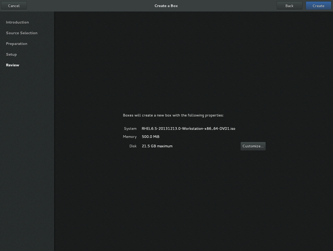
Figure 22.6. Review screen
These details can be left as is, in which case proceed to the final step, or:Optional: customize the details
clicking allows you to adjust the configuration of the guest virtual machine, such as the memory and disk size.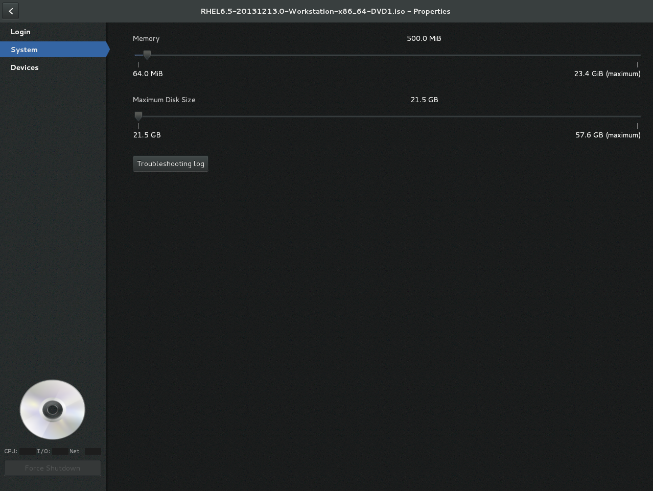
Figure 22.7. Customization screen
Create
Click . The new guest virtual machine will open.
Chapter 23. Manipulating the Domain XML
<domain> element required for all guest virtual machines. The domain XML has two attributes: type and id. type specifies the hypervisor used for running the domain. The allowed values are driver-specific, but include KVM and others. id is a unique integer identifier for the running guest virtual machine. Inactive machines have no id value. The sections in this chapter will describe the components of the domain XML. Additional chapters in this manual may see this chapter when manipulation of the domain XML is required.
Important
virsh and the Virtual Machine Manager) and commands (such as virt-xml) to edit the components of the domain XML file. Do not open and edit the domain XML file directly with a text editor. If you absolutely must edit the domain XML file directly, use the virsh edit command.
Note
23.1. General Information and Metadata
<domain type='kvm' id='3'>
<name>fv0</name>
<uuid>4dea22b31d52d8f32516782e98ab3fa0</uuid>
<title>A short description - title - of the domain</title>
<description>A human readable description</description>
<metadata>
<app1:foo xmlns:app1="http://app1.org/app1/">..</app1:foo>
<app2:bar xmlns:app2="http://app1.org/app2/">..</app2:bar>
</metadata>
...
</domain>
Figure 23.1. Domain XML metadata
Table 23.1. General metadata elements
| Element | Description |
|---|---|
<name> | Assigns a name for the virtual machine. This name should consist only of alpha-numeric characters and is required to be unique within the scope of a single host physical machine. It is often used to form the file name for storing the persistent configuration files. |
<uuid> | Assigns a globally unique identifier for the virtual machine. The format must be RFC 4122-compliant, for example 3e3fce45-4f53-4fa7-bb32-11f34168b82b. If omitted when defining or creating a new machine, a random UUID is generated. It is also possible to provide the UUID using a sysinfo specification. |
<title> | Creates space for a short description of the domain. The title should not contain any new lines. |
<description> | Different from the title, this data is not used by libvirt. It can contain any information the user chooses to display. |
<metadata> | Can be used by applications to store custom metadata in the form of XML nodes/trees. Applications must use custom name spaces on XML nodes/trees, with only one top-level element per name space (if the application needs structure, they should have sub-elements to their name space element). |
23.2. Operating System Booting
23.2.1. BIOS Boot Loader
<os> section of the domain XML contains the following information:
...
<os>
<type>hvm</type>
<boot dev='fd'/>
<boot dev='hd'/>
<boot dev='cdrom'/>
<boot dev='network'/>
<bootmenu enable='yes'/>
<smbios mode='sysinfo'/>
<bios useserial='yes' rebootTimeout='0'/>
</os>
...Figure 23.2. BIOS boot loader domain XML
Table 23.2. BIOS boot loader elements
| Element | Description |
|---|---|
<type> | Specifies the type of operating system to be booted on the guest virtual machine. hvm indicates that the operating system is designed to run on bare metal and requires full virtualization. linux refers to an operating system that supports the KVM hypervisor guest ABI. There are also two optional attributes: arch specifies the CPU architecture to virtualization, and machine refers to the machine type. For more information, see the libvirt upstream documentation. |
<boot> | Specifies the next boot device to consider with one of the following values:fd, hd, cdrom or network. The boot element can be repeated multiple times to set up a priority list of boot devices to try in turn. Multiple devices of the same type are sorted according to their targets while preserving the order of buses. After defining the domain, its XML configuration returned by libvirt lists devices in the sorted order. Once sorted, the first device is marked as bootable. For more information, see the libvirt upstream documentation. |
<bootmenu> | Determines whether or not to enable an interactive boot menu prompt on guest virtual machine start up. The enable attribute can be either yes or no. If not specified, the hypervisor default is used. |
<smbios> | determines how SMBIOS information is made visible in the guest virtual machine. The mode attribute must be specified, as either emulate (allows the hypervisor generate all values), host (copies all of Block 0 and Block 1, except for the UUID, from the host physical machine's SMBIOS values; the virConnectGetSysinfo call can be used to see what values are copied), or sysinfo (uses the values in the sysinfo element). If not specified, the hypervisor's default setting is used. |
<bios> | This element has attribute useserial with possible values yes or no. The attribute enables or disables the Serial Graphics Adapter, which enables users to see BIOS messages on a serial port. Therefore, one needs to have serial port defined. The rebootTimeout attribute controls whether and after how long the guest virtual machine should start booting again in case the boot fails (according to the BIOS). The value is set in milliseconds with a maximum of 65535; setting -1 disables the reboot. |
23.2.2. Direct Kernel Boot
initrd stored in the host physical machine operating system, allowing command-line arguments to be passed directly to the installer. This capability is usually available for both fully virtualized and paravirtualized guest virtual machines.
...
<os>
<type>hvm</type>
<kernel>/root/f8-i386-vmlinuz</kernel>
<initrd>/root/f8-i386-initrd</initrd>
<cmdline>console=ttyS0 ks=http://example.com/f8-i386/os/</cmdline>
<dtb>/root/ppc.dtb</dtb>
</os>
...
Figure 23.3. Direct kernel boot
Table 23.3. Direct kernel boot elements
| Element | Description |
|---|---|
<type> | Same as described in the BIOS boot section. |
<kernel> | Specifies the fully-qualified path to the kernel image in the host physical machine operating system. |
<initrd> | Specifies the fully-qualified path to the (optional) ramdisk image in the host physical machine operating system. |
<cmdline> | Specifies arguments to be passed to the kernel (or installer) at boot time. This is often used to specify an alternate primary console (such as a serial port), or the installation media source or kickstart file. |
23.2.3. Container Boot
init binary is required, using the init element. By default, this will be launched with no arguments. To specify the initial argv, use the initarg element, repeated as many times as required. The cmdline element provides an equivalent to /proc/cmdline but will not affect <initarg>.
... <os> <type arch='x86_64'>exe</type> <init>/bin/systemd</init> <initarg>--unit</initarg> <initarg>emergency.service</initarg> </os> ...
Figure 23.4. Container boot
23.3. SMBIOS System Information
dmidecode command in the guest virtual machine). The optional sysinfo element covers all such categories of information.
...
<os>
<smbios mode='sysinfo'/>
...
</os>
<sysinfo type='smbios'>
<bios>
<entry name='vendor'>LENOVO</entry>
</bios>
<system>
<entry name='manufacturer'>Fedora</entry>
<entry name='vendor'>Virt-Manager</entry>
</system>
</sysinfo>
...
Figure 23.5. SMBIOS system information
<sysinfo> element has a mandatory attribute type that determines the layout of sub-elements, and may be defined as follows:
<smbios>- Sub-elements call out specific SMBIOS values, which will affect the guest virtual machine if used in conjunction with thesmbiossub-element of the<os>element. Each sub-element of<sysinfo>names a SMBIOS block, and within those elements can be a list of entry elements that describe a field within the block. The following blocks and entries are recognized:<bios>- This is block 0 of SMBIOS, with entry names drawn fromvendor,version,date, andrelease.<system>- This is block 1 of SMBIOS, with entry names drawn frommanufacturer,product,version,serial,uuid,sku, andfamily. If auuidentry is provided alongside a top-leveluuidelement, the two values must match.
23.4. CPU allocation
<domain> ... <vcpu placement='static' cpuset="1-4,^3,6" current="1">2</vcpu> ... </domain>
Figure 23.6. CPU Allocation
<vcpu> element defines the maximum number of virtual CPUs allocated for the guest virtual machine operating system, which must be between 1 and the maximum number supported by the hypervisor. This element can contain an optional cpuset attribute, which is a comma-separated list of physical CPU numbers that the domain process and virtual CPUs can be pinned to by default.
cputune attribute. If the emulatorpin attribute is specified in <cputune>, cpuset specified by <vcpu> will be ignored.
vcpupin cause cpuset settings to be ignored. For virtual CPUs where vcpupin is not specified, it will be pinned to the physical CPUs specified by cpuset. Each element in the cpuset list is either a single CPU number, a range of CPU numbers, or a caret (^) followed by a CPU number to be excluded from a previous range. The attribute current can be used to specify whether fewer than the maximum number of virtual CPUs should be enabled.
placement optional attribute can be used to indicate the CPU placement mode for domain processes. The value of placement can be set as one of the following:
static- pins the vCPU to the physical CPUs defined by thecpusetattribute. Ifcpusetis not defined, the domain processes will be pinned to all the available physical CPUs.auto- indicates the domain process will be pinned to the advisory nodeset from the querying numad, and the value of attributecpusetwill be ignored if it is specified.
Note
cpuset attribute is used along with placement, the value of placement defaults to the value of the <numatune> element (if it is used), or to static.
23.5. CPU tuning
<domain>
...
<cputune>
<vcpupin vcpu="0" cpuset="1-4,^2"/>
<vcpupin vcpu="1" cpuset="0,1"/>
<vcpupin vcpu="2" cpuset="2,3"/>
<vcpupin vcpu="3" cpuset="0,4"/>
<emulatorpin cpuset="1-3"/>
<shares>2048</shares>
<period>1000000</period>
<quota>-1</quota>
<emulator_period>1000000</emulator_period>
<emulator_quota>-1</emulator_quota>
</cputune>
...
</domain>
Figure 23.7. CPU Tuning
Table 23.4. CPU tuning elements
| Element | Description |
|---|---|
<cputune> | Provides details regarding the CPU tunable parameters for the domain. This is optional. |
<vcpupin> | Specifies which of host physical machine's physical CPUs the domain vCPU will be pinned to. If this is omitted, and the cpuset attribute of the <vcpu> element is not specified, the vCPU is pinned to all the physical CPUs by default. It contains two required attributes: the <vcpu> attribute specifies id, and the cpuset attribute is same as the cpuset attribute in the <vcpu> element. |
<emulatorpin> | Specifies which of the host physical machine CPUs the "emulator" (a subset of a domains not including <vcpu>) will be pinned to. If this is omitted, and the cpuset attribute in the <vcpu> element is not specified, the "emulator" is pinned to all the physical CPUs by default. It contains one required cpuset attribute specifying which physical CPUs to pin to. emulatorpin is not allowed if the placement attribute in the <vcpu> element is set as auto. |
<shares> | Specifies the proportional weighted share for the domain. If this is omitted, it defaults to the operating system provided defaults. If there is no unit for the value, it is calculated relative to the setting of the other guest virtual machine. For example, a guest virtual machine configured with a <shares> value of 2048 will get twice as much CPU time as a guest virtual machine configured with a <shares> value of 1024. |
<period> | Specifies the enforcement interval in microseconds. By using <period>, each of the domain's vCPUs will not be allowed to consume more than its allotted quota worth of run time. This value should be within the following range: 1000-1000000. A <period> with a value of 0 means no value. |
<quota> | Specifies the maximum allowed bandwidth in microseconds. A domain with <quota> as any negative value indicates that the domain has infinite bandwidth, which means that it is not bandwidth controlled. The value should be within the following range: 1000 - 18446744073709551 or less than 0. A quota with value of 0 means no value. You can use this feature to ensure that all vCPUs run at the same speed. |
<emulator_period> | Specifies the enforcement interval in microseconds. Within an <emulator_period>, emulator threads (those excluding vCPUs) of the domain will not be allowed to consume more than the <emulator_quota> worth of run time. The <emulator_period> value should be in the following range: 1000 - 1000000. An <emulator_period> with value of 0 means no value. |
<emulator_quota> | Specifies the maximum allowed bandwidth in microseconds for the domain's emulator threads (those excluding vCPUs). A domain with an <emulator_quota> as a negative value indicates that the domain has infinite bandwidth for emulator threads (those excluding vCPUs), which means that it is not bandwidth controlled. The value should be in the following range: 1000 - 18446744073709551, or less than 0. An <emulator_quota> with value 0 means no value. |
23.6. Memory Backing
<domain>
...
<memoryBacking>
<hugepages>
<page size="1" unit="G" nodeset="0-3,5"/>
<page size="2" unit="M" nodeset="4"/>
</hugepages>
<nosharepages/>
<locked/>
</memoryBacking>
...
</domain>
Figure 23.8. Memory backing
23.7. Memory Tuning
<domain>
...
<memtune>
<hard_limit unit='G'>1</hard_limit>
<soft_limit unit='M'>128</soft_limit>
<swap_hard_limit unit='G'>2</swap_hard_limit>
<min_guarantee unit='bytes'>67108864</min_guarantee>
</memtune>
...
</domain>
Figure 23.9. Memory tuning
<memtune> is optional, the components of this section of the domain XML are as follows:
Table 23.5. Memory tuning elements
| Element | Description |
|---|---|
<memtune> | Provides details regarding the memory tunable parameters for the domain. If this is omitted, it defaults to the operating system provided defaults. As parameters are applied to the process as a whole, when setting limits, determine values by adding the guest virtual machine RAM to the guest virtual machine video RAM, allowing for some memory overhead. For each tunable, it is possible to designate which unit the number is in on input, using the same values as for <memory>. For backwards compatibility, output is always in kibibytes (KiB). |
<hard_limit> | The maximum memory the guest virtual machine can use. This value is expressed in kibibytes (blocks of 1024 bytes). |
<soft_limit> | The memory limit to enforce during memory contention. This value is expressed in kibibytes (blocks of 1024 bytes). |
<swap_hard_limit> | The maximum memory plus swap the guest virtual machine can use. This value is expressed in kibibytes (blocks of 1024 bytes). This must be more than <hard_limit> value. |
<min_guarantee> | The guaranteed minimum memory allocation for the guest virtual machine. This value is expressed in kibibytes (blocks of 1024 bytes). |
23.8. Memory Allocation
dumpCore can be used to control whether the guest virtual machine's memory should be included in the generated core dump(dumpCore='on') or not included (dumpCore='off'). Note that the default setting is on, so unless the parameter is set to off, the guest virtual machine memory will be included in the core dumpfile.
<maxMemory> element determines maximum run-time memory allocation of the guest. The slots attribute specifies the number of slots available for adding memory to the guest.
<memory> element specifies the maximum allocation of memory for the guest at boot time. This can also be set using the NUMA cell size configuration, and can be increased by hot-plugging of memory to the limit specified by maxMemory.
<currentMemory> element determines the actual memory allocation for a guest virtual machine. This value can be less than the maximum allocation (set by <memory>) to allow for the guest virtual machine memory to balloon as needed. If omitted, this defaults to the same value as the <memory> element. The unit attribute behaves the same as for memory.
<domain> <maxMemory slots='16' unit='KiB'>1524288</maxMemory> <memory unit='KiB' dumpCore='off'>524288</memory> <!-- changes the memory unit to KiB and does not allow the guest virtual machine's memory to be included in the generated core dumpfile --> <currentMemory unit='KiB'>524288</currentMemory> <!-- makes the current memory unit 524288 KiB --> ... </domain>
Figure 23.10. Memory unit
23.9. NUMA Node Tuning
virsh edit, the following domain XML parameters are affected:
<domain>
...
<numatune>
<memory mode="strict" nodeset="1-4,^3"/>
</numatune>
...
</domain>
Figure 23.11. NUMA node tuning
Table 23.6. NUMA node tuning elements
| Element | Description |
|---|---|
<numatune> | Provides details of how to tune the performance of a NUMA host physical machine by controlling NUMA policy for domain processes. |
<memory> | Specifies how to allocate memory for the domain processes on a NUMA host physical machine. It contains several optional attributes. The mode attribute can be set to interleave, strict, or preferred. If no value is given it defaults to strict. The nodeset attribute specifies the NUMA nodes, using the same syntax as the cpuset attribute of the <vcpu> element. Attribute placement can be used to indicate the memory placement mode for the domain process. Its value can be either static or auto. If the <nodeset> attribute is specified it defaults to the <placement> of <vcpu>, or static. auto indicates the domain process will only allocate memory from the advisory nodeset returned from querying numad and the value of the nodeset attribute will be ignored if it is specified. If the <placement> attribute in vcpu is set to auto, and the <numatune> attribute is not specified, a default <numatune> with <placement> auto and strict mode will be added implicitly. |
23.10. Block I/O Tuning
<domain>
...
<blkiotune>
<weight>800</weight>
<device>
<path>/dev/sda</path>
<weight>1000</weight>
</device>
<device>
<path>/dev/sdb</path>
<weight>500</weight>
</device>
</blkiotune>
...
</domain>
Figure 23.12. Block I/O tuning
Table 23.7. Block I/O tuning elements
| Element | Description |
|---|---|
<blkiotune> | This optional element provides the ability to tune blkio cgroup tunable parameters for the domain. If this is omitted, it defaults to the operating system provided defaults. |
<weight> | This optional weight element is the overall I/O weight of the guest virtual machine. The value should be within the range 100 - 1000. |
<device> | The domain may have multiple <device> elements that further tune the weights for each host physical machine block device in use by the domain. Note that multiple guest virtual machine disks can share a single host physical machine block device. In addition, as they are backed by files within the same host physical machine file system, this tuning parameter is at the global domain level, rather than being associated with each guest virtual machine disk device (contrast this to the <iotune> element which can be applied to a single <disk>). Each device element has two mandatory sub-elements, <path> describing the absolute path of the device, and <weight> giving the relative weight of that device, which has an acceptable range of 100 - 1000. |
23.11. Resource Partitioning
<resource> element groups together configurations related to resource partitioning. It currently supports a child element partition whose content defines the path of the resource partition in which to place the domain. If no partition is listed, then the domain will be placed in a default partition. The partition must be created prior to starting the guest virtual machine. Only the (hypervisor-specific) default partition can be assumed to exist by default.
<resource> <partition>/virtualmachines/production</partition> </resource>
Figure 23.13. Resource partitioning
23.12. CPU Models and Topology
qemu32 and qemu64 are basic CPU models, but there are other models (with additional features) available. Each model and its topology is specified using the following elements from the domain XML:
<cpu match='exact'>
<model fallback='allow'>core2duo</model>
<vendor>Intel</vendor>
<topology sockets='1' cores='2' threads='1'/>
<feature policy='disable' name='lahf_lm'/>
</cpu>Figure 23.14. CPU model and topology example 1
<cpu mode='host-model'> <model fallback='forbid'/> <topology sockets='1' cores='2' threads='1'/> </cpu>
Figure 23.15. CPU model and topology example 2
<cpu mode='host-passthrough'/>
Figure 23.16. CPU model and topology example 3
<cpu> element such as the following may be used:
<cpu> <topology sockets='1' cores='2' threads='1'/> </cpu>
Figure 23.17. CPU model and topology example 4
<cpu mode='custom'> <model>POWER8</model> </cpu>
Figure 23.18. PPC64/PSeries CPU model example
<cpu mode='host-passthrough'/>
Figure 23.19. aarch64/virt CPU model example
Table 23.8. CPU model and topology elements
| Element | Description |
|---|---|
<cpu> | This is the main container for describing guest virtual machine CPU requirements. |
<match> | Specifies how the virtual CPU is provided to the guest virtual machine must match these requirements. The match attribute can be omitted if topology is the only element within <cpu>. Possible values for the match attribute are:
match attribute can be omitted and will default to exact. |
<mode> | This optional attribute may be used to make it easier to configure a guest virtual machine CPU to be as close to the host physical machine CPU as possible. Possible values for the mode attribute are:
|
<model> | Specifies the CPU model requested by the guest virtual machine. The list of available CPU models and their definition can be found in the cpu_map.xml file installed in libvirt's data directory. If a hypervisor is unable to use the exact CPU model, libvirt automatically falls back to a closest model supported by the hypervisor while maintaining the list of CPU features. An optional fallback attribute can be used to forbid this behavior, in which case an attempt to start a domain requesting an unsupported CPU model will fail. Supported values for fallback attribute are: allow (the default), and forbid. The optional vendor_id attribute can be used to set the vendor ID seen by the guest virtual machine. It must be exactly 12 characters long. If not set, the vendor iID of the host physical machine is used. Typical possible values are AuthenticAMD and GenuineIntel. |
<vendor> | Specifies the CPU vendor requested by the guest virtual machine. If this element is missing, the guest virtual machine runs on a CPU matching given features regardless of its vendor. The list of supported vendors can be found in cpu_map.xml. |
<topology> | Specifies the requested topology of the virtual CPU provided to the guest virtual machine. Three non-zero values must be given for sockets, cores, and threads: the total number of CPU sockets, number of cores per socket, and number of threads per core, respectively. |
<feature> | Can contain zero or more elements used to fine-tune features provided by the selected CPU model. The list of known feature names can be found in the cpu_map.xml file. The meaning of each feature element depends on its policy attribute, which has to be set to one of the following values:
|
23.12.1. Changing the Feature Set for a Specified CPU
Procedure 23.1. Enabling and disabling CPU features
- To begin, shut down the guest virtual machine.
- Open the guest virtual machine's configuration file by running the
virsh edit [domain]command. - Change the parameters within the
<feature>or<model>to include the attribute value'allow'to force the feature to be allowed, or'forbid'to deny support for the feature.<!-- original feature set --> <cpu mode='host-model'> <model fallback='allow'/> <topology sockets='1' cores='2' threads='1'/> </cpu> <!--changed feature set--> <cpu mode='host-model'> <model fallback='forbid'/> <topology sockets='1' cores='2' threads='1'/> </cpu>
Figure 23.20. Example for enabling or disabling CPU features
<!--original feature set--> <cpu match='exact'> <model fallback='allow'>core2duo</model> <vendor>Intel</vendor> <topology sockets='1' cores='2' threads='1'/> <feature policy='disable' name='lahf_lm'/> </cpu> <!--changed feature set--> <cpu match='exact'> <model fallback='allow'>core2duo</model> <vendor>Intel</vendor> <topology sockets='1' cores='2' threads='1'/> <feature policy='enable' name='lahf_lm'/> </cpu>Figure 23.21. Example 2 for enabling or disabling CPU features
- When you have completed the changes, save the configuration file and start the guest virtual machine.
23.12.2. Guest Virtual Machine NUMA Topology
<numa> element in the domain XML:
<cpu>
<numa>
<cell cpus='0-3' memory='512000'/>
<cell cpus='4-7' memory='512000'/>
</numa>
</cpu>
...
Figure 23.22. Guest virtual machine NUMA topology
cpus specifies the CPU or range of CPUs that are part of the node. memory specifies the node memory in kibibytes (blocks of 1024 bytes). Each cell or node is assigned a cellid or nodeid in increasing order starting from 0.
23.13. Events Configuration
<on_poweroff>destroy</on_poweroff> <on_reboot>restart</on_reboot> <on_crash>restart</on_crash> <on_lockfailure>poweroff</on_lockfailure>
Figure 23.23. Events Configuration
Table 23.9. Event configuration elements
| State | Description |
|---|---|
<on_poweroff> | Specifies the action that is to be executed when the guest virtual machine requests a power off. Four arguments are possible:
|
<on_reboot> | Specifies the action to be executed when the guest virtual machine requests a reboot. Four arguments are possible:
|
<on_crash> | Specifies the action that is to be executed when the guest virtual machine crashes. In addition, it supports these additional actions:
|
<on_lockfailure> | Specifies the action to take when a lock manager loses resource locks. The following actions are recognized by libvirt, although not all of them need to be supported by individual lock managers. When no action is specified, each lock manager will take its default action. The following arguments are possible:
|
23.14. Hypervisor Features
state='on') or disabled (state='off').
...
<features>
<pae/>
<acpi/>
<apic/>
<hap/>
<privnet/>
<hyperv>
<relaxed state='on'/>
</hyperv>
</features>
...
Figure 23.24. Hypervisor features
<features> element, if a <state> is not specified it is disabled. The available features can be found by calling the capabilities XML, but a common set for fully virtualized domains are:
Table 23.10. Hypervisor features elements
| State | Description |
|---|---|
<pae> | Physical address extension mode allows 32-bit guest virtual machines to address more than 4 GB of memory. |
<acpi> | Useful for power management. For example, with KVM guest virtual machines it is required for graceful shutdown to work. |
<apic> | Allows the use of programmable IRQ management. This element has an optional attribute eoi with values on and off, which sets the availability of EOI (End of Interrupt) for the guest virtual machine. |
<hap> | Enables the use of hardware assisted paging if it is available in the hardware. |
23.15. Timekeeping
<clock> and <timer> elements in the domain XML. The domain XML can be edited using the virsh edit command. For details, see Section 20.22, “Editing a Guest Virtual Machine's XML Configuration Settings”.
...
<clock offset='localtime'>
<timer name='rtc' tickpolicy='catchup' track='guest'>
<catchup threshold='123' slew='120' limit='10000'/>
</timer>
<timer name='pit' tickpolicy='delay'/>
</clock>
...
Figure 23.25. Timekeeping
Table 23.11. Timekeeping elements
| State | Description |
|---|---|
<clock> | The <clock> element is used to determine how the guest virtual machine clock is synchronized with the host physical machine clock. The offset attribute takes four possible values, allowing for fine grained control over how the guest virtual machine clock is synchronized to the host physical machine. Note that hypervisors are not required to support all policies across all time sources
|
<timer> | See Note |
<present> | Specifies whether a particular timer is available to the guest virtual machine. Can be set to yes or no. |
Note
<clock> element can have zero or more <timer> elements as children. The <timer> element specifies a time source used for guest virtual machine clock synchronization.
<timer> element only the name is required, and all other attributes are optional:
name- Selects whichtimeris being modified. The following values are acceptable:kvmclock,pit, orrtc.track- Specifies the timer track. The following values are acceptable:boot,guest, orwall.trackis only valid forname="rtc".tickpolicy- Determines what happens when the deadline for injecting a tick to the guest virtual machine is missed. The following values can be assigned:delay- Continues to deliver ticks at the normal rate. The guest virtual machine time will be delayed due to the late tick.catchup- Delivers ticks at a higher rate in order to catch up with the missed tick. The guest virtual machine time is not displayed once catch up is complete. In addition, there can be three optional attributes, each a positive integer: threshold, slew, and limit.merge- Merges the missed tick(s) into one tick and injects them. The guest virtual machine time may be delayed, depending on how the merge is done.discard- Throws away the missed tick(s) and continues with future injection at its default interval setting. The guest virtual machine time may be delayed, unless there is an explicit statement for handling lost ticks.
Note
Example 23.1. Always synchronize to UTC
<clock offset="utc" />
Example 23.2. Always synchronize to the host physical machine timezone
<clock offset="localtime" />
Example 23.3. Synchronize to an arbitrary time zone
<clock offset="timezone" timezone="Europe/Paris" />
Example 23.4. Synchronize to UTC + arbitrary offset
<clock offset="variable" adjustment="123456" />
23.16. Timer Element Attributes
name element contains the name of the time source to be used. It can have any of the following values:
Table 23.12. Name attribute values
| Value | Description |
|---|---|
| pit | Programmable Interval Timer - a timer with periodic interrupts. When using this attribute, the tickpolicy delay becomes the default setting. |
| rtc | Real Time Clock - a continuously running timer with periodic interrupts. This attribute supports the tickpolicy catchup sub-element. |
| kvmclock | KVM clock - the recommended clock source for KVM guest virtual machines. KVM pvclock, or kvm-clock allows guest virtual machines to read the host physical machine’s wall clock time. |
track attribute specifies what is tracked by the timer, and is only valid for a name value of rtc.
Table 23.13. track attribute values
| Value | Description |
|---|---|
| boot | Corresponds to old host physical machine option, this is an unsupported tracking option. |
| guest | RTC always tracks the guest virtual machine time. |
| wall | RTC always tracks the host time. |
tickpolicy attribute and the values dictate the policy that is used to pass ticks on to the guest virtual machine.
Table 23.14. tickpolicy attribute values
| Value | Description |
|---|---|
| delay | Continue to deliver at normal rate (ticks are delayed). |
| catchup | Deliver at a higher rate to catch up. |
| merge | Ticks merged into one single tick. |
| discard | All missed ticks are discarded. |
present attribute is used to override the default set of timers visible to the guest virtual machine. The present attribute can take the following values:
Table 23.15. present attribute values
| Value | Description |
|---|---|
| yes | Force this timer to be visible to the guest virtual machine. |
| no | Force this timer to not be visible to the guest virtual machine. |
23.17. Devices
<devices> element.
- virtio-scsi-pci - PCI bus storage device
- virtio-blk-pci - PCI bus storage device
- virtio-net-pci - PCI bus network device also known as virtio-net
- virtio-serial-pci - PCI bus input device
- virtio-balloon-pci - PCI bus memory balloon device
- virtio-rng-pci - PCI bus virtual random number generator device
Important
virtio-balloon-pci and virtio-rng-pci will accept a vector argument.
...
<devices>
<emulator>/usr/libexec/qemu-kvm</emulator>
</devices>
...
Figure 23.26. Devices - child elements
<emulator> element specify the fully qualified path to the device model emulator binary. The capabilities XML specifies the recommended default emulator to use for each particular domain type or architecture combination.
23.17.1. Hard Drives, Floppy Disks, and CD-ROMs
<disk> element.
<disk type='network'>
<driver name="qemu" type="raw" io="threads" ioeventfd="on" event_idx="off"/>
<source protocol="sheepdog" name="image_name">
<host name="hostname" port="7000"/>
</source>
<target dev="hdb" bus="ide"/>
<boot order='1'/>
<transient/>
<address type='drive' controller='0' bus='1' unit='0'/>
</disk>Figure 23.27. Devices - Hard drives, floppy disks, CD-ROMs Example
<disk type='network'>
<driver name="qemu" type="raw"/>
<source protocol="rbd" name="image_name2">
<host name="hostname" port="7000"/>
</source>
<target dev="hdd" bus="ide"/>
<auth username='myuser'>
<secret type='ceph' usage='mypassid'/>
</auth>
</disk>Figure 23.28. Devices - Hard drives, floppy disks, CD-ROMs Example 2
<disk type='block' device='cdrom'>
<driver name='qemu' type='raw'/>
<target dev='hdc' bus='ide' tray='open'/>
<readonly/>
</disk>
<disk type='network' device='cdrom'>
<driver name='qemu' type='raw'/>
<source protocol="http" name="url_path">
<host name="hostname" port="80"/>
</source>
<target dev='hdc' bus='ide' tray='open'/>
<readonly/>
</disk>Figure 23.29. Devices - Hard drives, floppy disks, CD-ROMs Example 3
<disk type='network' device='cdrom'>
<driver name='qemu' type='raw'/>
<source protocol="https" name="url_path">
<host name="hostname" port="443"/>
</source>
<target dev='hdc' bus='ide' tray='open'/>
<readonly/>
</disk>
<disk type='network' device='cdrom'>
<driver name='qemu' type='raw'/>
<source protocol="ftp" name="url_path">
<host name="hostname" port="21"/>
</source>
<target dev='hdc' bus='ide' tray='open'/>
<readonly/>
</disk>Figure 23.30. Devices - Hard drives, floppy disks, CD-ROMs Example 4
<disk type='network' device='cdrom'>
<driver name='qemu' type='raw'/>
<source protocol="ftps" name="url_path">
<host name="hostname" port="990"/>
</source>
<target dev='hdc' bus='ide' tray='open'/>
<readonly/>
</disk>
<disk type='network' device='cdrom'>
<driver name='qemu' type='raw'/>
<source protocol="tftp" name="url_path">
<host name="hostname" port="69"/>
</source>
<target dev='hdc' bus='ide' tray='open'/>
<readonly/>
</disk>
<disk type='block' device='lun'>
<driver name='qemu' type='raw'/>
<source dev='/dev/sda'/>
<target dev='sda' bus='scsi'/>
<address type='drive' controller='0' bus='0' target='3' unit='0'/>
</disk>Figure 23.31. Devices - Hard drives, floppy disks, CD-ROMs Example 5
<disk type='block' device='disk'>
<driver name='qemu' type='raw'/>
<source dev='/dev/sda'/>
<geometry cyls='16383' heads='16' secs='63' trans='lba'/>
<blockio logical_block_size='512' physical_block_size='4096'/>
<target dev='hda' bus='ide'/>
</disk>
<disk type='volume' device='disk'>
<driver name='qemu' type='raw'/>
<source pool='blk-pool0' volume='blk-pool0-vol0'/>
<target dev='hda' bus='ide'/>
</disk>
<disk type='network' device='disk'>
<driver name='qemu' type='raw'/>
<source protocol='iscsi' name='iqn.2013-07.com.example:iscsi-nopool/2'>
<host name='example.com' port='3260'/>
</source>
<auth username='myuser'>
<secret type='chap' usage='libvirtiscsi'/>
</auth>
<target dev='vda' bus='virtio'/>
</disk>Figure 23.32. Devices - Hard drives, floppy disks, CD-ROMs Example 6
<disk type='network' device='lun'>
<driver name='qemu' type='raw'/>
<source protocol='iscsi' name='iqn.2013-07.com.example:iscsi-nopool/1'>
iqn.2013-07.com.example:iscsi-pool
<host name='example.com' port='3260'/>
</source>
<auth username='myuser'>
<secret type='chap' usage='libvirtiscsi'/>
</auth>
<target dev='sda' bus='scsi'/>
</disk>
<disk type='volume' device='disk'>
<driver name='qemu' type='raw'/>
<source pool='iscsi-pool' volume='unit:0:0:1' mode='host'/>
<auth username='myuser'>
<secret type='chap' usage='libvirtiscsi'/>
</auth>
<target dev='vda' bus='virtio'/>
</disk>Figure 23.33. Devices - Hard drives, floppy disks, CD-ROMs Example 7
<disk type='volume' device='disk'>
<driver name='qemu' type='raw'/>
<source pool='iscsi-pool' volume='unit:0:0:2' mode='direct'/>
<auth username='myuser'>
<secret type='chap' usage='libvirtiscsi'/>
</auth>
<target dev='vda' bus='virtio'/>
</disk>
<disk type='file' device='disk'>
<driver name='qemu' type='raw' cache='none'/>
<source file='/tmp/test.img' startupPolicy='optional'/>
<target dev='sdb' bus='scsi'/>
<readonly/>
</disk>
<disk type='file' device='disk'>
<driver name='qemu' type='raw' discard='unmap'/>
<source file='/var/lib/libvirt/images/discard1.img'/>
<target dev='vdb' bus='virtio'/>
<alias name='virtio-disk1'/>
<address type='pci' domain='0x0000' bus='0x00' slot='0x09' function='0x0'/>
</disk>
</devices>
...
Figure 23.34. Devices - Hard drives, floppy disks, CD-ROMs Example 8
23.17.1.1. Disk element
<disk> element is the main container for describing disks. The attribute type can be used with the <disk> element. The following types are allowed:
fileblockdirnetwork
23.17.1.2. Source element
<file>- Thefileattribute specifies the fully-qualified path to the file in which the disk is located.<block>- Thedevattribute specifies the fully-qualified path to the host device that serves as the disk.<dir>- Thedirattribute specifies the fully-qualified path to the directory used as the disk.<network>- Theprotocolattribute specifies the protocol used to access the requested image. Possible values are:nbd,isci,rbd,sheepdog, andgluster.- If the
protocolattribute isrbd,sheepdog, orgluster, an additional attribute,nameis mandatory. This attribute specifies which volume and image will be used. - If the
protocolattribute isnbd, thenameattribute is optional. - If the
protocolattribute isisci, thenameattribute may include a logical unit number, separated from the target's name with a slash. For example: iqn.2013-07.com.example:iscsi-pool/1. If not specified, the default LUN is zero.
<volume>- The underlying disk source is represented by thepoolandvolumeattributes.<pool>- The name of the storage pool (managed bylibvirt) where the disk source resides.<volume>- The name of the storage volume (managed bylibvirt) used as the disk source.The value for thevolumeattribute is the output from the Name column of avirsh vol-list [pool-name]
network, the source may have zero or more host sub-elements used to specify the host physical machines to connect, including: type='dir' and type='network'. For a file disk type which represents a CD-ROM or floppy (the device attribute), it is possible to define the policy for what to do with the disk if the source file is not accessible. This is done by setting the startupPolicy attribute with one of the following values:
mandatorycauses a failure if missing for any reason. This is the default setting.requisitecauses a failure if missing on boot up, drops if missing on migrate, restore, or revert.optionaldrops if missing at any start attempt.
23.17.1.3. Mirror element
BlockCopy operation, where the <mirror> location in the attribute file will eventually have the same contents as the source, and with the file format in attribute format (which might differ from the format of the source). If an attribute ready is present, then it is known the disk is ready to pivot; otherwise, the disk is probably still copying. For now, this element only valid in output; it is ignored on input.
23.17.1.4. Target element
<target> element controls the bus or device under which the disk is exposed to the guest virtual machine operating system. The dev attribute indicates the logical device name. The actual device name specified is not guaranteed to map to the device name in the guest virtual machine operating system. The optional bus attribute specifies the type of disk device to emulate; possible values are driver-specific, with typical values being ide, scsi, virtio, kvm, usb or sata. If omitted, the bus type is inferred from the style of the device name. For example, a device named 'sda' will typically be exported using a SCSI bus. The optional attribute tray indicates the tray status of the removable disks (for example, CD-ROM or Floppy disk), where the value can be either open or closed. The default setting is closed.
23.17.1.5. iotune element
<iotune> element provides the ability to provide additional per-device I/O tuning, with values that can vary for each device (contrast this to the blkiotune element, which applies globally to the domain). This element has the following optional sub-elements (note that any sub-element not specified or at all or specified with a value of 0 implies no limit):
<total_bytes_sec>- The total throughput limit in bytes per second. This element cannot be used with<read_bytes_sec>or<write_bytes_sec>.<read_bytes_sec>- The read throughput limit in bytes per second.<write_bytes_sec>- The write throughput limit in bytes per second.<total_iops_sec>- The total I/O operations per second. This element cannot be used with<read_iops_sec>or<write_iops_sec>.<read_iops_sec>- The read I/O operations per second.<write_iops_sec>- The write I/O operations per second.
23.17.1.6. Driver element
<driver> element allows specifying further details related to the hypervisor driver that is used to provide the disk. The following options may be used:
- If the hypervisor supports multiple back-end drivers, the
nameattribute selects the primary back-end driver name, while the optional type attribute provides the sub-type. - The optional
cacheattribute controls the cache mechanism. Possible values are:default,none,writethrough,writeback,directsync(similar towritethrough, but it bypasses the host physical machine page cache) andunsafe(host physical machine may cache all disk I/O, and sync requests from guest virtual machines are ignored). - The optional
error_policyattribute controls how the hypervisor behaves on a disk read or write error. Possible values arestop,report,ignore, andenospace. The default setting oferror_policyisreport. There is also an optionalrerror_policythat controls behavior for read errors only. If norerror_policyis given,error_policyis used for both read and write errors. Ifrerror_policyis given, it overrides theerror_policyfor read errors. Also note thatenospaceis not a valid policy for read errors, so iferror_policyis set toenospaceand norerror_policyis given, the read error default setting,reportwill be used. - The optional
ioattribute controls specific policies on I/O;kvmguest virtual machines supportthreadsandnative. The optionalioeventfdattribute allows users to set domain I/O asynchronous handling for virtio disk devices. The default is determined by the hypervisor. Accepted values areonandoff. Enabling this allows the guest virtual machine to be executed while a separate thread handles I/O. Typically, guest virtual machines experiencing high system CPU utilization during I/O will benefit from this. On the other hand, an overloaded host physical machine can increase guest virtual machine I/O latency. However, it is recommended that you do not change the default setting, and allow the hypervisor to determine the setting.Note
Theioeventfdattribute is included in the<driver>element of thediskXML section and also the<driver>element of thedeviceXML section. In the former case, it influences the virtIO disk, and in the latter case the SCSI disk. - The optional
event_idxattribute controls some aspects of device event processing and can be set to eitheronoroff. If set toon, it will reduce the number of interrupts and exits for the guest virtual machine. The default is determined by the hypervisor and the default setting ison. When this behavior is not required, settingoffforces the feature off. However, it is highly recommended that you not change the default setting, and allow the hypervisor to dictate the setting. - The optional
copy_on_readattribute controls whether to copy the read backing file into the image file. The accepted values can be eitheronor<off>.copy-on-readavoids accessing the same backing file sectors repeatedly, and is useful when the backing file is over a slow network. By defaultcopy-on-readisoff. - The
discard='unmap'can be set to enable discard support. The same line can be replaced withdiscard='ignore'to disable.discard='ignore'is the default setting.
23.17.1.7. Additional Device Elements
device element:
<boot>- Specifies that the disk is bootable.Additional boot values
<order>- Determines the order in which devices will be tried during boot sequence.<per-device>Boot elements cannot be used together with general boot elements in the BIOS boot loader section.
<encryption>- Specifies how the volume is encrypted.<readonly>- Indicates the device cannot be modified by the guest virtual machine virtual machine. This setting is the default for disks withattribute<device='cdrom'>.<shareable>Indicates the device is expected to be shared between domains (as long as hypervisor and operating system support this). Ifshareableis used,cache='no'should be used for that device.<transient>- Indicates that changes to the device contents should be reverted automatically when the guest virtual machine exits. With some hypervisors, marking a disktransientprevents the domain from participating in migration or snapshots.<serial>- Specifies the serial number of guest virtual machine's hard drive. For example,<serial>WD-WMAP9A966149</serial>.<wwn>- Specifies the World Wide Name (WWN) of a virtual hard disk or CD-ROM drive. It must be composed of 16 hexadecimal digits.<vendor>- Specifies the vendor of a virtual hard disk or CD-ROM device. It must not be longer than 8 printable characters.<product>- Specifies the product of a virtual hard disk or CD-ROM device. It must not be longer than 16 printable characters<host>- Supports the following attributes:The meaning of this element and the number of the elements depend on thename- specifies the host nameport- specifies the port numbertransport- specifies the transport typesocket- specifies the path to the socket
protocolattribute as shown in Additional host attributes based on the protocolAdditional host attributes based on the protocol
nbd- Specifies a server runningnbd-serverand may only be used for only one host physical machine. The default port for this protcol is 10809.rbd- Monitors servers of RBD type and may be used for one or more host physical machines.sheepdog- Specifies one of thesheepdogservers (default is localhost:7000) and can be used with one or none of the host physical machines.gluster- Specifies a server running a glusterd daemon and may be used for only only one host physical machine. The valid values for transport attribute aretcp,rdmaorunix. If nothing is specified,tcpis assumed. If transport isunix, thesocketattribute specifies path tounixsocket.
<address>- Ties the disk to a given slot of a controller. The actual<controller>device can often be inferred but it can also be explicitly specified. Thetypeattribute is mandatory, and is typicallypciordrive. For apcicontroller, additional attributes forbus,slot, andfunctionmust be present, as well as optionaldomainandmultifunction.multifunctiondefaults tooff. For adrivecontroller, additional attributescontroller,bus,target, andunitare available, each with a default setting of0.auth- Provides the authentication credentials needed to access the source. It includes a mandatory attributeusername, which identifies the user name to use during authentication, as well as a sub-elementsecretwith mandatory attributetype.geometry- Provides the ability to override geometry settings. This mostly useful for S390 DASD-disks or older DOS-disks. It can have the following parameters:cyls- Specifies the number of cylinders.heads- Specifies the number of heads.secs- Specifies the number of sectors per track.trans- Specifies the BIOS-Translation-Modes and can have the following values:none,lbaorauto.
blockio- Allows the block device to be overridden with any of the block device properties listed below:blockio options
logical_block_size- Reports to the guest virtual machine operating system and describes the smallest units for disk I/O.physical_block_size- Reports to the guest virtual machine operating system and describes the disk's hardware sector size, which can be relevant for the alignment of disk data.
23.17.2. Device Addresses
<address> sub-element to describe where the device placed on the virtual bus is presented to the guest virtual machine. If an address (or any optional attribute within an address) is omitted on input, libvirt will generate an appropriate address; but an explicit address is required if more control over layout is required. See below for device examples including an address element.
type that describes which bus the device is on. The choice of which address to use for a given device is constrained in part by the device and the architecture of the guest virtual machine. For example, a disk device uses type='disk', while a console device would use type='pci' on the 32-bit AMD and Intel, or AMD64 and Intel 64, guest virtual machines, or type='spapr-vio' on PowerPC64 pseries guest virtual machines. Each address <type> has additional optional attributes that control where on the bus the device will be placed. The additional attributes are as follows:
type='pci'- PCI addresses have the following additional attributes:domain(a 2-byte hex integer, not currently used by KVM)bus(a hex value between 0 and 0xff, inclusive)slot(a hex value between 0x0 and 0x1f, inclusive)function(a value between 0 and 7, inclusive)- Also available is the
multi-functionattribute, which controls turning on the multi-function bit for a particular slot or function in the PCI control register. This multi-function attribute defaults to'off', but should be set to'on'for function 0 of a slot that will have multiple functions used.
type='drive'-driveaddresses have the following additional attributes:controller- (a 2-digit controller number)bus- (a 2-digit bus number)target- (a 2-digit bus number)unit- (a 2-digit unit number on the bus)
type='virtio-serial'- Eachvirtio-serialaddress has the following additional attributes:controller- (a 2-digit controller number)bus- (a 2-digit bus number)slot- (a 2-digit slot within the bus)
type='ccid'- A CCID address, used for smart-cards, has the following additional attributes:bus- (a 2-digit bus number)slot- (a 2-digit slot within the bus)
type='usb'- USB addresses have the following additional attributes:bus- (a hex value between 0 and 0xfff, inclusive)port- (a dotted notation of up to four octets, such as 1.2 or 2.1.3.1)
type='spapr-vio'- On PowerPC pseries guest virtual machines, devices can be assigned to the SPAPR-VIO bus. It has a flat 64-bit address space; by convention, devices are generally assigned at a non-zero multiple of 0x1000, but other addresses are valid and permitted bylibvirt. The additionalregattribute, which determines the hex value address of the starting register, can be assigned to this attribute.
23.17.3. Controllers
<controller> element in the guest virtual machine XML:
...
<devices>
<controller type='ide' index='0'/>
<controller type='virtio-serial' index='0' ports='16' vectors='4'/>
<controller type='virtio-serial' index='1'>
<address type='pci' domain='0x0000' bus='0x00' slot='0x0a' function='0x0'/>
<controller type='scsi' index='0' model='virtio-scsi' num_queues='8'/>
</controller>
...
</devices>
...
Figure 23.35. Controller Elements
type, which must be one of "ide", "fdc", "scsi", "sata", "usb", "ccid", or "virtio-serial", and a mandatory attribute index which is the decimal integer describing in which order the bus controller is encountered (for use in controller attributes of address elements). The "virtio-serial" controller has two additional optional attributes, ports and vectors, which control how many devices can be connected through the controller.
<controller type='scsi'> has an optional attribute model, which is one of "auto", "buslogic", "ibmvscsi", "lsilogic", "lsias1068", "virtio-scsi or "vmpvscsi". The <controller type='scsi'> also has an attribute num_queues which enables multi-queue support for the number of queues specified. In addition, a ioeventfd attribute can be used, which specifies whether the controller should use asynchronous handling on the SCSI disk. Accepted values are "on" and "off".
"usb" controller has an optional attribute model, which is one of "piix3-uhci", "piix4-uhci", "ehci", "ich9-ehci1", "ich9-uhci1", "ich9-uhci2", "ich9-uhci3", "vt82c686b-uhci", "pci-ohci" or "nec-xhci". Additionally, if the USB bus needs to be explicitly disabled for the guest virtual machine, model='none' may be used. The PowerPC64 "spapr-vio" addresses do not have an associated controller.
address can specify the exact relationship of the controller to its master bus, with semantics given above.
master to specify the exact relationship of the companion to its master controller. A companion controller is on the same bus as its master, so the companion index value should be equal.
...
<devices>
<controller type='usb' index='0' model='ich9-ehci1'>
<address type='pci' domain='0' bus='0' slot='4' function='7'/>
</controller>
<controller type='usb' index='0' model='ich9-uhci1'>
<master startport='0'/>
<address type='pci' domain='0' bus='0' slot='4' function='0' multifunction='on'/>
</controller>
...
</devices>
...
Figure 23.36. Devices - controllers - USB
23.17.4. Device Leases
...
<devices>
...
<lease>
<lockspace>somearea</lockspace>
<key>somekey</key>
<target path='/some/lease/path' offset='1024'/>
</lease>
...
</devices>
...
Figure 23.37. Devices - device leases
lease section can have the following arguments:
lockspace- An arbitrary string that identifies lockspace within which the key is held. Lock managers may impose extra restrictions on the format, or length of the lockspace name.key- An arbitrary string that uniquely identifies the lease to be acquired. Lock managers may impose extra restrictions on the format, or length of the key.target- The fully qualified path of the file associated with the lockspace. The offset specifies where the lease is stored within the file. If the lock manager does not require a offset, set this value to0.
23.17.5. Host Physical Machine Device Assignment
23.17.5.1. USB / PCI devices
hostdev element, by modifying the host physical machine using a management tool, configure the following section of the domain XML file:
...
<devices>
<hostdev mode='subsystem' type='usb'>
<source startupPolicy='optional'>
<vendor id='0x1234'/>
<product id='0xbeef'/>
</source>
<boot order='2'/>
</hostdev>
</devices>
...
Figure 23.38. Devices - Host physical machine device assignment
...
<devices>
<hostdev mode='subsystem' type='pci' managed='yes'>
<source>
<address bus='0x06' slot='0x02' function='0x0'/>
</source>
<boot order='1'/>
<rom bar='on' file='/etc/fake/boot.bin'/>
</hostdev>
</devices>
...
Figure 23.39. Devices - Host physical machine device assignment alternative
...
<devices>
<hostdev mode='subsystem' type='scsi'>
<source>
<adapter name='scsi_host0'/>
<address type='scsi' bus='0' target='0' unit='0'/>
</source>
<readonly/>
<address type='drive' controller='0' bus='0' target='0' unit='0'/>
</hostdev>
</devices>
..
Figure 23.40. Devices - host physical machine scsi device assignment
Table 23.16. Host physical machine device assignment elements
| Parameter | Description |
|---|---|
hostdev |
This is the main element for describing host physical machine devices. It accepts the following options:
|
source | Describes the device as seen from the host physical machine. The USB device can be addressed by vendor or product ID using the vendor and product elements or by the device's address on the host physical machines using the address element. PCI devices on the other hand can only be described by their address. Note that the source element of USB devices may contain a startupPolicy attribute which can be used to define a rule for what to do if the specified host physical machine USB device is not found. The attribute accepts the following values:
|
vendor, product | These elements each have an id attribute that specifies the USB vendor and product ID. The IDs can be given in decimal, hexadecimal (starting with 0x) or octal (starting with 0) form. |
boot | Specifies that the device is bootable. The attribute's order determines the order in which devices will be tried during boot sequence. The per-device boot elements cannot be used together with general boot elements in BIOS boot loader section. |
rom | Used to change how a PCI device's ROM is presented to the guest virtual machine. The optional bar attribute can be set to on or off, and determines whether or not the device's ROM will be visible in the guest virtual machine's memory map. (In PCI documentation, the rom bar setting controls the presence of the Base Address Register for the ROM). If no rom bar is specified, the default setting will be used. The optional file attribute is used to point to a binary file to be presented to the guest virtual machine as the device's ROM BIOS. This can be useful for example to provide a PXE boot ROM for a virtual function of an SR-IOV capable ethernet device (which has no boot ROMs for the VFs). |
address | Also has a bus and device attribute to specify the USB bus and device number the device appears at on the host physical machine. The values of these attributes can be given in decimal, hexadecimal (starting with 0x) or octal (starting with 0) form. For PCI devices, the element carries 3 attributes allowing to designate the device as can be found with lspci or with virsh nodedev-list. |
23.17.5.2. Block / character devices
hostdev element. Note that this is only possible with container-based virtualization.
...
<hostdev mode='capabilities' type='storage'>
<source>
<block>/dev/sdf1</block>
</source>
</hostdev>
...
Figure 23.41. Devices - Host physical machine device assignment block character devices
...
<hostdev mode='capabilities' type='misc'>
<source>
<char>/dev/input/event3</char>
</source>
</hostdev>
...
Figure 23.42. Devices - Host physical machine device assignment block character devices alternative 1
...
<hostdev mode='capabilities' type='net'>
<source>
<interface>eth0</interface>
</source>
</hostdev>
...
Figure 23.43. Devices - Host physical machine device assignment block character devices alternative 2
Table 23.17. Block / character device elements
| Parameter | Description |
|---|---|
hostdev | This is the main container for describing host physical machine devices. For block/character devices, passthrough mode is always capabilities, and type is block for a block device and char for a character device. |
source | This describes the device as seen from the host physical machine. For block devices, the path to the block device in the host physical machine operating system is provided in the nested block element, while for character devices, the char element is used. |
23.17.6. Redirected devices
...
<devices>
<redirdev bus='usb' type='tcp'>
<source mode='connect' host='localhost' service='4000'/>
<boot order='1'/>
</redirdev>
<redirfilter>
<usbdev class='0x08' vendor='0x1234' product='0xbeef' version='2.00' allow='yes'/>
<usbdev allow='no'/>
</redirfilter>
</devices>
...
Figure 23.44. Devices - redirected devices
Table 23.18. Redirected device elements
| Parameter | Description |
|---|---|
redirdev | This is the main container for describing redirected devices. bus must be usb for a USB device. An additional attribute type is required, matching one of the supported serial device types, to describe the host physical machine side of the tunnel: type='tcp' or type='spicevmc' (which uses the usbredir channel of a SPICE graphics device) are typical. The redirdev element has an optional sub-element, address, which can tie the device to a particular controller. Further sub-elements, such as source, may be required according to the given type, although a target sub-element is not required (since the consumer of the character device is the hypervisor itself, rather than a device visible in the guest virtual machine). |
boot | Specifies that the device is bootable. The order attribute determines the order in which devices will be tried during boot sequence. The per-device boot elements cannot be used together with general boot elements in BIOS boot loader section. |
redirfilter | This is used for creating the filter rule to filter out certain devices from redirection. It uses sub-element usbdev to define each filter rule. The class attribute is the USB Class code. |
23.17.7. Smartcard Devices
smartcard element. A USB smartcard reader device on the host physical machine cannot be used on a guest virtual machine with device passthrough. This is because it cannot be made available to both the host physical machine and guest virtual machine, and can lock the host physical machine computer when it is removed from the guest virtual machine. Therefore, some hypervisors provide a specialized virtual device that can present a smartcard interface to the guest virtual machine, with several modes for describing how the credentials are obtained from the host physical machine or even a from a channel created to a third-party smartcard provider.
...
<devices>
<smartcard mode='host'/>
<smartcard mode='host-certificates'>
<certificate>cert1</certificate>
<certificate>cert2</certificate>
<certificate>cert3</certificate>
<database>/etc/pki/nssdb/</database>
</smartcard>
<smartcard mode='passthrough' type='tcp'>
<source mode='bind' host='127.0.0.1' service='2001'/>
<protocol type='raw'/>
<address type='ccid' controller='0' slot='0'/>
</smartcard>
<smartcard mode='passthrough' type='spicevmc'/>
</devices>
...
Figure 23.45. Devices - smartcard devices
smartcard element has a mandatory attribute mode. In each mode, the guest virtual machine sees a device on its USB bus that behaves like a physical USB CCID (Chip/Smart Card Interface Device) card.
Table 23.19. Smartcard mode elements
| Parameter | Description |
|---|---|
mode='host' | In this mode, the hypervisor relays all requests from the guest virtual machine into direct access to the host physical machine's smartcard via NSS. No other attributes or sub-elements are required. See below about the use of an optional address sub-element. |
mode='host-certificates' | This mode allows you to provide three NSS certificate names residing in a database on the host physical machine, rather than requiring a smartcard to be plugged into the host physical machine. These certificates can be generated using the command certutil -d /etc/pki/nssdb -x -t CT,CT,CT -S -s CN=cert1 -n cert1, and the resulting three certificate names must be supplied as the content of each of three certificate sub-elements. An additional sub-element database can specify the absolute path to an alternate directory (matching the -d flag of the certutil command when creating the certificates); if not present, it defaults to /etc/pki/nssdb. |
mode='passthrough' | Using this mode allows you to tunnel all requests through a secondary character device to a third-party provider (which may in turn be communicating to a smartcard or using three certificate files, rather than having the hypervisor directly communicate with the host physical machine. In this mode of operation, an additional attribute type is required, matching one of the supported serial device types, to describe the host physical machine side of the tunnel; type='tcp' or type='spicevmc' (which uses the smartcard channel of a SPICE graphics device) are typical. Further sub-elements, such as source, may be required according to the given type, although a target sub-element is not required (since the consumer of the character device is the hypervisor itself, rather than a device visible in the guest virtual machine). |
address, which fine-tunes the correlation between the smartcard and a ccid bus controller. For more information, see Section 23.17.2, “Device Addresses”).
23.17.8. Network Interfaces
...
<devices>
<interface type='direct' trustGuestRxFilters='yes'>
<source dev='eth0'/>
<mac address='52:54:00:5d:c7:9e'/>
<boot order='1'/>
<rom bar='off'/>
</interface>
</devices>
...
Figure 23.46. Devices - network interfaces
"direct"- Attaches the guest virtual machine's NIC to the physical NIC on the host physical machine. For details and an example, see Section 23.17.8.6, “Direct attachment to physical interfaces”."network"- This is the recommended configuration for general guest virtual machine connectivity on host physical machines with dynamic or wireless networking configurations. For details and an example, see Section 23.17.8.1, “Virtual networks”."bridge"- This is the recommended configuration setting for guest virtual machine connectivity on host physical machines with static wired networking configurations. For details and an example, see Section 23.17.8.2, “Bridge to LAN”."ethernet"- Provides a means for the administrator to execute an arbitrary script to connect the guest virtual machine's network to the LAN. For details and an example, see Section 23.17.8.5, “Generic Ethernet connection”."hostdev"- Allows a PCI network device to be directly assigned to the guest virtual machine using generic device passthrough. For details and an example, see Section 23.17.8.7, “PCI passthrough”."mcast"- A multicast group can be used to represent a virtual network. For details and an example, see Section 23.17.8.8, “Multicast tunnel” ."user"- Using the user option sets the user space SLIRP stack parameters provides a virtual LAN with NAT to the outside world. For details and an example, see Section 23.17.8.4, “User space SLIRP stack”."server"- Using the server option creates a TCP client-server architecture in order to provide a virtual network where one guest virtual machine provides the server end of the network and all other guest virtual machines are configured as clients. For details and an example, see Section 23.17.8.9, “TCP tunnel”.
<interface> element can be defined with an optional <trustGuestRxFilters> attribute which allows host physical machine to detect and trust reports received from the guest virtual machine. These reports are sent each time the interface receives changes to the filter. This includes changes to the primary MAC address, the device address filter, or the vlan configuration. The <trustGuestRxFilters> attribute is disabled by default for security reasons. It should also be noted that support for this attribute depends on the guest network device model as well as on the host physical machine's connection type. Currently, it is only supported for the virtio device models and for macvtap connections on the host physical machine. A simple use case where it is recommended to set the optional parameter <trustGuestRxFilters> is if you want to give your guest virtual machines the permission to control host physical machine side filters, as any filters that are set by the guest will also be mirrored on the host.
<interface> element can take an optional <address> sub-element that can tie the interface to a particular PCI slot, with attribute type='pci'. For more information, see Section 23.17.2, “Device Addresses”.
23.17.8.1. Virtual networks
<network> definition). In addition, it provides a connection with details that are described by the named network definition. Depending on the virtual network's forward mode configuration, the network may be totally isolated (no <forward> element given), using NAT to connect to an explicit network device or to the default route (forward mode='nat'), routed with no NAT (forward mode='route'), or connected directly to one of the host physical machine's network interfaces (using macvtap) or bridge devices (forward mode='bridge|private|vepa|passthrough')
bridge, private, vepa, and passthrough, it is assumed that the host physical machine has any necessary DNS and DHCP services already set up outside the scope of libvirt. In the case of isolated, nat, and routed networks, DHCP and DNS are provided on the virtual network by libvirt, and the IP range can be determined by examining the virtual network configuration with virsh net-dumpxml [networkname]. The 'default' virtual network, which is set up out of the box, uses NAT to connect to the default route and has an IP range of 192.168.122.0/255.255.255.0. Each guest virtual machine will have an associated tun device created with a name of vnetN, which can also be overridden with the <target> element (refer to Section 23.17.8.11, “Overriding the target element”).
<direct> network connections (described below), a connection of type network may specify a <virtualport> element, with configuration data to be forwarded to a 802.1Qbg or 802.1Qbh-compliant Virtual Ethernet Port Aggregator (VEPA)switch, or to an Open vSwitch virtual switch.
<network> element on the host physical machine, it is acceptable to omit the <virtualport type> attribute. You will need to specify the <virtualport type> either once or many times. When the domain starts up a complete <virtualport> element is constructed by merging together the type and attributes defined. This results in a newly-constructed virtual port. Note that the attributes from lower virtual ports cannot make changes on the attributes defined in higher virtual ports. Interfaces take the highest priority, while port group is lowest priority.
profileid and an interfaceid must be supplied. The other attributes to be filled in from the virtual port, such as such as managerid, typeid, or profileid, are optional.
...
<devices>
<interface type='network'>
<source network='default'/>
</interface>
...
<interface type='network'>
<source network='default' portgroup='engineering'/>
<target dev='vnet7'/>
<mac address="00:11:22:33:44:55"/>
<virtualport>
<parameters instanceid='09b11c53-8b5c-4eeb-8f00-d84eaa0aaa4f'/>
</virtualport>
</interface>
</devices>
...
Figure 23.47. Devices - network interfaces- virtual networks
23.17.8.2. Bridge to LAN
tun device created with a name of <vnetN>, which can also be overridden with the <target> element (refer to Section 23.17.8.11, “Overriding the target element”). The <tun> device will be enslaved to the bridge. The IP range or network configuration is the same as what is used on the LAN. This provides the guest virtual machine full incoming and outgoing network access, just like a physical machine.
virtualport type='openvswitch'/ to the interface definition. The Open vSwitch type virtualport accepts two parameters in its parameters element: an interfaceid which is a standard UUID used to uniquely identify this particular interface to Open vSwitch (if you do no specify one, a random interfaceid will be generated when first defining the interface), and an optional profileid which is sent to Open vSwitch as the interfaces <port-profile>. To set the bridge to LAN settings, use a management tool that will configure the following part of the domain XML:
...
<devices>
...
<interface type='bridge'>
<source bridge='br0'/>
</interface>
<interface type='bridge'>
<source bridge='br1'/>
<target dev='vnet7'/>
<mac address="00:11:22:33:44:55"/>
</interface>
<interface type='bridge'>
<source bridge='ovsbr'/>
<virtualport type='openvswitch'>
<parameters profileid='menial' interfaceid='09b11c53-8b5c-4eeb-8f00-d84eaa0aaa4f'/>
</virtualport>
</interface>
...
</devices>
Figure 23.48. Devices - network interfaces- bridge to LAN
23.17.8.3. Setting a port masquerading range
<forward mode='nat'> <address start='1.2.3.4' end='1.2.3.10'/> </forward> ...
Figure 23.49. Port Masquerading Range
iptables commands as shown in Section 17.3, “Network Address Translation”
23.17.8.4. User space SLIRP stack
...
<devices>
<interface type='user'/>
...
<interface type='user'>
<mac address="00:11:22:33:44:55"/>
</interface>
</devices>
...
Figure 23.50. Devices - network interfaces- User space SLIRP stack
23.17.8.5. Generic Ethernet connection
<tun> device created with a name of vnetN, which can also be overridden with the <target> element. After creating the tun device a shell script will be run and complete the required host physical machine network integration. By default, this script is called /etc/qemu-ifup but can be overridden (refer to Section 23.17.8.11, “Overriding the target element”).
...
<devices>
<interface type='ethernet'/>
...
<interface type='ethernet'>
<target dev='vnet7'/>
<script path='/etc/qemu-ifup-mynet'/>
</interface>
</devices>
...
Figure 23.51. Devices - network interfaces- generic ethernet connection
23.17.8.6. Direct attachment to physical interfaces
mode attribute values vepa ( 'Virtual Ethernet Port Aggregator'), bridge or private can be chosen for the operation mode of the macvtap device. vepa is the default mode.
...
<devices>
...
<interface type='direct'>
<source dev='eth0' mode='vepa'/>
</interface>
</devices>
...
Figure 23.52. Devices - network interfaces- direct attachment to physical interfaces
Table 23.20. Direct attachment to physical interface elements
| Element | Description |
|---|---|
vepa | All of the guest virtual machines' packets are sent to the external bridge. Packets whose destination is a guest virtual machine on the same host physical machine as where the packet originates from are sent back to the host physical machine by the VEPA capable bridge (today's bridges are typically not VEPA capable). |
bridge | Packets whose destination is on the same host physical machine as where they originate from are directly delivered to the target macvtap device. Both origin and destination devices need to be in bridge mode for direct delivery. If either one of them is in vepa mode, a VEPA capable bridge is required. |
private | All packets are sent to the external bridge and will only be delivered to a target virtual machine on the same host physical machine if they are sent through an external router or gateway and that device sends them back to the host physical machine. This procedure is followed if either the source or destination device is in private mode. |
passthrough | This feature attaches a virtual function of a SR-IOV capable NIC directly to a guest virtual machine without losing the migration capability. All packets are sent to the VF/IF of the configured network device. Depending on the capabilities of the device, additional prerequisites or limitations may apply; for example, this requires kernel 2.6.38 or later. |
Table 23.21. Direct attachment to physical interface additional elements
| Element | Description |
|---|---|
managerid | The VSI Manager ID identifies the database containing the VSI type and instance definitions. This is an integer value and the value 0 is reserved. |
typeid | The VSI Type ID identifies a VSI type characterizing the network access. VSI types are typically managed by network administrator. This is an integer value. |
typeidversion | The VSI Type Version allows multiple versions of a VSI Type. This is an integer value. |
instanceid | The VSI Instance ID Identifier is generated when a VSI instance (a virtual interface of a virtual machine) is created. This is a globally unique identifier. |
profileid | The profile ID contains the name of the port profile that is to be applied onto this interface. This name is resolved by the port profile database into the network parameters from the port profile, and those network parameters will be applied to this interface. |
...
<devices>
...
<interface type='direct'>
<source dev='eth0.2' mode='vepa'/>
<virtualport type="802.1Qbg">
<parameters managerid="11" typeid="1193047" typeidversion="2" instanceid="09b11c53-8b5c-4eeb-8f00-d84eaa0aaa4f"/>
</virtualport>
</interface>
</devices>
...
Figure 23.53. Devices - network interfaces- direct attachment to physical interfaces additional parameters
...
<devices>
...
<interface type='direct'>
<source dev='eth0' mode='private'/>
<virtualport type='802.1Qbh'>
<parameters profileid='finance'/>
</virtualport>
</interface>
</devices>
...
Figure 23.54. Devices - network interfaces - direct attachment to physical interfaces more additional parameters
profileid attribute contains the name of the port profile to be applied to this interface. This name is resolved by the port profile database into the network parameters from the port profile, and those network parameters will be applied to this interface.
23.17.8.7. PCI passthrough
source element) is directly assigned to the guest virtual machine using generic device passthrough, after first optionally setting the device's MAC address to the configured value, and associating the device with an 802.1Qbh capable switch using an optionally specified virtualport element (see the examples of virtualport given above for type='direct' network devices). Note that due to limitations in standard single-port PCI ethernet card driver design, only SR-IOV (Single Root I/O Virtualization) virtual function (VF) devices can be assigned in this manner. To assign a standard single-port PCI or PCIe ethernet card to a guest virtual machine, use the traditional hostdev device definition.
hostdev device, the difference being that this method allows specifying a MAC address and virtualport for the passed-through device. If these capabilities are not required, if you have a standard single-port PCI, PCIe, or USB network card that does not support SR-IOV (and hence would anyway lose the configured MAC address during reset after being assigned to the guest virtual machine domain), or if you are using libvirt version older than 0.9.11, use standard hostdev definition to assign the device to the guest virtual machine instead of interface type='hostdev'.
...
<devices>
<interface type='hostdev'>
<driver name='vfio'/>
<source>
<address type='pci' domain='0x0000' bus='0x00' slot='0x07' function='0x0'/>
</source>
<mac address='52:54:00:6d:90:02'>
<virtualport type='802.1Qbh'>
<parameters profileid='finance'/>
</virtualport>
</interface>
</devices>
...
Figure 23.55. Devices - network interfaces- PCI passthrough
23.17.8.8. Multicast tunnel
user mode Linux guest virtual machines as well. Note that the source address used must be from the multicast address block. A multicast tunnel is created by manipulating the interface type using a management tool and setting it to mcast, and providing a mac address and source address, for example:
...
<devices>
<interface type='mcast'>
<mac address='52:54:00:6d:90:01'>
<source address='230.0.0.1' port='5558'/>
</interface>
</devices>
...
Figure 23.56. Devices - network interfaces- multicast tunnel
23.17.8.9. TCP tunnel
interface type using a management tool and setting it to mcast, and providing a mac address and source address, for example:
...
<devices>
<interface type='server'>
<mac address='52:54:00:22:c9:42'>
<source address='192.168.0.1' port='5558'/>
</interface>
...
<interface type='client'>
<mac address='52:54:00:8b:c9:51'>
<source address='192.168.0.1' port='5558'/>
</interface>
</devices>
...
Figure 23.57. Devices - network interfaces- TCP tunnel
23.17.8.10. Setting NIC driver-specific options
driver sub-element of the interface definition. These options are set by using management tools to configure the following sections of the domain XML:
  <devices>
    <interface type='network'>
      <source network='default'/>
      <target dev='vnet1'/>
      <model type='virtio'/>
      <driver name='vhost' txmode='iothread' ioeventfd='on' event_idx='off'/>
    </interface>
  </devices>
  ...
Figure 23.58. Devices - network interfaces- setting NIC driver-specific options
Table 23.22. virtio NIC driver elements
| Parameter | Description |
|---|---|
name | The optional name attribute forces which type of back-end driver to use. The value can be either kvm (a user-space back-end) or vhost (a kernel back-end, which requires the vhost module to be provided by the kernel); an attempt to require the vhost driver without kernel support will be rejected. The default setting is vhost if the vhost driver is present, but will silently fall back to kvm if not. |
txmode | Specifies how to handle transmission of packets when the transmit buffer is full. The value can be either iothread or timer. If set to iothread, packet tx is all done in an iothread in the bottom half of the driver (this option translates into adding "tx=bh" to the kvm command-line "-device" virtio-net-pci option). If set to timer, tx work is done in KVM, and if there is more tx data than can be sent at the present time, a timer is set before KVM moves on to do other things; when the timer fires, another attempt is made to send more data. It is not recommended to change this value. |
ioeventfd | Sets domain I/O asynchronous handling for the interface device. The default is left to the discretion of the hypervisor. Accepted values are on and off. Enabling this option allows KVM to execute a guest virtual machine while a separate thread handles I/O. Typically, guest virtual machines experiencing high system CPU utilization during I/O will benefit from this. On the other hand, overloading the physical host machine may also increase guest virtual machine I/O latency. It is not recommended to change this value. |
event_idx | The event_idx attribute controls some aspects of device event processing. The value can be either on or off. on is the default, which reduces the number of interrupts and exits for the guest virtual machine. In situations where this behavior is sub-optimal, this attribute provides a way to force the feature off. It is not recommended to change this value. |
23.17.8.11. Overriding the target element
...
<devices>
<interface type='network'>
<source network='default'/>
<target dev='vnet1'/>
</interface>
</devices>
...
Figure 23.59. Devices - network interfaces- overriding the target element
vnet or vif, which are prefixes reserved by libvirt and certain hypervisors. Manually-specified targets using these prefixes will be ignored.
23.17.8.12. Specifying boot order
...
<devices>
<interface type='network'>
<source network='default'/>
<target dev='vnet1'/>
<boot order='1'/>
</interface>
</devices>
...Figure 23.60. Specifying boot order
23.17.8.13. Interface ROM BIOS configuration
...
<devices>
<interface type='network'>
<source network='default'/>
<target dev='vnet1'/>
<rom bar='on' file='/etc/fake/boot.bin'/>
</interface>
</devices>
...Figure 23.61. Interface ROM BIOS configuration
bar attribute can be set to on or off, and determines whether or not the device's ROM will be visible in the guest virtual machine's memory map. (In PCI documentation, the rom bar setting controls the presence of the Base Address Register for the ROM). If no rom baris specified, the KVM default will be used (older versions of KVM used off for the default, while newer KVM hypervisors default to on). The optional file attribute is used to point to a binary file to be presented to the guest virtual machine as the device's ROM BIOS. This can be useful to provide an alternative boot ROM for a network device.
23.17.8.14. Quality of service (QoS)
bandwidth element can have at most one inbound and one outbound child elements. Leaving any of these child elements out results in no QoS being applied on that traffic direction. Therefore, to shape only a domain's incoming traffic, use inbound only, and vice versa.
average (or floor as described below). Average specifies the average bit rate on the interface being shaped. In addition, there are two optional attributes:
peak- This attribute specifies the maximum rate at which the bridge can send data, in kilobytes a second. A limitation of this implementation is this attribute in the outbound element is ignored, as Linux ingress filters do not know it yet.burst- Specifies the amount of bytes that can be burst at peak speed. Accepted values for attributes are integer numbers.
average and peak attributes are kilobytes per second, whereas burst is only set in kilobytes. In addition, inbound traffic can optionally have a floor attribute. This guarantees minimal throughput for shaped interfaces. Using the floor requires that all traffic goes through one point where QoS decisions can take place. As such, it may only be used in cases where the interface type='network'/ with a forward type of route, nat, or no forward at all). Noted that within a virtual network, all connected interfaces are required to have at least the inbound QoS set (average at least) but the floor attribute does not require specifying average. However, peak and burst attributes still require average. At the present time, ingress qdiscs may not have any classes, and therefore, floor may only be applied only on inbound and not outbound traffic.
...
<devices>
<interface type='network'>
<source network='default'/>
<target dev='vnet0'/>
<bandwidth>
<inbound average='1000' peak='5000' floor='200' burst='1024'/>
<outbound average='128' peak='256' burst='256'/>
</bandwidth>
</interface>
<devices>
...Figure 23.62. Quality of service
23.17.8.15. Setting VLAN tag (on supported network types only)
...
<devices>
<interface type='bridge'>
<vlan>
<tag id='42'/>
</vlan>
<source bridge='ovsbr0'/>
<virtualport type='openvswitch'>
<parameters interfaceid='09b11c53-8b5c-4eeb-8f00-d84eaa0aaa4f'/>
</virtualport>
</interface>
<devices>
...
Figure 23.63. Setting VLAN tag (on supported network types only)
vlan element can specify one or more VLAN tags to apply to the guest virtual machine's network traffic. Only OpenvSwitch and type='hostdev' SR-IOV interfaces support transparent VLAN tagging of guest virtual machine traffic; other interfaces, including standard Linux bridges and libvirt's own virtual networks, do not support it. 802.1Qbh (vn-link) and 802.1Qbg (VEPA) switches provide their own methods (outside of libvirt) to tag guest virtual machine traffic onto specific VLANs. To allow for specification of multiple tags (in the case of VLAN trunking), the tag subelement specifies which VLAN tag to use (for example, tag id='42'/). If an interface has more than one vlan element defined, it is assumed that the user wants to do VLAN trunking using all the specified tags. If VLAN trunking with a single tag is needed, the optional attribute trunk='yes' can be added to the top-level vlan element.
23.17.8.16. Modifying virtual link state
state are up and down. If down is specified as the value, the interface behaves as the network cable is disconnected. Default behavior if this element is unspecified is up.
...
<devices>
<interface type='network'>
<source network='default'/>
<target dev='vnet0'/>
<link state='down'/>
</interface>
<devices>
...Figure 23.64. Modifying virtual link state
23.17.9. Input Devices
...
<devices>
<input type='mouse' bus='usb'/>
</devices>
...
Figure 23.65. Input devices
<input> element has one mandatory attribute: type, which can be set to mouse or tablet. tablet provides absolute cursor movement, while mouse uses relative movement. The optional bus attribute can be used to refine the exact device type and can be set to kvm (paravirtualized), ps2, and usb.
<address>, which can tie the device to a particular PCI slot, as documented above.
23.17.10. Hub Devices
...
<devices>
<hub type='usb'/>
</devices>
...Figure 23.66. Hub devices
hub element has one mandatory attribute, type, which can only be set to usb. The hub element has an optional sub-element, address, with type='usb', which can tie the device to a particular controller.
23.17.11. Graphical Framebuffers
...
<devices>
<graphics type='sdl' display=':0.0'/>
<graphics type='vnc' port='5904'>
<listen type='address' address='1.2.3.4'/>
</graphics>
<graphics type='rdp' autoport='yes' multiUser='yes' />
<graphics type='desktop' fullscreen='yes'/>
<graphics type='spice'>
<listen type='network' network='rednet'/>
</graphics>
</devices>
...Figure 23.67. Graphical framebuffers
graphics element has a mandatory type attribute, which takes the value sdl, vnc, rdp, desktop or spice, as explained in the tables below:
Table 23.23. Graphical framebuffer main elements
| Parameter | Description |
|---|---|
sdl | This displays a window on the host physical machine desktop. It accepts the following optional arguments:
|
vnc | Starts a VNC server.
|
spice | Starts a SPICE server.
|
channel elements inside the main graphics element. Valid channel names include main, display, inputs, cursor, playback, record, smartcard, and usbredir.
<graphics type='spice' port='-1' tlsPort='-1' autoport='yes'>
<channel name='main' mode='secure'/>
<channel name='record' mode='insecure'/>
<image compression='auto_glz'/>
<streaming mode='filter'/>
<clipboard copypaste='no'/>
<mouse mode='client'/>
</graphics>Figure 23.68. Sample SPICE configuration
compression attribute in the following elements:
imageto set image compression (acceptsauto_glz,auto_lz,quic,glz,lz,off)jpegfor JPEG compression for images over WAN (acceptsauto,never,always)zlibfor configuring WAN image compression (acceptsauto,never,always) andplaybackfor enabling audio stream compression (acceptsonoroff)
streaming element sets streaming mode. The mode attribute can be set to filter, all or off.
clipboard element. It is enabled by default, and can be disabled by setting the copypaste property to no.
mouse element sets mouse mode. The mode attribute can be set to server or client. If no mode is specified, the KVM default will be used (client mode).
Table 23.24. Additional graphical framebuffer elements
| Parameter | Description |
|---|---|
rdp | Starts an RDP server.
|
desktop | This value is currently reserved for VirtualBox domains. It displays a window on the host physical machine desktop, similarly to sdl, but uses the VirtualBox viewer. Just like sdl, it accepts the optional attributes display and fullscreen. |
listen | Rather than inputting the address information used to set up the listening socket for graphics types vnc and spice, the listen attribute, a separate sub-element of graphics, can be specified (see the examples above). listen accepts the following attributes:
|
23.17.12. Video Devices
...
<devices>
<video>
<model type='vga' vram='8192' heads='1'>
<acceleration accel3d='yes' accel2d='yes'/>
</model>
</video>
</devices>
...Figure 23.69. Video devices
graphics element has a mandatory type attribute which takes the value "sdl", "vnc", "rdp" or "desktop" as explained below:
Table 23.25. Graphical framebuffer elements
| Parameter | Description |
|---|---|
video | The video element is the container for describing video devices. For backwards compatibility, if no video is set but there is a graphics element in the domain XML, then libvirt will add a default video according to the guest virtual machine type. If "ram" or "vram" are not supplied, a default value is used. |
model | This has a mandatory type attribute which takes the value vga, cirrus, vmvga, kvm, vbox, or qxl depending on the hypervisor features available. You can also provide the amount of video memory in kibibytes (blocks of 1024 bytes) using vram and the number of figure with heads. |
| acceleration | If acceleration is supported it should be enabled using the accel3d and accel2d attributes in the acceleration element. |
address | The optional address sub-element can be used to tie the video device to a particular PCI slot. |
23.17.13. Consoles, Serial, and Channel Devices
...
<devices>
<serial type='pty'>
<source path='/dev/pts/3'/>
<target port='0'/>
</serial>
<console type='pty'>
<source path='/dev/pts/4'/>
<target port='0'/>
</console>
<channel type='unix'>
<source mode='bind' path='/tmp/guestfwd'/>
<target type='guestfwd' address='10.0.2.1' port='4600'/>
</channel>
</devices>
...Figure 23.70. Consoles, serial, and channel devices
serial, console, channel) describes how the device is presented to the guest virtual machine. The guest virtual machine interface is configured by the target element. The interface presented to the host physical machine is given in the type attribute of the top-level element. The host physical machine interface is configured by the source element. The source element may contain an optional seclabel to override the way that labeling is done on the socket path. If this element is not present, the security label is inherited from the per-domain setting. Each character device element has an optional sub-element address which can tie the device to a particular controller or PCI slot.
Note
isa-parallel device, are no longer supported.
23.17.14. Guest Virtual Machine Interfaces
...
<devices>
<serial type='pty'>
<source path='/dev/pts/3'/>
<target port='0'/>
</serial>
</devices>
...Figure 23.71. Guest virtual machine interface serial port
<target> can have a port attribute, which specifies the port number. Ports are numbered starting from 0. There are usually 0, 1 or 2 serial ports. There is also an optional type attribute, which has two choices for its value, isa-serial or usb-serial. If type is missing, isa-serial will be used by default. For usb-serial, an optional sub-element <address> with type='usb' can tie the device to a particular controller, documented above.
<console> element is used to represent interactive consoles. Depending on the type of guest virtual machine in use, the consoles might be paravirtualized devices, or they might be a clone of a serial device, according to the following rules:
- If no
targetTypeattribute is set, then the default devicetypeis according to the hypervisor's rules. The defaulttypewill be added when re-querying the XML fed into libvirt. For fully virtualized guest virtual machines, the default device type will usually be a serial port. - If the
targetTypeattribute isserial, and if no<serial>element exists, the console element will be copied to the<serial>element. If a<serial>element does already exist, the console element will be ignored. - If the
targetTypeattribute is notserial, it will be treated normally. - Only the first
<console>element may use atargetTypeofserial. Secondary consoles must all be paravirtualized. - On s390, the console element may use a
targetTypeofsclporsclplm(line mode). SCLP is the native console type for s390. There is no controller associated to SCLP consoles.
/dev/hvc[0-7] (for more information, see the Fedora project's virtio-serial page):
...
<devices>
<console type='pty'>
<source path='/dev/pts/4'/>
<target port='0'/>
</console>
<!-- KVM virtio console -->
<console type='pty'>
<source path='/dev/pts/5'/>
<target type='virtio' port='0'/>
</console>
</devices>
...
...
<devices>
<!-- KVM s390 sclp console -->
<console type='pty'>
<source path='/dev/pts/1'/>
<target type='sclp' port='0'/>
</console>
</devices>
...Figure 23.72. Guest virtual machine interface - virtio console device
<target> element has the same attributes as for a serial port. There is usually only one console.
23.17.15. Channel
...
<devices>
<channel type='unix'>
<source mode='bind' path='/tmp/guestfwd'/>
<target type='guestfwd' address='10.0.2.1' port='4600'/>
</channel>
<!-- KVM virtio channel -->
<channel type='pty'>
<target type='virtio' name='arbitrary.virtio.serial.port.name'/>
</channel>
<channel type='unix'>
<source mode='bind' path='/var/lib/libvirt/kvm/f16x86_64.agent'/>
<target type='virtio' name='org.kvm.guest_agent.0'/>
</channel>
<channel type='spicevmc'>
   <target type='virtio' name='com.redhat.spice.0'/>
</channel>
</devices>
...Figure 23.73. Channel
<channel> is given in the type attribute of the <target> element. Different channel types have different target attributes as follows:
guestfwd- Dictates that TCP traffic sent by the guest virtual machine to a given IP address and port is forwarded to the channel device on the host physical machine. Thetargetelement must have address and port attributes.virtio- a paravirtualized virtio channel. In a Linux guest operating system, the<channel>configuration changes the content of/dev/vport*files. If the optional elementnameis specified, the configuration instead uses a/dev/virtio-ports/$namefile. For more information, see the Fedora project's virtio-serial page. The optional elementaddresscan tie the channel to a particulartype='virtio-serial'controller, documented above. With KVM, if name is "org.kvm.guest_agent.0", then libvirt can interact with a guest agent installed in the guest virtual machine, for actions such as guest virtual machine shutdown or file system quiescing.spicevmc- Paravirtualized SPICE channel. The domain must also have a SPICE server as a graphics device, at which point the host physical machine piggy-backs messages across the main channel. Thetargetelement must be present, with attributetype='virtio';an optional attributenamecontrols how the guest virtual machine will have access to the channel, and defaults toname='com.redhat.spice.0'. The optional<address>element can tie the channel to a particulartype='virtio-serial'controller.
23.17.16. Host Physical Machine Interface
Table 23.26. Character device elements
| Parameter | Description | XML snippet |
|---|---|---|
| Domain logfile | Disables all input on the character device, and sends output into the virtual machine's logfile. |
|
| Device logfile | A file is opened and all data sent to the character device is written to the file. Note that the destination directory must have the virt_log_t SELinux label for a guest with this setting to start successfully. |
|
| Virtual console | Connects the character device to the graphical framebuffer in a virtual console. This is typically accessed using a special hotkey sequence such as "ctrl+alt+3". |
|
| Null device | Connects the character device to the void. No data is ever provided to the input. All data written is discarded. |
|
| Pseudo TTY | A Pseudo TTY is allocated using /dev/ptmx. A suitable client such as virsh console can connect to interact with the serial port locally. |
|
| NB Special case | NB special case if <console type='pty'>, then the TTY path is also duplicated as an attribute tty='/dev/pts/3' on the top level <console> tag. This provides compat with existing syntax for <console> tags. | |
| Host physical machine device proxy | The character device is passed through to the underlying physical character device. The device types must match, for example the emulated serial port should only be connected to a host physical machine serial port - do not connect a serial port to a parallel port. |
|
| Named pipe | The character device writes output to a named pipe. See the pipe(7) man page for more info. |
|
| TCP client-server | The character device acts as a TCP client connecting to a remote server. |
Or as a TCP server waiting for a client connection.
Alternatively you can use telnet instead of raw TCP. In addition, you can also use telnets (secure telnet) and tls.
|
| UDP network console | The character device acts as a UDP netconsole service, sending and receiving packets. This is a lossy service. |
|
| UNIX domain socket client-server | The character device acts as a UNIX domain socket server, accepting connections from local clients. |
|
23.17.17. Sound Devices
sound element.
...
<devices>
<sound model='ac97'/>
</devices>
...Figure 23.74. Virtual sound card
sound element has one mandatory attribute, model, which specifies what real sound device is emulated. Valid values are specific to the underlying hypervisor, though typical choices are 'sb16', 'ac97', and 'ich6'. In addition, a sound element with 'ich6' model set can have optional codec sub-elements to attach various audio codecs to the audio device. If not specified, a default codec will be attached to allow playback and recording. Valid values are 'duplex' (advertises a line-in and a line-out) and 'micro' (advertises a speaker and a microphone).
...
<devices>
<sound model='ich6'>
<codec type='micro'/>
<sound/>
</devices>
...Figure 23.75. Sound Devices
<address> which can tie the device to a particular PCI slot, documented above.
Note
23.17.18. Watchdog Device
<watchdog> element. The watchdog device requires an additional driver and management daemon in the guest virtual machine. Currently there is no support notification when the watchdog fires.
...
<devices>
<watchdog model='i6300esb'/>
</devices>
...
...
<devices>
<watchdog model='i6300esb' action='poweroff'/>
</devices>
...Figure 23.76. Watchdog Device
model- The requiredmodelattribute specifies what real watchdog device is emulated. Valid values are specific to the underlying hypervisor.- The
modelattribute may take the following values:i6300esb— the recommended device, emulating a PCI Intel 6300ESBib700— emulates an ISA iBase IB700
action- The optionalactionattribute describes what action to take when the watchdog expires. Valid values are specific to the underlying hypervisor. Theactionattribute can have the following values:reset— default setting, forcefully resets the guest virtual machineshutdown— gracefully shuts down the guest virtual machine (not recommended)poweroff— forcefully powers off the guest virtual machinepause— pauses the guest virtual machinenone— does nothingdump— automatically dumps the guest virtual machine.
23.17.19. Setting a Panic Device
pvpanic mechanism. When invoked, pvpanic sends a message to the libvirtd daemon, which initiates a preconfigured reaction.
pvpanic device, do the following:
- Add or uncomment the following line in the
/etc/libvirt/qemu.conffile on the host machine.auto_dump_path = "/var/lib/libvirt/qemu/dump"
- Run the
virsh editcommand to edit domain XML file of the specified guest, and add thepanicinto thedevicesparent element.<devices> <panic> <address type='isa' iobase='0x505'/> </panic> </devices>
<address> element specifies the address of panic. The default ioport is 0x505. In most cases, specifying an address is not needed.
libvirtd reacts to the crash is determined by the <on_crash> element of the domain XML. The possible actions are as follows:
coredump-destroy- Captures the guest virtual machine's core dump and shuts the guest down.coredump-restart- Captures the guest virtual machine's core dump and restarts the guest.preserve- Halts the guest virtual machine to await further action.
Note
<on_crash> setting, and the selected <on_crash> action is not performed.
pvpanic, see the related Knowledgebase article.
23.17.20. Memory Balloon Device
<currentMemory> and <memory> settings. For example, if <memory> is set to 2 GiB and <currentMemory> to 1 GiB, the balloon contains 1 GiB. If manual configuration is necessary, the <currentMemory> value can be set by using the virsh setmem command and the <memory> value can be set by using the virsh setmaxmem command.
Warning
<currentMemory> value, make sure to leave sufficient memory for the guest OS to work properly. If the set value is too low, the guest may become unstable.
<memballoon> element. Memory ballooning is managed by the libvirt service, and will be automatically added when appropriate. Therefore, it is not necessary to explicitly add this element in the guest virtual machine XML unless a specific PCI slot needs to be assigned. Note that if the <memballoon> device needs to be explicitly disabled, model='none' can be be used for this purpose.
libvirt:
...
<devices>
<memballoon model='virtio'/>
</devices>
...Figure 23.77. Memory balloon device
...
<devices>
<memballoon model='virtio'>
<address type='pci' domain='0x0000' bus='0x00' slot='0x02' function='0x0'/>
</memballoon>
</devices>
...Figure 23.78. Memory balloon device added manually
model attribute specifies what type of balloon device is provided. Valid values are specific to the virtualization platform; in the KVM hypervisor, 'virtio' is the default setting.
23.18. Storage Pools
<pool>. It has a single attribute type, which can take the following values: dir, fs, netfs, disk, iscsi, logical, scsi, mpath, rbd, sheepdog, or gluster.
23.18.1. Providing Metadata for the Storage Pool
<pool type="iscsi">
<name>virtimages</name>
<uuid>3e3fce45-4f53-4fa7-bb32-11f34168b82b</uuid>
<allocation>10000000</allocation>
<capacity>50000000</capacity>
<available>40000000</available>
...
</pool>
Figure 23.79. General metadata tags
virt-sysprep commands”.
Table 23.27. virt-sysprep commands
| Element | Description |
|---|---|
<name> | Provides a name for the storage pool which must be unique to the host physical machine. This is mandatory when defining a storage pool. |
<uuid> | Provides an identifier for the storage pool which must be globally unique. Although supplying the UUID is optional, if the UUID is not provided at the time the storage pool is created, a UUID will be automatically generated. |
<allocation> | Provides the total storage allocation for the storage pool. This may be larger than the sum of the total allocation across all storage volumes due to the metadata overhead. This value is expressed in bytes. This element is read-only and the value should not be changed. |
<capacity> | Provides the total storage capacity for the pool. Due to underlying device constraints, it may not be possible to use the full capacity for storage volumes. This value is in bytes. This element is read-only and the value should not be changed. |
<available> | Provides the free space available for allocating new storage volumes in the storage pool. Due to underlying device constraints, it may not be possible to allocate the all of the free space to a single storage volume. This value is in bytes. This element is read-only and the value should not be changed. |
23.18.2. Source Elements
<pool> element there can be a single <source> element defined (only one). The child elements of <source> depend on the storage pool type. Some examples of the XML that can be used are as follows:
...
<source>
<host name="iscsi.example.com"/>
<device path="demo-target"/>
<auth type='chap' username='myname'>
<secret type='iscsi' usage='mycluster_myname'/>
</auth>
<vendor name="Acme"/>
<product name="model"/>
</source>
...
Figure 23.80. Source element option 1
...
<source>
<adapter type='fc_host' parent='scsi_host5' wwnn='20000000c9831b4b' wwpn='10000000c9831b4b'/>
</source>
...
Figure 23.81. Source element option 2
<source> are explained in Table 23.28, “Source child elements commands”.
Table 23.28. Source child elements commands
| Element | Description |
|---|---|
<device> | Provides the source for storage pools backed by host physical machine devices (based on <pool type=> (as shown in Section 23.18, “Storage Pools” )). May be repeated multiple times depending on back-end driver. Contains a single attribute path which is the fully qualified path to the block device node. |
<dir> | Provides the source for storage pools backed by directories (<pool type='dir'>), or optionally to select a subdirectory within a storage pool that is based on a filesystem (<pool type='gluster'>). This element may only occur once per (<pool>). This element accepts a single attribute (<path>) which is the full path to the backing directory. |
<adapter> | Provides the source for storage pools backed by SCSI adapters (<pool type='scsi'>). This element may only occur once per (<pool>). Attribute name is the SCSI adapter name (ex. "scsi_host1". Although "host1" is still supported for backwards compatibility, it is not recommended. Attribute type specifies the adapter type. Valid values are 'fc_host'| 'scsi_host'. If omitted and the name attribute is specified, then it defaults to type='scsi_host'. To keep backwards compatibility, the attribute type is optional for the type='scsi_host' adapter, but mandatory for the type='fc_host' adapter. Attributes wwnn (Word Wide Node Name) and wwpn (Word Wide Port Name) are used by the type='fc_host' adapter to uniquely identify the device in the Fibre Channel storage fabric (the device can be either a HBA or vHBA). Both wwnn and wwpn should be specified. For instructions on how to get wwnn/wwpn of a (v)HBA, see Section 20.27.11, “Collect Device Configuration Settings”. The optional attribute parent specifies the parent device for the type='fc_host' adapter. |
<host> | Provides the source for storage pools backed by storage from a remote server (type='netfs'|'iscsi'|'rbd'|'sheepdog'|'gluster'). This element should be used in combination with a <directory> or <device> element. Contains an attribute name which is the host name or IP address of the server. May optionally contain a port attribute for the protocol specific port number. |
<auth> | If present, the <auth> element provides the authentication credentials needed to access the source by the setting of the type attribute (pool type='iscsi'|'rbd'). The type must be either type='chap' or type='ceph'. Use "ceph" for Ceph RBD (Rados Block Device) network sources and use "iscsi" for CHAP (Challenge-Handshake Authentication Protocol) iSCSI targets. Additionally a mandatory attribute username identifies the user name to use during authentication as well as a sub-element secret with a mandatory attribute type, to tie back to a libvirt secret object that holds the actual password or other credentials. The domain XML intentionally does not expose the password, only the reference to the object that manages the password. The secret element requires either a uuid attribute with the UUID of the secret object or a usage attribute matching the key that was specified in the secret object. |
<name> | Provides the source for storage pools backed by a storage device from a named element <type> which can take the values: (type='logical'|'rbd'|'sheepdog','gluster'). |
<format> | Provides information about the format of the storage pool <type> which can take the following values: type='logical'|'disk'|'fs'|'netfs'). Note that this value is back-end specific. This is typically used to indicate a filesystem type, or a network filesystem type, or a partition table type, or an LVM metadata type. As all drivers are required to have a default value for this, the element is optional. |
<vendor> | Provides optional information about the vendor of the storage device. This contains a single attribute <name> whose value is back-end specific. |
<product> | Provides optional information about the product name of the storage device. This contains a single attribute <name> whose value is back-end specific. |
23.18.3. Creating Target Elements
<target> element is contained within the top level <pool> element for the following types: (type='dir'|'fs'|'netfs'|'logical'|'disk'|'iscsi'|'scsi'|'mpath'). This tag is used to describe the mapping of the storage pool into the host filesystem. It can contain the following child elements:
<pool>
...
<target>
<path>/dev/disk/by-path</path>
<permissions>
<owner>107</owner>
<group>107</group>
<mode>0744</mode>
<label>virt_image_t</label>
</permissions>
<timestamps>
<atime>1341933637.273190990</atime>
<mtime>1341930622.047245868</mtime>
<ctime>1341930622.047245868</ctime>
</timestamps>
<encryption type='...'>
...
</encryption>
</target>
</pool>
Figure 23.82. Target elements XML example
<target> element:
Table 23.29. Target child elements
| Element | Description |
|---|---|
<path> | Provides the location at which the storage pool will be mapped into the local filesystem namespace. For a filesystem or directory-based storage pool it will be the name of the directory in which storage volumes will be created. For device-based storage pools it will be the name of the directory in which the device's nodes exist. For the latter, /dev/may seem like the logical choice, however, the device's nodes there are not guaranteed to be stable across reboots, since they are allocated on demand. It is preferable to use a stable location such as one of the /dev/disk/by-{path,id,uuid,label} locations. |
<permissions> | This is currently only useful for directory- or filesystem-based storage pools, which are mapped as a directory into the local filesystem namespace. It provides information about the permissions to use for the final directory when the storage pool is built. The <mode> element contains the octal permission set. The <owner> element contains the numeric user ID. The <group> element contains the numeric group ID. The <label> element contains the MAC (for example, SELinux) label string. |
<timestamps> | Provides timing information about the storage volume. Up to four sub-elements are present, where timestamps='atime'|'btime|'ctime'|'mtime' holds the access, birth, change, and modification time of the storage volume, where known. The used time format is <seconds>.<nanoseconds> since the beginning of the epoch (1 Jan 1970). If nanosecond resolution is 0 or otherwise unsupported by the host operating system or filesystem, then the nanoseconds part is omitted. This is a read-only attribute and is ignored when creating a storage volume. |
<encryption> | If present, specifies how the storage volume is encrypted. For more information, see libvirt upstream pages. |
23.18.4. Setting Device Extents
<device> element within the <source> element may contain information about its available extents. Some storage pools have a constraint that a storage volume must be allocated entirely within a single constraint (such as disk partition pools). Thus, the extent information allows an application to determine the maximum possible size for a new storage volume.
<device> element there will be zero or more <freeExtent> elements. Each of these elements contains two attributes, <start> and <end> which provide the boundaries of the extent on the device, measured in bytes.
23.19. Storage Volumes
23.19.1. General Metadata
<volume> element contains information known as metadata as shown in this XML example:
...
<volume type='file'>
<name>sparse.img</name>
<key>/var/lib/libvirt/images/sparse.img</key>
<allocation>0</allocation>
<capacity unit="T">1</capacity>
...
</volume>
Figure 23.83. General metadata for storage volumes
<volume> element:
Table 23.30. Volume child elements
| Element | Description |
|---|---|
<name> | Provides a name for the storage volume which is unique to the storage pool. This is mandatory when defining a storage volume. |
<key> | Provides an identifier for the storage volume which identifies a single storage volume. In some cases it is possible to have two distinct keys identifying a single storage volume. This field cannot be set when creating a storage volume as it is always generated. |
<allocation> | Provides the total storage allocation for the storage volume. This may be smaller than the logical capacity if the storage volume is sparsely allocated. It may also be larger than the logical capacity if the storage volume has substantial metadata overhead. This value is in bytes. If omitted when creating a storage volume, the storage volume will be fully allocated at time of creation. If set to a value smaller than the capacity, the storage pool has the option of deciding to sparsely allocate a storage volume or not. Different types of storage pools may treat sparse storage volumes differently. For example, a logical pool will not automatically expand a storage volume's allocation when it gets full; the user is responsible for configuring it or configuring dmeventd to do so automatically. By default, this is specified in bytes. See Note |
<capacity> | Provides the logical capacity for the storage volume. This value is in bytes by default, but a <unit> attribute can be specified with the same semantics as for <allocation> described in Note. This is compulsory when creating a storage volume. |
<source> | Provides information about the underlying storage allocation of the storage volume. This may not be available for some storage pool types. |
<target> | Provides information about the representation of the storage volume on the local host physical machine. |
Note
unit can be specified to adjust the passed value. This attribute can be used with the elements <allocation> and <capacity>. Accepted values for the attribute unit include:
Borbytesfor bytesKBfor kilobytesKorKiBfor kibibytesMBfor megabytesMorMiBfor mebibytesGBfor gigabytesGorGiBfor gibibytesTBfor terabytesTorTiBfor tebibytesPBfor petabytesPorPiBfor pebibytesEBfor exabytesEorEiBfor exbibytes
23.19.2. Setting Target Elements
<target> element can be placed in the <volume> top level element. It is used to describe the mapping that is done on the storage volume into the host physical machine filesystem. This element can take the following child elements:
<target>
<path>/var/lib/libvirt/images/sparse.img</path>
<format type='qcow2'/>
<permissions>
<owner>107</owner>
<group>107</group>
<mode>0744</mode>
<label>virt_image_t</label>
</permissions>
<compat>1.1</compat>
<features>
<lazy_refcounts/>
</features>
</target>
Figure 23.84. Target child elements
<target> are explained in Table 23.31, “Target child elements”:
Table 23.31. Target child elements
| Element | Description |
|---|---|
<path> | Provides the location at which the storage volume can be accessed on the local filesystem, as an absolute path. This is a read-only attribute, and should not be specified when creating a volume. |
<format> | Provides information about the pool specific volume format. For disk-based storage pools, it will provide the partition type. For filesystem or directory-based storage pools, it will provide the file format type, (such as cow, qcow, vmdk, raw). If omitted when creating a storage volume, the storage pool's default format will be used. The actual format is specified by the type attribute. See the sections on the specific storage pools in Section 13.2, “Using Storage Pools” for the list of valid values. |
<permissions> | Provides information about the default permissions to use when creating storage volumes. This is currently only useful for directory or filesystem-based storage pools, where the storage volumes allocated are simple files. For storage pools where the storage volumes are device nodes, the hot-plug scripts determine permissions. It contains four child elements. The <mode> element contains the octal permission set. The <owner> element contains the numeric user ID. The <group> element contains the numeric group ID. The <label> element contains the MAC (for example, SELinux) label string. |
<compat> | Specify compatibility level. So far, this is only used for <type='qcow2'> volumes. Valid values are <compat>0.10</compat> for qcow2 (version 2) and <compat>1.1</compat> for qcow2 (version 3) so far for specifying the QEMU version the images should be compatible with. If the <feature> element is present, <compat>1.1</compat> is used. If omitted, qemu-img default is used. |
<features> | Format-specific features. Presently is only used with <format type='qcow2'/> (version 3). Valid sub-elements include <lazy_refcounts/>. This reduces the amount of metadata writes and flushes, and therefore improves initial write performance. This improvement is seen especially for writethrough cache modes, at the cost of having to repair the image after a crash, and allows delayed reference counter updates. It is recommended to use this feature with qcow2 (version 3), as it is faster when this is implemented. |
23.19.3. Setting Backing Store Elements
<backingStore> element is contained within the top level <volume> element. This tag is used to describe the optional copy-on-write backing store for the storage volume. It can contain the following child elements:
<backingStore>
<path>/var/lib/libvirt/images/master.img</path>
<format type='raw'/>
<permissions>
<owner>107</owner>
<group>107</group>
<mode>0744</mode>
<label>virt_image_t</label>
</permissions>
</backingStore>
Figure 23.85. Backing store child elements
Table 23.32. Backing store child elements
| Element | Description |
|---|---|
<path> | Provides the location at which the backing store can be accessed on the local filesystem, as an absolute path. If omitted, there is no backing store for this storage volume. |
<format> | Provides information about the pool specific backing store format. For disk-based storage pools it will provide the partition type. For filesystem or directory-based storage pools it will provide the file format type (such as cow, qcow, vmdk, raw). The actual format is specified via the <type> attribute. Consult the pool-specific docs for the list of valid values. Most file formats require a backing store of the same format, however, the qcow2 format allows a different backing store format. |
<permissions> | Provides information about the permissions of the backing file. It contains four child elements. The <owner> element contains the numeric user ID. The <group> element contains the numeric group ID. The <label> element contains the MAC (for example, SELinux) label string. |
23.20. Security Label
<seclabel> element allows control over the operation of the security drivers. There are three basic modes of operation, 'dynamic' where libvirt automatically generates a unique security label, 'static' where the application/administrator chooses the labels, or 'none' where confinement is disabled. With dynamic label generation, libvirt will always automatically relabel any resources associated with the virtual machine. With static label assignment, by default, the administrator or application must ensure labels are set correctly on any resources, however, automatic relabeling can be enabled if needed.
model. Valid input XML configurations for the top-level security label are:
<seclabel type='dynamic' model='selinux'/>
<seclabel type='dynamic' model='selinux'>
<baselabel>system_u:system_r:my_svirt_t:s0</baselabel>
</seclabel>
<seclabel type='static' model='selinux' relabel='no'>
<label>system_u:system_r:svirt_t:s0:c392,c662</label>
</seclabel>
<seclabel type='static' model='selinux' relabel='yes'>
<label>system_u:system_r:svirt_t:s0:c392,c662</label>
</seclabel>
<seclabel type='none'/>Figure 23.86. Security label
'type' attribute is provided in the input XML, then the security driver default setting will be used, which may be either 'none' or 'dynamic'. If a <baselabel> is set but no 'type' is set, then the type is presumed to be 'dynamic'. When viewing the XML for a running guest virtual machine with automatic resource relabeling active, an additional XML element, imagelabel, will be included. This is an output-only element, so will be ignored in user supplied XML documents.
type- Eitherstatic,dynamicornoneto determine whether libvirt automatically generates a unique security label or not.model- A valid security model name, matching the currently activated security model.relabel- Eitheryesorno. This must always beyesif dynamic label assignment is used. With static label assignment it will default tono.<label>- If static labeling is used, this must specify the full security label to assign to the virtual domain. The format of the content depends on the security driver in use:SELinux: a SELinux context.AppArmor: an AppArmor profile.DAC: owner and group separated by colon. They can be defined both as user/group names or UID/GID. The driver will first try to parse these values as names, but a leading plus sign can used to force the driver to parse them as UID or GID.
<baselabel>- If dynamic labeling is used, this can optionally be used to specify the base security label. The format of the content depends on the security driver in use.<imagelabel>- This is an output only element, which shows the security label used on resources associated with the virtual domain. The format of the content depends on the security driver in use. When relabeling is in effect, it is also possible to fine-tune the labeling done for specific source file names, by either disabling the labeling (useful if the file exists on NFS or other file system that lacks security labeling) or requesting an alternate label (useful when a management application creates a special label to allow sharing of some, but not all, resources between domains). When a seclabel element is attached to a specific path rather than the top-level domain assignment, only the attribute relabel or the sub-element label are supported.
23.21. A Sample Virtual Machine XML Configuration
virsh dumpxml command. For information about editing VM configuration, see the Virtualization Getting Started Guide.
Table 23.33. A Sample Domain XML Configuration
| Domain XML section | Description |
|---|---|
<domain type='kvm'> <name>Testguest1</name> <uuid>ec6fbaa1-3eb4-49da-bf61-bb02fbec4967</uuid> <memory unit='KiB'>1048576</memory> <currentMemory unit='KiB'>1048576</currentMemory> <vcpu placement='static'>1</vcpu> | This is a KVM called Testguest1 with 1024 MiB allocated RAM. For information about configuring general VM parameters, see Section 23.1, “General Information and Metadata”. |
<vcpu placement='static'>1</vcpu> | The guest VM has 1 allocated vCPU. For information about CPU allocation, see Section 23.4, “CPU allocation”. |
<os> <type arch='x86_64' machine='pc-i440fx-2.9'>hvm</type> <boot dev='hd'/> </os> | The machine architecture is set to AMD64 and Intel 64 architecture, and uses the Intel 440FX machine type to determine feature compatibility. The OS is booted from the hard drive. For information about modifying OS parameters, see Section 23.2, “Operating System Booting”. |
<features> <acpi/> <apic/> <vmport state='off'/> </features> | The hypervisor features acpi and apic are disabled and the VMWare IO port is turned off. For information about modifying Hypervisor features, see -Section 23.14, “Hypervisor Features”. |
<cpu mode='host-passthrough' check='none'/> | The guest CPU features are set to be the same as those on the host CPU. For information about modifying CPU features, see -Section 23.12, “CPU Models and Topology”. |
<clock offset='utc'> <timer name='rtc' tickpolicy='catchup'/> <timer name='pit' tickpolicy='delay'/> <timer name='hpet' present='no'/> </clock> | The guest's virtual hardware clock uses the UTC time zone. In addition, three different timers are set up for synchronization with the QEMU hypervisor. For information about modifying time-keeping settings, see -Section 23.15, “Timekeeping”. |
<on_poweroff>destroy</on_poweroff> <on_reboot>restart</on_reboot> <on_crash>destroy</on_crash> | When the VM powers off, or its OS terminates unexpectedly, libvirt terminates the guest and releases all its allocated resources. When the guest is rebooted, it is restarted with the same configuration. For more information about configuring these settings, see -Section 23.13, “Events Configuration”. |
<pm> <suspend-to-mem enabled='no'/> <suspend-to-disk enabled='no'/> </pm> | The S3 and S4 ACPI sleep states for this guest VM are disabled. " />. |
<devices> <emulator>/usr/bin/qemu-kvm</emulator> <disk type='file' device='disk'> <driver name='qemu' type='qcow2'/> <source file='/var/lib/libvirt/images/Testguest.qcow2'/> <target dev='hda' bus='ide'/> <address type='drive' controller='0' bus='0' target='0' unit='0'/> </disk> <disk type='file' device='cdrom'> <driver name='qemu' type='raw'/> <target dev='hdb' bus='ide'/> <readonly/> <address type='drive' controller='0' bus='0' target='0' unit='1'/> </disk> | The VM uses the /usr/bin/qemu-kvm binary file for emulation. In addition, it has two disks attached. The first disk is a virtualized hard-drive based on the /var/lib/libvirt/images/Testguest.qcow2 stored on the host, and its logical device name is set to hda. For more information about managing disks, see -Section 23.17.1, “Hard Drives, Floppy Disks, and CD-ROMs”. |
<controller type='usb' index='0' model='ich9-ehci1'> <address type='pci' domain='0x0000' bus='0x00' slot='0x05' function='0x7'/> </controller> <controller type='usb' index='0' model='ich9-uhci1'> <master startport='0'/> <address type='pci' domain='0x0000' bus='0x00' slot='0x05' function='0x0' multifunction='on'/> </controller> <controller type='usb' index='0' model='ich9-uhci2'> <master startport='2'/> <address type='pci' domain='0x0000' bus='0x00' slot='0x05' function='0x1'/> </controller> <controller type='usb' index='0' model='ich9-uhci3'> <master startport='4'/> <address type='pci' domain='0x0000' bus='0x00' slot='0x05' function='0x2'/> </controller> <controller type='pci' index='0' model='pci-root'/> <controller type='ide' index='0'> <address type='pci' domain='0x0000' bus='0x00' slot='0x01' function='0x1'/> </controller> <controller type='virtio-serial' index='0'> <address type='pci' domain='0x0000' bus='0x00' slot='0x06' function='0x0'/> </controller> | The VM uses four controllers for attaching USB devices, and a root controller for PCI-Express (PCIe) devices. In addition, a virtio-serial controller is available, which enables the VM to interact with the host in a variety of ways, such as the serial console. For more information about configuring controllers, see -Section 23.17.3, “Controllers”. |
<interface type='network'> <mac address='52:54:00:65:29:21'/> <source network='default'/> <model type='rtl8139'/> <address type='pci' domain='0x0000' bus='0x00' slot='0x03' function='0x0'/> </interface> | A network interface is set up in the VM that uses the default virtual network and the rtl8139 network device model. For more information about configuring network interfaces, see -Section 23.17.8, “Network Interfaces”. |
<serial type='pty'> <target port='0'/> </serial> <console type='pty'> <target type='serial' port='0'/> </console> <channel type='spicevmc'> <target type='virtio' name='com.redhat.spice.0'/> <address type='virtio-serial' controller='0' bus='0' port='1'/> </channel> | A pty serial console is set up on the VM, which enables the most rudimentary VM communication with the host. The console uses the paravirtualized SPICE channel. This is set up automatically and changing these settings is not recommended. For an overview of character devices, see -Section 23.17.8, “Network Interfaces”. For detailed information about serial ports and consoles, see Section 23.17.14, “Guest Virtual Machine Interfaces”. For more information about channels, see Section 23.17.15, “Channel”. |
<input type='mouse' bus='ps2'/> <input type='keyboard' bus='ps2'/> | The VM uses a virtual ps2 port which is set up to receive mouse and keyboard input. This is set up automatically and changing these settings is not recommended. For more information, see Section 23.17.9, “Input Devices”. |
<graphics type='spice' autoport='yes'> <listen type='address'/> <image compression='off'/> </graphics> | The VM uses the SPICE protocol for rendering its graphical output with auto-allocated port numbers and image compression turned off. For information about configuring graphic devices, see Section 23.17.11, “Graphical Framebuffers”. |
<sound model='ich6'> <address type='pci' domain='0x0000' bus='0x00' slot='0x04' function='0x0'/> </sound> <video> <model type='qxl' ram='65536' vram='65536' vgamem='16384' heads='1' primary='yes'/> <address type='pci' domain='0x0000' bus='0x00' slot='0x02' function='0x0'/> </video> | An ICH6 HDA sound device is set up for the VM, and the QEMU QXL paravirtualized framebuffer device is set up as the video accelerator. This is set up automatically and changing these settings is not recommended. For information about configuring sound devices, see Section 23.17.17, “Sound Devices”. For configuring video devices, see Section 23.17.12, “Video Devices”. |
<redirdev bus='usb' type='spicevmc'> <address type='usb' bus='0' port='1'/> </redirdev> <redirdev bus='usb' type='spicevmc'> <address type='usb' bus='0' port='2'/> </redirdev> <memballoon model='virtio'> <address type='pci' domain='0x0000' bus='0x00' slot='0x07' function='0x0'/> </memballoon> </devices> </domain> | The VM has two redirectors for attaching USB devices remotely, and memory ballooning is turned on. This is set up automatically and changing these settings is not recommended. For detailed information, see Section 23.17.6, “Redirected devices” |
Part III. Appendices
Appendix A. Troubleshooting
A.1. Debugging and Troubleshooting Tools
kvm_stat- Retrieves KVM runtime statistics. For more information, see Section A.4, “kvm_stat”.ftrace- Traces kernel events. For more information, see the What is ftrace and how do I use it? solution article (subscription required).vmstat- Displays virtual memory statistics. For more information, use theman vmstatcommand.iostat- Provides I/O load statistics. For more information, see the Red Hat Enterprise Linux Performance Tuning Guidelsof- Lists open files. For more information, use theman lsofcommand.systemtap- A scripting utility for monitoring the operating system. For more information, see the Red Hat Enterprise Linux Developer Guide.crash- Analyzes kernel crash dump data or a live system. For more information, see the Red Hat Enterprise Linux Kernel Crash Dump Guide.sysrq- A key combination that the kernel responds to even if the console is unresponsive. For more information, see the Red Hat Knowledge Base.
ip addr,ip route, andip monitortcpdump- diagnoses packet traffic on a network. This command is useful for finding network abnormalities and problems with network authentication. There is a graphical version oftcpdump, namedwireshark.brctl- A networking utility that inspects and configures the Ethernet bridge configuration in the Linux kernel. For example:$
brctl showbridge-name bridge-id STP enabled interfaces ----------------------------------------------------------------------------- virtbr0 8000.feffffff yes eth0 $brctl showmacs virtbr0port-no mac-addr local? aging timer 1 fe:ff:ff:ff:ff: yes 0.00 2 fe:ff:ff:fe:ff: yes 0.00 $brctl showstp virtbr0virtbr0 bridge-id 8000.fefffffffff designated-root 8000.fefffffffff root-port 0 path-cost 0 max-age 20.00 bridge-max-age 20.00 hello-time 2.00 bridge-hello-time 2.00 forward-delay 0.00 bridge-forward-delay 0.00 aging-time 300.01 hello-timer 1.43 tcn-timer 0.00 topology-change-timer 0.00 gc-timer 0.02
- strace is a command which traces system calls and events received and used by another process.
- vncviewer connects to a VNC server running on your server or a virtual machine. Install vncviewer using the
yum install tigervnccommand. - vncserver starts a remote desktop on your server. Gives you the ability to run graphical user interfaces, such as virt-manager, using a remote session. Install vncserver using the
yum install tigervnc-servercommand.
A.2. Creating Dump Files
crash utility.
Warning
crash. To fix this, add the <vmcoreinfo/> element to the <features> section of the XML configuration files of your guests.
<vmcoreinfo/> fails if the destination host is using an OS that does not support <vmcoreinfo/>. These include Red Hat Enterprise Linux 7.4 and earlier, as well as Red Hat Enterprise Linux 6.9 and earlier.
A.2.1. Creating virsh Dump Files
virsh dump command sends a request to dump the core of a guest virtual machine to a file so errors in the virtual machine can be diagnosed. Running this command may require you to manually ensure proper permissions on file and path specified by the argument corefilepath. The virsh dump command is similar to a core dump(or the crash utility).
A.2.2. Saving a Core Dump Using a Python Script
dump-guest-memory.py python script implements a GNU Debugger (GDB) extension that extracts and saves a guest virtual machine's memory from the core dump after the qemu-kvm process crashes on a host. If the host-side QEMU process crash is related to guest actions, investigating the guest state at the time of the QEMU process crash could be useful.
dump-guest-memory.py python script:
- Install the qemu-kvm-debuginfo package on the system.
- Launch GDB, opening the core dump file saved for the crashed
/usr/libexec/qemu-kvmbinary. The debug symbols load automatically. - Load the new command in GDB:
#
source /usr/share/qemu-kvm/dump-guest-memory.pyNote
After loading the python script, the built-in GDBhelpcommand can provide detailed information about thedump-guest-memoryextension. - Run the command in GDB. For example:
#
dump-guest-memory /home/user/extracted-vmcore X86_64 - Open
/home/user/extracted-vmcorewith the crash utility for guest kernel analysis.
A.3. Capturing Trace Data on a Constant Basis Using the Systemtap Flight Recorder
Procedure A.1. Configuring and running systemtap
Install the package
Install the systemtap-initscript package by running the following command:#
yum install systemtap-initscriptCopy the configuration file
Copy the systemtap scripts and the configuration files to the systemtap directory by running the following commands:#
cp /usr/share/qemu-kvm/systemtap/script.d/qemu_kvm.stp /etc/systemtap/script.d/#cp /usr/share/qemu-kvm/systemtap/conf.d/qemu_kvm.conf /etc/systemtap/conf.d/The set of trace events to enable is given in qemu_kvm.stp. This SystemTap script can be customized to add or remove trace events provided in/usr/share/systemtap/tapset/qemu-kvm-simpletrace.stp.SystemTap customizations can be made toqemu_kvm.confto control the flight recorder buffer size and whether to store traces in memory only or in the disk as well.Start the service
Start the systemtap service by running the following command:#
systemctl start systemtap qemu_kvmMake systemtap enabled to run at boot time
Enable the systemtap service to run at boot time by running the following command:#
systemctl enable systemtap qemu_kvmConfirmation the service is running
Confirm that the service is working by running the following command:#
systemctl status systemtap qemu_kvmqemu_kvm is running...
Procedure A.2. Inspecting the trace buffer
Create a trace buffer dump file
Create a trace buffer dump file called trace.log and place it in the tmp directory by running the following command:#
staprun -A qemu_kvm >/tmp/trace.logYou can change the file name and location to something else.Start the service
As the previous step stops the service, start it again by running the following command:#
systemctl start systemtap qemu_kvmConvert the trace contents into a readable format
To convert the trace file contents into a more readable format, enter the following command:#
/usr/share/qemu-kvm/simpletrace.py --no-header /usr/share/qemu-kvm/trace-events /tmp/trace.log
Note
- The systemtap service is disabled by default.
- There is a small performance penalty when this service is enabled, but it depends on which events are enabled in total.
- There is a README file located in
/usr/share/doc/qemu-kvm-*/README.systemtap.
A.4. kvm_stat
kvm_stat command is a python script which retrieves runtime statistics from the kvm kernel module. The kvm_stat command can be used to diagnose guest behavior visible to kvm. In particular, performance related issues with guests. Currently, the reported statistics are for the entire system; the behavior of all running guests is reported. To run this script you need to install the qemu-kvm-tools package. For more information, see Section 2.2, “Installing Virtualization Packages on an Existing Red Hat Enterprise Linux System”.
kvm_stat command requires that the kvm kernel module is loaded and debugfs is mounted. If either of these features are not enabled, the command will output the required steps to enable debugfs or the kvm module. For example:
# kvm_stat
Please mount debugfs ('mount -t debugfs debugfs /sys/kernel/debug')
and ensure the kvm modules are loadeddebugfs if required:
# mount -t debugfs debugfs /sys/kernel/debug
The kvm_stat command outputs statistics for all guests and the host. The output is updated until the command is terminated (using Ctrl+c or the q key). Note that the output you see on your screen may differ. For an explanation of the output elements, click any of the terms to link to the defintion.
# kvm_stat
kvm statistics
kvm_exit 17724 66
Individual exit reasons follow, see kvm_exit (NAME) for more information.
kvm_exit(CLGI) 0 0
kvm_exit(CPUID) 0 0
kvm_exit(CR0_SEL_WRITE) 0 0
kvm_exit(EXCP_BASE) 0 0
kvm_exit(FERR_FREEZE) 0 0
kvm_exit(GDTR_READ) 0 0
kvm_exit(GDTR_WRITE) 0 0
kvm_exit(HLT) 11 11
kvm_exit(ICEBP) 0 0
kvm_exit(IDTR_READ) 0 0
kvm_exit(IDTR_WRITE) 0 0
kvm_exit(INIT) 0 0
kvm_exit(INTR) 0 0
kvm_exit(INVD) 0 0
kvm_exit(INVLPG) 0 0
kvm_exit(INVLPGA) 0 0
kvm_exit(IOIO) 0 0
kvm_exit(IRET) 0 0
kvm_exit(LDTR_READ) 0 0
kvm_exit(LDTR_WRITE) 0 0
kvm_exit(MONITOR) 0 0
kvm_exit(MSR) 40 40
kvm_exit(MWAIT) 0 0
kvm_exit(MWAIT_COND) 0 0
kvm_exit(NMI) 0 0
kvm_exit(NPF) 0 0
kvm_exit(PAUSE) 0 0
kvm_exit(POPF) 0 0
kvm_exit(PUSHF) 0 0
kvm_exit(RDPMC) 0 0
kvm_exit(RDTSC) 0 0
kvm_exit(RDTSCP) 0 0
kvm_exit(READ_CR0) 0 0
kvm_exit(READ_CR3) 0 0
kvm_exit(READ_CR4) 0 0
kvm_exit(READ_CR8) 0 0
kvm_exit(READ_DR0) 0 0
kvm_exit(READ_DR1) 0 0
kvm_exit(READ_DR2) 0 0
kvm_exit(READ_DR3) 0 0
kvm_exit(READ_DR4) 0 0
kvm_exit(READ_DR5) 0 0
kvm_exit(READ_DR6) 0 0
kvm_exit(READ_DR7) 0 0
kvm_exit(RSM) 0 0
kvm_exit(SHUTDOWN) 0 0
kvm_exit(SKINIT) 0 0
kvm_exit(SMI) 0 0
kvm_exit(STGI) 0 0
kvm_exit(SWINT) 0 0
kvm_exit(TASK_SWITCH) 0 0
kvm_exit(TR_READ) 0 0
kvm_exit(TR_WRITE) 0 0
kvm_exit(VINTR) 1 1
kvm_exit(VMLOAD) 0 0
kvm_exit(VMMCALL) 0 0
kvm_exit(VMRUN) 0 0
kvm_exit(VMSAVE) 0 0
kvm_exit(WBINVD) 0 0
kvm_exit(WRITE_CR0) 2 2
kvm_exit(WRITE_CR3) 0 0
kvm_exit(WRITE_CR4) 0 0
kvm_exit(WRITE_CR8) 0 0
kvm_exit(WRITE_DR0) 0 0
kvm_exit(WRITE_DR1) 0 0
kvm_exit(WRITE_DR2) 0 0
kvm_exit(WRITE_DR3) 0 0
kvm_exit(WRITE_DR4) 0 0
kvm_exit(WRITE_DR5) 0 0
kvm_exit(WRITE_DR6) 0 0
kvm_exit(WRITE_DR7) 0 0
kvm_entry 17724 66
kvm_apic 13935 51
kvm_emulate_insn 13924 51
kvm_mmio 13897 50
varl-kvm_eoi 3222 12
kvm_inj_virq 3222 12
kvm_apic_accept_irq 3222 12
kvm_pv_eoi 3184 12
kvm_fpu 376 2
kvm_cr 177 1
kvm_apic_ipi 278 1
kvm_msi_set_irq 295 0
kvm_pio 79 0
kvm_userspace_exit 52 0
kvm_set_irq 50 0
kvm_pic_set_irq 50 0
kvm_ioapic_set_irq 50 0
kvm_ack_irq 25 0
kvm_cpuid 90 0
kvm_msr 12 0
Explanation of variables:
kvm_ack_irq- Number of interrupt controller (PIC/IOAPIC) interrupt acknowledgements.kvm_age_page- Number of page age iterations by memory management unit (MMU) notifiers.kvm_apic- Number of APIC register accesses.kvm_apic_accept_irq- Number of interrupts accepted into local APIC.kvm_apic_ipi- Number of inter processor interrupts.kvm_async_pf_completed- Number of completions of asynchronous page faults.kvm_async_pf_doublefault- Number of asynchronous page fault halts.kvm_async_pf_not_present- Number of initializations of asynchronous page faults.kvm_async_pf_ready- Number of completions of asynchronous page faults.kvm_cpuid- Number of CPUID instructions executed.kvm_cr- Number of trapped and emulated control register (CR) accesses (CR0, CR3, CR4, CR8).kvm_emulate_insn- Number of emulated instructions.kvm_entry- Number of emulated instructions.kvm_eoi- Number of Advanced Programmable Interrupt Controller (APIC) end of interrupt (EOI) notifications.kvm_exit- Number ofVM-exits.kvm_exit (NAME)- Individual exits that are processor-specific. See your processor's documentation for more information.kvm_fpu- Number of KVM floating-point units (FPU) reloads.kvm_hv_hypercall- Number of Hyper-V hypercalls.kvm_hypercall- Number of non-Hyper-V hypercalls.kvm_inj_exception- Number of exceptions injected into guest.kvm_inj_virq- Number of interrupts injected into guest.kvm_invlpga- Number of INVLPGA instructions intercepted.kvm_ioapic_set_irq- Number of interrupts level changes to the virtual IOAPIC controller.kvm_mmio- Number of emulated memory-mapped I/O (MMIO) operations.kvm_msi_set_irq- Number of message-signaled interrupts (MSI).kvm_msr- Number of model-specific register (MSR) accesses.kvm_nested_intercepts- Number of L1 ⇒ L2 nested SVM switches.kvm_nested_vmrun- Number of L1 ⇒ L2 nested SVM switches.kvm_nested_intr_vmexit- Number of nested VM-exit injections due to interrupt window.kvm_nested_vmexit- Exits to hypervisor while executing nested (L2) guest.kvm_nested_vmexit_inject- Number of L2 ⇒ L1 nested switches.kvm_page_fault- Number of page faults handled by hypervisor.kvm_pic_set_irq- Number of interrupts level changes to the virtual programmable interrupt controller (PIC).kvm_pio- Number of emulated programmed I/O (PIO) operations.kvm_pv_eoi- Number of paravirtual end of input (EOI) events.kvm_set_irq- Number of interrupt level changes at the generic IRQ controller level (counts PIC, IOAPIC and MSI).kvm_skinit- Number of SVM SKINIT exits.kvm_track_tsc- Number of time stamp counter (TSC) writes.kvm_try_async_get_page- Number of asynchronous page fault attempts.kvm_update_master_clock- Number of pvclock masterclock updates.kvm_userspace_exit- Number of exits to user space.kvm_write_tsc_offset- Number of TSC offset writes.vcpu_match_mmio- Number of SPTE cached memory-mapped I/O (MMIO) hits.
kvm_stat command is exported by the KVM hypervisor as pseudo files which are located in the /sys/kernel/debug/tracing/events/kvm/ directory.
A.5. Troubleshooting with Serial Consoles
- Ensure that the domain XML file of the guest includes configuration for the serial console. For example:
<console type='pty'> <source path='/dev/pts/16'/> <target type='virtio' port='1'/> <alias name='console1'/> </console> - On the guest, follow the How can I enable serial console for Red Hat Enterprise Linux 7? article on Red Hat Knowledgebase.
# virsh console guestnamevirt-manager to display the virtual text console. In the guest console window, select Serial 1 in Text Consoles from the View menu.
A.6. Virtualization Logs
- Each guest has a log, saved in the
/var/log/libvirt/qemu/directory. The logs are named GuestName.log and are periodically compressed when a size limit is reached. - To view
libvirtevents in thesystemdJournal, use the following command:#
journalctl _SYSTEMD_UNIT=libvirtd.service - The
auvirtcommand displays audit results related to guests on your hypervisor. The displayed data can be narrowed down by selecting specific guests, time frame, and information format. For example, the following command provides a summary of events on thetestguestvirtual machine on the current day.#
auvirt --start today --vm testguest --summaryRange of time for report: Mon Sep 4 16:44 - Mon Sep 4 17:04 Number of guest starts: 2 Number of guest stops: 1 Number of resource assignments: 14 Number of related AVCs: 0 Number of related anomalies: 0 Number of host shutdowns: 0 Number of failed operations: 0You can also configure auvirt information to be automatically included in thesystemdJournal. To do so, edit the/etc/libvirt/libvirtd.conffile and set the value of theaudit_loggingparameter to1.For more information, see theauvirtman page. - If you encounter any errors with the Virtual Machine Manager, you can review the generated data in the
virt-manager.logfile in the$HOME/.virt-manager/directory. - For audit logs of the hypervisor system, see the
/var/log/audit/audit.logfile. - Depending on the guest operating system, various system log files may also be saved on the guest.
A.7. Loop Device Errors
/etc/modprobe.d/directory. Add the following line:
options loop max_loop=64
phy: device or file: file commands.
A.8. Live Migration Errors
A.9. Enabling Intel VT-x and AMD-V Virtualization Hardware Extensions in BIOS
Note
Procedure A.3. Enabling virtualization extensions in BIOS
- Reboot the computer and open the system's BIOS menu. This can usually be done by pressing the key, the F1 key or Alt and F4 keys depending on the system.
Enabling the virtualization extensions in BIOS
Note
Many of the steps below may vary depending on your motherboard, processor type, chipset and OEM. See your system's accompanying documentation for the correct information on configuring your system.- Open the Processor submenu The processor settings menu may be hidden in the Chipset, Advanced CPU Configuration or Northbridge.
- Enable Intel Virtualization Technology (also known as Intel VT-x). AMD-V extensions cannot be disabled in the BIOS and should already be enabled. The virtualization extensions may be labeled Virtualization Extensions, Vanderpool or various other names depending on the OEM and system BIOS.
- Enable Intel VT-d or AMD IOMMU, if the options are available. Intel VT-d and AMD IOMMU are used for PCI device assignment.
- Select Save & Exit.
- Reboot the machine.
- When the machine has booted, run
grep -E "vmx|svm" /proc/cpuinfo. Specifying--coloris optional, but useful if you want the search term highlighted. If the command outputs, the virtualization extensions are now enabled. If there is no output your system may not have the virtualization extensions or the correct BIOS setting enabled.
A.10. Shutting down Red Hat Enterprise Linux 6 Guests on a Red Hat Enterprise Linux 7 Host
Minimal installation option does not install the acpid (acpi daemon). Red Hat Enterprise Linux 7 no longer requires this package, as it has been taken over by systemd. However, Red Hat Enterprise Linux 6 guest virtual machines running on a Red Hat Enterprise Linux 7 host still require it.
virsh shutdown command is executed. The virsh shutdown command is designed to gracefully shut down guest virtual machines.
virsh shutdown command is easier and safer for system administration. Without graceful shut down with the virsh shutdown command a system administrator must log into a guest virtual machine manually or send the Ctrl-Alt-Del key combination to each guest virtual machine.
Note
virsh shutdown command requires that the guest virtual machine operating system is configured to handle ACPI shut down requests. Many operating systems require additional configurations on the guest virtual machine operating system to accept ACPI shut down requests.
Procedure A.4. Workaround for Red Hat Enterprise Linux 6 guests
Install the acpid package
Theacpidservice listens and processes ACPI requests.Log into the guest virtual machine and install the acpid package on the guest virtual machine:#
yum install acpidEnable the acpid service on the guest
Set theacpidservice to start during the guest virtual machine boot sequence and start the service:#
chkconfig acpid on#service acpid startPrepare guest domain XML
Edit the domain XML file to include the following element. Replace the virtio serial port withorg.qemu.guest_agent.0and use your guest's name instead of the one shown. In this example, the guest is guest1. Remember to save the file.<channel type='unix'> <source mode='bind' path='/var/lib/libvirt/qemu/guest1.agent'/> <target type='virtio' name='org.qemu.guest_agent.0'/> </channel>Figure A.1. Guest XML replacement
Install the QEMU guest agent
Install the QEMU guest agent (QEMU-GA) and start the service as directed in the Red Hat Enterprise Linux 6 Virtualization Administration Guide.Shut down the guest
- List the known guest virtual machines so you can retrieve the name of the one you want to shutdown.
#
virsh list --allId Name State ---------------------------------- 14 guest1 running - Shut down the guest virtual machine.
#
virsh shutdown guest1guest virtual machine guest1 is being shutdown - Wait a few seconds for the guest virtual machine to shut down. Verify it is shutdown.
#
virsh list --allId Name State ---------------------------------- 14 guest1 shut off - Start the guest virtual machine named guest1, with the XML file you edited.
#
virsh start guest1 - Shut down the acpi in the guest1 guest virtual machine.
#
virsh shutdown --mode acpi guest1 - List all the guest virtual machines again, guest1 should still be on the list, and it should indicate it is shut off.
#
virsh list --allId Name State ---------------------------------- 14 guest1 shut off - Start the guest virtual machine named guest1, with the XML file you edited.
#
virsh start guest1 - Shut down the guest1 guest virtual machine guest agent.
#
virsh shutdown --mode agent guest1 - List the guest virtual machines. guest1 should still be on the list, and it should indicate it is shut off.
#
virsh list --allId Name State ---------------------------------- guest1 shut off
virsh shutdown command for the consecutive shutdowns, without using the workaround described above.
libvirt-guests service. See Section A.11, “Optional Workaround to Allow for Graceful Shutdown” for more information on this method.
A.11. Optional Workaround to Allow for Graceful Shutdown
libvirt-guests service has parameter settings that can be configured to assure that the guest can shutdown properly. It is a package that is a part of the libvirt installation and is installed by default. This service automatically saves guests to the disk when the host shuts down, and restores them to their pre-shutdown state when the host reboots. By default, this setting is set to suspend the guest. If you want the guest to be gracefully shutdown, you will need to change one of the parameters of the libvirt-guests configuration file.
Procedure A.5. Changing the libvirt-guests service parameters to allow for the graceful shutdown of guests
Open the configuration file
The configuration file is located in/etc/sysconfig/libvirt-guests. Edit the file, remove the comment mark (#) and change theON_SHUTDOWN=suspendtoON_SHUTDOWN=shutdown. Remember to save the change.$
vi /etc/sysconfig/libvirt-guests# URIs to check for running guests # example: URIS='default xen:/// vbox+tcp://host/system lxc:///'
#URIS=default
# action taken on host boot
# - start all guests which were running on shutdown are started on boot
# regardless on their autostart settings
# - ignore libvirt-guests init script won't start any guest on boot, however,
# guests marked as autostart will still be automatically started by
# libvirtd
#ON_BOOT=start
# Number of seconds to wait between each guest start. Set to 0 to allow  # parallel startup.
#START_DELAY=0
# action taken on host shutdown
# - suspend all running guests are suspended using virsh managedsave
# - shutdown all running guests are asked to shutdown. Please be careful with
# this settings since there is no way to distinguish between a
# guest which is stuck or ignores shutdown requests and a guest
# which just needs a long time to shutdown. When setting
# ON_SHUTDOWN=shutdown, you must also set SHUTDOWN_TIMEOUT to a
# value suitable for your guests.
# parallel startup.
#START_DELAY=0
# action taken on host shutdown
# - suspend all running guests are suspended using virsh managedsave
# - shutdown all running guests are asked to shutdown. Please be careful with
# this settings since there is no way to distinguish between a
# guest which is stuck or ignores shutdown requests and a guest
# which just needs a long time to shutdown. When setting
# ON_SHUTDOWN=shutdown, you must also set SHUTDOWN_TIMEOUT to a
# value suitable for your guests.  ON_SHUTDOWN=shutdown
# If set to non-zero, shutdown will suspend guests concurrently. Number of
# guests on shutdown at any time will not exceed number set in this variable.
ON_SHUTDOWN=shutdown
# If set to non-zero, shutdown will suspend guests concurrently. Number of
# guests on shutdown at any time will not exceed number set in this variable.  #PARALLEL_SHUTDOWN=0
# Number of seconds we're willing to wait for a guest to shut down. If parallel
# shutdown is enabled, this timeout applies as a timeout for shutting down all
# guests on a single URI defined in the variable URIS. If this is 0, then there
# is no time out (use with caution, as guests might not respond to a shutdown
# request). The default value is 300 seconds (5 minutes).
#PARALLEL_SHUTDOWN=0
# Number of seconds we're willing to wait for a guest to shut down. If parallel
# shutdown is enabled, this timeout applies as a timeout for shutting down all
# guests on a single URI defined in the variable URIS. If this is 0, then there
# is no time out (use with caution, as guests might not respond to a shutdown
# request). The default value is 300 seconds (5 minutes).  #SHUTDOWN_TIMEOUT=300
# If non-zero, try to bypass the file system cache when saving and
# restoring guests, even though this may give slower operation for
# some file systems.
#SHUTDOWN_TIMEOUT=300
# If non-zero, try to bypass the file system cache when saving and
# restoring guests, even though this may give slower operation for
# some file systems.  #BYPASS_CACHE=0
URIS- checks the specified connections for a running guest. TheDefaultsetting functions in the same manner asvirshdoes when no explicit URI is set In addition, one can explicitly set the URI from/etc/libvirt/libvirt.conf. Note that when using the libvirt configuration file default setting, no probing will be used.ON_BOOT- specifies the action to be done to / on the guests when the host boots. Thestartoption starts all guests that were running prior to shutdown regardless on their autostart settings. Theignoreoption will not start the formally running guest on boot, however, any guest marked as autostart will still be automatically started bylibvirtd.TheSTART_DELAY- sets a delay interval in between starting up the guests. This time period is set in seconds. Use the 0 time setting to make sure there is no delay and that all guests are started simultaneously.ON_SHUTDOWN- specifies the action taken when a host shuts down. Options that can be set include:suspendwhich suspends all running guests usingvirsh managedsaveandshutdownwhich shuts down all running guests. It is best to be careful with using theshutdownoption as there is no way to distinguish between a guest which is stuck or ignores shutdown requests and a guest that just needs a longer time to shutdown. When setting theON_SHUTDOWN=shutdown, you must also setSHUTDOWN_TIMEOUTto a value suitable for the guests.PARALLEL_SHUTDOWNDictates that the number of guests on shutdown at any time will not exceed number set in this variable and the guests will be suspended concurrently. If set to0, then guests are not shutdown concurrently.Number of seconds to wait for a guest to shut down. IfSHUTDOWN_TIMEOUTis enabled, this timeout applies as a timeout for shutting down all guests on a single URI defined in the variable URIS. IfSHUTDOWN_TIMEOUTis set to0, then there is no timeout (use with caution, as guests might not respond to a shutdown request). The default value is 300 seconds (5 minutes).BYPASS_CACHEcan have 2 values, 0 to disable and 1 to enable. If enabled it will by-pass the file system cache when guests are restored. Note that setting this may effect performance and may cause slower operation for some file systems.Start libvirt-guests service
If you have not started the service, start thelibvirt-guestsservice. Do not restart the service as this will cause all running guest virtual machines to shutdown.
A.12. KVM Networking Performance
Note
e1000) driver is also supported as an emulated driver choice. To use the e1000 driver, replace virtio in the procedure below with e1000. For the best performance it is recommended to use the virtio driver.
Procedure A.6. Switching to the virtio driver
- Shut down the guest operating system.
- Edit the guest's configuration file with the
virshcommand (whereGUESTis the guest's name):#
virsh editGUESTThevirsh editcommand uses the$EDITORshell variable to determine which editor to use. - Find the network interface section of the configuration. This section resembles the snippet below:
<interface type='network'> [output truncated] <model type='rtl8139' /> </interface> - Change the type attribute of the model element from
'rtl8139'to'virtio'. This will change the driver from the rtl8139 driver to the virtio driver.<interface type='network'> [output truncated] <model type=
'virtio'/> </interface> - Save the changes and exit the text editor
- Restart the guest operating system.
Alternatively, new guests can be created with a different network driver. This may be required if you are having difficulty installing guests over a network connection. This method requires you to have at least one guest already created (possibly installed from CD or DVD) to use as a template.
- Create an XML template from an existing guest (in this example, named Guest1):
#
virsh dumpxml Guest1 > /tmp/guest-template.xml - Copy and edit the XML file and update the unique fields: virtual machine name, UUID, disk image, MAC address, and any other unique parameters. Note that you can delete the UUID and MAC address lines and virsh will generate a UUID and MAC address.
#
cp /tmp/guest-template.xml /tmp/new-guest.xml#vi /tmp/new-guest.xmlAdd the model line in the network interface section:<interface type='network'> [output truncated] <model type='virtio' /> </interface> - Create the new virtual machine:
#
virsh define /tmp/new-guest.xml#virsh start new-guest
A.13. Workaround for Creating External Snapshots with libvirt
- Internal snapshots are contained completely within a qcow2 file, and fully supported by libvirt, allowing for creating, deleting, and reverting of snapshots. This is the default setting used by libvirt when creating a snapshot, especially when no option is specified. This file type take slightly longer than others for creating the snapshot, and has the drawback of requiring qcow2 disks.
Important
Internal snapshots are not being actively developed, and Red Hat discourages their use. - External snapshots work with any type of original disk image, can be taken with no guest downtime, and are more stable and reliable. As such, external snapshots are recommended for use on KVM guest virtual machines. However, external snapshots are currently not fully implemented on Red Hat Enterprise Linux 7, and are not available when using virt-manager.To create an external snapshot, use the
snapshot-create-aswith the--diskspec vda,snapshot=externaloption, or use the following disk line in the snapshot XML file:<disk name=’vda’ snapshot=’external’> <source file=’/path/to,new’/> </disk>
At the moment, external snapshots are a one-way operation as libvirt can create them but cannot do anything further with them. A workaround is described on libvirt upstream pages.
A.14. Missing Characters on Guest Console with Japanese Keyboard
atkdb.c: Unknown key pressed (translated set 2, code 0x0 on isa0060/serio0). atkbd.c: Use 'setkeycodes 00 <keycode>' to make it known.
virt-manager, perform the following steps:
- Open the affected guest in
virt-manager. - Click → .
- Select Display VNC in the list.
- Change Auto to ja in the Keymap pull-down menu.
- Click the Apply button.
virsh edit command on the target guest:
- Run
virsh edit guestname - Add the following attribute to the <graphics> tag: keymap='ja'. For example:
<graphics type='vnc' port='-1' autoport='yes' keymap='ja'/>
A.15. Guest Virtual Machine Fails to Shutdown
virsh shutdown command causes a power button ACPI event to be sent, thus copying the same action as when someone presses a power button on a physical machine. Within every physical machine, it is up to the OS to handle this event. In the past operating systems would just silently shutdown. Today, the most usual action is to show a dialog asking what should be done. Some operating systems even ignore this event completely, especially when no users are logged in. When such operating systems are installed on a guest virtual machine, running virsh shutdown just does not work (it is either ignored or a dialog is shown on a virtual display). However, if a qemu-guest-agent channel is added to a guest virtual machine and this agent is running inside the guest virtual machine's OS, the virsh shutdown command will ask the agent to shut down the guest OS instead of sending the ACPI event. The agent will call for a shutdown from inside the guest virtual machine OS and everything works as expected.
Procedure A.7. Configuring the guest agent channel in a guest virtual machine
- Stop the guest virtual machine.
- Open the Domain XML for the guest virtual machine and add the following snippet:
<channel type='unix'> <source mode='bind'/> <target type='virtio' name='org.qemu.guest_agent.0'/> </channel>Figure A.2. Configuring the guest agent channel
- Start the guest virtual machine, by running
virsh start [domain]. - Install qemu-guest-agent on the guest virtual machine (
yum install qemu-guest-agent) and make it run automatically at every boot as a service (qemu-guest-agent.service).
A.16. Disable SMART Disk Monitoring for Guest Virtual Machines
#service smartd stop#systemctl --del smartd
A.17. libguestfs Troubleshooting
$ libguestfs-test-tool===== TEST FINISHED OK =====
A.18. Troubleshooting SR-IOV
- Error starting the guest
- When starting a configured virtual machine, an error occurs as follows:
#
virsh start testerror: Failed to start domain test error: Requested operation is not valid: PCI device 0000:03:10.1 is in use by domain rhel7This error is often caused by a device that is already assigned to another guest or to the host itself. - Error migrating, saving, or dumping the guest
- Attempts to migrate and dump the virtual machine cause an error similar to the following:
#
virsh dump rhel7/tmp/rhel7.dumperror: Failed to core dump domain rhel7 to /tmp/rhel7.dump error: internal error: unable to execute QEMU command 'migrate': State blocked by non-migratable device '0000:00:03.0/vfio-pci'Because device assignment uses hardware on the specific host where the virtual machine was started, guest migration and save are not supported when device assignment is in use. Currently, the same limitation also applies to core-dumping a guest; this may change in the future. It is important to note that QEMU does not currently support migrate, save, and dump operations on guest virtual machines with PCI devices attached, unless the--memory-onlyoption is specified. Currently, it only can support these actions with USB devices. Work is currently being done to improve this in the future.
A.19. Common libvirt Errors and Troubleshooting
Solution for detailed troubleshooting information.
Table A.1. Common libvirt errors
| Error | Description of problem | Solution |
|---|---|---|
libvirtd failed to start | The libvirt daemon failed to start. However, there is no information about this error in /var/log/messages. | Section A.19.1, “libvirtd failed to start” |
Cannot read CA certificate | This is one of several errors that occur when the URI fails to connect to the hypervisor. | Section A.19.2, “The URI Failed to Connect to the Hypervisor” |
| Other connectivity errors | These are other errors that occur when the URI fails to connect to the hypervisor. | Section A.19.2, “The URI Failed to Connect to the Hypervisor” |
| PXE boot (or DHCP) on guest failed | A guest virtual machine starts successfully, but is unable to acquire an IP address from DHCP, boot using the PXE protocol, or both. This is often a result of a long forward delay time set for the bridge, or when the iptables package and kernel do not support checksum mangling rules. | Section A.19.3, “PXE Boot (or DHCP) on Guest Failed” |
| Guest can reach outside network, but cannot reach host when using macvtap interface |
A guest can communicate with other guests, but cannot connect to the host machine after being configured to use a macvtap (or
type='direct') network interface.
This is actually not an error — it is the defined behavior of macvtap.
| Section A.19.4, “Guest Can Reach Outside Network, but Cannot Reach Host When Using macvtap interface” |
Could not add rule to fixup DHCP response checksums on network 'default' | This warning message is almost always harmless, but is often mistakenly seen as evidence of a problem. | Section A.19.5, “Could not add rule to fixup DHCP response checksums on network 'default'” |
Unable to add bridge br0 port vnet0: No such device | This error message or the similar Failed to add tap interface to bridge 'br0': No such device reveal that the bridge device specified in the guest's (or domain's) <interface> definition does not exist. | Section A.19.6, “Unable to add bridge br0 port vnet0: No such device” |
Unable to resolve address name_of_host service '49155': Name or service not known | QEMU guest migration fails and this error message appears with an unfamiliar host name. | Section A.19.7, “Migration Fails with error: unable to resolve address” |
Unable to allow access for disk path /var/lib/libvirt/images/qemu.img: No such file or directory | A guest virtual machine cannot be migrated because libvirt cannot access the disk image(s). | Section A.19.8, “Migration Fails with Unable to allow access for disk path: No such file or directory” |
| No guest virtual machines are present when libvirtd is started | The libvirt daemon is successfully started, but no guest virtual machines appear to be present when running virsh list --all. | Section A.19.9, “No Guest Virtual Machines are Present when libvirtd is Started” |
| Common XML errors | libvirt uses XML documents to store structured data. Several common errors occur with XML documents when they are passed to libvirt through the API. This entry provides instructions for editing guest XML definitions, and details common errors in XML syntax and configuration. | Section A.19.10, “Common XML Errors” |
A.19.1. libvirtd failed to start
- Symptom
- The libvirt daemon does not start automatically. Starting the libvirt daemon manually fails as well:
#
systemctl start libvirtd.service* Caching service dependencies ... [ ok ] * Starting libvirtd ... /usr/sbin/libvirtd: error: Unable to initialize network sockets. Check /var/log/messages or run without --daemon for more info. * start-stop-daemon: failed to start `/usr/sbin/libvirtd' [ !! ] * ERROR: libvirtd failed to startMoreover, there is not'more info'about this error in/var/log/messages. - Investigation
- Change libvirt's logging in
/etc/libvirt/libvirtd.confby enabling the line below. To enable the setting the line, open the/etc/libvirt/libvirtd.conffile in a text editor, remove the hash (or#) symbol from the beginning of the following line, and save the change:log_outputs="3:syslog:libvirtd"
Note
This line is commented out by default to prevent libvirt from producing excessive log messages. After diagnosing the problem, it is recommended to comment this line again in the/etc/libvirt/libvirtd.conffile.Restart libvirt to determine if this has solved the problem.Iflibvirtdstill does not start successfully, an error similar to the following will be printed:#
systemctl restart libvirtdJob for libvirtd.service failed because the control process exited with error code. See "systemctl status libvirtd.service" and "journalctl -xe" for details. Sep 19 16:06:02 jsrh libvirtd[30708]: 2017-09-19 14:06:02.097+0000: 30708: info : libvirt version: 3.7.0, package: 1.el7 (Unknown, 2017-09-06-09:01:55, js Sep 19 16:06:02 jsrh libvirtd[30708]: 2017-09-19 14:06:02.097+0000: 30708: info : hostname: jsrh Sep 19 16:06:02 jsrh libvirtd[30708]: 2017-09-19 14:06:02.097+0000: 30708: error : daemonSetupNetworking:502 : unsupported configuration: No server certif Sep 19 16:06:02 jsrh systemd[1]: libvirtd.service: main process exited, code=exited, status=6/NOTCONFIGURED Sep 19 16:06:02 jsrh systemd[1]: Failed to start Virtualization daemon. -- Subject: Unit libvirtd.service has failed -- Defined-By: systemd -- Support: http://lists.freedesktop.org/mailman/listinfo/systemd-devel -- -- Unit libvirtd.service has failed. -- -- The result is failed.The libvirtd man page shows that the missingcacert.pemfile is used as TLS authority when libvirt is run inListen for TCP/IP connectionsmode. This means the--listenparameter is being passed. - Solution
- Configure the libvirt daemon's settings with one of the following methods:
- Install a CA certificate.
Note
For more information on CA certificates and configuring system authentication, see the Managing Certificates and Certificate Authorities chapter in the Red Hat Enterprise Linux 7 Domain Identity, Authentication, and Policy Guide. - Do not use TLS; use bare TCP instead. In
/etc/libvirt/libvirtd.confsetlisten_tls = 0andlisten_tcp = 1. The default values arelisten_tls = 1andlisten_tcp = 0. - Do not pass the
--listenparameter. In/etc/sysconfig/libvirtd.confchange theLIBVIRTD_ARGSvariable.
A.19.2. The URI Failed to Connect to the Hypervisor
virsh).
A.19.2.1. Cannot read CA certificate
- Symptom
- When running a command, the following error (or similar) appears:
$
virsh -c qemu://$hostname/system_listerror: failed to connect to the hypervisor error: Cannot read CA certificate '/etc/pki/CA/cacert.pem': No such file or directory - Investigation
- The error message is misleading about the actual cause. This error can be caused by a variety of factors, such as an incorrectly specified URI, or a connection that is not configured.
- Solution
- Incorrectly specified URI
- When specifying
qemu://systemorqemu://sessionas a connection URI,virshattempts to connect to host names'systemorsessionrespectively. This is becausevirshrecognizes the text after the second forward slash as the host.Use three forward slashes to connect to the local host. For example, specifyingqemu:///systeminstructsvirshconnect to thesysteminstance of libvirtd on the local host.When a host name is specified, the QEMU transport defaults toTLS. This results in certificates. - Connection is not configured
- The URI is correct (for example,
qemu[+tls]://server/system) but the certificates are not set up properly on your machine. For information on configuring TLS, see the upstream libvirt website.
A.19.2.2. unable to connect to server at 'host:16509': Connection refused
- Symptom
- While libvirtd should listen on TCP ports for connections, the connections fail:
#
virsh -c qemu+tcp://host/systemerror: failed to connect to the hypervisor error: unable to connect to server at 'host:16509': Connection refusedThe libvirt daemon is not listening on TCP ports even after changing configuration in/etc/libvirt/libvirtd.conf:#
grep listen_ /etc/libvirt/libvirtd.conflisten_tls = 1 listen_tcp = 1 listen_addr = "0.0.0.0"However, the TCP ports for libvirt are still not open after changing configuration:#
netstat -lntp | grep libvirtd# - Investigation
- The libvirt daemon was started without the
--listenoption. Verify this by running this command:#
ps aux | grep libvirtdroot 10749 0.1 0.2 558276 18280 ? Ssl 23:21 0:00 /usr/sbin/libvirtdThe output does not contain the--listenoption. - Solution
- Start the daemon with the
--listenoption.To do this, modify the/etc/sysconfig/libvirtdfile and uncomment the following line:# LIBVIRTD_ARGS="--listen"
Then, restart the libvirtd service with this command:#
/bin/systemctl restart libvirtd.service
A.19.2.3. Authentication Failed
- Symptom
- When running a command, the following error (or similar) appears:
$
virsh -c qemu://$hostname/system_listerror: failed to connect to the hypervisor error: authentication failed: authentication failed - Investigation
- If authentication fails even when the correct credentials are used, it is possible that the SASL authentication is not configured.
- Solution
- Edit the
/etc/libvirt/libvirtd.conffile and set the value of theauth_tcpparameter tosasl. To verify:#
cat /etc/libvirt/libvirtd.conf | grep auth_tcpauth_tcp = "sasl" - Edit the
/etc/sasl2/libvirt.conffile and add the following lines to the file:mech_list: digest-md5 sasldb_path: /etc/libvirt/passwd.db
- Ensure the cyrus-sasl-md5 package is installed:
#
yum install cyrus-sasl-md5 - Restart the
libvirtdservice:#
systemctl restart libvirtd - Set a user name and password for libvirt SASL:
#
saslpasswd2 -a libvirt 1
A.19.2.4. Permission Denied
- Symptom
- When running a
virshcommand as a non-root user, the following error (or similar) appears:$
virsh -c qemu://$hostname/system_listerror: Failed to connect socket to '/var/run/libvirt/libvirt-sock': Permission denied error: failed to connect to the hypervisor - Solution
- Edit the
/etc/libvirt/libvirt.conffile and add the following lines to the file:#unix_sock_group = "libvirt" #unix_sock_ro_perms = "0777" #unix_sock_rw_perms = "0770"
- Restart the
libvirtdservice:#
systemctl restart libvirtd
A.19.3. PXE Boot (or DHCP) on Guest Failed
- Symptom
- A guest virtual machine starts successfully, but is then either unable to acquire an IP address from DHCP or boot using the PXE protocol, or both. There are two common causes of this error: having a long forward delay time set for the bridge, and when the iptables package and kernel do not support checksum mangling rules.
- Long forward delay time on bridge
- Investigation
- This is the most common cause of this error. If the guest network interface is connecting to a bridge device that has STP (Spanning Tree Protocol) enabled, as well as a long forward delay set, the bridge will not forward network packets from the guest virtual machine onto the bridge until at least that number of forward delay seconds have elapsed since the guest connected to the bridge. This delay allows the bridge time to watch traffic from the interface and determine the MAC addresses behind it, and prevent forwarding loops in the network topology.If the forward delay is longer than the timeout of the guest's PXE or DHCP client, the client's operation will fail, and the guest will either fail to boot (in the case of PXE) or fail to acquire an IP address (in the case of DHCP).
- Solution
- If this is the case, change the forward delay on the bridge to 0, disable STP on the bridge, or both.
Note
This solution applies only if the bridge is not used to connect multiple networks, but just to connect multiple endpoints to a single network (the most common use case for bridges used by libvirt).If the guest has interfaces connecting to a libvirt-managed virtual network, edit the definition for the network, and restart it. For example, edit the default network with the following command:#
virsh net-edit defaultAdd the following attributes to the<bridge>element:<name_of_bridge='virbr0'
delay='0' stp='on'/>Note
delay='0'andstp='on'are the default settings for virtual networks, so this step is only necessary if the configuration has been modified from the default.If the guest interface is connected to a host bridge that was configured outside of libvirt, change the delay setting.Add or edit the following lines in the/etc/sysconfig/network-scripts/ifcfg-name_of_bridgefile to turn STP on with a 0 second delay:STP=on DELAY=0
After changing the configuration file, restart the bridge device:/usr/sbin/ifdown name_of_bridge /usr/sbin/ifup name_of_bridge
Note
If name_of_bridge is not the root bridge in the network, that bridge's delay will be eventually reset to the delay time configured for the root bridge. To prevent this from occurring, disable STP on name_of_bridge.
- The iptables package and kernel do not support checksum mangling rules
- Investigation
- This message is only a problem if all four of the following conditions are true:
- The guest is using virtio network devices.If so, the configuration file will contain
model type='virtio' - The host has the
vhost-netmodule loaded.This is true ifls/dev/vhost-net - The guest is attempting to get an IP address from a DHCP server that is running directly on the host.
- The iptables version on the host is older than 1.4.10.iptables 1.4.10 was the first version to add the
libxt_CHECKSUMextension. This is the case if the following message appears in the libvirtd logs:warning: Could not add rule to fixup DHCP response checksums on network default warning: May need to update iptables package and kernel to support CHECKSUM rule.
Important
Unless all of the other three conditions in this list are also true, the above warning message can be disregarded, and is not an indicator of any other problems.
When these conditions occur, UDP packets sent from the host to the guest have uncomputed checksums. This makes the host's UDP packets seem invalid to the guest's network stack. - Solution
- To solve this problem, invalidate any of the four points above. The best solution is to update the host iptables and kernel to iptables-1.4.10 or newer where possible. Otherwise, the most specific fix is to disable the
vhost-netdriver for this particular guest. To do this, edit the guest configuration with this command:virsh edit name_of_guest
Change or add a<driver>line to the<interface>section:<interface type='network'> <model type='virtio'/> <driver name='qemu'/> ... </interface>
Save the changes, shut down the guest, and then restart it.If this problem is still not resolved, the issue may be due to a conflict between firewalld and the default libvirt network.To fix this, stop firewalld with theservice firewalld stopcommand, then restart libvirt with theservice libvirtd restartcommand.
Note
In addition, if the/etc/sysconfig/network-scripts/ifcfg-network_namefile is configured correctly, you can ensure that the guest acquires an IP address by using thedhclientcommand as root on the guest.
A.19.4. Guest Can Reach Outside Network, but Cannot Reach Host When Using macvtap interface
- Symptom
- A guest virtual machine can communicate with other guests, but cannot connect to the host machine after being configured to use a macvtap (also known as
type='direct') network interface. - Investigation
- Even when not connecting to a Virtual Ethernet Port Aggregator (VEPA) or VN-Link capable switch, macvtap interfaces can be useful. Setting the mode of such an interface to
bridgeallows the guest to be directly connected to the physical network in a very simple manner without the setup issues (or NetworkManager incompatibility) that can accompany the use of a traditional host bridge device.However, when a guest virtual machine is configured to use atype='direct'network interface such as macvtap, despite having the ability to communicate with other guests and other external hosts on the network, the guest cannot communicate with its own host.This situation is actually not an error — it is the defined behavior of macvtap. Due to the way in which the host's physical Ethernet is attached to the macvtap bridge, traffic into that bridge from the guests that is forwarded to the physical interface cannot be bounced back up to the host's IP stack. Additionally, traffic from the host's IP stack that is sent to the physical interface cannot be bounced back up to the macvtap bridge for forwarding to the guests. - Solution
- Use libvirt to create an isolated network, and create a second interface for each guest virtual machine that is connected to this network. The host and guests can then directly communicate over this isolated network, while also maintaining compatibility with NetworkManager.
Procedure A.8. Creating an isolated network with libvirt
- Add and save the following XML in the
/tmp/isolated.xmlfile. If the 192.168.254.0/24 network is already in use elsewhere on your network, you can choose a different network.... <network> <name>isolated</name> <ip address='192.168.254.1' netmask='255.255.255.0'> <dhcp> <range start='192.168.254.2' end='192.168.254.254'/> </dhcp> </ip> </network> ...Figure A.3. Isolated Network XML
- Create the network with this command:
virsh net-define /tmp/isolated.xml - Set the network to autostart with the
virsh net-autostart isolatedcommand. - Start the network with the
virsh net-start isolatedcommand. - Using
virsh edit name_of_guest, edit the configuration of each guest that uses macvtap for its network connection and add a new<interface>in the<devices>section similar to the following (note the<model type='virtio'/>line is optional to include):... <interface type='network' trustGuestRxFilters='yes'> <source network='isolated'/> <model type='virtio'/> </interface>
Figure A.4. Interface Device XML
- Shut down, then restart each of these guests.
The guests are now able to reach the host at the address 192.168.254.1, and the host will be able to reach the guests at the IP address they acquired from DHCP (alternatively, you can manually configure the IP addresses for the guests). Since this new network is isolated to only the host and guests, all other communication from the guests will use the macvtap interface. For more information, see Section 23.17.8, “Network Interfaces”.
A.19.5. Could not add rule to fixup DHCP response checksums on network 'default'
- Symptom
- This message appears:
Could not add rule to fixup DHCP response checksums on network 'default'
- Investigation
- Although this message appears to be evidence of an error, it is almost always harmless.
- Solution
- Unless the problem you are experiencing is that the guest virtual machines are unable to acquire IP addresses through DHCP, this message can be ignored.If this is the case, see Section A.19.3, “PXE Boot (or DHCP) on Guest Failed” for further details on this situation.
A.19.6. Unable to add bridge br0 port vnet0: No such device
- Symptom
- The following error message appears:
Unable to add bridge name_of_bridge port vnet0: No such device
For example, if the bridge name is br0, the error message appears as:Unable to add bridge br0 port vnet0: No such device
In libvirt versions 0.9.6 and earlier, the same error appears as:Failed to add tap interface to bridge name_of_bridge: No such device
Or for example, if the bridge is named br0:Failed to add tap interface to bridge 'br0': No such device
- Investigation
- Both error messages reveal that the bridge device specified in the guest's (or domain's)
<interface>definition does not exist.To verify the bridge device listed in the error message does not exist, use the shell commandip addr show br0.A message similar to this confirms the host has no bridge by that name:br0: error fetching interface information: Device not found
If this is the case, continue to the solution.However, if the resulting message is similar to the following, the issue exists elsewhere:br0 Link encap:Ethernet HWaddr 00:00:5A:11:70:48 inet addr:10.22.1.5 Bcast:10.255.255.255 Mask:255.0.0.0 UP BROADCAST RUNNING MULTICAST MTU:1500 Metric:1 RX packets:249841 errors:0 dropped:0 overruns:0 frame:0 TX packets:281948 errors:0 dropped:0 overruns:0 carrier:0 collisions:0 txqueuelen:0 RX bytes:106327234 (101.4 MiB) TX bytes:21182634 (20.2 MiB) - Solution
- Edit the existing bridge or create a new bridge with
virsh - Use
virshto either edit the settings of an existing bridge or network, or to add the bridge device to the host system configuration.- Edit the existing bridge settings using
virsh - Use
virsh edit name_of_guestto change the<interface>definition to use a bridge or network that already exists.For example, changetype='bridge'totype='network', and<source bridge='br0'/>to<source network='default'/>. - Create a host bridge using
virsh - For libvirt version 0.9.8 and later, a bridge device can be created with the
virsh iface-bridgecommand. This creates a bridge device br0 witheth0, the physical network interface that is set as part of a bridge, attached:virsh iface-bridge eth0 br0
Optional: If needed, remove this bridge and restore the originaleth0configuration with this command:virsh iface-unbridge br0
- Edit the existing bridge settings using
- Create a host bridge manually
- For older versions of libvirt, it is possible to manually create a bridge device on the host. For instructions, see Section 6.4.3, “Bridged Networking with libvirt”.
- Edit the existing bridge or create a new bridge with
A.19.7. Migration Fails with error: unable to resolve address
- Symptom
- QEMU guest migration fails and this error message appears:
#
virsh migrate qemu qemu+tcp://192.168.122.12/systemerror: Unable to resolve address name_of_host service '49155': Name or service not knownFor example, if the destination host name isnewyork, the error message appears as:#
virsh migrate qemu qemu+tcp://192.168.122.12/systemerror: Unable to resolve address 'newyork' service '49155': Name or service not knownHowever, this error looks strange as we did not usenewyorkhost name anywhere. - Investigation
- During migration, libvirtd running on the destination host creates a URI from an address and port where it expects to receive migration data and sends it back to libvirtd running on the source host.In this case, the destination host (
192.168.122.12) has its name set to 'newyork'. For some reason, libvirtd running on that host is unable to resolve the name to an IP address that could be sent back and still be useful. For this reason, it returned the 'newyork' host name hoping the source libvirtd would be more successful with resolving the name. This can happen if DNS is not properly configured or/etc/hostshas the host name associated with local loopback address (127.0.0.1).Note that the address used for migration data cannot be automatically determined from the address used for connecting to destination libvirtd (for example, fromqemu+tcp://192.168.122.12/system). This is because to communicate with the destination libvirtd, the source libvirtd may need to use network infrastructure different from the type that virsh (possibly running on a separate machine) requires. - Solution
- The best solution is to configure DNS correctly so that all hosts involved in migration are able to resolve all host names.If DNS cannot be configured to do this, a list of every host used for migration can be added manually to the
/etc/hostsfile on each of the hosts. However, it is difficult to keep such lists consistent in a dynamic environment.If the host names cannot be made resolvable by any means,virsh migratesupports specifying the migration host:#
virsh migrate qemu qemu+tcp://192.168.122.12/system tcp://192.168.122.12Destination libvirtd will take thetcp://192.168.122.12URI and append an automatically generated port number. If this is not desirable (because of firewall configuration, for example), the port number can be specified in this command:#
virsh migrate qemu qemu+tcp://192.168.122.12/system tcp://192.168.122.12:12345Another option is to use tunneled migration. Tunneled migration does not create a separate connection for migration data, but instead tunnels the data through the connection used for communication with destination libvirtd (for example,qemu+tcp://192.168.122.12/system):#
virsh migrate qemu qemu+tcp://192.168.122.12/system --p2p --tunnelled
A.19.8. Migration Fails with Unable to allow access for disk path: No such file or directory
- Symptom
- A guest virtual machine (or domain) cannot be migrated because libvirt cannot access the disk image(s):
#
virsh migrate qemu qemu+tcp://name_of_host/systemerror: Unable to allow access for disk path /var/lib/libvirt/images/qemu.img: No such file or directoryFor example, if the destination host name isnewyork, the error message appears as:#
virsh migrate qemu qemu+tcp://newyork/systemerror: Unable to allow access for disk path /var/lib/libvirt/images/qemu.img: No such file or directory - Investigation
- By default, migration only transfers the in-memory state of a running guest (such as memory or CPU state). Although disk images are not transferred during migration, they need to remain accessible at the same path by both hosts.
- Solution
- Set up and mount shared storage at the same location on both hosts. The simplest way to do this is to use NFS:
Procedure A.9. Setting up shared storage
- Set up an NFS server on a host serving as shared storage. The NFS server can be one of the hosts involved in the migration, as long as all hosts involved are accessing the shared storage through NFS.
#
mkdir -p /exports/images#cat >>/etc/exports <<EOF/exports/images 192.168.122.0/24(rw,no_root_squash) EOF - Mount the exported directory at a common location on all hosts running libvirt. For example, if the IP address of the NFS server is 192.168.122.1, mount the directory with the following commands:
#
cat >>/etc/fstab <<EOF192.168.122.1:/exports/images /var/lib/libvirt/images nfs auto 0 0 EOF #mount /var/lib/libvirt/images
Note
It is not possible to export a local directory from one host using NFS and mount it at the same path on another host — the directory used for storing disk images must be mounted from shared storage on both hosts. If this is not configured correctly, the guest virtual machine may lose access to its disk images during migration, because the source host's libvirt daemon may change the owner, permissions, and SELinux labels on the disk images after it successfully migrates the guest to its destination.If libvirt detects that the disk images are mounted from a shared storage location, it will not make these changes.
A.19.9. No Guest Virtual Machines are Present when libvirtd is Started
- Symptom
- The libvirt daemon is successfully started, but no guest virtual machines appear to be present.
#
virsh list --allId Name State ---------------------------------------------------- - Investigation
- There are various possible causes of this problem. Performing these tests will help to determine the cause of this situation:
- Verify KVM kernel modules
- Verify that KVM kernel modules are inserted in the kernel:
#
lsmod | grep kvmkvm_intel 121346 0 kvm 328927 1 kvm_intelIf you are using an AMD machine, verify thekvm_amdkernel modules are inserted in the kernel instead, using the similar commandlsmod | grep kvm_amdin the root shell.If the modules are not present, insert them using themodprobe <modulename>command.Note
Although it is uncommon, KVM virtualization support may be compiled into the kernel. In this case, modules are not needed. - Verify virtualization extensions
- Verify that virtualization extensions are supported and enabled on the host:
#
egrep "(vmx|svm)" /proc/cpuinfoflags : fpu vme de pse tsc ... svm ... skinit wdt npt lbrv svm_lock nrip_save flags : fpu vme de pse tsc ... svm ... skinit wdt npt lbrv svm_lock nrip_saveEnable virtualization extensions in your hardware's firmware configuration within the BIOS setup. See your hardware documentation for further details on this. - Verify client URI configuration
- Verify that the URI of the client is configured as intended:
#
virsh urivbox:///systemFor example, this message shows the URI is connected to the VirtualBox hypervisor, not QEMU, and reveals a configuration error for a URI that is otherwise set to connect to a QEMU hypervisor. If the URI was correctly connecting to QEMU, the same message would appear instead as:#
virsh uriqemu:///systemThis situation occurs when there are other hypervisors present, which libvirt may speak to by default.
- Solution
- After performing these tests, use the following command to view a list of guest virtual machines:
#
virsh list --all
A.19.10. Common XML Errors
A.19.10.1. Editing domain definition
# virsh edit name_of_guest.xml# virsh edit name_of_guest.xml
Domain name_of_guest.xml XML configuration edited.Important
edit command in virsh to edit an XML document, save all changes before exiting the editor.
xmllint command to validate that the XML is well-formed, or the virt-xml-validate command to check for usage problems:
# xmllint --noout config.xml# virt-xml-validate config.xml- XML documents stored by libvirt
- These documents contain definitions of states and configurations for the guests. These documents are automatically generated and should not be edited manually. Errors in these documents contain the file name of the broken document. The file name is valid only on the host machine defined by the URI, which may see the machine the command was run on.Errors in files created by libvirt are rare. However, one possible source of these errors is a downgrade of libvirt — while newer versions of libvirt can always read XML generated by older versions, older versions of libvirt may be confused by XML elements added in a newer version.
A.19.10.2. XML syntax errors
error: (name_of_guest.xml):6: StartTag: invalid element name <vcpu>2</vcpu>< -----------------^
- Information contained in this message:
- (name_of_guest.xml)
- This is the file name of the document that contains the error. File names in parentheses are symbolic names to describe XML documents parsed from memory, and do not directly correspond to files on disk. File names that are not contained in parentheses are local files that reside on the target of the connection.
- 6
- This is the line number in the XML file that contains the error.
- StartTag: invalid element name
- This is the error message from the libxml2 parser, which describes the specific XML error.
A.19.10.2.1. Stray < in the document
- Symptom
- The following error occurs:
error: (name_of_guest.xml):6: StartTag: invalid element name <vcpu>2</vcpu>< -----------------^
- Investigation
- This error message shows that the parser expects a new element name after the
<symbol on line 6 of a guest's XML file.Ensure line number display is enabled in your text editor. Open the XML file, and locate the text on line 6:<domain type='kvm'> <name>name_of_guest</name> <memory>524288</memory> <vcpu>2</vcpu><
This snippet of a guest's XML file contains an extra<in the document: - Solution
- Remove the extra
<or finish the new element.
A.19.10.2.2. Unterminated attribute
- Symptom
- The following error occurs:
error: (name_of_guest.xml):2: Unescaped '<' not allowed in attributes values <name>name_of_guest</name> --^
- Investigation
- This snippet of a guest's XML file contains an unterminated element attribute value:
<domain type='kvm> <name>name_of_guest</name>
In this case,'kvm'is missing a second quotation mark. Attribute values must be opened and closed with quotation marks or apostrophes, similar to XML start and end tags. - Solution
- Correctly open and close all attribute value strings.
A.19.10.2.3. Opening and ending tag mismatch
- Symptom
- The following error occurs:
error: (name_of_guest.xml):61: Opening and ending tag mismatch: clock line 16 and domain </domain> ---------^
- Investigation
- The error message above contains three clues to identify the offending tag:The message following the last colon,
clock line 16 and domain, reveals that<clock>contains a mismatched tag on line 16 of the document. The last hint is the pointer in the context part of the message, which identifies the second offending tag.Unpaired tags must be closed with/>. The following snippet does not follow this rule and has produced the error message shown above:<domain type='kvm'> ... <clock offset='utc'>This error is caused by mismatched XML tags in the file. Every XML tag must have a matching start and end tag.- The following examples produce similar error messages and show variations of mismatched XML tags.This snippet contains an mismatch error for
<features>because there is no end tag (</name>):<domain type='kvm'> ... <features> <acpi/> <pae/> ... </domain>
This snippet contains an end tag (</name>) without a corresponding start tag:<domain type='kvm'> </name> ... </domain>
- Solution
- Ensure all XML tags start and end correctly.
A.19.10.2.4. Typographical errors in tags
- The following error message appears:
error: (name_of_guest.xml):1: Specification mandate value for attribute ty <domain ty pe='kvm'> -----------^
- XML errors are easily caused by a simple typographical error. This error message highlights the XML error — in this case, an extra white space within the word
type— with a pointer.<domain ty pe='kvm'>
These XML examples will not parse correctly because of typographical errors such as a missing special character, or an additional character:<domain type 'kvm'>
<dom#ain type='kvm'>
- To identify the problematic tag, read the error message for the context of the file, and locate the error with the pointer. Correct the XML and save the changes.
A.19.10.3. Logic and configuration errors
A.19.10.3.1. Vanishing parts
- Symptom
- Parts of the change you have made do not show up and have no effect after editing or defining the domain. The
defineoreditcommand works, but when dumping the XML once again, the change disappears. - Investigation
- This error likely results from a broken construct or syntax that libvirt does not parse. The libvirt tool will generally only look for constructs it knows but ignore everything else, resulting in some of the XML changes vanishing after libvirt parses the input.
- Solution
- Validate the XML input before passing it to the
editordefinecommands. The libvirt developers maintain a set of XML schemas bundled with libvirt that define the majority of the constructs allowed in XML documents used by libvirt.Validate libvirt XML files using the following command:#
virt-xml-validate libvirt.xmlIf this command passes, libvirt will likely understand all constructs from your XML, except if the schemas cannot detect options that are valid only for a given hypervisor. For example, any XML generated by libvirt as a result of avirsh dumpcommand should validate without error.
A.19.10.3.2. Incorrect drive device type
- Symptom
- The definition of the source image for the CD-ROM virtual drive is not present, despite being added:
#
virsh dumpxml domain<domain type='kvm'> ... <disk type='block' device='cdrom'> <driver name='qemu' type='raw'/> <target dev='hdc' bus='ide'/> <readonly/> </disk> ... </domain> - Solution
- Correct the XML by adding the missing
<source>parameter as follows:<disk type='block' device='cdrom'> <driver name='qemu' type='raw'/> <source file='/path/to/image.iso'/> <target dev='hdc' bus='ide'/> <readonly/> </disk>
Atype='block'disk device expects that the source is a physical device. To use the disk with an image file, usetype='file'instead.
Appendix B. Using KVM Virtualization on Multiple Architectures
- ARM systems (not supported)
B.1. Using KVM Virtualization on IBM POWER Systems
Installation
- Install the host system from the bootable image on the Customer Portal:For detailed instructions, see the Red Hat Enterprise Linux 7 Installation Guide.
- Ensure that your host system meets the hypervisor requirements:
- Verify that you have the correct machine type:
#
grep ^platform /proc/cpuinfoThe output of this command must include thePowerNVentry, which indicates that you are running on a supported PowerNV machine type:platform : PowerNV
- Load the KVM-HV kernel module:
#
modprobe kvm_hv - Verify that the KVM-HV kernel module is loaded:
#
lsmod | grep kvmIf KVM-HV was loaded successfully, the output of this command includeskvm_hv.
- Install the qemu-kvm-ma package in addition to other virtualization packages described in Chapter 2, Installing the Virtualization Packages.
Architecture Specifics
- The recommended minimum memory allocation for a guest on an IBM POWER host is 2GB RAM.
- The SPICE protocol is not supported on IBM POWER systems. To display the graphical output of a guest, use the VNC protocol. In addition, only the following virtual graphics card devices are supported:
vga- only supported in-vga stdmode and not in-vga cirrusmodevirtio-vgavirtio-gpu
- The following virtualization features are disabled on AMD64 and Intel 64 hosts, but work on IBM POWER. However, they are not supported by Red Hat, and therefore not recommended for use:
- I/O threads
- SMBIOS configuration is not available.
- POWER8 guests, including compatibility mode guests, may fail to start with an error similar to:
qemu-kvm: Failed to allocate KVM HPT of order 33 (try smaller maxmem?): Cannot allocate memory
This is significantly more likely to occur on guests that use Red Hat Enterprise Linux 7.3 or prior.To fix this problem, increase the CMA memory pool available for the guest's hashed page table (HPT) by addingkvm_cma_resv_ratio=memoryto the host's kernel command line, where memory is the percentage of host memory that should be reserved for the CMA pool (defaults to 5). - Transparent huge pages (THPs) currently do not provide any notable performance benefits on IBM POWER8 guestsAlso note that the sizes of static huge pages on IBM POWER8 systems are 16MiB and 16GiB, as opposed to 2MiB and 1GiB on AMD64 and Intel 64 and on IBM POWER9. As a consequence, migrating a guest from an IBM POWER8 host to an IBM POWER9 host fails if the guest is configured with static huge pages.In addition, to be able to use static huge pages or THPs on IBM POWER8 guests, you must first set up huge pages on the host.
- A number of virtual peripheral devices that are supported on AMD64 and Intel 64 systems are not supported on IBM POWER systems, or a different device is supported as a replacement:
- Devices used for PCI-E hierarchy, including the
ioh3420andxio3130-downstreamdevices, are not supported. This functionality is replaced by multiple independent PCI root bridges, provided by thespapr-pci-host-bridgedevice. - UHCI and EHCI PCI controllers are not supported. Use OHCI and XHCI controllers instead.
- IDE devices, including the virtual IDE CD-ROM (
ide-cd) and the virtual IDE disk (ide-hd), are not supported. Use thevirtio-scsiandvirtio-blkdevices instead. - Emulated PCI NICs (
rtl8139) are not supported. Use thevirtio-netdevice instead. - Sound devices, including
intel-hda,hda-output, andAC97, are not supported. - USB redirection devices, including
usb-redirandusb-tablet, are not supported.
- The
kvm-clockservice does not have to be configured for time management on IBM POWER systems. - The
pvpanicdevice is not supported on IBM POWER systems. However, an equivalent functionality is available and activated on this architecture by default. To enable it on a guest, use the<on_crash>configuration element with thepreservevalue. In addition, make sure to remove the<panic>element from the<devices>section, as its presence can lead to the guest failing to boot on IBM POWER systems. - On IBM POWER8 systems, the host machine must run in single-threaded mode to support guests. This is automatically configured if the qemu-kvm-ma packages are installed. However, guests running on single-threaded hosts can still use multiple threads.
- When an IBM POWER virtual machine (VM) running on a RHEL 7 host is configured with a NUMA node that uses zero memory (
memory='0'), the VM does not work correctly. As a consequence, Red Hat does not support IBM POWER VMs with zero-memory NUMA nodes on RHEL 7
B.2. Using KVM Virtualization on IBM Z
Installation
- Install the host system from the bootable image on the Customer Portal - for detailed instructions, see the Installation guide.
- Ensure that your system meets the hypervisor requirements:
- Verify that the CPU virtualization extensions are available:
#
grep sie /proc/cpuinfoThe output of this command must include thesieentry, which indicates that your processor has the required virtualization extension.features : esan3 zarch stfle msa ldisp eimm dfp edat etf3eh highgprs te sie
- Load the KVM kernel module:
#
modprobe kvm - Verify that the KVM kernel module is loaded:
#
lsmod | grep kvmIf KVM was loaded successfully, the output of this command includeskvm. If it does not, make sure that you are using the kernel-alt version of the kernel for Red Hat Enterprise Linux 7.
- Install the qemu-kvm-ma package in addition to other virtualization packages described in Chapter 2, Installing the Virtualization Packages.
- When setting up guests, it is recommended to configure their CPU in one of the following ways to protect the guests from the "Spectre" vulnerability:
- Use the host CPU model, for example as follows:
<cpu mode='host-model' check='partial'> <model fallback='allow'/> </cpu>
This makes theppa15andbpbfeatures available to the guest if the host supports them. - If using a specific host model, add the
ppa15andbpbfeatures. The following example uses thezEC12CPU model:<cpu mode='custom' match='exact' check='partial'> <model fallback='allow'>zEC12</model> <feature policy='force' name='ppa15'/> <feature policy='force' name='bpb'/> </cpu>
Note
When using theppa15feature with thez114andz196CPU models on az12host machine, make sure to use the latest microcode level (bundle 95 or later).
Architecture Specifics
- The SPICE and VNC protocols are not available and virtual graphical card devices are not supported on IBM Z. Therefore, displaying the guest graphical output is not possible.
- Virtual PCI and USB devices are not supported on IBM Z. This also means that virtio-*-pci devices are unsupported, and
virtio-*-ccwdevices should be used instead. For example, usevirtio-net-ccwinstead ofvirtio-net-pci. - The <boot dev='device'/> XML configuration element is not supported on IBM Z. To define device boot order, use the <boot order='number'/> element in the <devices> section. For an example, see the upstream libvirt documentation.
Note
Using <boot order='number'/> for boot order management is preferred also on AMD64 and Intel 64 hosts. - SMBIOS configuration is not available.
- The watchdog device model used on IBM Z should be
diag288. - To enable the nested virtualization feature on IBM Z, do the following. Note that like on AMD64 and Intel 64 systems, nested virtualization is available as a Technology Preview on IBM Z, and therefore is not recommended for use in production environments.
- Check whether nested virtualization is already enabled on your system:
$
cat /sys/module/kvm/parameters/nestedIf this command returns1, the feature is already enabled.If the command returns0, use the following steps to enable it. - Unload the
kvmmodule:#
modprobe -r kvm - Activate the nesting feature:
#
modprobe kvm nested=1 - The nesting feature is now enabled only until the next reboot of the host. To enable it permanently, add the following line to the
/etc/modprobe.d/kvm.conffile:options kvm nested=1
- The
kvm-clockservice is specific to AMD64 and Intel 64 systems, and does not have to be configured for time management on IBM Z.
B.3. Using KVM Virtualization on ARM Systems
Important
Installation
- Install the host system from the bootable image on the Customer Portal.
- After the system is installed, install the virtualization stack on the system by using the following command:
#
yum install qemu-kvm-ma libvirt libvirt-client virt-install AAVMFMake sure you have theOptionalchannel enabled for the installation to succeed.
Architecture Specifics
- PXE booting is only supported with the
virtio-net-deviceandvirtio-net-pcinetwork interface controllers (NICs). In addition, the built-inVirtioNetDxedriver of the ARM Architecture Virtual Machine Firmware (AAVMF) needs to be used for PXE booting. Note that iPXE option ROMs are not supported. - Only up to 123 virtual CPUs (vCPUs) can be allocated to a single guest.
Appendix C. Virtualization Restrictions
C.1. System Restrictions
- Host Systems
- Red Hat Enterprise Linux with KVM is supported only on the following host architectures:
- AMD64 and Intel 64
- IBM Z
- IBM POWER8
- IBM POWER9
This document primarily describes AMD64 and Intel 64 features and functionalities, but the other supported architectures work very similarly. For details, see Appendix B, Using KVM Virtualization on Multiple Architectures. - Guest Systems
- On Red Hat Enterprise Linux 7, Microsoft Windows guest virtual machines are only supported under specific subscription programs such as Advanced Mission Critical (AMC). If you are unsure whether your subscription model includes support for Windows guests, contact customer support.For more information about Windows guest virtual machines on Red Hat Enterprise Linux 7, see Windows Guest Virtual Machines on Red Hat Enterprise Linux 7 Knowledgebase article.
C.2. Feature Restrictions
- Maximum vCPUs per guest
- Red Hat Enterprise Linux 7.2 and above supports 240 vCPUs per guest, up from 160 in Red Hat Enterprise Linux 7.0.
- Nested virtualization
- Nested virtualization is available as a Technology Preview in Red Hat Enterprise Linux 7.2 and later. This feature enables KVM to launch guests that can act as hypervisors and create their own guests.
- TCG support
- QEMU and libvirt include a dynamic translation mode using the QEMU Tiny Code Generator (TCG). This mode does not require hardware virtualization support. However, TCG is not supported by Red Hat.When the qemu-kvm package is used to create nested guests in a virtual machine, it uses TCG unless nested virtualization is enabled on the parent virtual machine. Note that nested virtualization is currently a Technology Preview. For more information, see Chapter 12, Nested Virtualization.A TCG-based guest can be recognized using the following:
- The domain XML file of the guests contains the
<domain type='qemu'>line, whereas a KVM guest contains<domain type='kvm'>. - In the Overview pane of the Virtual hardware details view, virt-manager displays the type of virtual machine as
QEMU TCG, instead ofKVM.
- Constant TSC bit
- Systems without a Constant Time Stamp Counter (TSC) require additional configuration. See Chapter 8, KVM Guest Timing Management for details on determining whether you have a Constant Time Stamp Counter and configuration steps for fixing any related issues.
- Emulated SCSI adapters
- SCSI device emulation is only supported with the virtio-scsi paravirtualized host bus adapter (HBA). Emulated SCSI HBAs are not supported with KVM in Red Hat Enterprise Linux.
- Emulated IDE devices
- KVM is limited to a maximum of four virtualized (emulated) IDE devices per virtual machine.
- Paravirtualized devices
- Paravirtualized devices are also known as VirtIO devices. They are purely virtual devices designed to work optimally in a virtual machine.Red Hat Enterprise Linux 7 supports 32 PCI device slots per virtual machine bus, and 8 PCI functions per device slot. This gives a theoretical maximum of 256 PCI functions per bus when multi-function capabilities are enabled in the virtual machine, and PCI bridges are used. Each PCI bridge adds a new bus, potentially enabling another 256 device addresses. However, some buses do not make all 256 device addresses available for the user; for example, the root bus has several built-in devices occupying slots.See Chapter 16, Guest Virtual Machine Device Configuration for more information on devices and Section 16.1.5, “PCI Bridges” for more information on PCI bridges.
- Migration restrictions
- Device assignment refers to physical devices that have been exposed to a virtual machine, for the exclusive use of that virtual machine. Because device assignment uses hardware on the specific host where the virtual machine runs, migration and save/restore are not supported when device assignment is in use. If the guest operating system supports hot plugging, assigned devices can be removed prior to the migration or save/restore operation to enable this feature.Live migration is only possible between hosts with the same CPU type (that is, Intel to Intel or AMD to AMD only).For live migration, both hosts must have the same value set for the No eXecution (NX) bit, either
onoroff.For migration to work,cache=nonemust be specified for all block devices opened in write mode.Warning
Failing to include thecache=noneoption can result in disk corruption. - Storage restrictions
- There are risks associated with giving guest virtual machines write access to entire disks or block devices (such as
/dev/sdb). If a guest virtual machine has access to an entire block device, it can share any volume label or partition table with the host machine. If bugs exist in the host system's partition recognition code, this can create a security risk. Avoid this risk by configuring the host machine to ignore devices assigned to a guest virtual machine.Warning
Failing to adhere to storage restrictions can result in risks to security. - Live snapshots
- The backup and restore API in KVM in Red Hat Enterprise Linux does not support live snapshots.
- Streaming, mirroring, and live-merge
- Streaming, mirroring, and live-merge are not supported. This prevents block-jobs.
- I/O throttling
- Red Hat Enterprise Linux does not support configuration of maximum input and output levels for operations on virtual disks.
- I/O threads
- Red Hat Enterprise Linux does not support creation of separate threads for input and output operations on disks with VirtIO interfaces.
- Memory hot plug and hot unplug
- Red Hat Enterprise Linux does not support hot plugging or hot unplugging memory from a virtual machine.
- vhost-user
- Red Hat Enterprise Linux does not support implementation of a user space vhost interface.
- CPU hot unplug
- Red Hat Enterprise Linux does not support hot-unplugging CPUs from a virtual machine.
- NUMA guest locality for PCIe
- Red Hat Enterprise Linux does not support binding a virtual PCIe device to a specific NUMA node.
- Core dumping restrictions
- Because core dumping is currently implemented on top of migration, it is not supported when device assignment is in use.
- Realtime kernel
- KVM currently does not support the realtime kernel, and thus cannot be used on Red Hat Enterprise Linux for Real Time.
C.3. Application Restrictions
- kdump server
- netdump server
C.4. Other Restrictions
C.5. Storage Support
- Files on local storage
- Physical disk partitions
- Locally connected physical LUNs
- LVM partitions
- NFS shared file systems
- iSCSI
- GFS2 clustered file systems
- Fibre Channel-based LUNs
- Fibre Channel over Ethernet (FCoE)
C.6. USB 3 / xHCI Support
- Virtualization-compatible hardware design, meaning xHCI emulation requires less CPU resources than previous versions due to reduced polling overhead.
- USB passthrough of USB 3 devices is available.
- Not supported for Red Hat Enterprise Linux 5 guests.
Appendix D. Additional Resources
D.1. Online Resources
- http://www.libvirt.org/ is the official upstream website for the
libvirtvirtualization API. - https://virt-manager.org/ is the upstream project website for the Virtual Machine Manager (virt-manager), the graphical application for managing virtual machines.
- Red Hat Virtualization - http://www.redhat.com/products/cloud-computing/virtualization/
- Red Hat product documentation - https://access.redhat.com/documentation/en/
- Virtualization technologies overview - http://virt.kernelnewbies.org
D.2. Installed Documentation
man virshand/usr/share/doc/libvirt-version-number— Contains sub-commands and options for thevirshvirtual machine management utility as well as comprehensive information about thelibvirtvirtualization library API./usr/share/doc/gnome-applet-vm-version-number— Documentation for the GNOME graphical panel applet that monitors and manages locally-running virtual machines./usr/share/doc/libvirt-python-version-number— Provides details on the Python bindings for thelibvirtlibrary. Thelibvirt-pythonpackage allows python developers to create programs that interface with thelibvirtvirtualization management library./usr/share/doc/virt-install-version-number— Provides documentation on thevirt-installcommand that helps in starting installations of Fedora and Red Hat Enterprise Linux related distributions inside of virtual machines./usr/share/doc/virt-manager-version-number— Provides documentation on the Virtual Machine Manager, which provides a graphical tool for administering virtual machines.Note
For more information about other Red Hat Enterprise Linux components, see the appropriatemanpage or file inusr/share/doc/.
Appendix E. Working with IOMMU Groups[1]
- An overview of IOMMU groups
- The importance of device isolation
- VFIO benefits
E.1. IOMMU Overview
- Bounce buffers are necessary when the addressing capabilities of the device are less than that of the platform. For example, if a device's address space is limited to 4GB (32 bits) of memory and the driver was to allocate to a buffer above 4 GB, the device would not be able to directly access the buffer. Such a situation necessitates using a bounce buffer; a buffer space located in lower memory, where the device can perform a DMA operation. The data in the buffer is only copied to the driver's allocated buffer on completion of the operation. In other words, the buffer is bounced from a lower memory address to a higher memory address. IOMMUs avoid bounce buffering by providing an IOVA translation within the device's address space. This allows the device to perform a DMA operation directly into the buffer, even when the buffer extends beyond the physical address space of the device. Historically, this IOMMU feature was often the exclusive use case for the IOMMU, but with the adoption of PCI-Express (PCIe), the ability to support addressing above 4GB is required for all non-legacy endpoints.
- In traditional memory allocation, blocks of memory are assigned and freed based on the needs of the application. Using this method creates memory gaps scattered throughout the physical address space. It would be better if the memory gaps were coalesced so they can be used more efficiently, or in basic terms it would be better if the memory gaps were gathered together. The IOMMU coalesces these scattered memory lists through the IOVA space, sometimes referred to as scatter-gather lists. In doing so the IOMMU creates contiguous DMA operations and ultimately increases the efficiency of the I/O performance. In the simplest example, a driver may allocate two 4KB buffers that are not contiguous in the physical memory space. The IOMMU can allocate a contiguous range for these buffers allowing the I/O device to do a single 8KB DMA rather than two separate 4KB DMAs.
E.2. A Deep-dive into IOMMU Groups
virsh nodedev-dumpxml to explore the composition of an IOMMU group and virsh nodedev-detach to bind devices to VFIO compatible drivers, will help resolve such problems.
E.3. How to Identify and Assign IOMMU Groups
Procedure E.1. IOMMU groups
List the devices
Identify the devices in your system by running thevirsh nodev-list device-typecommand. This example demonstrates how to locate the PCI devices. The output has been truncated for brevity.#
virsh nodedev-list pcipci_0000_00_00_0 pci_0000_00_01_0 pci_0000_00_03_0 pci_0000_00_07_0 [...] pci_0000_00_1c_0 pci_0000_00_1c_4 [...] pci_0000_01_00_0 pci_0000_01_00_1 [...] pci_0000_03_00_0 pci_0000_03_00_1 pci_0000_04_00_0 pci_0000_05_00_0 pci_0000_06_0d_0Locate the IOMMU grouping of a device
For each device listed, further information about the device, including the IOMMU grouping, can be found using thevirsh nodedev-dumpxml name-of-devicecommand. For example, to find the IOMMU grouping for the PCI device named pci_0000_04_00_0 (PCI address 0000:04:00.0), use the following command:#
virsh nodedev-dumpxml pci_0000_04_00_0This command generates a XML dump similar to the one shown.<device> <name>pci_0000_04_00_0</name> <path>/sys/devices/pci0000:00/0000:00:1c.0/0000:04:00.0</path> <parent>pci_0000_00_1c_0</parent> <capability type='pci'> <domain>0</domain> <bus>4</bus> <slot>0</slot> <function>0</function> <product id='0x10d3'>82574L Gigabit Network Connection</product> <vendor id='0x8086'>Intel Corporation</vendor> <iommuGroup number='8'> <!--This is the element block you will need to use--> <address domain='0x0000' bus='0x00' slot='0x1c' function='0x0'/> <address domain='0x0000' bus='0x00' slot='0x1c' function='0x4'/> <address domain='0x0000' bus='0x04' slot='0x00' function='0x0'/> <address domain='0x0000' bus='0x05' slot='0x00' function='0x0'/> </iommuGroup> <pci-express> <link validity='cap' port='0' speed='2.5' width='1'/> <link validity='sta' speed='2.5' width='1'/> </pci-express> </capability> </device>Figure E.1. IOMMU Group XML
View the PCI data
In the output collected above, there is one IOMMU group with 4 devices. This is an example of a multi-function PCIe root port without ACS support. The two functions in slot 0x1c are PCIe root ports, which can be identified by running thelspcicommand (from the pciutils package):#
lspci -s 1c00:1c.0 PCI bridge: Intel Corporation 82801JI (ICH10 Family) PCI Express Root Port 1 00:1c.4 PCI bridge: Intel Corporation 82801JI (ICH10 Family) PCI Express Root Port 5Repeat this step for the two PCIe devices on buses 0x04 and 0x05, which are endpoint devices.#
lspci -s 404:00.0 Ethernet controller: Intel Corporation 82574L Gigabit Network Connection This is used in the next step and is called 04:00.0 #lspci -s 5This is used in the next step and is called 05:00.0 05:00.0 Ethernet controller: Broadcom Corporation NetXtreme BCM5755 Gigabit Ethernet PCI Express (rev 02)Assign the endpoints to the guest virtual machine
In order to assign either one of the endpoints to a virtual machine, the endpoint which you are not assigning at the moment, must be bound to a VFIO compatible driver so that the IOMMU group is not split between user and host drivers. If for example, using the output received above, you were to configuring a virtual machine with only 04:00.0, the virtual machine will fail to start unless 05:00.0 is detached from host drivers. To detach 05:00.0, run thevirsh nodedev-detachcommand as root:#
virsh nodedev-detach pci_0000_05_00_0Device pci_0000_05_00_0 detachedAssigning both endpoints to the virtual machine is another option for resolving this issue. Note that libvirt will automatically perform this operation for the attached devices when using the yes value for themanagedattribute within the<hostdev>element. For example:<hostdev mode='subsystem' type='pci' managed='yes'>. See Note for more information.
Note
managed attribute within the <hostdev> element. When the device is managed, libvirt automatically detaches the device from the existing driver and then assigns it to the virtual machine by binding it to vfio-pci on boot (for the virtual machine). When the virtual machine is shutdown or deleted or the PCI device is detached from the virtual machine, libvirt unbinds the device from vfio-pci and rebinds it to the original driver. If the device is unmanaged, libvirt will not automate the process and you will have to ensure all of these management aspects as described are done before assigning the device to a virtual machine, and after the device is no longer used by the virtual machine you will have to reassign the devices as well. Failure to do these actions in an unmanaged device will cause the virtual machine to fail. Therefore, it may be easier to make sure that libvirt manages the device.
E.4. IOMMU Strategies and Use Cases
Appendix F. Revision History
| Revision History | |||
|---|---|---|---|
| Revision 2-42 | Thu August 9 2019 | ||
| |||
| Revision 2-40 | Thu May 23 2019 | ||
| |||
| Revision 2-39 | Thu Oct 25 2018 | ||
| |||
| Revision 2-37 | Thu Aug 14 2018 | ||
| |||
| Revision 2-36 | Thu Aug 14 2018 | ||
| |||
| Revision 2-35 | Thu Apr 5 2018 | ||
| |||
| Revision 2-32 | Thu Jul 27 2017 | ||
| |||
| Revision 2-32 | Thu Jul 27 2017 | ||
| |||
| Revision 2-29 | Mon Oct 17 2016 | ||
| |||
| Revision 2-24 | Thu Dec 17 2015 | ||
| |||
| Revision 2-23 | Sun Nov 22 2015 | ||
| |||
| Revision 2-21 | Thu Nov 12 2015 | ||
| |||
| Revision 2-19 | Thu Oct 08 2015 | ||
| |||
| Revision 2-17 | Thu Aug 27 2015 | ||
| |||