
Red Hat Training
A Red Hat training course is available for Red Hat Enterprise Linux
1.8. Linux Virtual Server
Linux Virtual Server (LVS) is a set of integrated software components for balancing the IP load across a set of real servers. LVS runs on a pair of equally configured computers: one that is an active LVS router and one that is a backup LVS router. The active LVS router serves two roles:
- To balance the load across the real servers.
- To check the integrity of the services on each real server.
The backup LVS router monitors the active LVS router and takes over from it in case the active LVS router fails.
Figure 1.16, “Components of a Running LVS Cluster” provides an overview of the LVS components and their interrelationship.

Figure 1.16. Components of a Running LVS Cluster
The
pulse daemon runs on both the active and passive LVS routers. On the backup LVS router, pulse sends a heartbeat to the public interface of the active router to make sure the active LVS router is properly functioning. On the active LVS router, pulse starts the lvs daemon and responds to heartbeat queries from the backup LVS router.
Once started, the
lvs daemon calls the ipvsadm utility to configure and maintain the IPVS (IP Virtual Server) routing table in the kernel and starts a nanny process for each configured virtual server on each real server. Each nanny process checks the state of one configured service on one real server, and tells the lvs daemon if the service on that real server is malfunctioning. If a malfunction is detected, the lvs daemon instructs ipvsadm to remove that real server from the IPVS routing table.
If the backup LVS router does not receive a response from the active LVS router, it initiates failover by calling
send_arp to reassign all virtual IP addresses to the NIC hardware addresses (MAC address) of the backup LVS router, sends a command to the active LVS router via both the public and private network interfaces to shut down the lvs daemon on the active LVS router, and starts the lvs daemon on the backup LVS router to accept requests for the configured virtual servers.
To an outside user accessing a hosted service (such as a website or database application), LVS appears as one server. However, the user is actually accessing real servers behind the LVS routers.
Because there is no built-in component in LVS to share the data among real servers, you have have two basic options:
- Synchronize the data across the real servers.
- Add a third layer to the topology for shared data access.
The first option is preferred for servers that do not allow large numbers of users to upload or change data on the real servers. If the real servers allow large numbers of users to modify data, such as an e-commerce website, adding a third layer is preferable.
There are many ways to synchronize data among real servers. For example, you can use shell scripts to post updated web pages to the real servers simultaneously. Also, you can use programs such as
rsync to replicate changed data across all nodes at a set interval. However, in environments where users frequently upload files or issue database transactions, using scripts or the rsync command for data synchronization does not function optimally. Therefore, for real servers with a high amount of uploads, database transactions, or similar traffic, a three-tiered topology is more appropriate for data synchronization.
1.8.1. Two-Tier LVS Topology
Figure 1.17, “Two-Tier LVS Topology” shows a simple LVS configuration consisting of two tiers: LVS routers and real servers. The LVS-router tier consists of one active LVS router and one backup LVS router. The real-server tier consists of real servers connected to the private network. Each LVS router has two network interfaces: one connected to a public network (Internet) and one connected to a private network. A network interface connected to each network allows the LVS routers to regulate traffic between clients on the public network and the real servers on the private network. In Figure 1.17, “Two-Tier LVS Topology”, the active LVS router uses Network Address Translation (NAT) to direct traffic from the public network to real servers on the private network, which in turn provide services as requested. The real servers pass all public traffic through the active LVS router. From the perspective of clients on the public network, the LVS router appears as one entity.
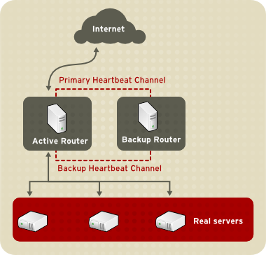
Figure 1.17. Two-Tier LVS Topology
Service requests arriving at an LVS router are addressed to a virtual IP address or VIP. This is a publicly-routable address that the administrator of the site associates with a fully-qualified domain name, such as www.example.com, and which is assigned to one or more virtual servers[1]. Note that a VIP address migrates from one LVS router to the other during a failover, thus maintaining a presence at that IP address, also known as floating IP addresses.
VIP addresses may be aliased to the same device that connects the LVS router to the public network. For instance, if eth0 is connected to the Internet, then multiple virtual servers can be aliased to
eth0:1. Alternatively, each virtual server can be associated with a separate device per service. For example, HTTP traffic can be handled on eth0:1, and FTP traffic can be handled on eth0:2.
Only one LVS router is active at a time. The role of the active LVS router is to redirect service requests from virtual IP addresses to the real servers. The redirection is based on one of eight load-balancing algorithms:
- Round-Robin Scheduling — Distributes each request sequentially around a pool of real servers. Using this algorithm, all the real servers are treated as equals without regard to capacity or load.
- Weighted Round-Robin Scheduling — Distributes each request sequentially around a pool of real servers but gives more jobs to servers with greater capacity. Capacity is indicated by a user-assigned weight factor, which is then adjusted up or down by dynamic load information. This is a preferred choice if there are significant differences in the capacity of real servers in a server pool. However, if the request load varies dramatically, a more heavily weighted server may answer more than its share of requests.
- Least-Connection — Distributes more requests to real servers with fewer active connections. This is a type of dynamic scheduling algorithm, making it a better choice if there is a high degree of variation in the request load. It is best suited for a real server pool where each server node has roughly the same capacity. If the real servers have varying capabilities, weighted least-connection scheduling is a better choice.
- Weighted Least-Connections (default) — Distributes more requests to servers with fewer active connections relative to their capacities. Capacity is indicated by a user-assigned weight, which is then adjusted up or down by dynamic load information. The addition of weighting makes this algorithm ideal when the real server pool contains hardware of varying capacity.
- Locality-Based Least-Connection Scheduling — Distributes more requests to servers with fewer active connections relative to their destination IPs. This algorithm is for use in a proxy-cache server cluster. It routes the packets for an IP address to the server for that address unless that server is above its capacity and has a server in its half load, in which case it assigns the IP address to the least loaded real server.
- Locality-Based Least-Connection Scheduling with Replication Scheduling — Distributes more requests to servers with fewer active connections relative to their destination IPs. This algorithm is also for use in a proxy-cache server cluster. It differs from Locality-Based Least-Connection Scheduling by mapping the target IP address to a subset of real server nodes. Requests are then routed to the server in this subset with the lowest number of connections. If all the nodes for the destination IP are above capacity, it replicates a new server for that destination IP address by adding the real server with the least connections from the overall pool of real servers to the subset of real servers for that destination IP. The most-loaded node is then dropped from the real server subset to prevent over-replication.
- Source Hash Scheduling — Distributes requests to the pool of real servers by looking up the source IP in a static hash table. This algorithm is for LVS routers with multiple firewalls.
Also, the active LVS router dynamically monitors the overall health of the specific services on the real servers through simple send/expect scripts. To aid in detecting the health of services that require dynamic data, such as HTTPS or SSL, you can also call external executables. If a service on a real server malfunctions, the active LVS router stops sending jobs to that server until it returns to normal operation.
The backup LVS router performs the role of a standby system. Periodically, the LVS routers exchange heartbeat messages through the primary external public interface and, in a failover situation, the private interface. Should the backup LVS router fail to receive a heartbeat message within an expected interval, it initiates a failover and assumes the role of the active LVS router. During failover, the backup LVS router takes over the VIP addresses serviced by the failed router using a technique known as ARP spoofing — where the backup LVS router announces itself as the destination for IP packets addressed to the failed node. When the failed node returns to active service, the backup LVS router assumes its backup role again.
The simple, two-tier configuration in Figure 1.17, “Two-Tier LVS Topology” is suited best for clusters serving data that does not change very frequently — such as static web pages — because the individual real servers do not automatically synchronize data among themselves.
1.8.2. Three-Tier LVS Topology
Figure 1.18, “Three-Tier LVS Topology” shows a typical three-tier LVS configuration. In the example, the active LVS router routes the requests from the public network (Internet) to the second tier — real servers. Each real server then accesses a shared data source of a Red Hat cluster in the third tier over the private network.
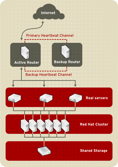
Figure 1.18. Three-Tier LVS Topology
This topology is suited well for busy FTP servers, where accessible data is stored on a central, highly available server and accessed by each real server via an exported NFS directory or Samba share. This topology is also recommended for websites that access a central, high-availability database for transactions. Additionally, using an active-active configuration with a Red Hat cluster, you can configure one high-availability cluster to serve both of these roles simultaneously.
1.8.3. Routing Methods
You can use Network Address Translation (NAT) routing or direct routing with LVS. The following sections briefly describe NAT routing and direct routing with LVS.
1.8.3.1. NAT Routing
Figure 1.19, “LVS Implemented with NAT Routing”, illustrates LVS using NAT routing to move requests between the Internet and a private network.
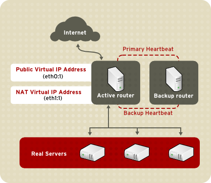
Figure 1.19. LVS Implemented with NAT Routing
In the example, there are two NICs in the active LVS router. The NIC for the Internet has a real IP address on eth0 and has a floating IP address aliased to eth0:1. The NIC for the private network interface has a real IP address on eth1 and has a floating IP address aliased to eth1:1. In the event of failover, the virtual interface facing the Internet and the private facing virtual interface are taken over by the backup LVS router simultaneously. All the real servers on the private network use the floating IP for the NAT router as their default route to communicate with the active LVS router so that their abilities to respond to requests from the Internet is not impaired.
In the example, the LVS router's public LVS floating IP address and private NAT floating IP address are aliased to two physical NICs. While it is possible to associate each floating IP address to its physical device on the LVS router nodes, having more than two NICs is not a requirement.
Using this topology, the active LVS router receives the request and routes it to the appropriate server. The real server then processes the request and returns the packets to the LVS router. The LVS router uses network address translation to replace the address of the real server in the packets with the LVS routers public VIP address. This process is called IP masquerading because the actual IP addresses of the real servers is hidden from the requesting clients.
Using NAT routing, the real servers can be any kind of computers running a variety operating systems. The main disadvantage of NAT routing is that the LVS router may become a bottleneck in large deployments because it must process outgoing and incoming requests.
1.8.3.2. Direct Routing
Direct routing provides increased performance benefits compared to NAT routing. Direct routing allows the real servers to process and route packets directly to a requesting user rather than passing outgoing packets through the LVS router. Direct routing reduces the possibility of network performance issues by relegating the job of the LVS router to processing incoming packets only.

Figure 1.20. LVS Implemented with Direct Routing
In a typical direct-routing LVS configuration, an LVS router receives incoming server requests through a virtual IP (VIP) and uses a scheduling algorithm to route the request to real servers. Each real server processes requests and sends responses directly to clients, bypassing the LVS routers. Direct routing allows for scalability in that real servers can be added without the added burden on the LVS router to route outgoing packets from the real server to the client, which can become a bottleneck under heavy network load.
While there are many advantages to using direct routing in LVS, there are limitations. The most common issue with direct routing and LVS is with Address Resolution Protocol (ARP).
In typical situations, a client on the Internet sends a request to an IP address. Network routers typically send requests to their destination by relating IP addresses to a machine's MAC address with ARP. ARP requests are broadcast to all connected machines on a network, and the machine with the correct IP/MAC address combination receives the packet. The IP/MAC associations are stored in an ARP cache, which is cleared periodically (usually every 15 minutes) and refilled with IP/MAC associations.
The issue with ARP requests in a direct-routing LVS configuration is that because a client request to an IP address must be associated with a MAC address for the request to be handled, the virtual IP address of the LVS router must also be associated to a MAC. However, because both the LVS router and the real servers have the same VIP, the ARP request is broadcast to all the nodes associated with the VIP. This can cause several problems, such as the VIP being associated directly to one of the real servers and processing requests directly, bypassing the LVS router completely and defeating the purpose of the LVS configuration. Using an LVS router with a powerful CPU that can respond quickly to client requests does not necessarily remedy this issue. If the LVS router is under heavy load, it may respond to the ARP request more slowly than an underutilized real server, which responds more quickly and is assigned the VIP in the ARP cache of the requesting client.
To solve this issue, the incoming requests should only associate the VIP to the LVS router, which will properly process the requests and send them to the real server pool. This can be done by using the
arptables packet-filtering tool.
1.8.4. Persistence and Firewall Marks
In certain situations, it may be desirable for a client to reconnect repeatedly to the same real server, rather than have an LVS load-balancing algorithm send that request to the best available server. Examples of such situations include multi-screen web forms, cookies, SSL, and FTP connections. In those cases, a client may not work properly unless the transactions are being handled by the same server to retain context. LVS provides two different features to handle this: persistence and firewall marks.
1.8.4.1. Persistence
When enabled, persistence acts like a timer. When a client connects to a service, LVS remembers the last connection for a specified period of time. If that same client IP address connects again within that period, it is sent to the same server it connected to previously — bypassing the load-balancing mechanisms. When a connection occurs outside the time window, it is handled according to the scheduling rules in place.
Persistence also allows you to specify a subnet mask to apply to the client IP address test as a tool for controlling what addresses have a higher level of persistence, thereby grouping connections to that subnet.
Grouping connections destined for different ports can be important for protocols that use more than one port to communicate, such as FTP. However, persistence is not the most efficient way to deal with the problem of grouping together connections destined for different ports. For these situations, it is best to use firewall marks.
1.8.4.2. Firewall Marks
Firewall marks are an easy and efficient way to a group ports used for a protocol or group of related protocols. For example, if LVS is deployed to run an e-commerce site, firewall marks can be used to bundle HTTP connections on port 80 and secure, HTTPS connections on port 443. By assigning the same firewall mark to the virtual server for each protocol, state information for the transaction can be preserved because the LVS router forwards all requests to the same real server after a connection is opened.
Because of its efficiency and ease-of-use, administrators of LVS should use firewall marks instead of persistence whenever possible for grouping connections. However, you should still add persistence to the virtual servers in conjunction with firewall marks to ensure the clients are reconnected to the same server for an adequate period of time.