
Chapter 1. Introduction
This guide provides information about constructing a spine-leaf network topology for your Red Hat OpenStack Platform environment. This includes a full end-to-end scenario and example files to help replicate a more extensive network topology within your own environment.
1.1. Spine-leaf networking
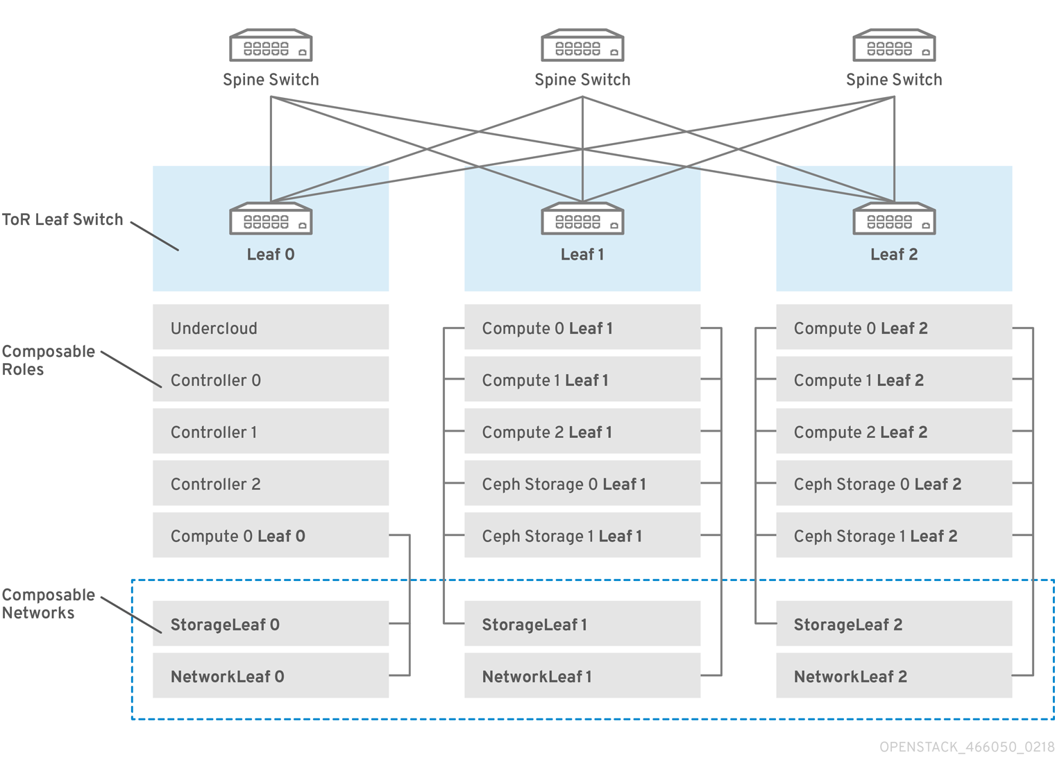
Red Hat OpenStack Platform has a composable network architecture that you can use to adapt your networking to the routed spine-leaf data center topology. In a practical application of routed spine-leaf, a leaf is represented as a composable Compute or Storage role usually in a data center rack, as shown in Figure 1.1, “Routed spine-leaf example”. The Leaf 0 rack has an undercloud node, Controller nodes, and Compute nodes. The composable networks are presented to the nodes, which have been assigned to composable roles. The following diagram contains the following configuration:
-
The
StorageLeafnetworks are presented to the Ceph storage and Compute nodes. -
The
NetworkLeafrepresents an example of any network you might want to compose.
Figure 1.1. Routed spine-leaf example
1.2. Spine-leaf network topology
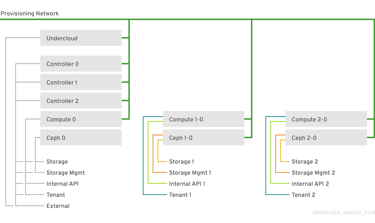
The spine-leaf scenario takes advantage of OpenStack Networking (neutron) functionality to define multiple subnets within segments of a single network. Each network uses a base network which acts as Leaf 0. The director creates Leaf 1 and Leaf 2 subnets as segments of the main network.
This scenario uses the following networks:
Table 1.1. Leaf 0 Networks (base networks)
| Network | Roles attached | Subnet |
|---|---|---|
| Provisioning / Ctlplane / Leaf0 | Controller, ComputeLeaf0, CephStorageLeaf0 | 192.168.10.0/24 |
| Storage | Controller, ComputeLeaf0, CephStorageLeaf0 | 172.16.0.0/24 |
| StorageMgmt | Controller, CephStorageLeaf0 | 172.17.0.0/24 |
| InternalApi | Controller, ComputeLeaf0 | 172.18.0.0/24 |
| Tenant | Controller, ComputeLeaf0 | 172.19.0.0/24 |
| External | Controller, ComputeLeaf0 | 10.1.1.0/24 |
Table 1.2. Leaf 1 Networks
| Network | Roles attached | Subnet |
|---|---|---|
| Provisioning / Ctlplane / Leaf1 | ComputeLeaf1, CephStorageLeaf1 | 192.168.11.0/24 |
| StorageLeaf1 | ComputeLeaf1, CephStorageLeaf1 | 172.16.1.0/24 |
| StorageMgmtLeaf1 | CephStorageLeaf1 | 172.17.1.0/24 |
| InternalApiLeaf1 | ComputeLeaf1 | 172.18.1.0/24 |
| TenantLeaf1 | ComputeLeaf1 | 172.19.1.0/24 |
Table 1.3. Leaf 2 Networks
| Network | Roles attached | Subnet |
|---|---|---|
| Provisioning / Ctlplane / Leaf2 | ComputeLeaf2, CephStorageLeaf2 | 192.168.12.0/24 |
| StorageLeaf2 | ComputeLeaf2, CephStorageLeaf2 | 172.16.2.0/24 |
| StorageMgmtLeaf2 | CephStorageLeaf2 | 172.17.2.0/24 |
| InternalApiLeaf2 | ComputeLeaf2 | 172.18.2.0/24 |
| TenantLeaf2 | ComputeLeaf2 | 172.19.2.0/24 |
1.3. Spine-leaf requirements
To deploy the overcloud on a network with a L3 routed architecture, complete the following prerequisite steps:
- Layer-3 routing
- Configure the routing of the network infrastructure to enable traffic between the different L2 segments. You can configure this routing statically or dynamically.
- DHCP-Relay
-
Each L2 segment not local to the undercloud must provide
dhcp-relay. You must forward DHCP requests to the undercloud on the provisioning network segment where the undercloud is connected.
The undercloud uses two DHCP servers. One for baremetal node introspection, and another for deploying overcloud nodes. Ensure that you read DHCP relay configuration to understand the requirements when you configure dhcp-relay.
1.4. Spine-leaf limitations
- Some roles, such as the Controller role, use virtual IP addresses and clustering. The mechanism behind this functionality requires L2 network connectivity between these nodes. You must place these nodes within the same leaf.
- Similar restrictions apply to Networker nodes. The network service implements highly-available default paths in the network with Virtual Router Redundancy Protocol (VRRP). Because VRRP uses a virtual router IP address, you must connect master and backup nodes to the same L2 network segment.
- When you use tenant or provider networks with VLAN segmentation, you must share the particular VLANs between all Networker and Compute nodes.
It is possible to configure the network service with multiple sets of Networker nodes. Each set of Networker nodes share routes for their networks, and VRRP provides highly-available default paths within each set of Networker nodes. In this type of configuration, all Networker nodes that share networks must be on the same L2 network segment.