
Chapter 8. Configuring physical switches for OpenStack Networking
This chapter documents the common physical switch configuration steps required for OpenStack Networking. Vendor-specific configuration is included for the following switches:
8.1. Planning your physical network environment
The physical network adapters in your OpenStack nodes carry different types of network traffic, such as instance traffic, storage data, or authentication requests. The type of traffic these NICs carry affects how you must configure the ports on the physical switch.
First, you must decide which physical NICs on your Compute node you want to carry which types of traffic. Then, when the NIC is cabled to a physical switch port, you must configure the switch port to allow trunked or general traffic.
For example, the following diagram depicts a Compute node with two NICs, eth0 and eth1. Each NIC is cabled to a Gigabit Ethernet port on a physical switch, with eth0 carrying instance traffic, and eth1 providing connectivity for OpenStack services:
Sample network layout
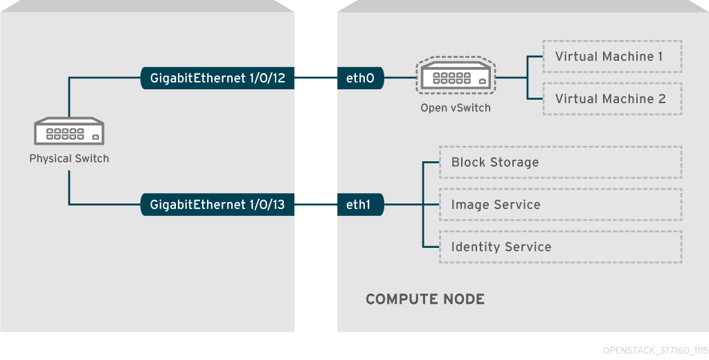
This diagram does not include any additional redundant NICs required for fault tolerance.
For information on network interface bonds, see the Network Interface Bonding chapter of the Advanced Overcloud Customization guide.
8.2. Configuring a Cisco Catalyst switch
8.2.1. About trunk ports
With OpenStack Networking you can connect instances to the VLANs that already exist on your physical network. The term trunk is used to describe a port that allows multiple VLANs to traverse through the same port. Using these ports, VLANs can span across multiple switches, including virtual switches. For example, traffic tagged as VLAN110 in the physical network reaches the Compute node, where the 8021q module directs the tagged traffic to the appropriate VLAN on the vSwitch.
8.2.2. Configuring trunk ports for a Cisco Catalyst switch
If using a Cisco Catalyst switch running Cisco IOS, you might use the following configuration syntax to allow traffic for VLANs 110 and 111 to pass through to your instances.
This configuration assumes that your physical node has an ethernet cable connected to interface GigabitEthernet1/0/12 on the physical switch.
ImportantThese values are examples. You must change the values in this example to match those in your environment. Copying and pasting these values into your switch configuration without adjustment can result in an unexpected outage.
interface GigabitEthernet1/0/12
  description Trunk to Compute Node
  spanning-tree portfast trunk
  switchport trunk encapsulation dot1q
  switchport mode trunk
  switchport trunk native vlan 2
  switchport trunk allowed vlan 2,110,111
Use the following list to understand these parameters:
Field Description interface GigabitEthernet1/0/12The switch port that the NIC of the X node connects to. Ensure that you replace the
GigabitEthernet1/0/12value with the correct port value for your environment. Use the show interface command to view a list of ports.description Trunk to Compute NodeA unique and descriptive value that you can use to identify this interface.
spanning-tree portfast trunkIf your environment uses STP, set this value to instruct Port Fast that this port is used to trunk traffic.
switchport trunk encapsulation dot1qEnables the 802.1q trunking standard (rather than ISL). This value varies depending on the configuration that your switch supports.
switchport mode trunkConfigures this port as a trunk port, rather than an access port, meaning that it allows VLAN traffic to pass through to the virtual switches.
switchport trunk native vlan 2Set a native VLAN to instruct the switch where to send untagged (non-VLAN) traffic.
switchport trunk allowed vlan 2,110,111Defines which VLANs are allowed through the trunk.
8.2.3. About access ports
Not all NICs on your Compute node carry instance traffic, and so you do not need to configure all NICs to allow multiple VLANs to pass through. Access ports require only one VLAN, and might fulfill other operational requirements, such as transporting management traffic or Block Storage data. These ports are commonly known as access ports and usually require a simpler configuration than trunk ports.
8.2.4. Configuring access ports for a Cisco Catalyst switch
Using the example from the Sample network layout diagram, GigabitEthernet1/0/13 (on a Cisco Catalyst switch) is configured as an access port for
eth1.In this configuration,your physical node has an ethernet cable connected to interface GigabitEthernet1/0/12 on the physical switch.
ImportantThese values are examples. You must change the values in this example to match those in your environment. Copying and pasting these values into your switch configuration without adjustment can result in an unexpected outage.
interface GigabitEthernet1/0/13
 description Access port for Compute Node
 switchport mode access
 switchport access vlan 200
 spanning-tree portfast
These settings are described below:
Field Description interface GigabitEthernet1/0/13The switch port that the NIC of the X node connects to. Ensure that you replace the
GigabitEthernet1/0/12value with the correct port value for your environment. Use the show interface command to view a list of ports.description Access port for Compute NodeA unique and descriptive value that you can use to identify this interface.
switchport mode accessConfigures this port as an access port, rather than a trunk port.
switchport access vlan 200Configures the port to allow traffic on VLAN 200. You must configure your Compute node with an IP address from this VLAN.
spanning-tree portfastIf using STP, set this value to instruct STP not to attempt to initialize this as a trunk, allowing for quicker port handshakes during initial connections (such as server reboot).
8.2.5. About LACP port aggregation
You can use LACP to bundle multiple physical NICs together to form a single logical channel. Also known as 802.3ad (or bonding mode 4 in Linux), LACP creates a dynamic bond for load-balancing and fault tolerance. You must configure LACP at both physical ends: on the physical NICs, and on the physical switch ports.
8.2.6. Configuring LACP on the physical NIC
Edit the /home/stack/network-environment.yaml file:
- type: linux_bond
  name: bond1
  mtu: 9000
  bonding_options:{get_param: BondInterfaceOvsOptions};
  members:
    - type: interface
      name: nic3
      mtu: 9000
      primary: true
    - type: interface
      name: nic4
      mtu: 9000
Configure the Open vSwitch bridge to use LACP:
BondInterfaceOvsOptions:
    "mode=802.3ad"
For information on configuring network bonds, see the Network Interface Bonding chapter of the Advanced Overcloud Customization guide.
8.2.7. Configuring LACP for a Cisco Catalyst switch
In this example, the Compute node has two NICs using VLAN 100:
- Physically connect both NICs on the Compute node to the switch (for example, ports 12 and 13).
Create the LACP port channel:
interface port-channel1
  switchport access vlan 100
  switchport mode access
  spanning-tree guard root
Configure switch ports 12 (Gi1/0/12) and 13 (Gi1/0/13):
sw01# config t
Enter configuration commands, one per line.  End with CNTL/Z.

sw01(config) interface GigabitEthernet1/0/12
   switchport access vlan 100
   switchport mode access
   speed 1000
   duplex full
   channel-group 10 mode active
   channel-protocol lacp

interface GigabitEthernet1/0/13
  switchport access vlan 100
  switchport mode access
  speed 1000
  duplex full
  channel-group 10 mode active
  channel-protocol lacp
Review your new port channel. The resulting output lists the new port-channel
Po1, with member portsGi1/0/12andGi1/0/13:sw01# show etherchannel summary <snip> Number of channel-groups in use: 1 Number of aggregators: 1 Group Port-channel Protocol Ports ------+-------------+-----------+----------------------------------------------- 1 Po1(SD) LACP Gi1/0/12(D) Gi1/0/13(D)
NoteRemember to apply your changes by copying the running-config to the startup-config:
copy running-config startup-config.
8.2.8. About MTU settings
You must adjust your MTU size for certain types of network traffic. For example, jumbo frames (9000 bytes) are required for certain NFS or iSCSI traffic.
You must change MTU settings from end-to-end on all hops that the traffic is expected to pass through, including any virtual switches. For information on changing the MTU in your OpenStack environment, see Chapter 9, Configure maximum transmission unit (MTU) settings.
8.2.9. Configuring MTU settings for a Cisco Catalyst switch
Complete the steps in this example procedure to enable jumbo frames on your Cisco Catalyst 3750 switch.
Review the current MTU settings:
sw01# show system mtu

System MTU size is 1600 bytes
System Jumbo MTU size is 1600 bytes
System Alternate MTU size is 1600 bytes
Routing MTU size is 1600 bytes
MTU settings are changed switch-wide on 3750 switches, and not for individual interfaces. Run the following commands to configure the switch to use jumbo frames of 9000 bytes. You might prefer to configure the MTU settings for individual interfaces, if your switch supports this feature.
sw01# config t
Enter configuration commands, one per line.  End with CNTL/Z.

sw01(config)# system mtu jumbo 9000
Changes to the system jumbo MTU will not take effect until the next reload is done
NoteRemember to save your changes by copying the running-config to the startup-config:
copy running-config startup-config.Reload the switch to apply the change.
ImportantReloading the switch causes a network outage for any devices that are dependent on the switch. Therefore, reload the switch only during a scheduled maintenance period.
sw01# reload
Proceed with reload? [confirm]
After the switch reloads, confirm the new jumbo MTU size.
The exact output may differ depending on your switch model. For example, System MTU might apply to non-Gigabit interfaces, and Jumbo MTU might describe all Gigabit interfaces.
sw01# show system mtu

System MTU size is 1600 bytes
System Jumbo MTU size is 9000 bytes
System Alternate MTU size is 1600 bytes
Routing MTU size is 1600 bytes
8.2.10. About LLDP discovery
The ironic-python-agent service listens for LLDP packets from connected switches. The collected information can include the switch name, port details, and available VLANs. Similar to Cisco Discovery Protocol (CDP), LLDP assists with the discovery of physical hardware during the director introspection process.
8.2.11. Configuring LLDP for a Cisco Catalyst switch
Run the
lldp runcommand to enable LLDP globally on your Cisco Catalyst switch:sw01# config t Enter configuration commands, one per line. End with CNTL/Z. sw01(config)# lldp run
View any neighboring LLDP-compatible devices:
sw01# show lldp neighbor
Capability codes:
    (R) Router, (B) Bridge, (T) Telephone, (C) DOCSIS Cable Device
    (W) WLAN Access Point, (P) Repeater, (S) Station, (O) Other

Device ID           Local Intf     Hold-time  Capability      Port ID
DEP42037061562G3     Gi1/0/11       180        B,T             422037061562G3:P1

Total entries displayed: 1
Remember to save your changes by copying the running-config to the startup-config: copy running-config startup-config.
8.3. Configuring a Cisco Nexus switch
8.3.1. About trunk ports
With OpenStack Networking you can connect instances to the VLANs that already exist on your physical network. The term trunk is used to describe a port that allows multiple VLANs to traverse through the same port. Using these ports, VLANs can span across multiple switches, including virtual switches. For example, traffic tagged as VLAN110 in the physical network reaches the Compute node, where the 8021q module directs the tagged traffic to the appropriate VLAN on the vSwitch.
8.3.2. Configuring trunk ports for a Cisco Nexus switch
If using a Cisco Nexus you might use the following configuration syntax to allow traffic for VLANs 110 and 111 to pass through to your instances.
This configuration assumes that your physical node has an ethernet cable connected to interface
Ethernet1/12on the physical switch.ImportantThese values are examples. You must change the values in this example to match those in your environment. Copying and pasting these values into your switch configuration without adjustment can result in an unexpected outage.
interface Ethernet1/12
  description Trunk to Compute Node
  switchport mode trunk
  switchport trunk allowed vlan 2,110,111
  switchport trunk native vlan 2
end
8.3.3. About access ports
Not all NICs on your Compute node carry instance traffic, and so you do not need to configure all NICs to allow multiple VLANs to pass through. Access ports require only one VLAN, and might fulfill other operational requirements, such as transporting management traffic or Block Storage data. These ports are commonly known as access ports and usually require a simpler configuration than trunk ports.
8.3.4. Configuring access ports for a Cisco Nexus switch
Using the example from the Sample network layout diagram, Ethernet1/13 (on a Cisco Nexus switch) is configured as an access port for
eth1. This configuration assumes that your physical node has an ethernet cable connected to interfaceEthernet1/13on the physical switch.ImportantThese values are examples. You must change the values in this example to match those in your environment. Copying and pasting these values into your switch configuration without adjustment can result in an unexpected outage.
interface Ethernet1/13
 description Access port for Compute Node
 switchport mode access
 switchport access vlan 200
8.3.5. About LACP port aggregation
You can use LACP to bundle multiple physical NICs together to form a single logical channel. Also known as 802.3ad (or bonding mode 4 in Linux), LACP creates a dynamic bond for load-balancing and fault tolerance. You must configure LACP at both physical ends: on the physical NICs, and on the physical switch ports.
8.3.6. Configuring LACP on the physical NIC
Edit the /home/stack/network-environment.yaml file:
- type: linux_bond
  name: bond1
  mtu: 9000
  bonding_options:{get_param: BondInterfaceOvsOptions};
  members:
    - type: interface
      name: nic3
      mtu: 9000
      primary: true
    - type: interface
      name: nic4
      mtu: 9000
Configure the Open vSwitch bridge to use LACP:
BondInterfaceOvsOptions:
    "mode=802.3ad"
For information on configuring network bonds, see the Network Interface Bonding chapter of the Advanced Overcloud Customization guide.
8.3.7. Configuring LACP for a Cisco Nexus switch
In this example, the Compute node has two NICs using VLAN 100:
- Physically connect the Compute node NICs to the switch (for example, ports 12 and 13).
Confirm that LACP is enabled:
(config)# show feature | include lacp
lacp                  1         enabled
Configure ports 1/12 and 1/13 as access ports, and as members of a channel group.
Depending on your deployment, you can deploy trunk interfaces rather than access interfaces.
For example, for Cisco UCI the NICs are virtual interfaces, so you might prefer to configure access ports exclusively. Often these interfaces contain VLAN tagging configurations.
interface Ethernet1/13
 description Access port for Compute Node
 switchport mode access
 switchport access vlan 200
 channel-group 10 mode active

interface Ethernet1/13
 description Access port for Compute Node
 switchport mode access
 switchport access vlan 200
 channel-group 10 mode active
8.3.8. About MTU settings
You must adjust your MTU size for certain types of network traffic. For example, jumbo frames (9000 bytes) are required for certain NFS or iSCSI traffic.
You must change MTU settings from end-to-end on all hops that the traffic is expected to pass through, including any virtual switches. For information on changing the MTU in your OpenStack environment, see Chapter 9, Configure maximum transmission unit (MTU) settings.
8.3.9. Configuring MTU settings for a Cisco Nexus 7000 switch
Apply MTU settings to a single interface on 7000-series switches.
Run the following commands to configure interface 1/12 to use jumbo frames of 9000 bytes:
interface ethernet 1/12
  mtu 9216
  exit
8.3.10. About LLDP discovery
The ironic-python-agent service listens for LLDP packets from connected switches. The collected information can include the switch name, port details, and available VLANs. Similar to Cisco Discovery Protocol (CDP), LLDP assists with the discovery of physical hardware during the director introspection process.
8.3.11. Configuring LLDP for a Cisco Nexus 7000 switch
You can enable LLDP for individual interfaces on Cisco Nexus 7000-series switches:
interface ethernet 1/12
  lldp transmit
  lldp receive
  no lacp suspend-individual
  no lacp graceful-convergence

interface ethernet 1/13
  lldp transmit
  lldp receive
  no lacp suspend-individual
  no lacp graceful-convergence
Remember to save your changes by copying the running-config to the startup-config: copy running-config startup-config.
8.4. Configuring a Cumulus Linux switch
8.4.1. About trunk ports
With OpenStack Networking you can connect instances to the VLANs that already exist on your physical network. The term trunk is used to describe a port that allows multiple VLANs to traverse through the same port. Using these ports, VLANs can span across multiple switches, including virtual switches. For example, traffic tagged as VLAN110 in the physical network reaches the Compute node, where the 8021q module directs the tagged traffic to the appropriate VLAN on the vSwitch.
8.4.2. Configuring trunk ports for a Cumulus Linux switch
Use the following configuration syntax to allow traffic for VLANs 100 and 200 to pass through to your instances.
This configuration assumes that your physical node has transceivers connected to switch ports swp1 and swp2 on the physical switch.
ImportantThese values are examples. You must change the values in this example to match those in your environment. Copying and pasting these values into your switch configuration without adjustment can result in an unexpected outage.
auto bridge
iface bridge
  bridge-vlan-aware yes
  bridge-ports glob swp1-2
  bridge-vids 100 200
8.4.3. About access ports
Not all NICs on your Compute node carry instance traffic, and so you do not need to configure all NICs to allow multiple VLANs to pass through. Access ports require only one VLAN, and might fulfill other operational requirements, such as transporting management traffic or Block Storage data. These ports are commonly known as access ports and usually require a simpler configuration than trunk ports.
8.4.4. Configuring access ports for a Cumulus Linux switch
Using the example from the Sample network layout diagram,
swp1(on a Cumulus Linux switch) is configured as an access port.This configuration assumes that your physical node has an ethernet cable connected to the interface on the physical switch. Cumulus Linux switches use
ethfor management interfaces andswpfor access/trunk ports.ImportantThese values are examples. You must change the values in this example to match those in your environment. Copying and pasting these values into your switch configuration without adjustment can result in an unexpected outage.
auto bridge
iface bridge
  bridge-vlan-aware yes
  bridge-ports glob swp1-2
  bridge-vids 100 200


auto swp1
iface swp1
  bridge-access 100


auto swp2
iface swp2
  bridge-access 200
8.4.5. About LACP port aggregation
You can use LACP to bundle multiple physical NICs together to form a single logical channel. Also known as 802.3ad (or bonding mode 4 in Linux), LACP creates a dynamic bond for load-balancing and fault tolerance. You must configure LACP at both physical ends: on the physical NICs, and on the physical switch ports.
8.4.6. About MTU settings
You must adjust your MTU size for certain types of network traffic. For example, jumbo frames (9000 bytes) are required for certain NFS or iSCSI traffic.
You must change MTU settings from end-to-end on all hops that the traffic is expected to pass through, including any virtual switches. For information on changing the MTU in your OpenStack environment, see Chapter 9, Configure maximum transmission unit (MTU) settings.
8.4.7. Configuring MTU settings for a Cumulus Linux switch
This example enables jumbo frames on your Cumulus Linux switch.
auto swp1
iface swp1
  mtu 9000
NoteRemember to apply your changes by reloading the updated configuration:
sudo ifreload -a
8.4.8. About LLDP discovery
The ironic-python-agent service listens for LLDP packets from connected switches. The collected information can include the switch name, port details, and available VLANs. Similar to Cisco Discovery Protocol (CDP), LLDP assists with the discovery of physical hardware during the director introspection process.
8.4.9. Configuring LLDP for a Cumulus Linux switch
By default, the LLDP service lldpd runs as a daemon and starts when the switch boots.
To view all LLDP neighbors on all ports/interfaces, run the following command:
cumulus@switch$ netshow lldp
Local Port  Speed  Mode         Remote Port   Remote Host Summary
----------  ---    ---------    -----  -----  ----------- --------
eth0        10G    Mgmt         ====   swp6   mgmt-sw     IP: 10.0.1.11/24
swp51       10G    Interface/L3 ====   swp1   spine01     IP: 10.0.0.11/32
swp52       10G    Interface/L  ====   swp1   spine02     IP: 10.0.0.11/32
8.5. Configuring a Extreme Exos switch
8.5.1. About trunk ports
With OpenStack Networking you can connect instances to the VLANs that already exist on your physical network. The term trunk is used to describe a port that allows multiple VLANs to traverse through the same port. Using these ports, VLANs can span across multiple switches, including virtual switches. For example, traffic tagged as VLAN110 in the physical network reaches the Compute node, where the 8021q module directs the tagged traffic to the appropriate VLAN on the vSwitch.
8.5.2. Configuring trunk ports on an Extreme Networks EXOS switch
If using an X-670 series switch, refer to the following example to allow traffic for VLANs 110 and 111 to pass through to your instances.
This configuration assumes that your physical node has an ethernet cable connected to interface 24 on the physical switch. In this example, DATA and MNGT are the VLAN names.
ImportantThese values are examples. You must change the values in this example to match those in your environment. Copying and pasting these values into your switch configuration without adjustment can result in an unexpected outage.
#create vlan DATA tag 110
#create vlan MNGT tag 111
#configure vlan DATA add ports 24 tagged
#configure vlan MNGT add ports 24 tagged
8.5.3. About access ports
Not all NICs on your Compute node carry instance traffic, and so you do not need to configure all NICs to allow multiple VLANs to pass through. Access ports require only one VLAN, and might fulfill other operational requirements, such as transporting management traffic or Block Storage data. These ports are commonly known as access ports and usually require a simpler configuration than trunk ports.
8.5.4. Configuring access ports for an Extreme Networks EXOS switch
In this configuration example, on a Extreme Networks X-670 series switch,
10is used as an access port foreth1.This configuration assumes that your physical node has an ethernet cable connected to interface
10on the physical switch.ImportantThese values are examples. You must change the values in this example to match those in your environment. Copying and pasting these values into your switch configuration without adjustment can result in an unexpected outage.
create vlan VLANNAME tag NUMBER
configure vlan Default delete ports PORTSTRING
configure vlan VLANNAME add ports PORTSTRING untagged
For example:
#create vlan DATA tag 110
#configure vlan Default delete ports 10
#configure vlan DATA add ports 10 untagged
8.5.5. About LACP port aggregation
You can use LACP to bundle multiple physical NICs together to form a single logical channel. Also known as 802.3ad (or bonding mode 4 in Linux), LACP creates a dynamic bond for load-balancing and fault tolerance. You must configure LACP at both physical ends: on the physical NICs, and on the physical switch ports.
8.5.6. Configuring LACP on the physical NIC
Edit the /home/stack/network-environment.yaml file:
- type: linux_bond
  name: bond1
  mtu: 9000
  bonding_options:{get_param: BondInterfaceOvsOptions};
  members:
    - type: interface
      name: nic3
      mtu: 9000
      primary: true
    - type: interface
      name: nic4
      mtu: 9000
Configure the Open vSwitch bridge to use LACP:
BondInterfaceOvsOptions:
    "mode=802.3ad"
For information on configuring network bonds, see the Network Interface Bonding chapter of the Advanced Overcloud Customization guide.
8.5.7. Configuring LACP on an Extreme Networks EXOS switch
In this example, the Compute node has two NICs using VLAN 100:
enable sharing MASTERPORT grouping ALL_LAG_PORTS lacp
configure vlan VLANNAME add ports PORTSTRING tagged
For example:
#enable sharing 11 grouping 11,12 lacp
#configure vlan DATA add port 11 untagged
NoteYou might need to adjust the timeout period in the LACP negotiation script. For more information, see https://gtacknowledge.extremenetworks.com/articles/How_To/LACP-configured-ports-interfere-with-PXE-DHCP-on-servers
8.5.8. About MTU settings
You must adjust your MTU size for certain types of network traffic. For example, jumbo frames (9000 bytes) are required for certain NFS or iSCSI traffic.
You must change MTU settings from end-to-end on all hops that the traffic is expected to pass through, including any virtual switches. For information on changing the MTU in your OpenStack environment, see Chapter 9, Configure maximum transmission unit (MTU) settings.
8.5.9. Configuring MTU settings on an Extreme Networks EXOS switch
Run the commands in this example to enable jumbo frames on an Extreme Networks EXOS switch and configure support for forwarding IP packets with 9000 bytes:
enable jumbo-frame ports PORTSTRING
configure ip-mtu 9000 vlan VLANNAME
For example:
# enable jumbo-frame ports 11
# configure ip-mtu 9000 vlan DATA
8.5.10. About LLDP discovery
The ironic-python-agent service listens for LLDP packets from connected switches. The collected information can include the switch name, port details, and available VLANs. Similar to Cisco Discovery Protocol (CDP), LLDP assists with the discovery of physical hardware during the director introspection process.
8.5.11. Configuring LLDP settings on an Extreme Networks EXOS switch
-
In this example, LLDP is enabled on an Extreme Networks EXOS switch.
11represents the port string:
enable lldp ports 11
8.6. Configuring a Juniper EX Series switch
8.6.1. About trunk ports
With OpenStack Networking you can connect instances to the VLANs that already exist on your physical network. The term trunk is used to describe a port that allows multiple VLANs to traverse through the same port. Using these ports, VLANs can span across multiple switches, including virtual switches. For example, traffic tagged as VLAN110 in the physical network reaches the Compute node, where the 8021q module directs the tagged traffic to the appropriate VLAN on the vSwitch.
8.6.2. Configuring trunk ports for a Juniper EX Series switch
If using a Juniper EX series switch running Juniper JunOS, use the following configuration syntax to allow traffic for VLANs 110 and 111 to pass through to your instances.
This configuration assumes that your physical node has an ethernet cable connected to interface ge-1/0/12 on the physical switch.
ImportantThese values are examples. You must change the values in this example to match those in your environment. Copying and pasting these values into your switch configuration without adjustment can result in an unexpected outage.
 ge-1/0/12 {
          description Trunk to Compute Node;
              unit 0 {
                  family ethernet-switching {
                      port-mode trunk;
                      vlan {
                          members [110 111];
                           }
                      native-vlan-id 2;
                  }
              }
}
8.6.3. About access ports
Not all NICs on your Compute node carry instance traffic, and so you do not need to configure all NICs to allow multiple VLANs to pass through. Access ports require only one VLAN, and might fulfill other operational requirements, such as transporting management traffic or Block Storage data. These ports are commonly known as access ports and usually require a simpler configuration than trunk ports.
8.6.4. Configuring access ports for a Juniper EX Series switch
This example on, a Juniper EX series switch, shows
ge-1/0/13as an access port foreth1.This configuration assumes that your physical node has an ethernet cable connected to interface
ge-1/0/13on the physical switch.ImportantThese values are examples. You must change the values in this example to match those in your environment. Copying and pasting these values into your switch configuration without adjustment can result in an unexpected outage.
 ge-1/0/13 {
          description Access port for Compute Node
              unit 0 {
                  family ethernet-switching {
                      port-mode access;
                      vlan {
                          members 200;
                           }
                      native-vlan-id 2;
                  }
              }
}
8.6.5. About LACP port aggregation
You can use LACP to bundle multiple physical NICs together to form a single logical channel. Also known as 802.3ad (or bonding mode 4 in Linux), LACP creates a dynamic bond for load-balancing and fault tolerance. You must configure LACP at both physical ends: on the physical NICs, and on the physical switch ports.
8.6.6. Configuring LACP on the physical NIC
Edit the /home/stack/network-environment.yaml file:
- type: linux_bond
  name: bond1
  mtu: 9000
  bonding_options:{get_param: BondInterfaceOvsOptions};
  members:
    - type: interface
      name: nic3
      mtu: 9000
      primary: true
    - type: interface
      name: nic4
      mtu: 9000
Configure the Open vSwitch bridge to use LACP:
BondInterfaceOvsOptions:
    "mode=802.3ad"
For information on configuring network bonds, see the Network Interface Bonding chapter of the Advanced Overcloud Customization guide.
8.6.7. Configuring LACP for a Juniper EX Series switch
In this example, the Compute node has two NICs using VLAN 100.
- Physically connect the Compute node’s two NICs to the switch (for example, ports 12 and 13).
Create the port aggregate:
chassis {
    aggregated-devices {
        ethernet {
            device-count 1;
        }
    }
}
Configure switch ports 12 (ge-1/0/12) and 13 (ge-1/0/13) to join the port aggregate
ae1:interfaces { ge-1/0/12 { gigether-options { 802.3ad ae1; } } ge-1/0/13 { gigether-options { 802.3ad ae1; } } }NoteFor Red Hat OpenStack Platform director deployments, in order to PXE boot from the bond, you must configure one of the bond members as lacp force-up toensure that only one bond member comes up during introspection and first boot. The bond member that you configure with lacp force-up must be the same bond member that has the MAC address in instackenv.json (the MAC address known to ironic must be the same MAC address configured with force-up).
Enable LACP on port aggregate
ae1:interfaces { ae1 { aggregated-ether-options { lacp { active; } } } }Add aggregate
ae1to VLAN 100:interfaces { ae1 { vlan-tagging; native-vlan-id 2; unit 100 { vlan-id 100; } } }Review your new port channel. The resulting output lists the new port aggregate
ae1with member portsge-1/0/12andge-1/0/13:> show lacp statistics interfaces ae1 Aggregated interface: ae1 LACP Statistics: LACP Rx LACP Tx Unknown Rx Illegal Rx ge-1/0/12 0 0 0 0 ge-1/0/13 0 0 0 0
NoteRemember to apply your changes by running the
commitcommand.
8.6.8. About MTU settings
You must adjust your MTU size for certain types of network traffic. For example, jumbo frames (9000 bytes) are required for certain NFS or iSCSI traffic.
You must change MTU settings from end-to-end on all hops that the traffic is expected to pass through, including any virtual switches. For information on changing the MTU in your OpenStack environment, see Chapter 9, Configure maximum transmission unit (MTU) settings.
8.6.9. Configuring MTU settings for a Juniper EX Series switch
This example enables jumbo frames on your Juniper EX4200 switch.
The MTU value is calculated differently depending on whether you are using Juniper or Cisco devices. For example, 9216 on Juniper would equal to 9202 for Cisco. The extra bytes are used for L2 headers, where Cisco adds this automatically to the MTU value specified, but the usable MTU will be 14 bytes smaller than specified when using Juniper. So in order to support an MTU of 9000 on the VLANs, the MTU of 9014 would have to be configured on Juniper.
For Juniper EX series switches, MTU settings are set for individual interfaces. These commands configure jumbo frames on the
ge-1/0/14andge-1/0/15ports:set interfaces ge-1/0/14 mtu 9216 set interfaces ge-1/0/15 mtu 9216
NoteRemember to save your changes by running the
commitcommand.If using a LACP aggregate, you will need to set the MTU size there, and not on the member NICs. For example, this setting configures the MTU size for the ae1 aggregate:
set interfaces ae1 mtu 9216
8.6.10. About LLDP discovery
The ironic-python-agent service listens for LLDP packets from connected switches. The collected information can include the switch name, port details, and available VLANs. Similar to Cisco Discovery Protocol (CDP), LLDP assists with the discovery of physical hardware during the director introspection process.
8.6.11. Configuring LLDP for a Juniper EX Series switch
You can enable LLDP globally for all interfaces, or just for individual ones:
Use the following too enable LLDP globally on your Juniper EX 4200 switch:
lldp {
	interface all{
		enable;
	}
	}
}
Use the following to enable LLDP for the single interface
ge-1/0/14:lldp { interface ge-1/0/14{ enable; } } }NoteRemember to apply your changes by running the
commitcommand.