
Red Hat Training
A Red Hat training course is available for Red Hat OpenStack Platform
Chapter 7. Connecting an instance to the physical network
This chapter contains information about using provider networks to connect instances directly to an external network.
7.1. Overview of the OpenStack Networking topology
OpenStack Networking (neutron) has two categories of services distributed across a number of node types.
- Neutron server - This service runs the OpenStack Networking API server, which provides the API for end-users and services to interact with OpenStack Networking. This server also integrates with the underlying database to store and retrieve project network, router, and loadbalancer details, among others.
Neutron agents - These are the services that perform the network functions for OpenStack Networking:
-
neutron-dhcp-agent- manages DHCP IP addressing for project private networks. -
neutron-l3-agent- performs layer 3 routing between project private networks, the external network, and others.
-
-
Compute node - This node hosts the hypervisor that runs the virtual machines, also known as instances. A Compute node must be wired directly to the network in order to provide external connectivity for instances. This node is typically where the l2 agents run, such as
neutron-openvswitch-agent.
Additional resources
7.2. Placement of OpenStack Networking services
The OpenStack Networking services can either run together on the same physical server, or on separate dedicated servers, which are named according to their roles:
- Controller node - The server that runs API service.
- Network node - The server that runs the OpenStack Networking agents.
- Compute node - The hypervisor server that hosts the instances.
The steps in this chapter apply to an environment that contains these three node types. If your deployment has both the Controller and Network node roles on the same physical node, then you must perform the steps from both sections on that server. This also applies for a High Availability (HA) environment, where all three nodes might be running the Controller node and Network node services with HA. As a result, you must complete the steps in sections applicable to Controller and Network nodes on all three nodes.
Additional resources
7.3. Configuring flat provider networks
You can use flat provider networks to connect instances directly to the external network. This is useful if you have multiple physical networks and separate physical interfaces, and intend to connect each Compute and Network node to those external networks.
Prerequisites
You have multiple physical networks.
This example uses physical networks called
physnet1, andphysnet2, respectively.You have separate physical interfaces.
This example uses separate physical interfaces,
eth0andeth1, respectively.
Procedure
On the undercloud host, logged in as the stack user, create a custom YAML environment file.
Example
$ vi /home/stack/templates/my-modules-environment.yaml
TipThe Red Hat OpenStack Platform Orchestration service (heat) uses a set of plans called templates to install and configure your environment. You can customize aspects of the overcloud with a custom environment file, which is a special type of template that provides customization for your orchestration templates.
In the YAML environment file under
parameter_defaults, use theNeutronBridgeMappingsto specify which OVS bridges are used for accessing external networks.Example
parameter_defaults:
  NeutronBridgeMappings: 'physnet1:br-net1,physnet2:br-net2'
In the custom NIC configuration template for the Controller and Compute nodes, configure the bridges with interfaces attached.
Example
...
              - type: ovs_bridge
                name: br-net1
                mtu: 1500
                use_dhcp: false
                members:
                - type: interface
                  name: eth0
                  mtu: 1500
                  use_dhcp: false
                  primary: true
              - type: ovs_bridge
                name: br-net2
                mtu: 1500
                use_dhcp: false
                members:
                - type: interface
                  name: eth1
                  mtu: 1500
                  use_dhcp: false
                  primary: true
...
Run the
openstack overcloud deploycommand and include the templates and the environment files, including this modified custom NIC template and the new environment file.ImportantThe order of the environment files is important because the parameters and resources defined in subsequent environment files take precedence.
Example
$ openstack overcloud deploy --templates \
-e [your-environment-files] \
-e /usr/share/openstack-tripleo-heat-templates/environments/services/my-neutron-environment.yaml
Verification steps
Create an external network (
public1) as a flat network and associate it with the configured physical network (physnet1).Configure it as a shared network (using
--share) to let other users create VM instances that connect to the external network directly.Example
# openstack network create --share --provider-network-type flat --provider-physical-network physnet1 --external public01
Create a subnet (
public_subnet) using theopenstack subnet createcommand.Example
# openstack subnet create --no-dhcp --allocation-pool start=192.168.100.20,end=192.168.100.100 --gateway 192.168.100.1 --network public01 public_subnet
Create a VM instance and connect it directly to the newly-created external network.
Example
$ openstack server create --image rhel --flavor my_flavor --network public01 my_instance
Additional resources
- Custom network interface templates in the Advanced Overcloud Customization guide
- Environment files in the Advanced Overcloud Customization guide
- Including Environment Files in Overcloud Creation in the Advanced Overcloud Customization guide
- network create in the Command Line Interface Reference
- subnet create in the Command Line Interface Reference
- server create in the Command Line Interface Reference
7.4. How does the flat provider network packet flow work?
This section describes in detail how traffic flows to and from an instance with flat provider network configuration.
The flow of outgoing traffic in a flat provider network
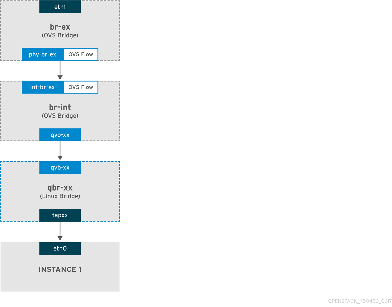
The following diagram describes the packet flow for traffic leaving an instance and arriving directly at an external network. After you configure the br-ex external bridge, add the physical interface to the bridge, and spawn an instance to a Compute node, the resulting configuration of interfaces and bridges resembles the configuration in the following diagram (if using the iptables_hybrid firewall driver):

-
Packets leave the
eth0interface of the instance and arrive at the linux bridgeqbr-xx. -
Bridge
qbr-xxis connected tobr-intusing veth pairqvb-xx <-> qvo-xxx. This is because the bridge is used to apply the inbound/outbound firewall rules defined by the security group. -
Interface
qvb-xxis connected to theqbr-xxlinux bridge, andqvoxxis connected to thebr-intOpen vSwitch (OVS) bridge.
An example configuration of `qbr-xx`Linux bridge:
 # brctl show
qbr269d4d73-e7		8000.061943266ebb	no		qvb269d4d73-e7
							tap269d4d73-e7
The configuration of qvo-xx on br-int:
 # ovs-vsctl show
  Bridge br-int
        fail_mode: secure
            Interface "qvof63599ba-8f"
        Port "qvo269d4d73-e7"
            tag: 5
            Interface "qvo269d4d73-e7"
Port qvo-xx is tagged with the internal VLAN tag associated with the flat provider network. In this example, the VLAN tag is 5. When the packet reaches qvo-xx, the VLAN tag is appended to the packet header.
The packet is then moved to the br-ex OVS bridge using the patch-peer int-br-ex <-> phy-br-ex.
Example configuration of the patch-peer on br-int:
 # ovs-vsctl show
    Bridge br-int
        fail_mode: secure
       Port int-br-ex
            Interface int-br-ex
                type: patch
                options: {peer=phy-br-ex}
Example configuration of the patch-peer on br-ex:
    Bridge br-ex
        Port phy-br-ex
            Interface phy-br-ex
                type: patch
                options: {peer=int-br-ex}
        Port br-ex
            Interface br-ex
                type: internal
When this packet reaches phy-br-ex on br-ex, an OVS flow inside br-ex strips the VLAN tag (5) and forwards it to the physical interface.
In the following example, the output shows the port number of phy-br-ex as 2.
 # ovs-ofctl show br-ex
OFPT_FEATURES_REPLY (xid=0x2): dpid:00003440b5c90dc6
n_tables:254, n_buffers:256
capabilities: FLOW_STATS TABLE_STATS PORT_STATS QUEUE_STATS ARP_MATCH_IP
actions: OUTPUT SET_VLAN_VID SET_VLAN_PCP STRIP_VLAN SET_DL_SRC SET_DL_DST SET_NW_SRC SET_NW_DST SET_NW_TOS SET_TP_SRC SET_TP_DST ENQUEUE

 2(phy-br-ex): addr:ba:b5:7b:ae:5c:a2
     config:     0
     state:      0
     speed: 0 Mbps now, 0 Mbps max
The following output shows any packet that arrives on phy-br-ex (in_port=2) with a VLAN tag of 5 (dl_vlan=5). In addition, an OVS flow in br-ex strips the VLAN tag and forwards the packet to the physical interface.
# ovs-ofctl dump-flows br-ex
NXST_FLOW reply (xid=0x4):
 cookie=0x0, duration=4703.491s, table=0, n_packets=3620, n_bytes=333744, idle_age=0, priority=1 actions=NORMAL
 cookie=0x0, duration=3890.038s, table=0, n_packets=13, n_bytes=1714, idle_age=3764, priority=4,in_port=2,dl_vlan=5 actions=strip_vlan,NORMAL
 cookie=0x0, duration=4702.644s, table=0, n_packets=10650, n_bytes=447632, idle_age=0, priority=2,in_port=2 actions=drop
If the physical interface is another VLAN-tagged interface, then the physical interface adds the tag to the packet.
The flow of incoming traffic in a flat provider network
This section contains information about the flow of incoming traffic from the external network until it arrives at the interface of the instance.
-
Incoming traffic arrives at
eth1on the physical node. -
The packet passes to the
br-exbridge. -
The packet moves to
br-intvia the patch-peerphy-br-ex <--> int-br-ex.
In the following example, int-br-ex uses port number 15. See the entry containing 15(int-br-ex):
 # ovs-ofctl show br-int
OFPT_FEATURES_REPLY (xid=0x2): dpid:00004e67212f644d
n_tables:254, n_buffers:256
capabilities: FLOW_STATS TABLE_STATS PORT_STATS QUEUE_STATS ARP_MATCH_IP
actions: OUTPUT SET_VLAN_VID SET_VLAN_PCP STRIP_VLAN SET_DL_SRC SET_DL_DST SET_NW_SRC SET_NW_DST SET_NW_TOS SET_TP_SRC SET_TP_DST ENQUEUE
 15(int-br-ex): addr:12:4e:44:a9:50:f4
     config:     0
     state:      0
     speed: 0 Mbps now, 0 Mbps max
Observing the traffic flow on br-int
-
When the packet arrives at
int-br-ex, an OVS flow rule within thebr-intbridge amends the packet to add the internal VLAN tag5. See the entry foractions=mod_vlan_vid:5:
 # ovs-ofctl dump-flows br-int
NXST_FLOW reply (xid=0x4):
 cookie=0x0, duration=5351.536s, table=0, n_packets=12118, n_bytes=510456, idle_age=0, priority=1 actions=NORMAL
 cookie=0x0, duration=4537.553s, table=0, n_packets=3489, n_bytes=321696, idle_age=0, priority=3,in_port=15,vlan_tci=0x0000 actions=mod_vlan_vid:5,NORMAL
 cookie=0x0, duration=5350.365s, table=0, n_packets=628, n_bytes=57892, idle_age=4538, priority=2,in_port=15 actions=drop
 cookie=0x0, duration=5351.432s, table=23, n_packets=0, n_bytes=0, idle_age=5351, priority=0 actions=drop
-
The second rule manages packets that arrive on int-br-ex (in_port=15) with no VLAN tag (vlan_tci=0x0000): This rule adds VLAN tag 5 to the packet (
actions=mod_vlan_vid:5,NORMAL) and forwards it toqvoxxx. -
qvoxxxaccepts the packet and forwards it toqvbxx, after stripping away the VLAN tag. - The packet then reaches the instance.
VLAN tag 5 is an example VLAN that was used on a test Compute node with a flat provider network; this value was assigned automatically by neutron-openvswitch-agent. This value may be different for your own flat provider network, and can differ for the same network on two separate Compute nodes.
Additional resources
7.5. Troubleshooting instance-physical network connections on flat provider networks
The output provided in "How does the flat provider network packet flow work?" provides sufficient debugging information for troubleshooting a flat provider network, should anything go wrong. The following steps contain further information about the troubleshooting process.
Procedure
1. Review the bridge_mappings:
Verify that the physical network name you use (for example, physnet1) is consistent with the contents of the bridge_mapping configuration as shown in this example:
 # grep bridge_mapping /etc/neutron/plugins/ml2/openvswitch_agent.ini
bridge_mappings = physnet1:br-ex

 # openstack network show provider-flat
...
| provider:physical_network | physnet1
...
2. Review the network configuration:
Confirm that the network is created as external, and uses the flat type:
 # openstack network show provider-flat
...
| provider:network_type     | flat                                 |
| router:external           | True                                 |
...
3. Review the patch-peer:
Run the ovs-vsctl show command, and verify that br-int and br-ex are connected using a patch-peer int-br-ex <--> phy-br-ex.
 # ovs-vsctl show
    Bridge br-int
        fail_mode: secure
       Port int-br-ex
            Interface int-br-ex
                type: patch
                options: {peer=phy-br-ex}
Example configuration of the patch-peer on br-ex:
    Bridge br-ex
        Port phy-br-ex
            Interface phy-br-ex
                type: patch
                options: {peer=int-br-ex}
        Port br-ex
            Interface br-ex
                type: internal
This connection is created when you restart the neutron-openvswitch-agent service, if bridge_mapping is correctly configured in /etc/neutron/plugins/ml2/openvswitch_agent.ini. Re-check the bridge_mapping setting if the connection is not created after you restart the service.
4. Review the network flows:
Run ovs-ofctl dump-flows br-ex and ovs-ofctl dump-flows br-int and review whether the flows strip the internal VLAN IDs for outgoing packets, and add VLAN IDs for incoming packets. This flow is first added when you spawn an instance to this network on a specific Compute node.
-
If this flow is not created after spawning the instance, verify that the network is created as
flat, isexternal, and that thephysical_networkname is correct. In addition, review thebridge_mappingsettings. -
Finally, review the
ifcfg-br-exandifcfg-ethxconfiguration. Ensure thatethXis added as a port withinbr-ex, and thatifcfg-br-exandifcfg-ethxhave anUPflag in the output ofip a.
The following output shows eth1 is a port in br-ex:
    Bridge br-ex
        Port phy-br-ex
            Interface phy-br-ex
                type: patch
                options: {peer=int-br-ex}
        Port "eth1"
            Interface "eth1"
The following example demonstrates that eth1 is configured as an OVS port, and that the kernel knows to transfer all packets from the interface, and send them to the OVS bridge br-ex. This can be observed in the entry: master ovs-system.
 # ip a
5: eth1: <BROADCAST,MULTICAST,UP,LOWER_UP> mtu 1500 qdisc mq master ovs-system state UP qlen 1000
Additional resources
7.6. Configuring VLAN provider networks
When you connect multiple VLAN-tagged interfaces on a single NIC to multiple provider networks, these new VLAN provider networks can connect VM instances directly to external networks.
Prerequisites
You have a physical network, with a range of VLANs.
This example uses a physical network called
physnet1, with a range of VLANs,171-172.Your Network nodes and Compute nodes are connected to a physical network using a physical interface.
This example uses Network nodes and Compute nodes that are connected to a physical network,
physnet1, using a physical interface,eth1.- The switch ports that these interfaces connect to must be configured to trunk the required VLAN ranges.
Procedure
On the undercloud host, logged in as the stack user, create a custom YAML environment file.
Example
$ vi /home/stack/templates/my-modules-environment.yaml
TipThe Red Hat OpenStack Platform Orchestration service (heat) uses a set of plans called templates to install and configure your environment. You can customize aspects of the overcloud with a custom environment file, which is a special type of template that provides customization for your orchestration templates.
In the YAML environment file under
parameter_defaults, useNeutronTypeDriversto specify your network type drivers.Example
parameter_defaults:
  NeutronTypeDrivers: vxlan,flat,vlan
Configure the
NeutronNetworkVLANRangessetting to reflect the physical network and VLAN ranges in use:Example
parameter_defaults:
  NeutronTypeDrivers: 'vxlan,flat,vlan'
  NeutronNetworkVLANRanges: 'physnet1:171,172'
Create an external network bridge (br-ex), and associate a port (eth1) with it.
This example configures eth1 to use br-ex:
Example
parameter_defaults:
  NeutronTypeDrivers: 'vxlan,flat,vlan'
  NeutronNetworkVLANRanges: 'physnet1:171,172'
  NeutronBridgeMappings: 'datacentre:br-ex,tenant:br-int'
Run the
openstack overcloud deploycommand and include the core templates and the environment files, including this new environment file.ImportantThe order of the environment files is important because the parameters and resources defined in subsequent environment files take precedence.
Example
$ openstack overcloud deploy --templates \
-e [your-environment-files] \
-e /usr/share/openstack-tripleo-heat-templates/environments/services/my-neutron-environment.yaml
Verification steps
Create the external networks as type
vlan, and associate them with the configuredphysical_network.When you create the external networks, use the
--sharedoption so that users in other project can share the external networks and can connect VM instances directly.Run the following example command to create two networks: one for VLAN 171, and another for VLAN 172:
Example
$ openstack network create \
			--provider-network-type vlan \
			--external \
			--provider-physical-network physnet1 \
			--provider-segment 171 \
			--share \
			provider-vlan171

$ openstack network create \
			--provider-network-type vlan \
			--external \
			--provider-physical-network physnet1 \
			--provider-segment 172 \
			--share \
			provider-vlan172
Create a number of subnets and configure them to use the external network.
You can use either
openstack subnet createor the dashboard to create these subnets. Ensure that the external subnet details you have received from your network administrator are correctly associated with each VLAN.In this example, VLAN 171 uses subnet
10.65.217.0/24and VLAN 172 uses10.65.218.0/24:Example
$ openstack subnet create \
			--network provider-171 \
			--subnet-range 10.65.217.0/24 \
			--dhcp \
			--gateway 10.65.217.254 \
			subnet-provider-171

$ openstack subnet create \
			--network provider-172 \
			--subnet-range 10.65.218.0/24 \
			--dhcp \
			--gateway 10.65.218.254 \
			subnet-provider-172
Additional resources
- Custom network interface templates in the Advanced Overcloud Customization guide
- Environment files in the Advanced Overcloud Customization guide
- Including Environment Files in Overcloud Creation in the Advanced Overcloud Customization guide
- network create in the Command Line Interface Reference
- subnet create in the Command Line Interface Reference
7.7. How does the VLAN provider network packet flow work?
This section describes in detail how traffic flows to and from an instance with VLAN provider network configuration.
The flow of outgoing traffic in a VLAN provider network
The following diagram describes the packet flow for traffic leaving an instance and arriving directly to a VLAN provider external network. This example uses two instances attached to the two VLAN networks (171 and 172). After you configure br-ex, add a physical interface to it, and spawn an instance to a Compute node, the resulting configuration of interfaces and bridges resembles the configuration in the following diagram:
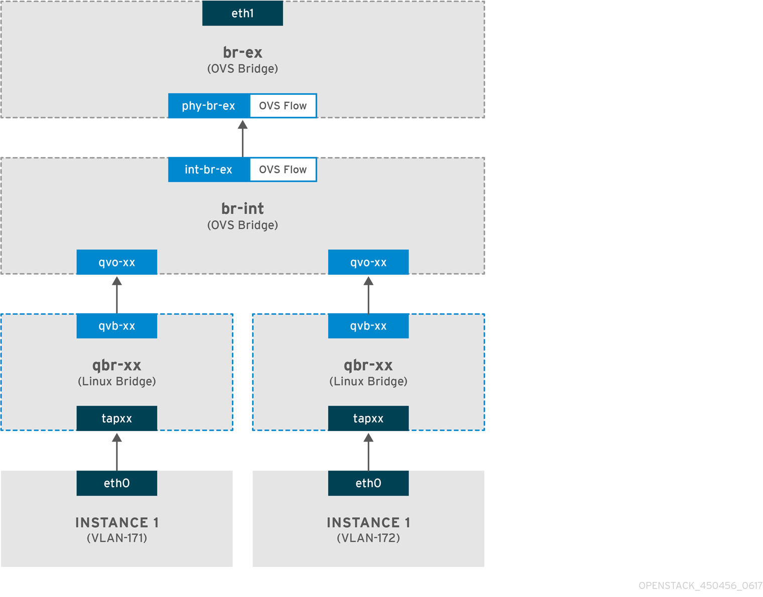
- Packets leaving the eth0 interface of the instance arrive at the linux bridge qbr-xx connected to the instance.
- qbr-xx is connected to br-int using veth pair qvbxx <→ qvoxxx.
- qvbxx is connected to the linux bridge qbr-xx and qvoxx is connected to the Open vSwitch bridge br-int.
Example configuration of qbr-xx on the Linux bridge.
This example features two instances and two corresponding linux bridges:
# brctl show
bridge name	bridge id		STP enabled	interfaces
qbr84878b78-63		8000.e6b3df9451e0	no		qvb84878b78-63
							tap84878b78-63

qbr86257b61-5d		8000.3a3c888eeae6	no		qvb86257b61-5d
							tap86257b61-5d
The configuration of qvoxx on br-int:
                options: {peer=phy-br-ex}
        Port "qvo86257b61-5d"
            tag: 3

            Interface "qvo86257b61-5d"
        Port "qvo84878b78-63"
            tag: 2
            Interface "qvo84878b78-63"
-
qvoxxis tagged with the internal VLAN tag associated with the VLAN provider network. In this example, the internal VLAN tag 2 is associated with the VLAN provider networkprovider-171and VLAN tag 3 is associated with VLAN provider networkprovider-172. When the packet reaches qvoxx, the this VLAN tag is added to the packet header. -
The packet is then moved to the br-ex OVS bridge using patch-peer
int-br-ex<→phy-br-ex. Example patch-peer on br-int:
    Bridge br-int
        fail_mode: secure
       Port int-br-ex
            Interface int-br-ex
                type: patch
                options: {peer=phy-br-ex}
Example configuration of the patch peer on br-ex:
    Bridge br-ex
        Port phy-br-ex
            Interface phy-br-ex
                type: patch
                options: {peer=int-br-ex}
        Port br-ex
            Interface br-ex
type: internal- When this packet reaches phy-br-ex on br-ex, an OVS flow inside br-ex replaces the internal VLAN tag with the actual VLAN tag associated with the VLAN provider network.
The output of the following command shows that the port number of phy-br-ex is 4:
# ovs-ofctl show br-ex
 4(phy-br-ex): addr:32:e7:a1:6b:90:3e
     config:     0
     state:      0
     speed: 0 Mbps now, 0 Mbps max
The following command shows any packet that arrives on phy-br-ex (in_port=4) which has VLAN tag 2 (dl_vlan=2). Open vSwitch replaces the VLAN tag with 171 (actions=mod_vlan_vid:171,NORMAL) and forwards the packet to the physical interface. The command also shows any packet that arrives on phy-br-ex (in_port=4) which has VLAN tag 3 (dl_vlan=3). Open vSwitch replaces the VLAN tag with 172 (actions=mod_vlan_vid:172,NORMAL) and forwards the packet to the physical interface. The neutron-openvswitch-agent adds these rules.
# ovs-ofctl dump-flows br-ex
NXST_FLOW reply (xid=0x4):
NXST_FLOW reply (xid=0x4):
 cookie=0x0, duration=6527.527s, table=0, n_packets=29211, n_bytes=2725576, idle_age=0, priority=1 actions=NORMAL
 cookie=0x0, duration=2939.172s, table=0, n_packets=117, n_bytes=8296, idle_age=58, priority=4,in_port=4,dl_vlan=3 actions=mod_vlan_vid:172,NORMAL
 cookie=0x0, duration=6111.389s, table=0, n_packets=145, n_bytes=9368, idle_age=98, priority=4,in_port=4,dl_vlan=2 actions=mod_vlan_vid:171,NORMAL
 cookie=0x0, duration=6526.675s, table=0, n_packets=82, n_bytes=6700, idle_age=2462, priority=2,in_port=4 actions=drop
- This packet is then forwarded to physical interface eth1.
The flow of incoming traffic in a VLAN provider network
The following example flow was tested on a Compute node using VLAN tag 2 for provider network provider-171 and VLAN tag 3 for provider network provider-172. The flow uses port 18 on the integration bridge br-int.
Your VLAN provider network may require a different configuration. Also, the configuration requirement for a network may differ between two different Compute nodes.
The output of the following command shows int-br-ex with port number 18:
# ovs-ofctl show br-int
 18(int-br-ex): addr:fe:b7:cb:03:c5:c1
     config:     0
     state:      0
     speed: 0 Mbps now, 0 Mbps max
The output of the following command shows the flow rules on br-int.
# ovs-ofctl dump-flows br-int
NXST_FLOW reply (xid=0x4):
 cookie=0x0, duration=6770.572s, table=0, n_packets=1239, n_bytes=127795, idle_age=106, priority=1 actions=NORMAL

 cookie=0x0, duration=3181.679s, table=0, n_packets=2605, n_bytes=246456, idle_age=0,
 priority=3,in_port=18,dl_vlan=172 actions=mod_vlan_vid:3,NORMAL

 cookie=0x0, duration=6353.898s, table=0, n_packets=5077, n_bytes=482582, idle_age=0,
 priority=3,in_port=18,dl_vlan=171 actions=mod_vlan_vid:2,NORMAL

 cookie=0x0, duration=6769.391s, table=0, n_packets=22301, n_bytes=2013101, idle_age=0, priority=2,in_port=18 actions=drop

 cookie=0x0, duration=6770.463s, table=23, n_packets=0, n_bytes=0, idle_age=6770, priority=0 actions=drop
Incoming flow example
This example demonstrates the the following br-int OVS flow:
cookie=0x0, duration=3181.679s, table=0, n_packets=2605, n_bytes=246456, idle_age=0,
priority=3,in_port=18,dl_vlan=172 actions=mod_vlan_vid:3,NORMAL
- A packet with VLAN tag 172 from the external network reaches the br-ex bridge via eth1 on the physical node.
-
The packet moves to br-int via the patch-peer
phy-br-ex <-> int-br-ex. -
The packet matches the flow’s criteria (
in_port=18,dl_vlan=172). -
The flow actions (
actions=mod_vlan_vid:3,NORMAL) replace the VLAN tag 172 with internal VLAN tag 3 and forwards the packet to the instance with normal Layer 2 processing.
Additional resources
7.8. Troubleshooting instance-physical network connections on VLAN provider networks
Refer to the packet flow described in "How does the VLAN provider network packet flow work?" when troubleshooting connectivity in a VLAN provider network. In addition, review the following configuration options:
Procedure
1. Verify that physical network name is used consistently. In this example, physnet1 is used consistently while creating the network, and within the bridge_mapping configuration:
# grep bridge_mapping /etc/neutron/plugins/ml2/openvswitch_agent.ini
bridge_mappings = physnet1:br-ex

# openstack network show provider-vlan171
...
| provider:physical_network | physnet1
...
2. Confirm that the network was created as external, is type vlan, and uses the correct segmentation_id value:
# openstack network show provider-vlan171
...
| provider:network_type     | vlan                                 |
| provider:physical_network | physnet1                             |
| provider:segmentation_id  | 171                                  |
...
3. Run ovs-vsctl show and verify that br-int and br-ex are connected using the patch-peer int-br-ex <→ phy-br-ex.
This connection is created while restarting neutron-openvswitch-agent, provided that the bridge_mapping is correctly configured in /etc/neutron/plugins/ml2/openvswitch_agent.ini.
Recheck the bridge_mapping setting if this is not created even after restarting the service.
4. To review the flow of outgoing packets, run ovs-ofctl dump-flows br-ex and ovs-ofctl dump-flows br-int, and verify that the flows map the internal VLAN IDs to the external VLAN ID (segmentation_id). For incoming packets, map the external VLAN ID to the internal VLAN ID.
This flow is added by the neutron OVS agent when you spawn an instance to this network for the first time. If this flow is not created after spawning the instance, ensure that the network is created as vlan, is external, and that the physical_network name is correct. In addition, re-check the bridge_mapping settings.
5. Finally, re-check the ifcfg-br-ex and ifcfg-ethx configuration. Ensure that br-ex includes port ethX, and that both ifcfg-br-ex and ifcfg-ethx have an UP flag in the output of the ip a command.
For example, the following output shows that eth1 is a port in br-ex:
    Bridge br-ex
        Port phy-br-ex
            Interface phy-br-ex
                type: patch
                options: {peer=int-br-ex}
        Port "eth1"
            Interface "eth1"
The following command shows that eth1 has been added as a port, and that the kernel is configured to move all packets from the interface to the OVS bridge br-ex. This is demonstrated by the entry: master ovs-system.
# ip a
5: eth1: <BROADCAST,MULTICAST,UP,LOWER_UP> mtu 1500 qdisc mq master ovs-system state UP qlen 1000
Additional resources
7.9. Enabling multicast snooping for provider networks in an ML2/OVS deployment
To prevent flooding multicast packets to every port in a Red Hat OpenStack Platform (RHOSP) provider network, you must enable multicast snooping. In RHOSP deployments that use the Modular Layer 2 plug-in with the Open vSwitch mechanism driver (ML2/OVS), you do this by adding the appropriate Puppet variable to a custom environment file and running the openstack overcloud deploy command.
You should thoroughly test and understand any multicast snooping configuration before applying it to a production environment. Misconfiguration can break multicasting or cause erratic network behavior.
Prerequisites
- Your configuration must only use ML2/OVS provider networks.
Your physical routers must also have IGMP snooping enabled.
That is, the physical router must send IGMP query packets on the provider network to solicit regular IGMP reports from multicast group members to maintain the snooping cache in OVS (and for physical networking).
An RHOSP Networking service security group rule must be in place to allow inbound IGMP to the VM instances (or port security disabled).
In this example, a rule is created for the
ping_sshsecurity group:Example
$ openstack security group rule create --protocol igmp --ingress ping_ssh
Procedure
On the undercloud host, logged in as the stack user, create a custom YAML environment file.
Example
$ vi /home/stack/templates/my-ovs-environment.yaml
TipThe Orchestration service (heat) uses a set of plans called templates to install and configure your environment. You can customize aspects of the overcloud with a custom environment file, which is a special type of template that provides customization for your heat templates.
In the YAML environment file under the
ExtraConfigsection for the appropriate role, set the Puppet variable,igmp_snooping_enable, totrue.Example
If the role used is
ComputeOvsDpdk, then the lines that you add to the custom envirnoment file would be:parameter_defaults: ComputeOvsDpdkExtraConfig: neutron::agents::ml2::ovs::igmp_snooping_enable: trueImportantEnsure that you add a whitespace character between the single colon (:) and the value.
Run the
openstack overcloud deploycommand and include the core heat templates, environment files, and this new custom environment file.ImportantThe order of the environment files is important as the parameters and resources defined in subsequent environment files take precedence.
Example
$ openstack overcloud deploy --templates \
-e [your-environment-files] \
-e /usr/share/openstack-tripleo-heat-templates/environments/services/my-ovs-environment.yaml
Verification steps
Verify that the multicast snooping is enabled.
Example
# sudo ovs-vsctl list bridge br-int
Sample output
...
mcast_snooping_enable: true
...
other_config: {mac-table-size="50000", mcast-snooping-disable-flood-unregistered=True}
...
Additional resources
- Neutron in Component, Plug-In, and Driver Support in Red Hat OpenStack Platform
- Environment Files in the Advanced Overcloud Customization guide
- Including Environment Files in Overcloud Creation in the Advanced Overcloud Customization guide
7.10. Enabling multicast in an ML2/OVN deployment
To support multicast traffic, modify the deployment’s security configuration to allow multicast traffic to reach the virtual machine (VM) instances in the multicast group. To prevent multicast traffic flooding, enable IGMP snooping.
Test and understand any multicast snooping configuration before applying it to a production environment. Misconfiguration can break multicasting or cause erratic network behavior.
Prerequisites
- An OpenStack deployment with the ML2/OVN mechanism driver.
Procedure
Configure security to allow multicast traffic to the appropriate VM instances. For instance, create a pair of security group rules to allow IGMP traffic from the IGMP querier to enter and exit the VM instances, and a third rule to allow multicast traffic.
Example
A security group mySG allows IGMP traffic to enter and exit the VM instances.
 openstack security group rule create --protocol igmp --ingress mySG

 openstack security group rule create --protocol igmp --egress mySG
Another rule allows multicast traffic to reach VM instances.
openstack security group rule create --protocol udp mySG
As an alternative to setting security group rules, some operators choose to selectively disable port security on the network. If you choose to disable port security, consider and plan for any related security risks.
Set the heat parameter
NeutronEnableIgmpSnooping: Truein an environment file on the undercloud node. For instance, add the following lines to ovn-extras.yaml.Example
parameter_defaults:
        NeutronEnableIgmpSnooping: True
Include the environment file in the
openstack overcloud deploycommand with any other environment files that are relevant to your environment and deploy the overcloud.$ openstack overcloud deploy \ --templates \ … -e <other_overcloud_environment_files> \ -e ovn-extras.yaml \ …
Replace
<other_overcloud_environment_files>with the list of environment files that are part of your existing deployment.
Verification steps
Verify that the multicast snooping is enabled. List the northbound database Logical_Switch table.
$ ovn-nbctl list Logical_Switch
Sample output
_uuid         : d6a2fbcd-aaa4-4b9e-8274-184238d66a15
other_config  : {mcast_flood_unregistered="false", mcast_snoop="true"}
...
The Networking Service (neutron) igmp_snooping_enable configuration is translated into the mcast_snoop option set in the other_config column of the Logical_Switch table in the OVN Northbound Database. Note that mcast_flood_unregistered is always “false”.
Show the IGMP groups.
$ ovn-sbctl list IGMP_group
Sample output
_uuid    : 2d6cae4c-bd82-4b31-9c63-2d17cbeadc4e
address  : "225.0.0.120"
chassis  : 34e25681-f73f-43ac-a3a4-7da2a710ecd3
datapath : eaf0f5cc-a2c8-4c30-8def-2bc1ec9dcabc
ports    : [5eaf9dd5-eae5-4749-ac60-4c1451901c56, 8a69efc5-38c5-48fb-bbab-30f2bf9b8d45]
...
Additional resources
- Neutron in Component, Plug-In, and Driver Support in Red Hat OpenStack Platform
- Environment Files in the Advanced Overcloud Customization guide
- Including Environment Files in Overcloud Creation in the Advanced Overcloud Customization guide
7.11. Enabling Compute metadata access
Instances connected as described in this chapter are directly attached to the provider external networks, and have external routers configured as their default gateway. No OpenStack Networking (neutron) routers are used. This means that neutron routers cannot be used to proxy metadata requests from instances to the nova-metadata server, which may result in failures while running cloud-init. However, this issue can be resolved by configuring the dhcp agent to proxy metadata requests. You can enable this functionality in /etc/neutron/dhcp_agent.ini. For example:
enable_isolated_metadata = True
7.12. Floating IP addresses
You can use the same network to allocate floating IP addresses to instances, even if the floating IPs are already associated with private networks. The addresses that you allocate as floating IPs from this network are bound to the qrouter-xxx namespace on the Network node, and perform DNAT-SNAT to the associated private IP address. In contrast, the IP addresses that you allocate for direct external network access are bound directly inside the instance, and allow the instance to communicate directly with external network.