
Red Hat Training
A Red Hat training course is available for Red Hat Fuse
Chapter 2. Editing a routing context in the route editor
The following sections describe how to edit a routing context.
2.1. Adding patterns to a route
Routes consist of a sequence of connected patterns, referred to as nodes once they are placed on the canvas inside a Route container node. A complete route typically consists of a starting endpoint, a string of processing nodes, and one or more destination endpoints.
When you add a pattern into a Route container on the canvas, the pattern takes on a color that indicates its type of node:
-
Blue — Route containers, which correspond to route elements in the context file, and other container nodes, such as
whenandotherwiseEIPs that contain other EIPs that complete their logic - Green — Consumer endpoints that input data entering routes
- Orange — EIPs that route, transform, process, or control the flow of data transiting routes
- Purple — Producer endpoints that output the data exiting routes
Procedure
To add a pattern to a route:
- In the Palette, locate the pattern that you want to add to the route.
Use one of the following methods:
- Click the pattern in the Palette and then, in the canvas, click the route container.
Drag the pattern over the target
Routecontainer and drop it.Alternatively, you can add a pattern on an existing node that has no outgoing connection, or on a connection existing between two nodes, to have the tooling automatically wire the connections between all nodes involved.
The tooling checks whether the resulting connection is valid and then either allows or prevents you from adding the pattern on the target. For valid connections, the tooling behaves differently depending on whether the target is a node or a connection:
- For an existing node, the tooling adds the new node to the target node’s outgoing side (beneath or to the right of it depending on how the editor preferences are set) and automatically wires the connection between them
- For an existing connection, the tooling inserts the new node between the two connected nodes and automatically rewires the connections between the three nodes
Optionally, you can manually connect two nodes:
-
In the
Routecontainer on the canvas, select the source node to display its connector arrow. Drag the source node’s connector arrow (
 ) to the target node, and release the mouse button to drop the connector on it.
Note
) to the target node, and release the mouse button to drop the connector on it.
NoteNot all nodes can be connected. When you try to connect a source node to an invalid target node, the tooling displays the
 symbol attached to the mouse cursor, and the connector fails to stick to the target node.
-
In the
After you add a pattern inside a Route container, you can drag it to different location inside the route container or to another route container on the canvas, as long as it can establish a valid connection. You can also relocate existing nodes that are already connected, as long as the move can establish another valid connection.
To view a short video that illustrates how to reposition endpoints, click here.
- Select File → Save. The tooling saves routes in the context file regardless of whether they are complete.
The new pattern appears on the canvas in the Route container and becomes the selected node. The Properties view displays a list of the new node’s properties that you can edit.
Changing the layout direction
When you connect one node to another, the tooling updates the layout according to the route editor’s layout preference. The default is Down.
To access the route editor 's layout preference:
- On Linux and Windows machines, select Windows → Preferences → Fuse Tooling → Editor → Choose the layout direction for the diagram editor.
- On OS X, select Developer Studio → Preferences → Fuse Tooling → Editor → Choose the layout direction for the diagram editor.
2.2. Configuring a pattern
Overview
Most patterns require some explicit configuration. For example, an endpoint requires an explicitly entered URI.
The tooling’s Properties view provides a form that lists all of the configuration details a particular pattern supports. The Properties view also provides the following convenience features:
- validating that all required properties have values
- validating that supplied values are the correct data type for the property
- drop-down lists for properties that have a fixed set of values
- drop-down lists that are populated with the available bean references from the Apache Camel Spring configuration
Procedure
To configure a pattern:
On the canvas, select the node you want to configure.
The Properties view lists all of the selected node’s properties for you to edit. For EIPs, the Details tab lists all of a pattern’s properties. For components from the Components drawer, the Details tab lists the general properties and those that require a value, and the Advanced tab lists additional properties grouped according to function.
The Documentation tab describes the pattern and each of its properties.
- Edit the fields in the Properties view to configure the node.
- When done, save your work by selecting File → Save from the menu bar.
2.3. Removing patterns from a route
Overview
As you develop and update a route, you may need to remove one or more of the route’s nodes. The node’s
 icon makes this easy to do. When you delete a node from the canvas, all of its connections with other nodes in the route are also deleted, and the node is removed from the corresponding route element in the context file.
You can also remove a node by opening its context menu and selecting Remove.
Procedure
To remove a node from a route:
- Select the node you want to delete.
-
Click its
icon.
- Click Yes when asked if you are sure you want to delete this element.
The node and all of its connections are deleted from the canvas, and the node is removed from its corresponding route element in the context file.
2.4. Adding routes to the routing context
Overview
The camelContext element within an XML context file creates a routing context. The camelContext element can contain one or more routes, and each route, displayed on the canvas as a Route container node, maps to a route element in the generated camelContext element.
Procedure
To add another route to the camelContext:
In the Design tab, do one of the following:
-
Click a
Routepattern in the Palette's Routing drawer and then click in the canvas where you want to place the route. Drag a
Routepattern from the Palette's Routing drawer and drop it onto the canvas.The Properties view displays a list of the new route’s properties that you can edit.
-
Click a
In the Properties view, enter:
An ID (for example, Route2) for the new route in the route’s Id field
NoteThe tooling automatically assigns an ID to EIP and component patterns dropped on the canvas. You can replace these autogenerated IDs with your own to distinguish the routes in your project.
- A description of the route in the Description field
- Values for any other properties, as needed. Required properties are indicated by an asterisk (*).
- On the menu bar, select File → Save to save the changes you made to the routing context file.
To switch between multiple routes, select the route that you want to display on the canvas by clicking its entry under the project’s
Camel Contextsfolder in the Project Explorer view.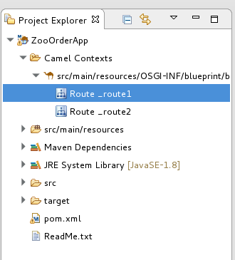
- To display all routes in the context, as space allows, click the context file entry in the Project Explorer view.
To view the code generated by the tooling when you add a route to the canvas, click the Source tab.
NoteYou can alternately add a route in the Source tab, by adding a <route/> element to the existing list within the camelContext element.
2.5. Deleting a route
Overview
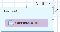
In some cases you made need to delete an entire route from your routing context. The Route container’s
icon makes this easy to do. When you delete a route, all of the nodes inside the Route container are also deleted, and the corresponding route element in the context file is removed.
You can also remove a route using the Route container’s context menu and selecting Remove.
You cannot undo this operation.
Procedure
To delete a route:
If the routing context contains more than one route, first select the route you want to delete in the Project Explorer view.
On the canvas, click the Route container’s
icon.
- Click Yes when asked if you are sure you want to delete this element.
The route is removed from the canvas, from the context file, and from the Project Explorer view.
2.6. Adding global endpoints, data formats, or beans
Overview
Some routes rely on shared configuration provided by global endpoints, global data formats, or global beans. You can add global elements to the project’s routing context file by using the route editor’s Configurations tab.
To add global elements to your routing context file:
- Open your routing context file in the route editor.
At the bottom of the route editor, click the Configurations tab to display global configurations, if there are any.
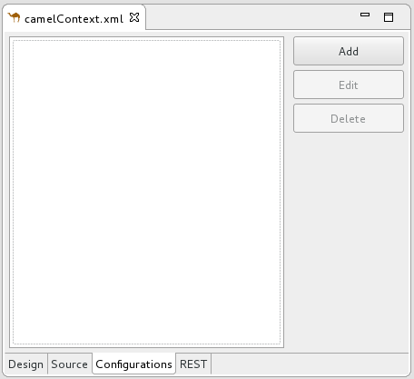
Click Add to open the Create a new global element dialog.
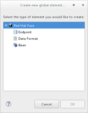
The options are:
- Endpoint — see the section called “Adding a global endpoint”.
- Data Format — see the section called “Adding a global data format”.
- Bean — see the section called “Adding a global bean”.
Adding a global endpoint
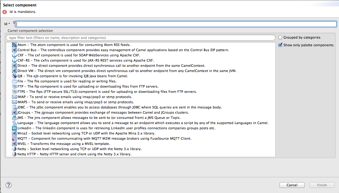
In the Create a new global element dialog, select Endpoint and click OK to open the Select component dialog.
 Note
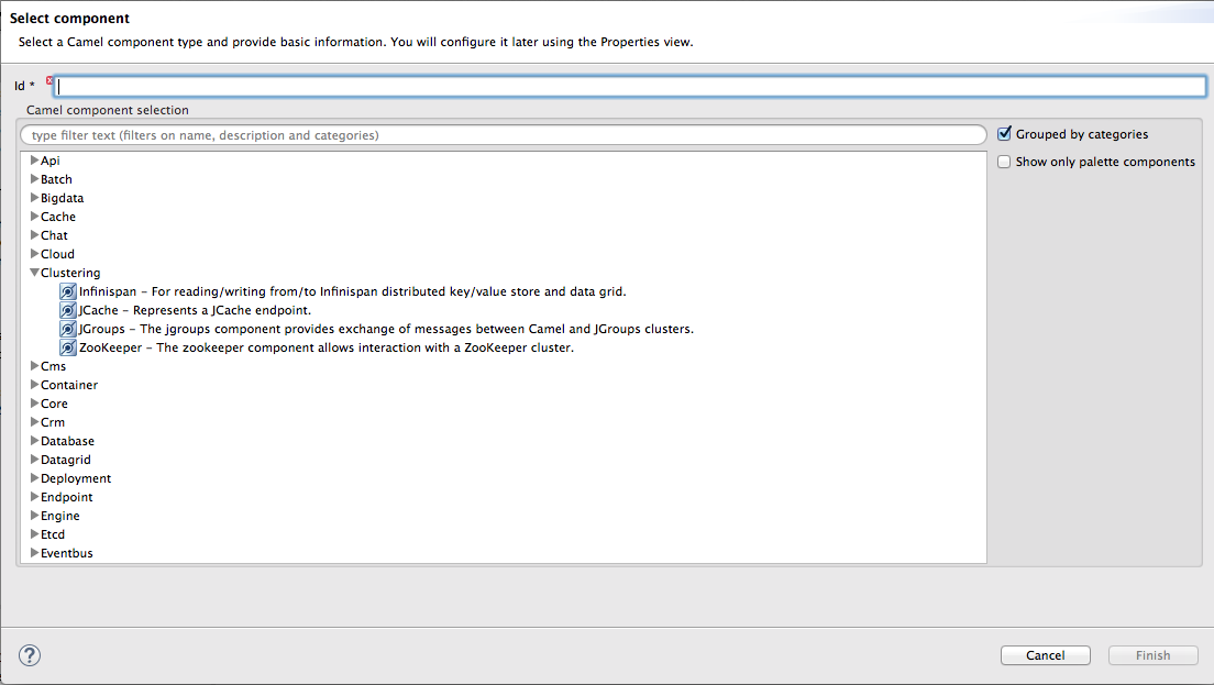
NoteBy default, the Select component dialog opens with the Show only palette components option enabled. To see all available components, uncheck this option.
NoteThe Grouped by categories option groups components by type.
In the Select component dialog, scroll through the list of Camel components to find and select the component you want to add to the context file, and then enter an ID for it in the Id field.
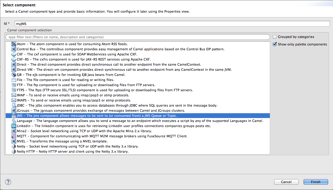
In this example, the JMS component is selected and
myJMSis the Id value.Click Finish.

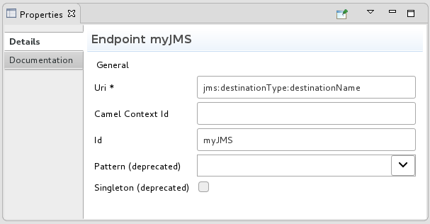
You can now set properties in the Properties view as needed.
The tooling autofills Id with the value you entered in the component’s
Idfield in [globalEndptSelect]. In this example, Camel builds theuri(required field) starting with the component’s schema (in this case,jms:), but you must specify the destinationName and the destinationType to complete the component’s uri.NoteFor the JMS component, the destination type defaults to
queue. This default value does not appear in theurifield on the Details page until you have entered a value in Destination Name (required field).- To complete the component’s uri, click Advanced.
In the Destination Name field, enter the name of the destination endpoint (for example,
FOO.BAR). In the Destination Type field, enter the endpoint destination’s type (for example,queue,topic,temp:queue, ortemp:topic).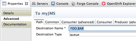
The Properties view’s Details and Advanced tabs provide access to all properties available for configuring a particular component.
Click the Consumer (advanced) tab.
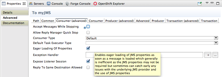
Enable the properties Eager Loading Of Properties and Expose Listener Session.
In the route editor, switch to the Source tab to see the code that the tooling added to the context file (in this example, a configured JMS endpoint), before the first route element.

- When done, save your changes by selecting File → Save on the menu bar.
Adding a global data format
In the Create a new global element dialog, select Data Format and click OK to open the Create a global Data Format dialog.
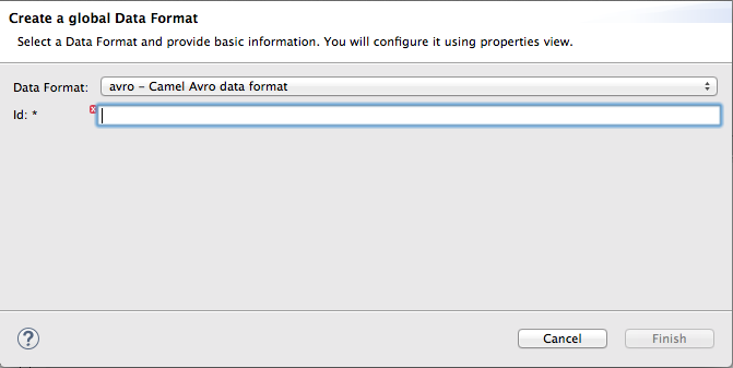
The data format defaults to
avro, the format at the top of the list of those available.-
Open the Data Format drop-down menu, and select the format you want, for example,
xmljson. In the Id field, enter a name for the format, for example, myDataFormat).
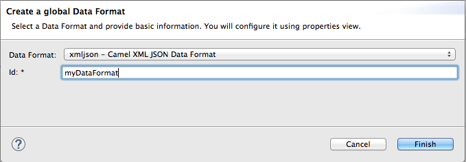
Click Finish.
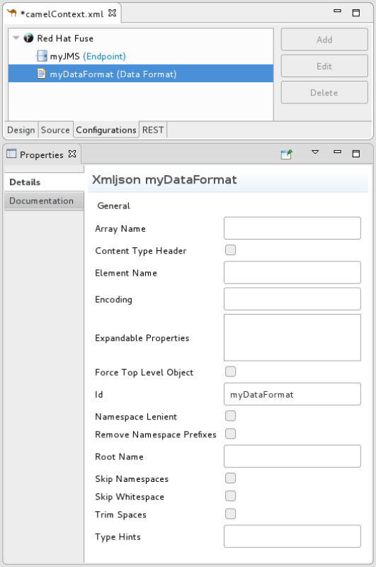
In the Properties view, set property values as appropriate for your project, for example:
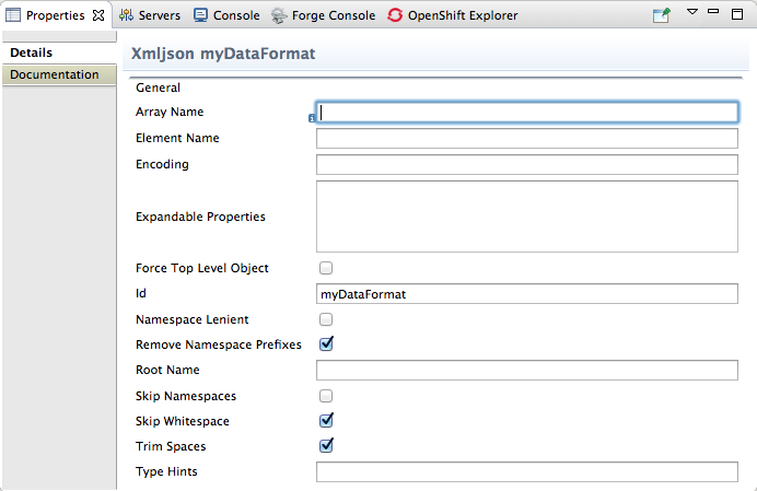
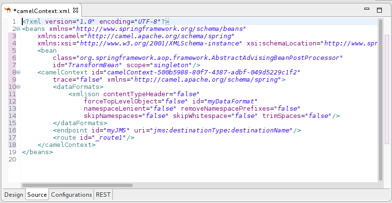
In the route editor, click the Source tab to see the code that the tooling added to the context file. In this example, a configured xmljson data format is before the first route element.
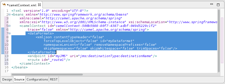
- When done, save your changes by selecting File → Save on the menu bar.
Adding a global bean
A global bean enables out-of-route bean definitions that can be referenced from anywhere in the route. When you copy a Bean component from the palette to the route, you can find defined global beans in the Properties view’s Ref dropdown. Select the global bean that you want the Bean component to reference.
To add a global bean element:
In the Create a new global element window, select Bean and click OK to open the Bean Definition dialog.
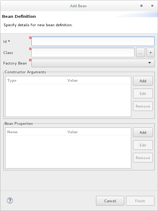
- In the Id field, enter an ID for the global bean, for example, TransformBean. The ID must be unique in the configuration.
Identify a bean class or a factory bean.
To specify a factory bean, you must have already added another global bean with a factory class specified. You can then select that global bean to declare it as a global bean factory. One instance of the bean factory class will be in the runtime. Other global beans can call factory methods on that class to create their own instances of other classes.
To fill the Class field, do one of the following:
- Enter the name of a class that is in the project or in a referenced project.
- Click … to navigate to and select a class that is in the project or in a referenced project.
- Click + to define a new bean class and add it as a global bean.
If the bean you are adding requires one or more arguments, in the Constructor Arguments section, for each argument:
- Click Add.
-
Optionally, in the Type field, enter the type of the argument. The default is
java.lang.String. - In the Value field, enter the value of the argument.
- Click OK.
Optionally specify one or more properties that are accessible to the global bean. In the Bean Properties section, do the following for each property:
- Click Add.
- In the Name field, enter the name of the property.
- In the Value field, enter the value of the property.
- Click OK.
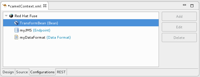
Click Finish to add the global bean to the configuration. The global bean ID you specified appears in the Configurations tab, for example:
Switch to the Source tab to see the
beanelement that the tooling added to the context file. For example: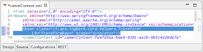
Click the Configurations tab to return to the list of global elements and select a global bean to display its standard properties in the Properties view, for example:
 Note
NoteTo view or edit a property that you specified when you added a global bean, select the bean in the Configurations tab and then click Edit.
Set global bean properties as needed:
-
Depends-on is a string that you can use to identify a bean that must be created before this global bean. Specify the ID (name) of the depended on bean. For example, if you are adding the
TransformBeanand you set Depends-on toChangeCaseBeanthenChangeCaseBeanmust be created and thenTransformBeancan be created. When the beans are being destroyed thenTransformBeanis destroyed first. - Factory-method is useful only when the global bean is a factory class. In this situation, specify or select a static factory method to be called when the bean is referenced.
-
Scope is
singletonorprototype. The default,singleton, indicates that Camel uses the same instance of the bean each time the bean is called. Specifyprototypewhen you want Camel to create a new instance of the bean each time the bean is called. -
Init-method lets you specify or select which of the bean’s
init()methods to call when the bean is referenced. - Destroy-method lets you specify or select which of the bean’s destory methods to call when the processing performed by the bean is done.
-
Depends-on is a string that you can use to identify a bean that must be created before this global bean. Specify the ID (name) of the depended on bean. For example, if you are adding the
- When done, save your changes by selecting File → Save on the menu bar.
Deleting a global element
The procedure is the same whether removing an endpoint, data format or bean that was previously added to the routing context.
You cannot perform an undo operation for deletion of a global element. If you inadvertently delete a global element that you want to keep in the configuration you might be able to undo the deletion by closing the context file without saving it. If this is not feasible then re-add the inadvertently deleted global element.
In the Configurations tab, select the global element that you want to delete.
For example, suppose you want to delete the data format
myDataFormatthat was added in the section called “Adding a global data format”:
Click Delete.
The global element
myDataFormatdisappears from the Configurations tab.Switch to the Source tab to check that the tooling removed the XML code from the routing context.
- When done, save your changes by selecting File → Save on the menu bar.
Editing a global element
The procedure is the same whether modifying the properties of an endpoint, data format or bean that you added to the routing context.
Typically, you do not want to change the ID of a global element. If the global element is already in use in a running route, changing the ID can break references to the global element.
In the Configurations tab, select the global element that you want to edit.
For example, to edit the endpoint
myJMSthat was added in the section called “Adding a global endpoint”, select it: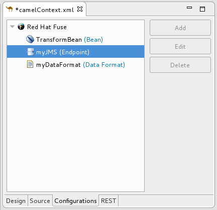
Click Edit.
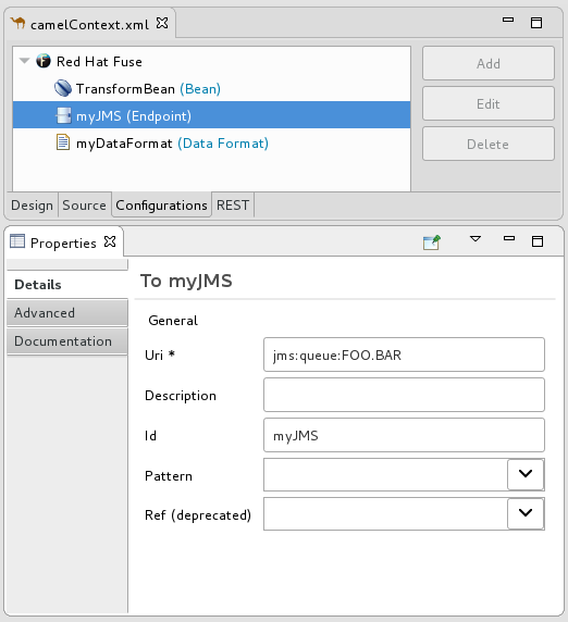
In the Properties view, modify the element’s properties as needed.
For example, open the Advanced → Consumer tab, and change the value of Concurrent Consumers to
2: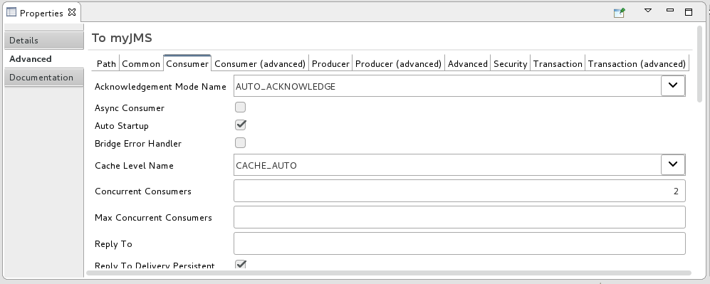
In the route editor, click the Source tab and check that the tooling added the property
concurrentConsumers=2to the routing context: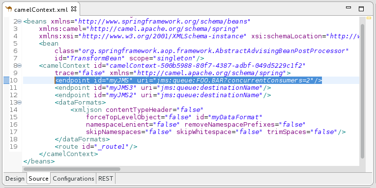
- When done, save your changes by selecting File → Save on the menu bar.
2.7. Configuring the route editor
Overview
Using Fuse preference settings, you can specify options for the route editor’s behavior and user interface:
- The default language to use for expressions in Enterprise Integration Patterns (EIPs)
- The direction (to the right or down) in which patterns flow on the Design canvas when you create routes
- Whether the Design canvas displays a grid overlay in the background of the canvas.
- The method for labeling nodes on the Design canvas
Procedure
To configure the route editor:
Open the Editor preferences window:
- On Linux and Windows machines, select Windows → Preferences → Fuse Tooling → Editor.
On OS X, select Developer Studio → Preferences → Fuse Tooling → Editor.
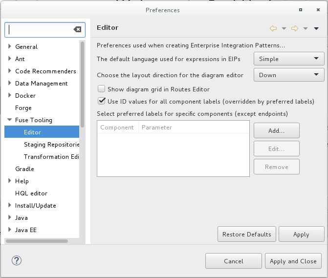
- To select the default language that you want to use for expressions in Enterprise Integration Pattern (EIP) components, select a language from the drop-down list. The default is Simple.
- To specify the direction in which you want the route editor to align the patterns in a route, select Down or Right. The default is Down.
- To enable or disable displaying a grid overlay on the background of the canvas, check the box next to Show diagram grid in Routes Editor. The default is enabled.
To enable or disable using component IDs as labels in the route editor’s Design tab, check the box next to Use ID values for component labels. The default is disabled.
If you check this option and also specify a preferred label for a component (see Step 6), then the preferred label is used for that component instead of the ID value.
To use a parameter as the label for a component (except for endpoints, such as File nodes) in the route editor’s Design tab:
In the Preferred labels section, click Add. The New Preferred Label dialog opens.
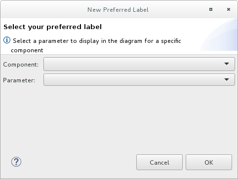
- Select a Component and then select the Parameter to use as the label for the component.
Click OK. The component and parameter pairs are listed in the Editor Preferences window.
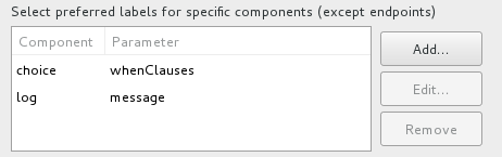
You can optionally Edit and Remove component labels.
NoteIf you check the Use ID values for component labels option, it applies to all components except for the components listed in the Preferred labels section.
- Click Apply and Close to apply the changes to the Editor preferences and close the Preferences window.
You can restore the route editor’s original defaults at any time by returning to the Editor preferences dialog and clicking Restore Defaults.