
Red Hat Training
A Red Hat training course is available for Red Hat Enterprise Linux
7.3. Backup Fencing Configuration Procedure
This section provides the procedure for adding two APC fence devices to each node of cluster
backupclust, configured as a single main fence method to ensure that the fencing is successful. This procedure also configures an IPMI management board as a backup fence device for each node of cluster backupclust.
This example uses the same APC switches for each cluster node. The APC switches will first be configured as shared fence devices. After configuring the APC switches as shared fence devices, the APC devices and the IPMI devices will be added as fence devices for each node in the cluster.
7.3.1. Configuring the APC switches as shared fence devices
To configure the first APC switch as a shared fence device named
pwr01 using Conga, perform the following procedure:
- As an administrator of luci Select the cluster tab. This displays the Choose a cluster to administer screen.
- From the Choose a cluster to administer screen, you should see the previously configured cluster
backupclustdisplayed, along with the nodes that make up the cluster. Click onbackupclustto select the cluster. - At the detailed menu for the cluster
backupclust(below the menu on the left side of the screen), click . Clicking causes the display of any shared fence devices previously configured for a cluster and causes the display of menu items for fence device configuration: and . - Click . Clicking causes the Add a Sharable Fence Device page to be displayed.
- At the Add a Sharable Fence Device page, click the drop-down box under and select . This causes Conga to display the components of an APC Power Switch fencing type, as shown in Figure 3.2, “Adding a Sharable Fence Device”.
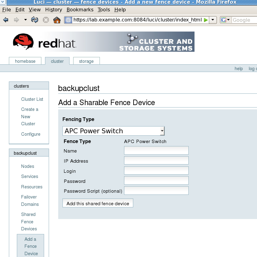
Figure 7.2. Adding a Sharable Fence Device
- For , enter
pwr01. - For , enter
10.15.86.96. - For , enter
apclogin. - For , enter
apcpword. - For , leave blank.
- Click .Clicking temporarily displays a a progress page. After the fence device has been added, the detailed cluster properties menu is updated with the fence device under .
To configure the second APC switch as a shared fence device named
pwr02, perform the following procedure:
- After configuring the first APC switch as shared fence device
pwr01, click from the detailed menu for the clusterbackupclust(below the menu on the left side of the screen). This displays the Add a Sharable Fence Device page. - At the Add a Sharable Fence Device page, click the drop-down box under and select . This causes Conga to display the components of an APC Power Switch fencing type.
- For , enter
pwr02. - For , enter
10.15.86.97. - For , enter
apclogin. - For , enter
apcpword. - For , leave blank.
- Click .Clicking causes a progress page to be displayed temporarily. After the fence device has been added, the detailed cluster properties menu is updated with the fence device under .
7.3.2. Configuring Fencing on the First Cluster Node
After configuring the APC switches as shared fence devices, use the following procedure to configure the first APC switch,
pwr01, as the first fence device for node clusternode1.example.com.
- At the detailed menu for the cluster
backupclust(below the menu), click . Clicking causes the display of the status of each node inbackupclust. - At the bottom of the display for node
clusternode1.example.com, click . This displays the configuration screen for nodeclusternode1.example.com. - At the
Main Fencing Methoddisplay, click . This causes a dropdown menu to display. - From the dropdown menu, the and fence devices you have already created should display as one of the menu options under . Select . This causes a fence device configuration menu to display with the , , ,, and values already configured, as defined when you configured
pwr01as a shared fence device. (The value does not display, but you may not alter it.) This is shown in Figure 7.3, “Adding Fence Device pwr01 to a Node”.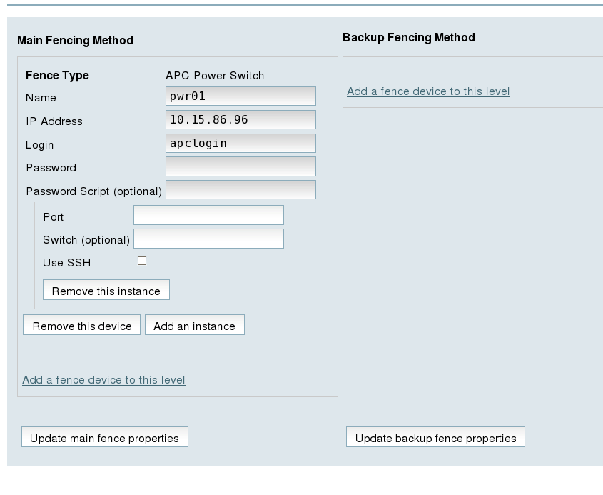
Figure 7.3. Adding Fence Device pwr01 to a Node
- For , enter
1. Do not enter any value for .
Before updating the main fence properties for this node, use the following procedure to add
pwr02 as the second fence device of the main fencing method for node clusternode1.example.com.
- Beneath the configuration information for
pwr01that you have entered, click . This displays the dropdown menu again. - From the dropdown menu, select . This causes a fence device configuration menu to display with the , , ,, and values already configured, as defined when you configured
pwr02as a shared fence device. This is shown in Figure 7.4, “Adding Fence Device pwr02 to a Node”.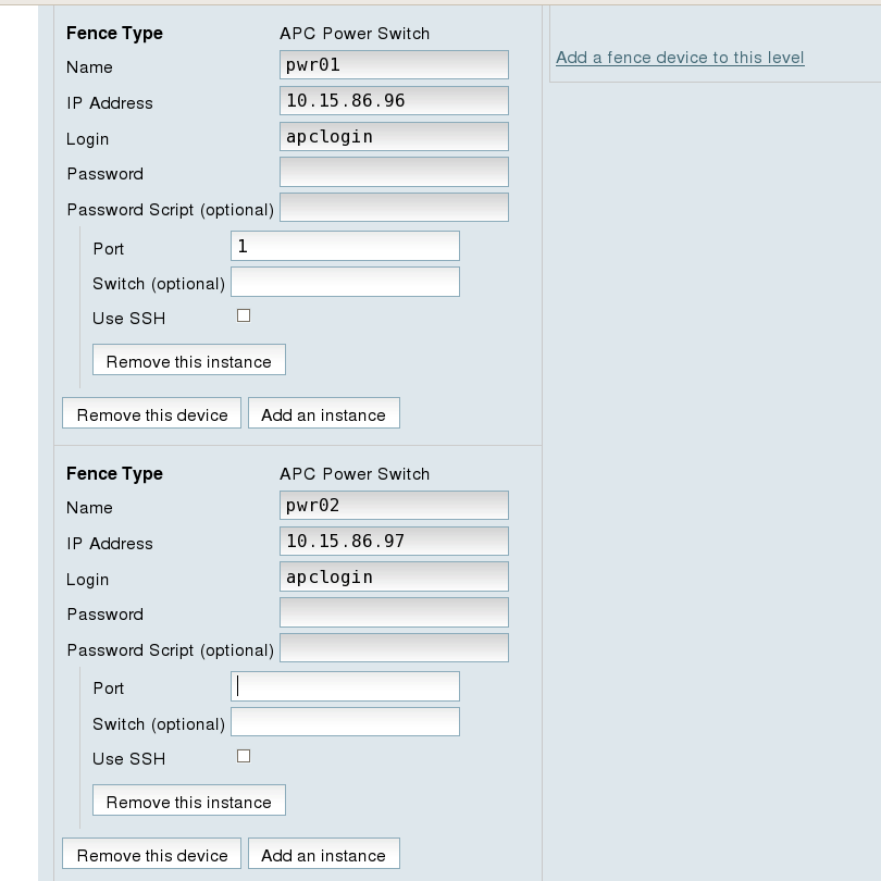
Figure 7.4. Adding Fence Device pwr02 to a Node
- For , enter
1. Do not enter any value for .
After entering the configuration information for both power sources to use as fence devices, you can update the main fence properties using the following procedure.
- Click . This causes a confirmation screen to be displayed.
- On the confirmation screen, Click . A progress page is displayed after which the display returns to the status page for
clusternode2.example.comin clusterbackupclust.
After configuring the main fence method for
clusternode1.example.com and updating the main fence properties, use the following procedure to configure the IPMI management board for node clusternode1.example.com as the backup fencing method for that node:
- At the
Backup Fencing Methoddisplay, click . This causes a dropdown manu to display. - From the dropdown menu, under , select . This displays a fence device configuration menu, as shown in Figure 7.5, “Configuring a Backup Fencing Method”.
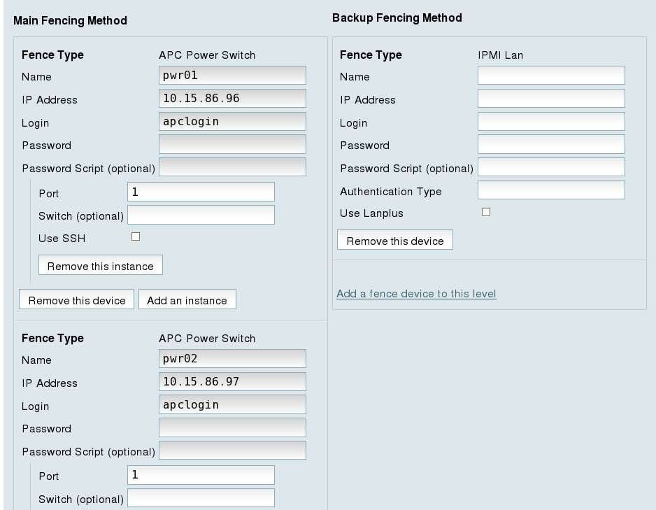
Figure 7.5. Configuring a Backup Fencing Method
- For , enter
ipmifence1. - For , enter
10.15.86.50. - For , enter
ipmilogin. - For , enter
ipmipword. - For , leave the field blank.
- For , enter
password. This field specifies the IPMI authentication type. Possible values for this field are none,password,md2, ormd5. - Leave the field blank. You would check this field if your fence device is a Lanplus-capable interface such as iLO2.
After entering the configuration information for the backup fencing method for
clusternode1.example.com, you can update the backup fence properties using the following procedure.
- Click at the bottom of the right side of the screen. This causes a confirmation screen to be displayed.
- On the confirmation screen, click . After the fence device has been added, a progress page is displayed after which the display returns to the configuration page for
clusternode1.example.comin clusterbackupclust.
7.3.3. Configuring Fencing on the Remaining Cluster Nodes
After configuring the main fencing method and the backup fencing method for
clusternode1.example.com, use the same procedure to configure the fencing methods for clusternode2.example.com and clusternode3.example.com.
- At the detailed menu for the cluster
backupclust(below the menu on the left side of the screen) click on , which should be displayed below -> . This displays the configuration screen for nodeclusternode2.example.com. - At the
Main Fencing Methoddisplay, click . This causes a dropdown menu to display. - From the dropdown menu, the and fence devices you have already created should display as one of the menu options under . Select . This causes a fence device configuration menu to display with the , , ,, and values already configured, as defined when you configured
pwr01as a shared fence device. (The value does not display, but you may not alter it.) - For , enter
2. Do not enter any value for .
Before updating the main fence properties for this node, use the following procedure to add
pwr02 as the second fence device of the main fencing method for node clusternode1.example.com.
- Beneath the configuration information for
pwr01that you have entered, click . This displays the dropdown menu again. - From the dropdown menu, select . This causes a fence device configuration menu to display with the , , ,, and values already configured, as defined when you configured
pwr02as a shared fence device. - For , enter
2. Do not enter any value for .
After entering the configuration information for both power sources to use as fence devices, you can update the main fence properties using the following procedure.
- Click . This causes a confirmation screen to be displayed.
- On the confirmation screen, Click . A progress page is displayed after which the display returns to the status page for
clusternode1.example.comin clusterbackupclust.
After configuring the main fence method for
clusternode2.example.com and updating the main fence properties, use the following procedure to configure the IPMI management board for node clusternode2.example.com as the backup fencing method for that node:
- At the
Backup Fencing Methoddisplay, click . This causes a dropdown manu to display. - From the dropdown menu, under , select . This displays a fence device configuration menu.
- For , enter
ipmifence1. - For , enter
10.15.86.51. - For , enter
ipmilogin. - For , enter
ipmipword. - For , leave the field blank.
- For , enter
password. This field specifies the IPMI authentication type. Possible values for this field are none,password,md2, ormd5. - Leave the field blank.
After entering the configuration information for the backup fencing method for
clusternode2.example.com, you can update the backup fence properties using the following procedure.
- Click at the bottom of the right side of the screen. After the fence device has been added, a progress page is displayed after which the display returns to the configuration page for
clusternode2.example.comin clusterbackupclust.
To configure the fencing methods for
clusternode3.example.com, use the same procedure as you did for configuring the fencing methods for clusternode2.example.com. In this case, however, use 3 as the port number for both of the APC switches that you are using for the main fencing method. For the backup fencing method, use ipmifence3 as the name of the fence type and use an IP address of 10.15.86.52. The other components should be the same, as summarized in Table 7.7, “Fence Agent Components to Specify for clusternode3.example.com”.