
Red Hat Training
A Red Hat training course is available for Red Hat Enterprise Linux
1.10. Linux Virtual Server Administration GUI
This section provides an overview of the LVS configuration tool available with Red Hat Cluster Suite — the Piranha Configuration Tool. The Piranha Configuration Tool is a Web-browser graphical user interface (GUI) that provides a structured approach to creating the configuration file for LVS —
/etc/sysconfig/ha/lvs.cf.
To access the Piranha Configuration Tool you need the
piranha-gui service running on the active LVS router. You can access the Piranha Configuration Tool locally or remotely with a Web browser. You can access it locally with this URL: http://localhost:3636. You can access it remotely with either the hostname or the real IP address followed by :3636. If you are accessing the Piranha Configuration Tool remotely, you need an ssh connection to the active LVS router as the root user.
Starting the Piranha Configuration Tool causes the Piranha Configuration Tool welcome page to be displayed (refer to Figure 1.26, “The Welcome Panel”). Logging in to the welcome page provides access to the four main screens or panels: CONTROL/MONITORING, GLOBAL SETTINGS, REDUNDANCY, and VIRTUAL SERVERS. In addition, the VIRTUAL SERVERS panel contains four subsections. The CONTROL/MONITORING panel is the first panel displayed after you log in at the welcome screen.
Figure 1.26. The Welcome Panel
The following sections provide a brief description of the Piranha Configuration Tool configuration pages.
1.10.1. CONTROL/MONITORING
The CONTROL/MONITORING Panel displays runtime status. It displays the status of the
pulse daemon, the LVS routing table, and the LVS-spawned nanny processes.
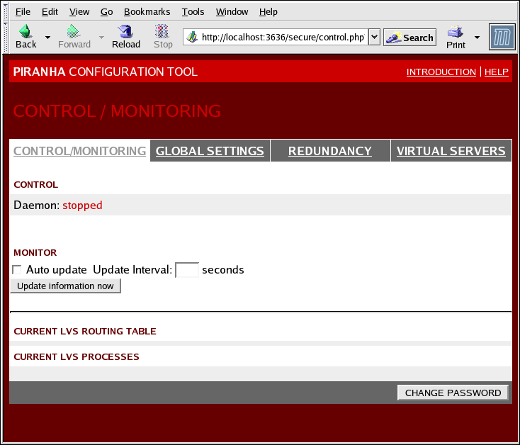
Figure 1.27. The CONTROL/MONITORING Panel
- Auto update
- Enables the status display to be updated automatically at a user-configurable interval set in the Update frequency in seconds text box (the default value is 10 seconds).It is not recommended that you set the automatic update to an interval less than 10 seconds. Doing so may make it difficult to reconfigure the Auto update interval because the page will update too frequently. If you encounter this issue, simply click on another panel and then back on CONTROL/MONITORING.
- Provides manual update of the status information.
- Clicking this button takes you to a help screen with information on how to change the administrative password for the Piranha Configuration Tool.
1.10.2. GLOBAL SETTINGS
The GLOBAL SETTINGS panel is where the LVS administrator defines the networking details for the primary LVS router's public and private network interfaces.
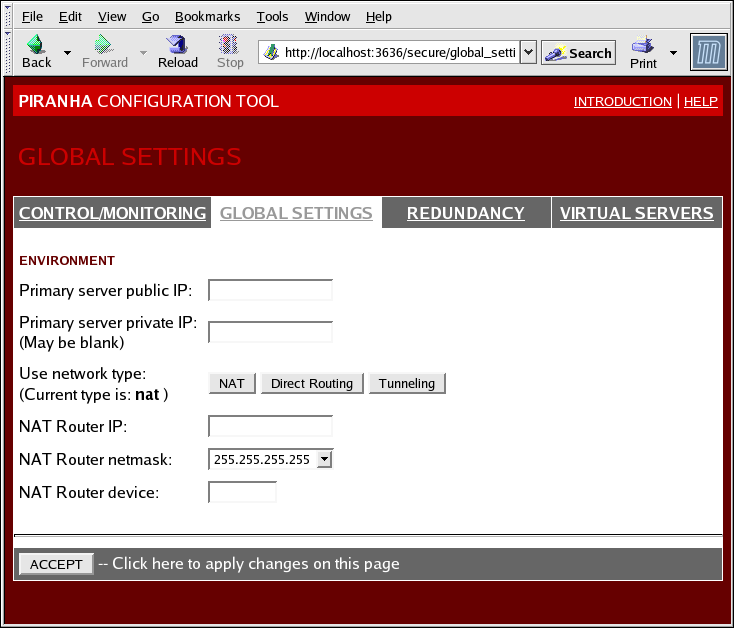
Figure 1.28. The GLOBAL SETTINGS Panel
The top half of this panel sets up the primary LVS router's public and private network interfaces.
- Primary server public IP
- The publicly routable real IP address for the primary LVS node.
- Primary server private IP
- The real IP address for an alternative network interface on the primary LVS node. This address is used solely as an alternative heartbeat channel for the backup router.
- Use network type
- Selects select NAT routing.
The next three fields are specifically for the NAT router's virtual network interface connected the private network with the real servers.
- NAT Router IP
- The private floating IP in this text field. This floating IP should be used as the gateway for the real servers.
- NAT Router netmask
- If the NAT router's floating IP needs a particular netmask, select it from drop-down list.
- NAT Router device
- Defines the device name of the network interface for the floating IP address, such as
eth1:1.
1.10.3. REDUNDANCY
The REDUNDANCY panel allows you to configure of the backup LVS router node and set various heartbeat monitoring options.
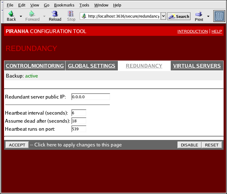
Figure 1.29. The REDUNDANCY Panel
- Redundant server public IP
- The public real IP address for the backup LVS router.
- Redundant server private IP
- The backup router's private real IP address.
The rest of the panel is for configuring the heartbeat channel, which is used by the backup node to monitor the primary node for failure.
- Heartbeat Interval (seconds)
- Sets the number of seconds between heartbeats — the interval that the backup node will check the functional status of the primary LVS node.
- Assume dead after (seconds)
- If the primary LVS node does not respond after this number of seconds, then the backup LVS router node will initiate failover.
- Heartbeat runs on port
- Sets the port at which the heartbeat communicates with the primary LVS node. The default is set to 539 if this field is left blank.
1.10.4. VIRTUAL SERVERS
The VIRTUAL SERVERS panel displays information for each currently defined virtual server. Each table entry shows the status of the virtual server, the server name, the virtual IP assigned to the server, the netmask of the virtual IP, the port number to which the service communicates, the protocol used, and the virtual device interface.
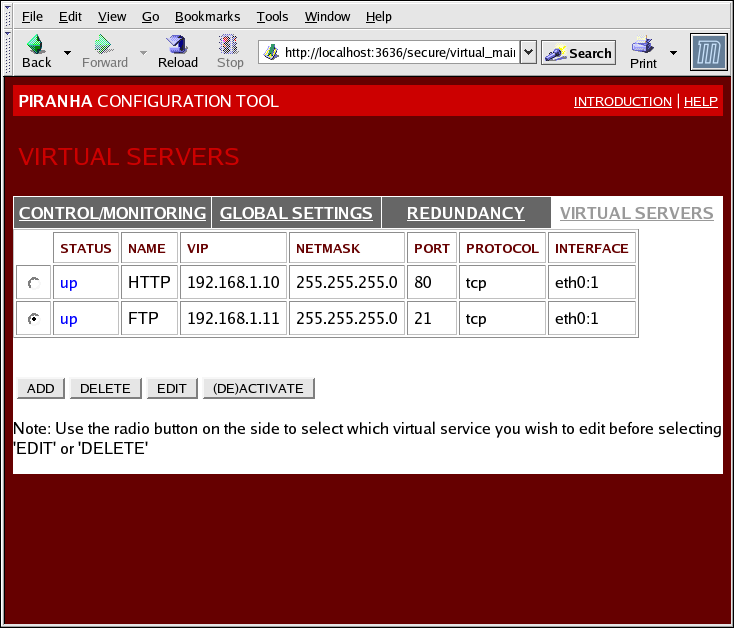
Figure 1.30. The VIRTUAL SERVERS Panel
Each server displayed in the VIRTUAL SERVERS panel can be configured on subsequent screens or subsections.
To add a service, click the button. To remove a service, select it by clicking the radio button next to the virtual server and click the button.
To enable or disable a virtual server in the table click its radio button and click the button.
After adding a virtual server, you can configure it by clicking the radio button to its left and clicking the EDIT button to display the VIRTUAL SERVER subsection.
1.10.4.1. The VIRTUAL SERVER Subsection
The VIRTUAL SERVER subsection panel shown in Figure 1.31, “The VIRTUAL SERVERS Subsection” allows you to configure an individual virtual server. Links to subsections related specifically to this virtual server are located along the top of the page. But before configuring any of the subsections related to this virtual server, complete this page and click on the button.
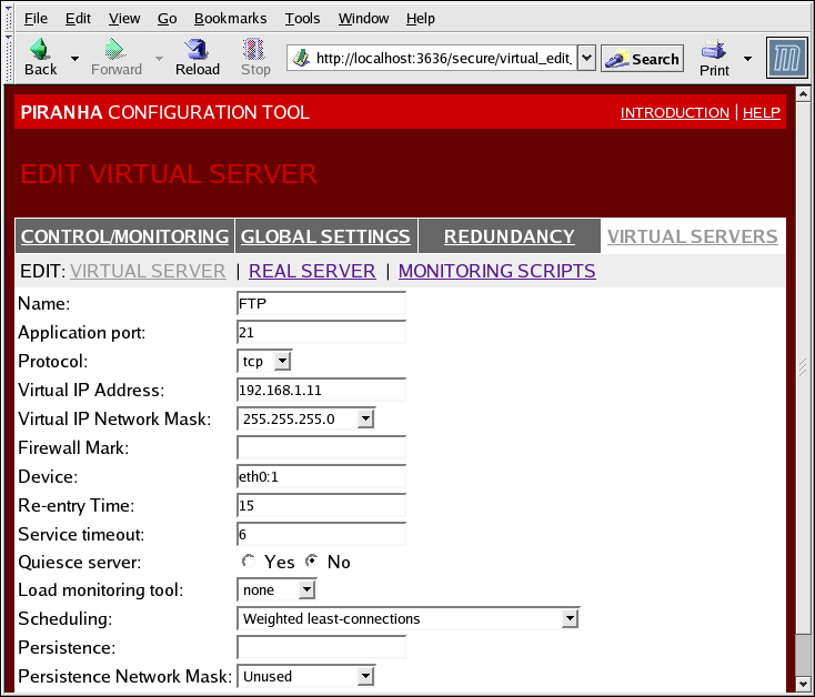
Figure 1.31. The VIRTUAL SERVERS Subsection
- Name
- A descriptive name to identify the virtual server. This name is not the hostname for the machine, so make it descriptive and easily identifiable. You can even reference the protocol used by the virtual server, such as HTTP.
- Application port
- The port number through which the service application will listen.
- Provides a choice of UDP or TCP, in a drop-down menu.
- Virtual IP Address
- The virtual server's floating IP address.
- The netmask for this virtual server, in the drop-down menu.
- Firewall Mark
- For entering a firewall mark integer value when bundling multi-port protocols or creating a multi-port virtual server for separate, but related protocols.
- Device
- The name of the network device to which you want the floating IP address defined in the Virtual IP Address field to bind.You should alias the public floating IP address to the Ethernet interface connected to the public network.
- Re-entry Time
- An integer value that defines the number of seconds before the active LVS router attempts to use a real server after the real server failed.
- Service Timeout
- An integer value that defines the number of seconds before a real server is considered dead and not available.
- Quiesce server
- When the Quiesce server radio button is selected, anytime a new real server node comes online, the least-connections table is reset to zero so the active LVS router routes requests as if all the real servers were freshly added to the cluster. This option prevents the a new server from becoming bogged down with a high number of connections upon entering the cluster.
- Load monitoring tool
- The LVS router can monitor the load on the various real servers by using either
ruporruptime. If you selectrupfrom the drop-down menu, each real server must run therstatdservice. If you selectruptime, each real server must run therwhodservice. - Scheduling
- The preferred scheduling algorithm from the drop-down menu. The default is
Weighted least-connection. - Persistence
- Used if you need persistent connections to the virtual server during client transactions. Specifies the number of seconds of inactivity allowed to lapse before a connection times out in this text field.
- To limit persistence to particular subnet, select the appropriate network mask from the drop-down menu.
1.10.4.2. REAL SERVER Subsection
Clicking on the REAL SERVER subsection link at the top of the panel displays the EDIT REAL SERVER subsection. It displays the status of the physical server hosts for a particular virtual service.
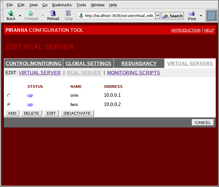
Figure 1.32. The REAL SERVER Subsection
Click the button to add a new server. To delete an existing server, select the radio button beside it and click the button. Click the button to load the EDIT REAL SERVER panel, as seen in Figure 1.33, “The REAL SERVER Configuration Panel”.
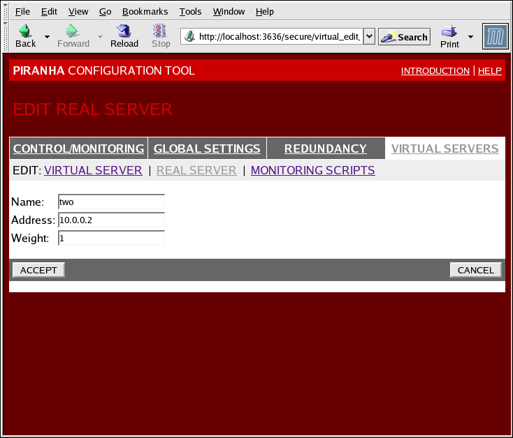
Figure 1.33. The REAL SERVER Configuration Panel
This panel consists of three entry fields:
- Name
- A descriptive name for the real server.
Note
This name is not the hostname for the machine, so make it descriptive and easily identifiable. - Address
- The real server's IP address. Since the listening port is already specified for the associated virtual server, do not add a port number.
- Weight
- An integer value indicating this host's capacity relative to that of other hosts in the pool. The value can be arbitrary, but treat it as a ratio in relation to other real servers.
1.10.4.3. EDIT MONITORING SCRIPTS Subsection
Click on the MONITORING SCRIPTS link at the top of the page. The EDIT MONITORING SCRIPTS subsection allows the administrator to specify a send/expect string sequence to verify that the service for the virtual server is functional on each real server. It is also the place where the administrator can specify customized scripts to check services requiring dynamically changing data.
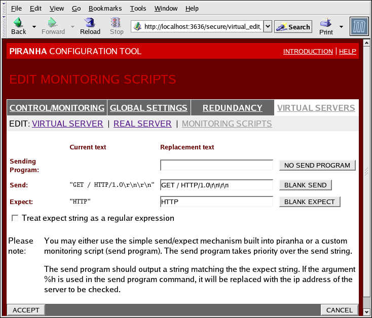
Figure 1.34. The EDIT MONITORING SCRIPTS Subsection
- Sending Program
- For more advanced service verification, you can use this field to specify the path to a service-checking script. This function is especially helpful for services that require dynamically changing data, such as HTTPS or SSL.To use this function, you must write a script that returns a textual response, set it to be executable, and type the path to it in the Sending Program field.
Note
If an external program is entered in the Sending Program field, then the Send field is ignored. - Send
- A string for the
nannydaemon to send to each real server in this field. By default the send field is completed for HTTP. You can alter this value depending on your needs. If you leave this field blank, thenannydaemon attempts to open the port and assume the service is running if it succeeds.Only one send sequence is allowed in this field, and it can only contain printable, ASCII characters as well as the following escape characters:- \n for new line.
- \r for carriage return.
- \t for tab.
- \ to escape the next character which follows it.
- Expect
- The textual response the server should return if it is functioning properly. If you wrote your own sending program, enter the response you told it to send if it was successful.