
1.10.4. VIRTUAL SERVERS
The VIRTUAL SERVERS panel displays information for each currently defined virtual server. Each table entry shows the status of the virtual server, the server name, the virtual IP assigned to the server, the netmask of the virtual IP, the port number to which the service communicates, the protocol used, and the virtual device interface.
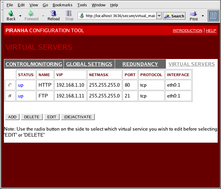
Figure 1.34. The VIRTUAL SERVERS Panel
Each server displayed in the VIRTUAL SERVERS panel can be configured on subsequent screens or subsections.
To add a service, click the button. To remove a service, select it by clicking the radio button next to the virtual server and click the button.
To enable or disable a virtual server in the table click its radio button and click the button.
After adding a virtual server, you can configure it by clicking the radio button to its left and clicking the EDIT button to display the VIRTUAL SERVER subsection.
1.10.4.1. The VIRTUAL SERVER Subsection
The VIRTUAL SERVER subsection panel shown in Figure 1.35, “The VIRTUAL SERVERS Subsection” allows you to configure an individual virtual server. Links to subsections related specifically to this virtual server are located along the top of the page. But before configuring any of the subsections related to this virtual server, complete this page and click on the button.
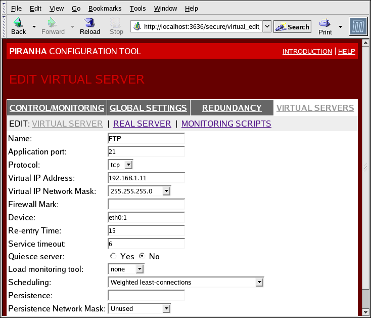
Figure 1.35. The VIRTUAL SERVERS Subsection
- Name
- A descriptive name to identify the virtual server. This name is not the hostname for the machine, so make it descriptive and easily identifiable. You can even reference the protocol used by the virtual server, such as HTTP.
- Application port
- The port number through which the service application will listen.
- Provides a choice of UDP or TCP, in a drop-down menu.
- Virtual IP Address
- The virtual server's floating IP address.
- The netmask for this virtual server, in the drop-down menu.
- Firewall Mark
- For entering a firewall mark integer value when bundling multi-port protocols or creating a multi-port virtual server for separate, but related protocols.
- Device
- The name of the network device to which you want the floating IP address defined in the Virtual IP Address field to bind.You should alias the public floating IP address to the Ethernet interface connected to the public network.
- Re-entry Time
- An integer value that defines the number of seconds before the active LVS router attempts to use a real server after the real server failed.
- Service Timeout
- An integer value that defines the number of seconds before a real server is considered dead and not available.
- Quiesce server
- When the Quiesce server radio button is selected, anytime a new real server node comes online, the least-connections table is reset to zero so the active LVS router routes requests as if all the real servers were freshly added to the cluster. This option prevents the a new server from becoming bogged down with a high number of connections upon entering the cluster.
- Load monitoring tool
- The LVS router can monitor the load on the various real servers by using either
ruporruptime. If you selectrupfrom the drop-down menu, each real server must run therstatdservice. If you selectruptime, each real server must run therwhodservice. - Scheduling
- The preferred scheduling algorithm from the drop-down menu. The default is
Weighted least-connection. - Persistence
- Used if you need persistent connections to the virtual server during client transactions. Specifies the number of seconds of inactivity allowed to lapse before a connection times out in this text field.
- To limit persistence to particular subnet, select the appropriate network mask from the drop-down menu.