
Red Hat Training
A Red Hat training course is available for Red Hat Decision Manager
Chapter 2. Decision Model and Notation (DMN)
Decision Model and Notation (DMN) is a standard established by the Object Management Group (OMG) for describing and modeling operational decisions. DMN defines an XML schema that enables DMN models to be shared between DMN-compliant platforms and across organizations so that business analysts and business rules developers can collaborate in designing and implementing DMN decision services. The DMN standard is similar to and can be used together with the Business Process Model and Notation (BPMN) standard for designing and modeling business processes.
For more information about the background and applications of DMN, see the OMG Decision Model and Notation specification.
2.1. Creating the traffic violations DMN decision requirements diagram (DRD)
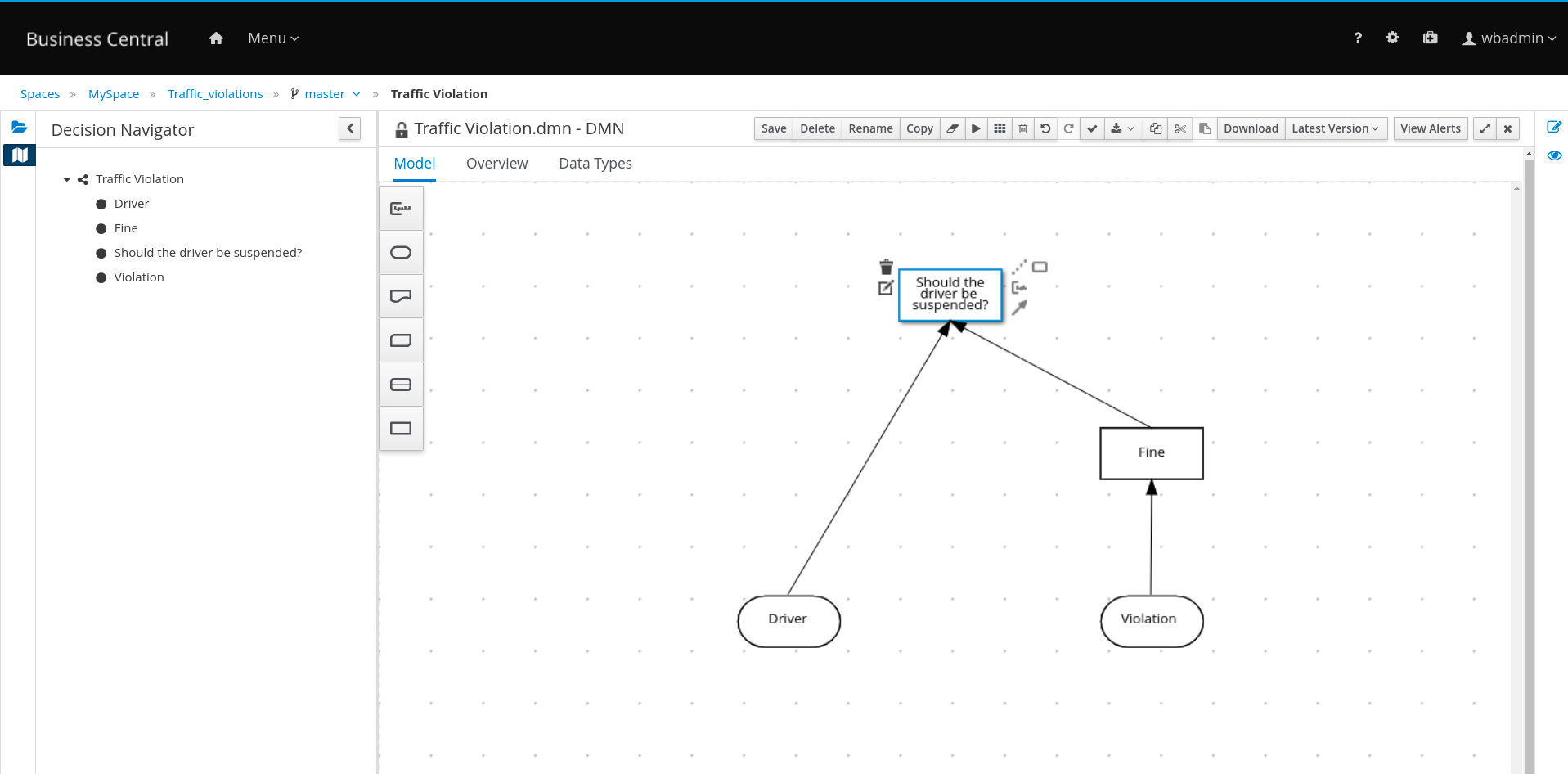
A decision requirements diagram (DRD) is a visual representation of your DMN model. Use the DMN designer in Business Central to design the DRD for the traffic violations project and to define the decision logic of the DRD components.
Figure 2.1. DRD for the Traffic Violations example
Prerequisite
- You have created the traffic violations project in Business Central.
Procedure
- On the traffic-violation project’s home screen, click Add Asset to open the Add Asset screen.
Click DMN to open the Create new DMN dialog.
-
Enter
Traffic Violationin the Name field. -
From the Package list, select
org.kie.example.traffic.traffic_violations. - Click Ok to open the DMN asset in the DMN designer.
-
Enter
-
In the DMN designer canvas, drag two input nodes to the canvas. Double-click the input nodes and rename them as
DriverandViolation. -
Drag a decision node to the canvas. Double-click and rename it as
Fine. -
Click the Violation input node and select the
Create DMN Information Requirementoption to connect to theFinedecision node. -
Drag another decision node to the canvas and double-click and rename it as
Should the driver be suspended?. -
Click the Driver input node and select the
Create DMN Information Requirementoption to connect to theShould the driver be suspended?decision node. -
Click the Fine decision node and select the
Create DMN Information Requirementoption to connect to theShould the driver be suspended?decision node. - Click Save to open the Confirm Save dialog box and click Save again.
2.2. Creating the traffic violations DMN custom data types
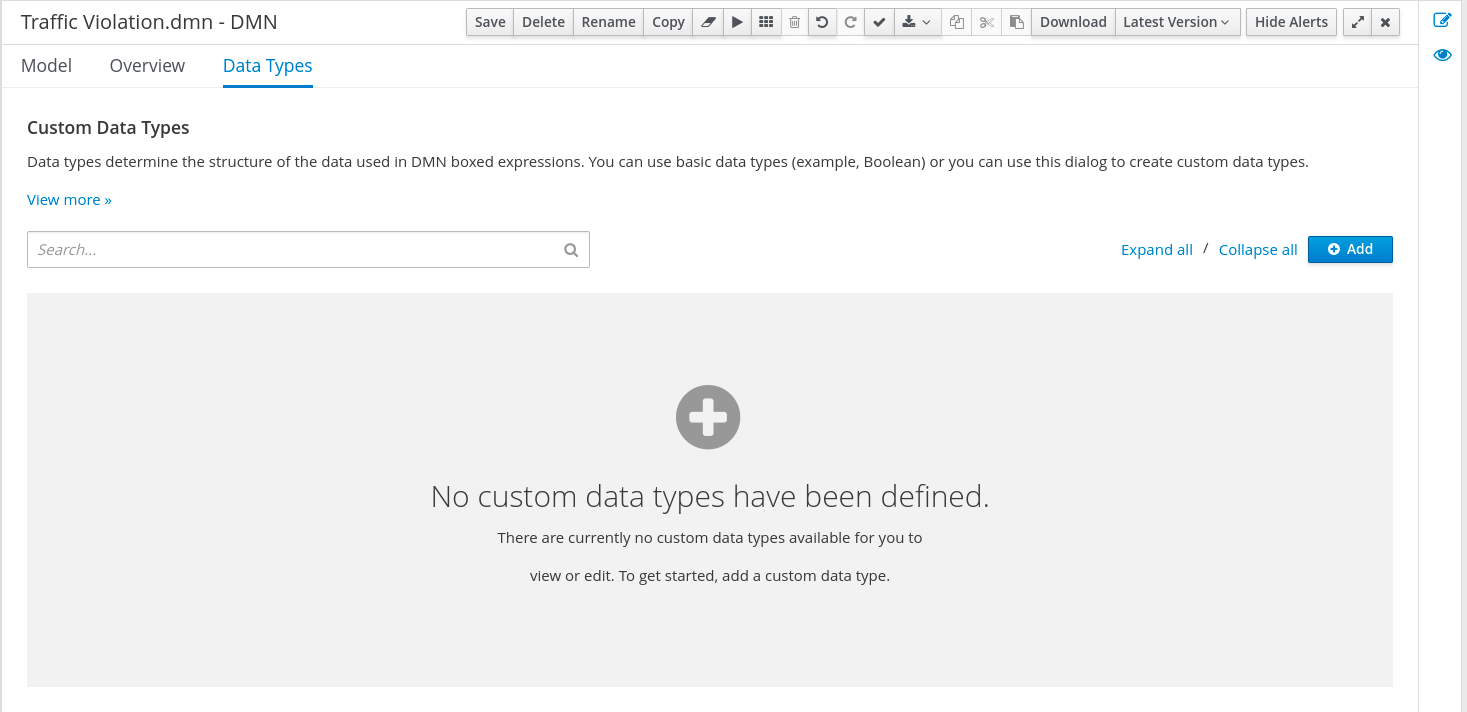
DMN data types determine the structure of the data that you use within a table, column, or field in a DMN boxed expression for defining decision logic. You can use default DMN data types (such as string, number, or boolean) or you can create custom data types to specify additional fields and constraints that you want to implement for the boxed expression values. Use the DMN designer’s Data Types tab in Business Central to define the custom data types for the traffic violations project.
Figure 2.2. The custom data types tab
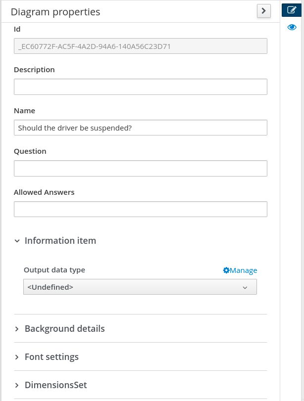
Alternately, you can also access the Data Types tab from the Diagram properties tab on the right. From the Diagram properties tab, click Manage from Output data types under Information item.
Figure 2.3. Diagram properties tab
The following tables list the Violation, Driver, and Fine custom data types that you will create for this project.
Table 2.1. Driver custom data types
| Name | Type |
|---|---|
| tDriver | Structure |
| Name | string |
| Age | number |
| State | string |
| City | string |
| Points | number |
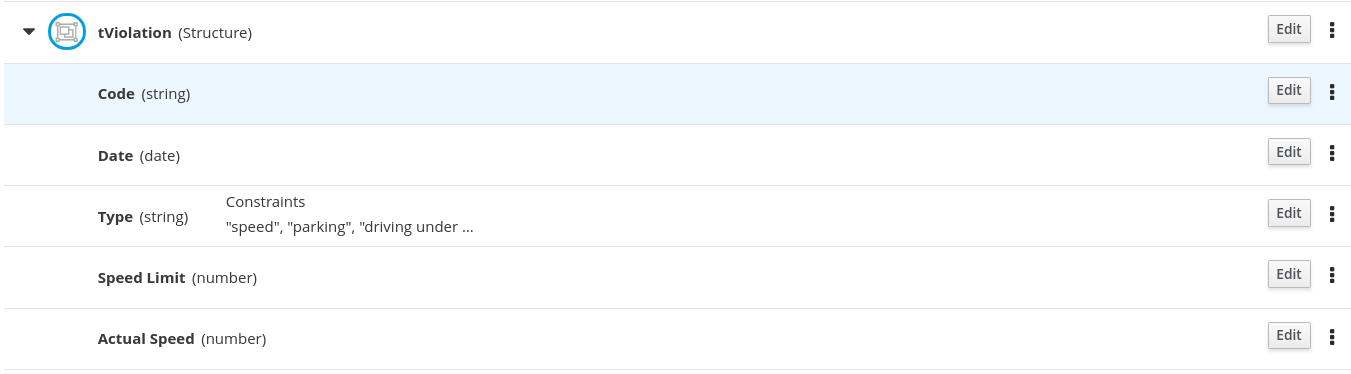
Table 2.2. Violation custom data types
| Name | Type |
|---|---|
| tViolation | Structure |
| Code | string |
| Date | date |
| Type | string |
| Speed Limit | number |
| Actual Speed | number |
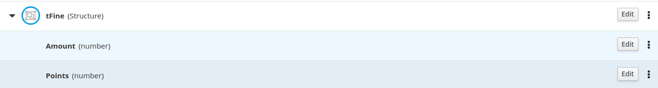
Table 2.3. Fine custom data types
| Name | Type |
|---|---|
| tFine | Structure |
| Amount | number |
| Points | number |
Prerequisite
- You have created the traffic violations DMN decision requirements diagram (DRDs) in Business Central.
Procedure
- From the Data Types tab, click Add.
First, create the tDriver custom data type. Enter
tDriveras the Name and selectStructureas the Type. Click Save for each data type that you add.Figure 2.4. The tDriver custom data type
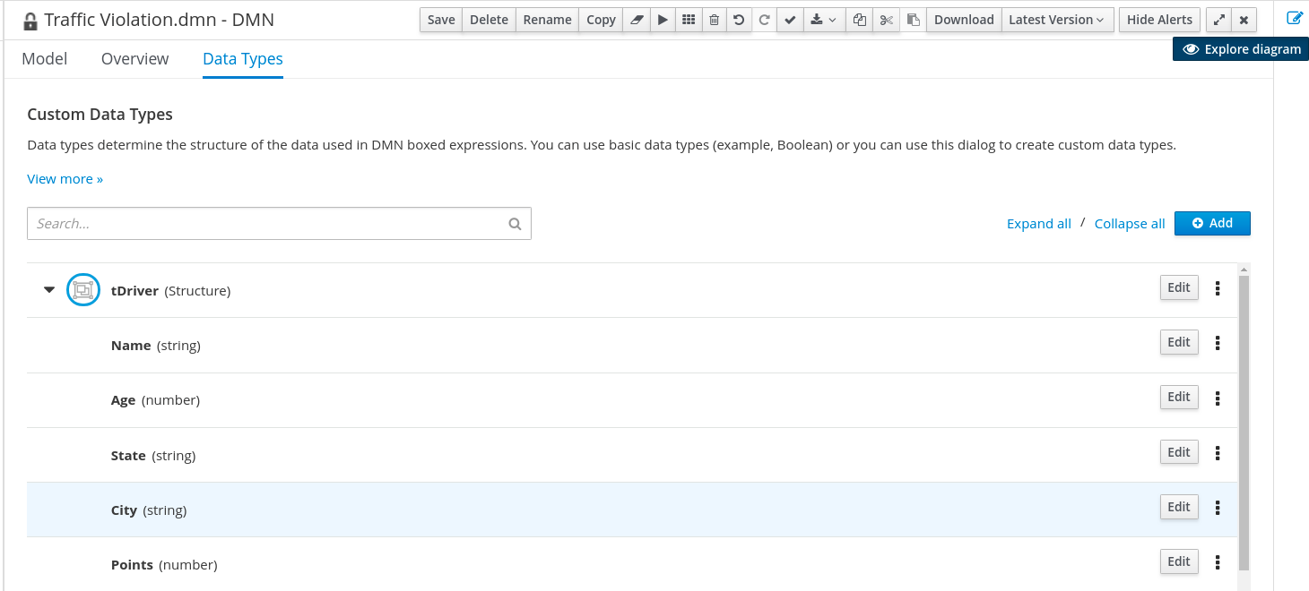
Next to the tDriver data type, click the three vertical dots, select Insert nested field, and add the following nested data types. Click Save for each data type that you add.
- Name (string)
- Age (number)
- State (string)
- City (string)
- Points (number)
Next, create the tViolation data type. From the Data Types tab, click Add.
Figure 2.5. The tViolation custom data type
-
Enter
tViolationas the Name and selectStructureas the Type. Click Save to save the data type. Next to the tViolation data type, click the three vertical dots, select Insert nested field, and add the following nested data types. Click Save for each data type that you add.
- Code (string)
- Date (date)
- Type (string)
- Speed Limit (number)
- Actual Speed (number)
For the nested
Typedata type that you created, click Edit → Constraints → Enumeration and add the following constraints. Click the check icon to save each enumeration constraint that you add.
-
"speed" -
"parking" -
"Driving under the influence?"
-
Finally, create the tFine data type. From the Data Types tab, click Add.
Figure 2.6. The tFine custom data type
-
Enter
tFineas the Name and selectStructureas the Type. Click Save to save the data type. Next to the tFine data type, click the three vertical dots, select Insert nested field, and add the following nested data types. Click Save for each data type that you add.
- Amount (number)
- Points (number)
- Once all the three custom data types are created, click Save to open the Confirm Save dialog box and click Save again.
2.3. Assigning custom data types to the DRD input and decision nodes
After you create the DMN custom data types, assign them to the appropriate DMN Input Data and DMN Decision nodes in the traffic violations DRD.
Prerequisite
- You have created the traffic violations DMN custom data types in Business Central.
Procedure
- Click the Model tab on the DMN designer and click Diagram properties in the top-right corner of the DMN designer to expose the DRD properties.
-
In the DRD, select the Driver input data node and in the Diagram properties panel, set Output data type to
tDriver. -
Select the Violation input data node and set the Output data type to
tViolation. -
Select the Fine input data node and set the Output data type to
tFine. Select the Should the driver be suspended? decision node and set the following properties:
-
Output data type:
string -
Question:
Should the driver be suspended due to points on his driver license? -
Allowed Answers:
"Yes","No"
-
Output data type:
- Click Save to open the Confirm Save dialog box and click Save again.
You have assigned the custom data types to your DRD’s input and decision nodes.
2.4. Defining the traffic violations DMN decision logic
To calculate the fine and to decide whether the driver is to be suspended or not, you can define the traffic violations DMN decision logic using a DMN decision table and context boxed expression.
Figure 2.7. Fine decision table
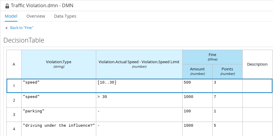
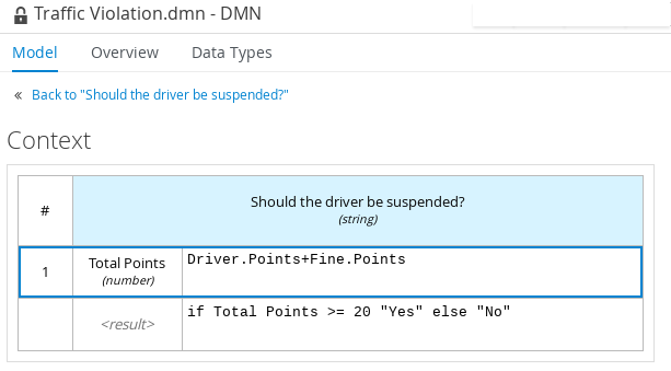
Figure 2.8. Should the driver be suspended? context boxed expression
Prerequisite
- You have assigned the DMN custom data types to the appropriate decision and input nodes in the traffic violations DRD in Business Central.
Procedure
- To calculate fine, in the DMN designer canvas, select the Fine decision node and click the Edit icon to open the DMN boxed expression designer.
- Click Select expression → Decision Table.
- For the Violation.Date, Violation.Code, and Violation.Speed Limit parameter fields, right-click and select Delete Input Clause for each field.
-
Click the Violation.Actual Speed column header and enter the expression
Violation.Actual Speed - Violation.Speed Limitin the Name field. -
Right-click the Fine parameter field and select either
Insert Output Clause leftorInsert Output Clause right. -
Click the output-2 column sub-header, enter
Amountin the Name field, and selectnumberfrom the Data Type field. -
Similarly, click the output-1 column sub-header, enter
Pointsin the Name field, and selectnumberfrom the Data Type field. Next, enter the following values in the first row of the decision table:
-
Violation.Type:
"speed" -
Violation.Actual Speed - Violation.Speed Limit:
[10..30] -
Amount:
500 Points:
3Right-click the first row and select
Insert rule belowto add another row.
-
Violation.Type:
Enter the following values in the second row of the decision table:
-
Violation.Type:
"speed" -
Violation.Actual Speed - Violation.Speed Limit:
> 30 -
Amount:
1000 Points:
7Right-click the second row and select
Insert rule belowto add another row.
-
Violation.Type:
Enter the following values in the third row of the decision table:
-
Violation.Type:
"parking" -
Violation.Actual Speed - Violation.Speed Limit:
- -
Amount:
100 Points:
1Right-click the third row and select
Insert rule belowto add another row.
-
Violation.Type:
Enter the following values in the fourth row of the decision table:
-
Violation.Type:
"driving under the influence" -
Violation.Actual Speed - Violation.Speed Limit:
- -
Amount:
1000 -
Points:
5
-
Violation.Type:
- Click Save to open the Confirm Save dialog box and click Save again.
- To define the driver suspension rule, return to the DMN designer canvas, select the Should the driver be suspended? decision node, and click the Edit icon to open the DMN boxed expression designer.
- Click Select expression → Context.
-
Click ContextEntry-1, enter
Total Pointsas the Name, and selectnumberas the Data Type. -
Click the cell next to Total Points, select
Literal Expressionfrom the context menu, and enterDriver.Points + Fine.Pointsas the expression. -
In the cell below Driver.Points + Fine.Points, select
Literal Expressionfrom the context menu, and enterif Total Points >= 20 then "Yes" else "No". Click Save to open the Confirm Save dialog box and click Save again.
You have defined how to calculate the fine and the context for deciding when to suspend the driver. You can navigate to the traffic-violation project page and click Build to build the example project and address any errors noted in the Alerts panel.