
Object Gateway for Production Guide
Planning, designing and deploying Ceph Storage clusters and Ceph Object Gateway clusters for production.
Abstract
Chapter 1. Introduction
Welcome to the Ceph Object Gateway for Production guide. This guide covers topics for building Ceph Storage clusters and Ceph Object Gateway clusters for production use.
1.1. Audience
This guide is for those who intend to deploy a Ceph Object Gateway environment for production. It provides a sequential series of topics for planning, designing and deploying a production Ceph Storage cluster and Ceph Object Gateway cluster with links to general Ceph documentation where appropriate.
1.2. Assumptions
This guide assumes the reader has a basic understanding of the Ceph Storage Cluster and the Ceph Object Gateway. Readers with no Ceph experience should consider setting up a small Ceph test environment or using the Ceph Sandbox Environment to get familiar with Ceph concepts before proceeding with this guide.
This guide assumes a single-site cluster consisting of a single Ceph Storage cluster and multiple Ceph Object Gateway instances in the same zone. This guide assumes the single-site cluster will expand to a multi-zone and multi-site cluster by repeating the procedures in this guide for each zone group and zone with the naming modifications required for secondary zone groups and zones.
1.3. Scope
This guide covers the following topics when setting up a Ceph Storage Cluster and a Ceph Object Gateway for production:
This document is intended to complement the hardware, installation, administration and Ceph Object Gateway guides. This guide does not replace the other guides.
Chapter 2. Planning a Cluster
Planning a cluster for use with the Ceph Object Gateway involves several important considerations:
These factors will have a significant influence when considering hardware. Consider these factors carefully before selecting hardware.
2.1. Identifying Use Cases
Ceph Storage is capable of serving many different types of storage use cases. For Ceph Object Storage, the typical use cases are:
- Throughput-optimized: A throughput-optimized cluster seeks to ensure fast data access. Host bus adapters (HBAs), storage media with fast sequential read/write characteristics and high network bandwidth provide capability for applications such as graphics, streaming audio and streaming video. Throughput-optimized optimized clusters also consider whether write performance is a consideration. Throughput-optimized clusters that use SSDs for journaling realize substantially better write performance, which can be important for applications like storing CCTV streams. Throughput-optimized clusters should consider the throughput characteristics of a Host Bus Adapter (HBA) controller and network throughput for intensive applications such as streaming 4K video. HBA-based hardware controllers offer significant performance improvements over on-board controllers.
- Capacity-optimized: A capacity-optimized cluster seeks to ensure the lowest cost per terabyte of storage. Capacity-optimized clusters often use the least expensive storage media and often avoid the added expense of separate SSD journals for applications such as archiving infrequently accessed legacy financial records, old emails, etc.
- IOPS-optimized: An IOPS-optimized cluster seeks to provide high performance for read- and write-intensive workloads. While IOPS-optimized workloads are not as common for Ceph Object Gateways, they can be supported with SSD, Flash memory or NVMe CRUSH hierarchies.
Carefully consider the storage use case(s) BEFORE considering hardware, because it can significantly impact the price and performance of the cluster. For example, if the use case is capacity-optimized and the hardware is better suited to a throughput-optimized use case, the hardware will be more expensive than necessary. Conversely, if the use case is throughput-optimized and the hardware is better suited to a capacity-optimized use case, the cluster may suffer from poor performance.
Also, note that since Ceph Object Gateway supports storage policies, it is possible to create CRUSH hierarchies for ALL of the foregoing scenarios and invoke them with storage policies supported in the APIs. See Creating Data Placement Strategies for details.
2.2. Selecting Data Durability Methods
Cluster design should also consider the data durability strategy. Ceph Storage uses either replication or erasure coding to ensure data durability.
Replication stores one or more redundant copies of the data across failure domains in case of a hardware failure. However, redundant copies of data can become expensive at scale. For example, to store 1 petabyte of data with triple replication would require a cluster with at least 3 petabytes of storage capacity.
The Erasure coding section of the Storage Strategies Guide for Red Hat Ceph Storage 4 describes how erasure coding stores data as data chunks and coding chunks. In the event of a lost data chunk, erasure coding can recover the lost data chunk with the remaining data chunks and coding chunks. Erasure coding is substantially more economical than replication. For example, using erasure coding with 8 data chunks and 3 coding chunks provides the same redundancy as 3 copies of the data. However, such an encoding scheme uses approximately 1.5x of the initial data stored compared to 3x with replication.
ONLY the data storage pool can use erasure coding. Pools storing service data and bucket indexes use replication.
2.3. Considering Multi-site Deployment
Another important aspect of designing a cluster is to determine if the cluster will be in one data center site or span multiple data center sites. Multi-site clusters benefit from geographically distributed failover and disaster recovery, such as long-term power outages, earthquakes, hurricanes, floods or other disasters. Additionally, multi-site clusters in an active-active configuration can direct client applications to the closest available cluster in the manner of content delivery networks. Placing data as close to the client as possible is increasingly important for throughput intensive workloads such as streaming 4k video.
For details of multi-site clusters, see the Multi-site chapter in the Ceph Object Gateway Configuration and Administration Guide for Red Hat Ceph Storage 4.
Red Hat recommends identifying realm, zone group and zone names BEFORE creating Ceph Storage pools. Some pool names should be pre-pended with the zone name by convention.
Chapter 3. Considering Hardware
Considering hardware is an important part of building Ceph Storage clusters and Ceph Object Gateway clusters for production environments. High-level considerations include:
Consider these factors BEFORE identifying and purchasing computing and networking hardware for the cluster.
3.1. Considering Storage Sizing
One of the most important factors in designing a cluster is to determine the storage requirements (sizing). Ceph Storage is designed to scale into petabytes and beyond. The following examples are common sizes for Ceph storage clusters.
- Small: 250 terabytes
- Medium: 1 petabyte
- Large: 2 petabytes or more.
Sizing should include current needs and the needs of the near future. Consider the rate at which the gateway client will add new data to the cluster. That may differ from use-case to use-case. For example, recording CCTV video, 4k video or medical imaging may add significant amounts of data far more quickly then less storage intensive information such as financial market data. Additionally, consider that data durability methods such as replication versus erasure coding will have a significant impact on the storage media required.
For additional information on sizing, see the Red Hat Ceph Storage Hardware Selection Guide and its associated links for selecting OSD hardware.
3.2. Considering Storage Density
Another important aspect of cluster design includes storage density. Generally, a cluster should store data across at least 10 nodes to ensure reasonable performance when replicating, backfilling and recovery. If a node fails, with at least 10 nodes in the cluster, only 10% of the data has to move to the surviving nodes. If the number of nodes is substantially less, a higher percentage of the data must move to the surviving nodes. Additionally, the full_ratio and near_full_ratio need to be set to accommodate a node failure to ensure that the cluster can write data. For this reason, it is is important to consider storage density. Higher storage density isn’t necessarily a good idea.
Another factor that favors more nodes over higher storage density is erasure coding. When writing an object using erasure coding and using node as the minimum CRUSH failure domain, the cluster will need as many nodes as data and coding chunks. For example, a cluster using k=8, m=3 should have at least 11 nodes so that each data or coding chunk is stored on a separate node.
Hot-swapping is also an important consideration. Most modern servers support drive hot-swapping. However, some hardware configurations require removing more than one drive to replace a drive. Red Hat recommends avoiding such configurations, because they can bring down more OSDs than required when swapping out failed disks.
3.3. Considering Network Hardware
A major advantage of Ceph Storage is that it allows scaling capacity, IOPS and throughput independently. An important aspect of a cloud storage solution is that clusters can run out of IOPS due to network latency and other factors or run out of throughput due to bandwidth constraints long before the clusters run out of storage capacity. This means that the network hardware configuration must support the use case(s) in order to meet price/performance targets. Network performance is increasingly important when considering the use of SSDs, flash, NVMe, and other high performance storage methods.
Another important consideration of Ceph Storage is that it supports a front side or public network for client and monitor data, and a back side or cluster network for heart beating, data replication and recovery. This means that the back side or cluster network will always require more network resources than the front side or public network. Depending upon whether the data pool uses replication or erasure coding for data durability, the network requirements for the back side or cluster network should be quantified appropriately.
Finally, verify network throughput before installing and testing Ceph. Most performance-related problems in Ceph usually begin with a networking issue. Simple network issues like a kinked or bent Cat-6 cable could result in degraded bandwidth. Use a minimum of 10Gbe for the front side network. For large clusters, consider using 40Gbe for the backend or cluster network. Alternatively, use LACP mode 4 to bond networks. Additionally, use jumbo frames (MTU 9000), especially on the backend or cluster network.
3.4. Considering Uninterrupted Power Supplies
Since Ceph writes are atomic—all or nothing—it isn’t a requirement to invest in uninterruptable power supplies (UPS) for Ceph OSD nodes. However, Red Hat recommends investing in UPSs for Ceph Monitor nodes. Monitors use leveldb, which is sensitive to synchronous write latency. A power outage could cause corruption, requiring technical support to restore the state of the cluster.
Ceph OSDs may benefit from the use of a UPS if a storage controller uses a writeback cache. In this scenario, a UPS may help prevent filesystem corruption during a power outage if the controller doesn’t flush the writeback cache in time.
3.5. Selecting Hardware for Use Cases
A major advantage of Ceph Storage is that it can be configured to support many use cases. Generally, Red Hat recommends configuring OSD hosts identically for a particular use case. The three primary use cases for a Ceph Storage cluster are:
- IOPS optimized
- Throughput optimized
- Capacity optimized
Since these use cases typically have different drive, HBA controller and networking requirements among other factors, configuring a series of identical hosts to facilitate all of these use cases with a single node configuration is possible, but is not necessarily recommended.
Using the same hosts to facilitate multiple CRUSH hierarchies will involve the use of logical, rather than actual host names in the CRUSH map. Additionally, deployment tools such as Ansible would need to consider a group for each use case, rather than deploying all OSDs in the default [osds] group.
Generally, it is easier to configure and manage hosts that serve a single use case, such as high IOPS, high throughput, or high capacity.
3.6. Selecting Media for Indexes
When selecting OSD hardware for use with a Ceph Object Gateway--irrespective of the use case--it is required to have an OSD node that has at least one high performance drive, either an SSD or NVMe drive, for storing the index pool. This is particularly important when buckets contain a large number of objects.
For Red Hat Ceph Storage running Bluestore, Red Hat recommends deploying an NVMe drive as a block.db device, rather than as a separate pool.
Ceph Object Gateway index data is written only into an object map (OMAP). OMAP data for BlueStore resides on the block.db device on an OSD. When an NVMe drive functions as a block.db device for an HDD OSD and when the index pool is backed by HDD OSDs, the index data will ONLY be written to the block.db device. As long as the block.db partition/lvm is sized properly at 4% of block, this configuration is all that is needed for BlueStore.
Red Hat does not support HDD devices for index pools. For more information on supported configurations, see the Red Hat Ceph Storage: Supported configurations article.
An index entry is approximately 200 bytes of data, stored as an OMAP in rocksdb. While this is a trivial amount of data, some uses of Ceph Object Gateway can result in tens or hundreds of millions of objects in a single bucket. By mapping the index pool to a CRUSH hierarchy of high performance storage media, the reduced latency provides a dramatic performance improvement when buckets contain very large numbers of objects.
In a production cluster, a typical OSD node will have at least one SSD or NVMe drive for storing the OSD journal and the index pool or block.db device, which will use separate partitions or logical volumes when using the same physical drive.
3.7. Selecting Media for Monitor Nodes
Ceph monitors use leveldb, which is sensitive to synchronous write latency. Red Hat strongly recommends using SSDs to store monitor data. Ensure that the selected SSDs have sufficient sequential write and throughput characteristics.
Chapter 4. Configuring a Cluster
The initial configuring of a production cluster is identical to configuring a proof-of-concept system. The only material difference is that the initial deployment will use production-grade hardware. First, follow the Requirements for Installing Red Hat Ceph Storage chapter of the Red Hat Ceph Storage 4 Installation Guide and execute the appropriate steps for each node. The following sections provide additional guidance relevant to production clusters.
4.1. Naming Hosts
When naming hosts, consider their use case and performance profile. For example, if the hosts will store client data, consider naming them according to their hardware configuration and performance profile. For example:
-
data-ssd-1,data-ssd-2 -
hot-storage-1,hot-storage-2 -
sata-1,sata-2 -
sas-ssd-1,sas-ssd-2
The naming convention may make it easier to manage the cluster and troubleshoot hardware issues as they arise.
If the host contains hardware for multiple use cases—for example, the host contains SSDs for data, SAS drives with SSDs for journals, and SATA drives with co-located journals for cold storage—choose a generic name for the host. For example:
-
osd-node-1osd-node-2
Generic host names can be extended when using logical host names in the CRUSH hierarchy as needed. For example:
-
osd-node-1-ssdosd-node-1-sataosd-node-1-sas-ssdosd-node-1-bucket-index -
osd-node-2-ssdosd-node-2-sataosd-node-2-sas-ssdosd-node-2-bucket-index
See Using Logical Host Names in a CRUSH Map for additional details.
4.2. Tuning the Kernel
Production clusters benefit from tuning the operating system, specifically limits and memory allocation. Ensure that adjustments are set for all nodes within the cluster. Consult Red Hat support for additional guidance.
4.2.1. Reserving Free Memory for OSDs
To help prevent insufficient memory-related errors during OSD memory allocation requests, set the os_tuning_params option in the group_vars/all.yml on ceph-ansible node. This option specifies the amount of physical memory to keep in reserve. The recommended settings are based on the amount of system RAM. For example:
For 64GB RAM, reserve 1GB.
vm.min_free_kbytes = 1048576
For 128GB RAM, reserve 2GB.
vm.min_free_kbytes = 2097152
For 256GB RAM, reserve 3GB.
vm.min_free_kbytes = 3145728
4.2.2. Increasing File Descriptors
The Ceph Object Gateway may hang if it runs out of file descriptors. Modify /etc/security/limits.conf on Ceph Object Gateway nodes to increase the file descriptors for the Ceph Object Gateway. For example:
ceph soft nofile unlimited
4.2.3. Adjusting ulimit on Large Clusters
For system administrators that will run Ceph administrator commands on large clusters—for example, 1024 OSDs or more—create an /etc/security/limits.d/50-ceph.conf file on each node that will run administrator commands with the following contents:
<username> soft nproc unlimited
Replace <username> with the name of the non-root account that will run Ceph administrator commands.
The root user’s ulimit is already set to "unlimited" by default on Red Hat Enterprise Linux.
4.3. Configuring Ansible Groups
This procedure is only pertinent for deploying Ceph using Ansible. The ceph-ansible package is already configured with a default osds group. If the cluster will only have one use case and storage policy, proceed with the procedure documented in the Installing a Red Hat Ceph Storage Cluster section of the Red Hat Ceph Storage Installation Guide. If the cluster will support multiple use cases and storage policies, create a group for each one. Each use case should copy /usr/share/ceph-ansible/group_vars/osd.sample to a file named for the group name. For example, if the storage cluster has IOPS-optimized, throughput-optimized and capacity-optimized use cases, create separate files representing the groups for each use case:
cd /usr/share/ceph-ansible/group_vars/
cp osds.sample osds-iops
cp osds.sample osds-throughput
cp osds.sample osds-capacity
Then, configure each file according to the use case.
Once the group variable files are configured, edit the site.yml file to ensure that it includes each new group. For example:
- hosts: osds-iops
  gather_facts: false
  become: True
  roles:
  - ceph-osd

- hosts: osds-throughput
  gather_facts: false
  become: True
  roles:
  - ceph-osd

- hosts: osds-capacity
  gather_facts: false
  become: True
  roles:
  - ceph-osd
Finally, in the /etc/ansible/hosts file, place the OSD nodes associated to a group under the corresponding group name. For example:
[osds-iops]
<ceph-host-name> devices="[ '<device_1>', '<device_2>' ]"

[osds-throughput]
<ceph-host-name> devices="[ '<device_1>', '<device_2>' ]"

[osds-capacity]
<ceph-host-name> devices="[ '<device_1>', '<device_2>' ]"
4.4. Configuring Ceph
Generally, administrators should configure the Red Hat Ceph Storage cluster before the initial deployment using the Ceph Ansible configuration files found in the /usr/share/ceph-ansible/group_vars directory.
As indicated in the Installing a Red Hat Ceph Storage Cluster section of the Red Hat Ceph Storage installation guide:
-
For Monitors, create a
mons.ymlfile from thesample.mons.ymlfile. -
For OSDs, create an
osds.ymlfile from thesample.osds.ymlfile. -
For the cluster, create an
all.ymlfile from thesample.all.ymlfile.
Modify the settings as directed in the Installation Guide.
Also refer to Installing the Ceph Object Gateway, and create an rgws.yml file from sample.rgws.yml.
- NOTE
-
The settings in the foregoing files may take precedence over settings in
ceph_conf_overrides.
To configure settings with no corresponding values in the mons.yml, osds.yml, or rgws.yml file, add configuration settings to the ceph_conf_overrides section of the all.yml file. For example:
ceph_conf_overrides:
   global:
      osd_pool_default_pg_num: <number>
See the Configuration File Structure for details on configuration file sections.
There are syntactic differences between specifying a Ceph configuration setting in an Ansible configuration file and how it renders in the Ceph configuration file.
In RHCS version 3.1 and earlier, the Ceph configuration file uses ini style notion. Sections like [global] in the Ceph configuration file should be specified as global:, indented on their own lines. It is also possible to specify configuration sections for specific daemon instances. For example, placing osd.1: in the ceph_conf_overrides section of the all.yml file will render as [osd.1] in the Ceph configuration file and the settings under that section will apply to osd.1 only.
Ceph configuration settings SHOULD contain dashes (-) or underscores (_) rather than spaces, and should terminate with a colon (:), not an equal sign (=).
Before deploying the Ceph cluster, consider the following configuration settings. When setting Ceph configuration settings, Red Hat recommends setting the values in the ceph-ansible configuration files, which will generate a Ceph configuration file automatically.
4.4.1. Setting the Journal Size
Set the journal size for the Ceph cluster. Configuration tools such as Ansible may have a default value. Generally, the journal size should find the product of the synchronization interval and the slower of the disk and network throughput, and multiply the product by two (2).
For details, see the Journal Settings section in the Configuration Guide for Red Hat Ceph Storage 4.
4.4.2. Adjusting Backfill & Recovery Settings
I/O is negatively impacted by both backfilling and recovery operations, leading to poor performance and unhappy end users. To help accommodate I/O demand during a cluster expansion or recovery, set the following options and values in the Ceph Configuration file:
[osd]
osd_max_backfills = 1
osd_recovery_max_active = 1
osd_recovery_op_priority = 1
4.4.3. Adjusting the Cluster Map Size
For Red Hat Ceph Storage version 2 and earlier, when the cluster has thousands of OSDs, download the cluster map and check its file size. By default, the ceph-osd daemon caches 500 previous osdmaps. Even with deduplication, the map may consume a lot of memory per daemon. Tuning the cache size in the Ceph configuration file may help reduce memory consumption significantly. For example:
[global]
osd_map_message_max=10

[osd]
osd_map_cache_size=20
osd_map_max_advance=10
osd_map_share_max_epochs=10
osd_pg_epoch_persisted_max_stale=10
For Red Hat Ceph Storage version 3 and later, the ceph-manager daemon handles PG queries, so the cluster map should not impact performance.
4.4.4. Adjusting Scrubbing
By default, Ceph performs light scrubbing daily and deep scrubbing weekly. Light scrubbing checks object sizes and checksums to ensure that PGs are storing the same object data. Over time, disk sectors can go bad irrespective of object sizes and checksums. Deep scrubbing checks an object’s content with that of its replicas to ensure that the actual contents are the same. In this respect, deep scrubbing ensures data integrity in the manner of fsck, but the procedure imposes an I/O penalty on the cluster. Even light scrubbing can impact I/O.
The default settings may allow Ceph OSDs to initiate scrubbing at inopportune times such as peak operating times or periods with heavy loads. End users may experience latency and poor performance when scrubbing operations conflict with end user operations.
To prevent end users from experiencing poor performance, Ceph provides a number of scrubbing settings that can limit scrubbing to periods with lower loads or during off-peak hours. For details, see the Scrubbing the OSD section in the Red Hat Ceph Storage Configuration Guide.
If the cluster experiences high loads during the day and low loads late at night, consider restricting scrubbing to night time hours. For example:
[osd]
osd_scrub_begin_hour = 23   #23:01H, or 10:01PM.
osd_scrub_end_hour = 6      #06:01H or 6:01AM.
If time constraints aren’t an effective method of determining a scrubbing schedule, consider using the osd_scrub_load_threshold. The default value is 0.5, but it could be modified for low load conditions. For example:
[osd]
osd_scrub_load_threshold = 0.25
4.4.5. Increase objecter_inflight_ops
In RHCS 3.0 and earlier releases, consider increasing objecter_inflight_ops to the default size for version 3.1 and later releases to improve scalability.
objecter_inflight_ops = 24576
4.4.6. Increase rgw_thread_pool_size
In RHCS 3.0 and earlier releases, consider increasing rgw_thread_pool_size to the default size for version 3.1 and later releases to improve scalability. For example:
rgw_thread_pool_size = 512
4.4.7. Adjusting Garbage Collection Settings
The Ceph Object Gateway allocates storage for new and overwritten objects immediately. Additionally, the parts of a multi-part upload also consume some storage.
The Ceph Object Gateway purges the storage space used for deleted objects after deleting the objects from the bucket index. Similarly, the Ceph Object Gateway will delete data associated with a multi-part upload after the multi-part upload completes or when the upload has gone inactive or failed to complete for a configurable amount of time. The process of purging the deleted object data from the Red Hat Ceph Storage cluster is known as garbage collection (GC).
Viewing the objects awaiting garbage collection can be done with the following command:
radosgw-admin gc list
Garbage collection is a background activity that executes continuously or during times of low loads, depending upon how the storage administrator configures the Ceph Object Gateway. By default, the Ceph Object Gateway conducts garbage collection operations continuously. Since garbage collection operations are a normal function of the Ceph Object Gateway, especially with object delete operations, objects eligible for garbage collection exist most of the time.
Some workloads can temporarily or permanently outpace the rate of garbage collection activity. This is especially true of delete-heavy workloads, where many objects get stored for a short period of time and then deleted. For these types of workloads, storage administrators can increase the priority of garbage collection operations relative to other operations with the following configuration parameters:
-
The
rgw_gc_obj_min_waitconfiguration option waits a minimum length of time, in seconds, before purging a deleted object’s data. The default value is two hours, or 7200 seconds. The object is not purged immediately, because a client might be reading the object. Under delete heavy workloads, this setting can consume too much storage or have a large number of deleted objects to purge. Red Hat recommends not setting this value below 30 minutes, or 1800 seconds. -
The
rgw_gc_processor_periodconfiguration option is the garbage collection cycle run time. That is, the amount of time between the start of consecutive runs of garbage collection threads. If garbage collection runs longer than this period, the Ceph Object Gateway will not wait before running a garbage collection cycle again. -
The
rgw_gc_max_concurrent_ioconfiguration option specifies the maximum number of concurrent IO operations that the gateway garbage collection thread will use when purging deleted data. Under delete heavy workloads, consider increasing this setting to a larger number of concurrent IO operations. -
The
rgw_gc_max_trim_chunkconfiguration option specifies the maximum number of keys to remove from the garbage collector log in a single operation. Under delete heavy operations, consider increasing the maximum number of keys so that more objects are purged during each garbage collection operation.
Starting with Red Hat Ceph Storage 4.1, offloading the index object’s OMAP from the garbage collection log helps lessen the performance impact of garbage collection activities on the storage cluster. Some new configuration parameters have been added to Ceph Object Gateway to tune the garbage collection queue, as follows:
-
The
rgw_gc_max_deferred_entries_sizeconfiguration option sets the maximum size of deferred entries in the garbage collection queue. -
The
rgw_gc_max_queue_sizeconfiguration option sets the maximum queue size used for garbage collection. This value should not be greater thanosd_max_object_sizeminusrgw_gc_max_deferred_entries_sizeminus 1 KB. -
The
rgw_gc_max_deferredconfiguration option sets the maximum number of deferred entries stored in the garbage collection queue.
These garbage collection configuration parameters are for Red Hat Ceph Storage 4 and higher.
In testing, with an evenly balanced delete-write workload, such as 50% delete and 50% write operations, the storage cluster fills completely in 11 hours. This is because Ceph Object Gateway garbage collection fails to keep pace with the delete operations. The cluster status switches to the HEALTH_ERR state if this happens. Aggressive settings for parallel garbage collection tunables significantly delayed the onset of storage cluster fill in testing and can be helpful for many workloads. Typical real-world storage cluster workloads are not likely to cause a storage cluster fill primarily due to garbage collection.
Administrators may also modify Ceph configuration settings at runtime after deployment. See Setting a Specific Configuration Setting at Runtime for details.
Chapter 5. Deploying Ceph
Once the pre-requisites and initial tuning are complete, consider deploying a Ceph cluster. When deploying a production cluster, Red Hat recommends setting up the initial monitor cluster and enough OSD nodes to reach an active + clean state. For details, see the Installing a Red Hat Ceph Storage Cluster section in the Red Hat Ceph Storage 4 Installation Guide.
Then, install the Ceph CLI client on an administration node. For details, see the Installing the Ceph Command Line Interface section in the Red Hat Ceph Storage 4 Installation Guide.
Once the initial cluster is running, consider adding the settings in the following sections to the Ceph configuration file.
Chapter 6. Expanding the Cluster
Once the initial cluster is running and in an active+clean state, add additional OSD nodes and Ceph Object Gateway nodes to the cluster. Apply the steps detailed in Tuning the Kernel to each node. See the Adding and Removing OSD Nodes section in the Red Hat Ceph Storage 4 Administration Guide for details on adding nodes.
For each OSD node added to the cluster, add OSDs to the cluster for each drive in the node that will store client data. See the Adding an OSD section in the Red Hat Ceph Storage 4 Administration Guide for additional details. When using Ansible to add OSD nodes, see Configuring Ansible Groups, and add the OSD nodes to the appropriate group if the cluster will support multiple use cases.
For each Ceph Object Gateway node, install a gateway instance. For details, see the Installing the Ceph Object Gateway section in the Red Hat Ceph Storage 4 Installation Guide.
Once the cluster returns to an active+clean state, remove any overrides and proceed with Developing Storage Strategies.
Step 3 of Adding a Node and Step 10 of Adding an OSD With the Command Line Interface will be revisited in topics beginning with Developing CRUSH Hierarchies.
Chapter 7. Developing Storage Strategies
One of the more challenging aspects of setting up Ceph Storage clusters and Ceph Object Gateways for production use is defining effective storage strategies. Storage strategies involve the following factors:
See the Red Hat Ceph Storage 4 Storage Strategies guide for general guidance on storage strategies and command-line usage.
7.1. Developing CRUSH Hierarchies
When deploying a Ceph cluster and an Object Gateway, typically the object gateway will have a default zone group and zone. The Ceph storage cluster will have default pools, which in turn will use a CRUSH map with a default CRUSH hierarchy and a default CRUSH rule.
The default rbd pool may use the default CRUSH rule. DO NOT delete the default rule or hierarchy if Ceph clients have used them to store client data.
For general details on CRUSH hierarchies, see the CRUSH Administration section of the Storage Strategies guide.
Production gateways typically use a custom realm, zone group and zone named according to the use and geographic location of the gateways. Additionally, the Ceph cluster will have a CRUSH map that has multiple CRUSH hierarchies.
-
Service Pools: At least one CRUSH hierarchy will be for service pools and potentially for data. The service pools include
.rgw.rootand the service pools associated with the zone. Service pools typically fall under a single CRUSH hierarchy, and use replication for data durability. A data pool may also use the CRUSH hierarchy, but the pool will usually be configured with erasure coding for data durability. - Index: At least one CRUSH hierarchy SHOULD be for the index pool, where the CRUSH hierarchy maps to high performance media such as SSD or NVMe drives. Bucket indices can be a performance bottleneck. It is strongly recommended to use SSD or NVMe drives in this CRUSH hierarchy. To economize, create partitions for indices on SSDs or NVMe drives used for OSD journals. Additionally, an index should be configured with bucket sharding. See Creating an Index Pool and supporting links for details.
- Placement Pools: The placement pools for each placement target include the bucket index, the data bucket and the bucket extras. These pools may fall under separate CRUSH hierarchies. Since Ceph Object Gateway can support multiple storage policies, the bucket pools of the storage policies may be associated with different CRUSH hierarchies, reflecting different use cases such as IOPS-optimized, throughput-optimized, and capacity-optimized respectively. The bucket index pool SHOULD use its own CRUSH hierarchy to map the bucket index pool to higher performance storage media such as SSD or NVMe drives.
7.1.1. Creating CRUSH Roots
From the command line on the administration node, create CRUSH roots in the CRUSH map for each CRUSH hierarchy. There MUST be at least one CRUSH hierarchy for service pools that may also potentially serve data storage pools. There SHOULD be at least one CRUSH hierarchy for the bucket index pool, mapped to high performance storage media such as SSDs or NVMe drives.
For details on CRUSH hierarchies, see the CRUSH Hierarchies section in the Red Hat Ceph Storage Storage Strategies Guide 4.
To manually edit a CRUSH map, see the Editing a CRUSH Map section in the Red Hat Ceph Storage Storage Strategies Guide 4.
In the following examples, the hosts named data0, data1 and data2 use extended logical names such as data0-sas-ssd, data0-index and so forth in the CRUSH map, because there are multiple CRUSH hierarchies pointing to the same physical hosts.
A typical CRUSH root might represent nodes with SAS drives and SSDs for journals. For example:
##
# SAS-SSD ROOT DECLARATION
##

root sas-ssd {
  id -1   # do not change unnecessarily
  # weight 0.000
  alg straw
  hash 0  # rjenkins1
  item data2-sas-ssd weight 4.000
  item data1-sas-ssd weight 4.000
  item data0-sas-ssd weight 4.000
}
A CRUSH root for bucket indexes SHOULD represent high performance media such as SSD or NVMe drives. Consider creating partitions on SSD or NVMe media that store OSD journals. For example:
##
# INDEX ROOT DECLARATION
##

root index {
  id -2    # do not change unnecessarily
  # weight 0.000
  alg straw
  hash 0  # rjenkins1
  item data2-index weight 1.000
  item data1-index weight 1.000
  item data0-index weight 1.000
}
7.1.2. Using Logical Host Names in a CRUSH Map
In RHCS 3 and later releases, CRUSH supports the notion of a storage device "class," which is not supported in RHCS 2 and earlier releases. In RHCS 3 clusters with hosts or nodes that contain multiple classes of storage device, such as NVMe, SSD or HDD, use a single CRUSH hierarchy with device classes to distinguish different classes of storage device. This eliminates the need to use logical host names. In RHCS 2 and earlier releases, use multiple CRUSH hierarchies, one for each class of device, and logical host names to distinguish the hosts or nodes in the CRUSH hierarchy.
In the CRUSH map, host names must be unique and used only once. When the host serves multiple CRUSH hierarchies and use cases, a CRUSH map may use logical host names instead of the actual host name in order to ensure the host name is only used once. For example, a node may have multiple classes of drives such as SSDs, SAS drives with SSD journals, and SATA drives with co-located journals. To create multiple CRUSH hierarchies for the same host in RHCS 2 and earlier releases, the hierarchies will need to use logical host names in lieu of the actual host names so the bucket names are unique within the CRUSH hierarchy. For example, if the host name is data2, the CRUSH hierarchy might use logical names such as data2-sas-ssd and data2-index. For example:
host data2-sas-ssd {
  id -11   # do not change unnecessarily
  # weight 0.000
  alg straw
  hash 0  # rjenkins1
  item osd.0 weight 1.000
  item osd.1 weight 1.000
  item osd.2 weight 1.000
  item osd.3 weight 1.000
}
In the foregoing example, the host data2 uses the logical name data2-sas-ssd to map the SAS drives with journals on SSDs into one hierarchy. The OSD IDs osd.0 through osd.3 in the forgoing example represent SAS drives using SSD journals in a high throughput hardware configuration. These OSD IDs differ from the OSD ID in the following example.
In the following example, the host data2 uses the logical name data2-index to map the SSD drive for a bucket index into a second hierarchy. The OSD ID osd.4 in the following example represents an SSD drive or other high speed storage media used exclusively for a bucket index pool.
host data2-index {
  id -21   # do not change unnecessarily
  # weight 0.000
  alg straw
  hash 0  # rjenkins1
  item osd.4 weight 1.000
}When using logical host names, ensure that one of the following settings is present in the Ceph configuration file to prevent the OSD startup scripts from using the actual host names upon startup and thereby failing to locate data in CRUSH map.
When the CRUSH map uses logical host names, as in the foregoing examples, prevent the OSD startup scripts from identifying the hosts according to their actual host names at initialization. In the [global] section of the Ceph configuration file, add the following setting:
osd_crush_update_on_start = false
An alternative method of defining a logical host name is to define the location of the CRUSH map for each OSD in the [osd.<ID>] sections of the Ceph configuration file. This will override any locations the OSD startup script defines. From the foregoing examples, the entries might look like the following:
[osd.0]
osd crush location = "host=data2-sas-ssd"

[osd.1]
osd crush location = "host=data2-sas-ssd"

[osd.2]
osd crush location = "host=data2-sas-ssd"

[osd.3]
osd crush location = "host=data2-sas-ssd"

[osd.4]
osd crush location = "host=data2-index"
If one of the foregoing approaches isn’t used when a CRUSH map uses logical host names rather than actual host names, on restart, the Ceph Storage Cluster will assume that the OSDs map to the actual host names, and the actual host names will not be found in the CRUSH map, and Ceph Storage Cluster clients will not find the OSDs and their data.
7.1.3. Creating CRUSH Rules
Like the default CRUSH hierarchy, the CRUSH map also contains a default CRUSH rule.
The default rbd pool may use this rule. DO NOT delete the default rule if other pools have used it to store customer data.
For general details on CRUSH rules, see the CRUSH Rules section in the Storage Strategies guide for Red Hat Ceph Storage 4. To manually edit a CRUSH map, see the Editing a CRUSH Map section in the Storage Strategies guide for Red Hat Ceph Storage 4.
For each CRUSH hierarchy, create a CRUSH rule. The following example illustrates a rule for the CRUSH hierarchy that will store the service pools, including .rgw.root. In this example, the root sas-ssd serves as the main CRUSH hierarchy. It uses the name rgw-service to distinguish itself from the default rule. The step take sas-ssd line tells the pool to use the sas-ssd root created in Creating CRUSH Roots, whose child buckets contain OSDs with SAS drives and high performance storage media such as SSD or NVMe drives for journals in a high throughput hardware configuration. The type rack portion of step chooseleaf is the failure domain. In the following example, it is a rack.
##
# SERVICE RULE DECLARATION
##

rule rgw-service {
 type replicated
 min_size 1
 max_size 10
 step take sas-ssd
 step chooseleaf firstn 0 type rack
 step emit
}In the foregoing example, if data gets replicated three times, there should be at least three racks in the cluster containing a similar number of OSD nodes.
The type replicated setting has NOTHING to do with data durability, the number of replicas or the erasure coding. Only replicated is supported.
The following example illustrates a rule for the CRUSH hierarchy that will store the data pool. In this example, the root sas-ssd serves as the main CRUSH hierarchy—the same CRUSH hierarchy as the service rule. It uses rgw-throughput to distinguish itself from the default rule and rgw-service. The step take sas-ssd line tells the pool to use the sas-ssd root created in Creating CRUSH Roots, whose child buckets contain OSDs with SAS drives and high performance storage media such as SSD or NVMe drives in a high throughput hardware configuration. The type host portion of step chooseleaf is the failure domain. In the following example, it is a host. Notice that the rule uses the same CRUSH hierarchy, but a different failure domain.
##
# THROUGHPUT RULE DECLARATION
##

rule rgw-throughput {
 type replicated
 min_size 1
 max_size 10
 step take sas-ssd
 step chooseleaf firstn 0 type host
 step emit
}
In the foregoing example, if the pool uses erasure coding with a larger number of data and encoding chunks than the default, there should be at least as many racks in the cluster containing a similar number of OSD nodes to facilitate the erasure coding chunks. For smaller clusters, this may not be practical, so the foregoing example uses host as the CRUSH failure domain.
The following example illustrates a rule for the CRUSH hierarchy that will store the index pool. In this example, the root index serves as the main CRUSH hierarchy. It uses rgw-index to distinguish itself from rgw-service and rgw-throughput. The step take index line tells the pool to use the index root created in Creating CRUSH Roots, whose child buckets contain high performance storage media such as SSD or NVMe drives or partitions on SSD or NVMe drives that also store OSD journals. The type rack portion of step chooseleaf is the failure domain. In the following example, it is a rack.
##
# INDEX RULE DECLARATION
##

rule rgw-index {
 type replicated
 min_size 1
 max_size 10
 step take index
 step chooseleaf firstn 0 type rack
 step emit
}
7.2. Creating the Root Pool
The Ceph Object Gateway configuration gets stored in a pool named .rgw.root, including realms, zone groups and zones. By convention, its name is not prepended with the zone name.
.rgw.root
If the Ceph Storage Cluster is running, create an .rgw.root pool using the new rule. See the Ceph Placement Groups (PGs) per Pool Calculator and the Placement Groups chapter in the Storage Strategies Guide for details on the number of PGs. See the Create a Pool section in the Storage Strategies Guide for details on creating a pool.
In this instance, the pool will use replicated and NOT erasure for data durability. For example:
# ceph osd pool create .rgw.root 32 32 replicated sas-ssd
For service pools, including .rgw.root, the suggested PG count from the Ceph Placement Groups (PGs) per Pool Calculator is substantially less than the target PGs per OSD. Also, ensure the number of OSDs is set in step 3 of the calculator.
Once this pool gets created, the Ceph Object Gateway can store its configuration data in the pool.
7.3. Creating a Realm
The Ceph Storage pools supporting the Ceph Object Gateway apply to a zone within a zone group. By default, Ceph Object Gateway will define a default zone group and zone.
For the master zone group and zone, Red Hat recommends creating a new realm, zone group and zone. Then, delete the default zone and its pools if they were already generated. Use Configuring a Master Zone as a best practice, because this configures the cluster for Multi Site operation.
- Create a realm. See Realms for additional details.
- Create a master zone group. See Zone Groups for additional details on zone groups.
- Create a master zone. See Zones for additional details on zones.
-
Delete the default zone group and zone. You MAY delete default pools if they were created, and are not storing client data. DO NOT delete the
.rgw.rootpool. - Create a System User.
- Update the period.
- Update the Ceph Configuration file.
This procedure omits the step of starting the gateway, since the gateway may create the pools manually. To specify specific CRUSH rules and data durability methods, create the pools manually.
By setting up a new realm, zone group and zone, the cluster is now prepared for expansion to a multi site cluster where there are multiple zones within the zone group. This means that the cluster can be expanded and configured for failover, and disaster recovery. See Expanding the Cluster with Multi Site for additional details.
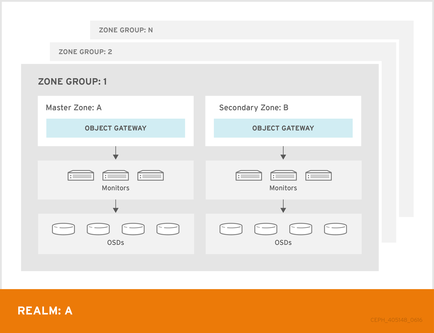
In Red Hat Ceph Storage 2, multi site configurations are active-active by default. When deploying a multi site cluster, the zones and their underlying Ceph storage clusters may be in different geographic regions. Since each zone has a deep copy of each object in the same namespace, users can access the copy from the zone that is physically the closest to them, reducing latency. However, the cluster may be configured in active-passive mode if the secondary zones are intended only for failover and disaster recovery.
Using a zone group with multiple zones is supported. Using multiple zone groups is a technology preview only, and is not supported in production.
7.4. Creating Service Pools
The Ceph Object Gateway uses many pools for various service functions, and a separate set of placement pools for storing bucket indexes, data and other information.
Since it is computationally expensive to peer a pool’s placement groups, Red Hat generally recommends that the Ceph Object Gateway’s service pools use substantially fewer placement groups than data storage pools.
The service pools store objects related to service control, garbage collection, logging, user information, usage, etc. By convention, these pool names have the zone name prepended to the pool name.
Since Red Hat Ceph Storage 4.1, garbage collection uses the log pool with regular RADOS objects instead of OMAP. In the future, more features will store metadata on the log pool. Therefore, it is highly recommended to use NVMe/SSD OSDs for the log pool.
-
.<zone-name>.rgw.control: The control pool. -
.<zone-name>.log: The log pool contains logs of all bucket/container and object actions such as create, read, update and delete. -
.<zone-name>.rgw.buckets.index: This pool stores index of the buckes. -
.<zone-name>.rgw.buckets.data: This pool stores data of the buckets. -
.<zone-name>.rgw.meta: The metadata pool storesuser_keysand other critical metadata. -
.<zone-name>.meta:users.uid: The user ID pool contains a map of unique user IDs. -
.<zone-name>.meta:users.keys: The keys pool contains access keys and secret keys for each user ID. -
.<zone-name>.meta:users.email: The email pool contains email addresses associated to a user ID. -
.<zone-name>.meta:users.swift: The Swift pool contains the Swift subuser information for a user ID.
Execute the Get a Zone procedure to see the pool names.
# radosgw-admin zone get [--rgw-zone=<zone>]
When radosgw-admin creates a zone, the pool names SHOULD be prepended with the zone name. For example, a zone named us-west SHOULD have pool names that look something like this:
{ "domain_root": ".rgw.root",
  "control_pool": ".us-west.rgw.control",
  "gc_pool": ".us-west.rgw.gc",
  "log_pool": ".us-west.log",
  "intent_log_pool": ".us-west.intent-log",
  "usage_log_pool": ".us-west.usage",
  "user_keys_pool": ".us-west.users.keys",
  "user_email_pool": ".us-west.users.email",
  "user_swift_pool": ".us-west.users.swift",
  "user_uid_pool": ".us-west.users.uid",
  "system_key": { "access_key": "", "secret_key": ""},
  "placement_pools": [
    {  "key": "default-placement",
       "val": { "index_pool": ".us-west.rgw.buckets.index",
                "data_pool": ".us-west.rgw.buckets",
                "data_extra_pool": ".us-west.rgw.buckets.non-ec"
                "index_type": 0
              }
    }
  ]
}
Beginning with control_pool and ending with user_uid_pool, create the pools using the pool names in the zone, provided the zone name is prepended to the pool name. Following the previous examples, pool creation might look something like this:
# ceph osd pool create .us-west.rgw.control 32 32 replicated rgw-service
...
# ceph osd pool create .us-west.users.uid 32 32 replicated rgw-service
From previous examples, the rgw-service rule represents a CRUSH hierarchy of SAS drives with SSD journals and rack as the CRUSH failure domain. See Creating CRUSH Roots, and Creating CRUSH Rules for preceding examples.
See the Ceph Placement Groups (PGs) per Pool Calculator and the Placement Groups chapter in the Storage Strategies guide for details on the number of PGs. See the Create a Pool section in the Storage Strategies guide for details on creating a pool.
For service pools the suggested PG count from the calculator is substantially less than the target PGs per OSD. Ensure that step 3 of the calculator specifies the correct number of OSDs.
Generally, the .rgw.root pool and the service pools should use the same CRUSH hierarchy and use at least node as the failure domain in the CRUSH rule. Like the .rgw.root pool, the service pools should use replicated for data durability, NOT erasure.
7.5. Creating Data Placement Strategies
The Ceph Object Gateway has a default storage policy called default-placement. If the cluster has only one storage policy, the default-placement policy will suffice. This default placement policy is referenced from the zone group configuration and defined in the zone configuration.
See Storage Policies section in the Red Hat Ceph Storage 4 Ceph Object Gateway Guide for Red Hat Enterprise Linux for additional details.
For clusters that support multiple use cases, such as IOPS-optimized, throughput-optimized or capacity-optimized, a set of placement targets in the zone group configuration and a set of placement pools in the zone configuration represent each storage policy.
The examples in the following sections illustrate how to create a storage policy and make it the default policy. This example also assumes the default policy will use a throughput-optimized hardware profile. Topics include:
7.5.1. Creating an Index Pool
By default, Ceph Object Gateway maps a bucket’s objects to an index, which enables a gateway client to request a list of objects in a bucket among other things. While common use cases may involve quotas where users have a bucket and a limited number of objects per bucket, buckets can store innumerable objects. When buckets store millions of objects or more, index performance benefits substantially from using high performance storage media such as SSD or NVMe drives to store its data. Additionally, bucket sharding also dramatically improves performance.
See the Ceph Placement Groups (PGs) per Pool Calculator and the Placement Groups chapter in the Storage Strategies guide for details on the number of PGs. See the Create a Pool section in the Storage Strategies guide for details on creating a pool.
The PG per Pool Calculator recommends a smaller number of PGs per pool for the index pool; however, the PG count is approximately twice the number of PGs as the service pools.
Red Hat does not support HDD devices for index pools. For more information on supported configurations, see the Red Hat Ceph Storage: Supported configurations article.
To create an index pool, execute ceph osd pool create with the pool name, the number of PGs and PGPs, the replicated data durability method, and the name of the rule.
If buckets will store more than 100k objects, configure bucket sharding to ensure that index performance doesn’t degrade as the number of objects in the bucket increases. See the Configuring Bucket Sharding section in the Ceph Object Gateway Guide Configuration and Administration Guide. Also see the Bucket Index Resharding section in the Ceph Object Gateway Guide Configuration and Administration Guide for details on resharding a bucket if the original configuration is no longer suitable.
7.5.2. Creating a Data Pool
The data pool is where Ceph Object Gateway stores the object data for a particular storage policy. The data pool should have a full complement of PGs, not the reduced number of PGs for service pools. The data pool SHOULD consider using erasure coding, as it is substantially more efficient than replication and can significantly reduce the capacity requirements while maintaining data durability.
To use erasure coding, create an erasure code profile. See the Erasure Code Profiles section in the Storage Strategies Guide for more details.
Choosing the correct profile is important because you cannot change the profile after you create the pool. To modify a profile, you must create a new pool with a different profile and migrate the objects from the old pool to the new pool.
The default configuration is two data chunks and one encoding chunk, which means only one OSD can be lost. For higher resiliency, consider a larger number of data and encoding chunks. For example, some large very scale systems use 8 data chunks and 3 encoding chunks, which allows three OSDs to fail without losing data.
Each data and encoding chunk SHOULD get stored on a different node or host at a minimum. For smaller clusters, this makes using rack impractical as the minimum CRUSH failure domain when using a larger number of data and encoding chunks. Consequently, it is common for the data pool to use a separate CRUSH hierarchy with host as the minimum CRUSH failure domain. Red Hat recommends host as the minimum failure domain. If erasure code chunks get stored on OSDs within the same host, a host failure such as a failed journal or network card could lead to data loss.
To create a data pool, execute ceph osd pool create with the pool name, the number of PGs and PGPs, the erasure data durability method, the erasure code profile and the name of the rule.
7.5.3. Creating a Data Extra Pool
The data_extra_pool is for data that cannot use erasure coding. For example, multi-part uploads allow uploading a large object such as a movie in multiple parts. These parts must first be stored without erasure coding. Erasure coding will apply to the whole object, not the partial uploads.
The PG per Pool Calculator recommends a smaller number of PGs per pool for the data_extra_pool; however, the PG count is approximately twice the number of PGs as the service pools and the same as the bucket index pool.
To create a data extra pool, execute ceph osd pool create with the pool name, the number of PGs and PGPs, the replicated data durability method, and the name of the rule. For example:
# ceph osd pool create .us-west.rgw.buckets.non-ec 64 64 replicated rgw-service
7.5.4. Configuring Placement Targets in a Zone Group
Once the pools are created, create the placement target in the zone group. To retrieve the zone group, execute the following to output the zone group configuration to a file called zonegroup.json:
# radosgw-admin zonegroup get [--rgw-zonegroup=<zonegroup>] > zonegroup.json
The file contents will look something like this:
{
  "id": "90b28698-e7c3-462c-a42d-4aa780d24eda",
  "name": "us",
  "api_name": "us",
  "is_master": "true",
  "endpoints": [
    "http:\/\/rgw1:80"
  ],
  "hostnames": [],
  "hostnames_s3website": [],
  "master_zone": "9248cab2-afe7-43d8-a661-a40bf316665e",
  "zones": [
      {
        "id": "9248cab2-afe7-43d8-a661-a40bf316665e",
        "name": "us-east",
        "endpoints": [
            "http:\/\/rgw1"
        ],
        "log_meta": "true",
        "log_data": "true",
        "bucket_index_max_shards": 0,
        "read_only": "false"
      },
      {
        "id": "d1024e59-7d28-49d1-8222-af101965a939",
        "name": "us-west",
        "endpoints": [
            "http:\/\/rgw2:80"
        ],
        "log_meta": "false",
        "log_data": "true",
        "bucket_index_max_shards": 0,
        "read_only": "false"
      }
  ],
  "placement_targets": [
      {
        "name": "default-placement",
        "tags": []
      }
  ],
  "default_placement": "default-placement",
  "realm_id": "ae031368-8715-4e27-9a99-0c9468852cfe"
}
The placement_targets section will list each storage policy. By default, it will contain a placement target called default-placement. The default placement target is identified immediately after the placement_targets section.
Assuming a placement target called throughput-optimized, with throughput-optimized as the default target, the placement_targets section and the default_placement setting of the zone group configuration should be modified to something like this:
{
  ...
  "placement_targets": [
      {
        "name": "throughput-optimized",
        "tags": []
      }
  ],
  "default_placement": "throughput-optimized",
  ...
}
Finally, set the zone group configuration with the settings from the modified zonegroup.json file; then, update the period. For example:
# radosgw-admin zonegroup set [--rgw-zonegroup=<zonegroup>] --infile zonegroup.json
# radosgw-admin period update --commit
7.5.5. Configuring Placement Pools in a Zone
Once the zone group has the new throughput-optimized placement target, map the placement pools for throughput-optimized in the zone configuration. This step will replace the mapping for default-placement to its associated pools with a throughput-optimized set of placement pools.
Execute the Get a Zone procedure to see the pool names.
# radosgw-admin zone get [--rgw-zone=<zone>] > zone.json
Assuming a zone named us-west, the file contents will look something like this:
{ "domain_root": ".rgw.root",
  "control_pool": ".us-west.rgw.control",
  "gc_pool": ".us-west.rgw.gc",
  "log_pool": ".us-west.log",
  "intent_log_pool": ".us-west.intent-log",
  "usage_log_pool": ".us-west.usage",
  "user_keys_pool": ".us-west.users.keys",
  "user_email_pool": ".us-west.users.email",
  "user_swift_pool": ".us-west.users.swift",
  "user_uid_pool": ".us-west.users.uid",
  "system_key": { "access_key": "", "secret_key": ""},
  "placement_pools": [
    {  "key": "default-placement",
       "val": { "index_pool": ".us-west.rgw.buckets.index",
                "data_pool": ".us-west.rgw.buckets",
                "data_extra_pool": ".us-west.rgw.buckets.non-ec"
                "index_type": 0
              }
    }
  ]
}
The placement_pools section of the zone configuration defines sets of placement pools. Each set of placement pools defines a storage policy. Modify the file to remove the default-placement entry, and replace it with a throughput-optimized entry with the pools created in the preceding steps. For example:
{
...
"placement_pools": [
    {  "key": "throughput-optimized",
       "val": { "index_pool": ".us-west.rgw.buckets.index",
                "data_pool": ".us-west.rgw.buckets.throughput"}
                "data_extra_pool": ".us-west.rgw.buckets.non-ec",
                "index_type": 0
    }
  ]
}
Finally, set the zone configuration with the settings from the modified zone.json file; then, update the period. For example:
# radosgw-admin zone set --rgw-zone={zone-name} --infile zone.json
# radosgw-admin period update --commit
The index_pool points to the index pool and CRUSH hierarchy with SSDs or other high-performance storage, the data_pool points to a pool with a full complement of PGs, and a CRUSH hierarchy of high-throughput host bus adapters, SAS drives and SSDs for journals.
7.5.6. Data Placement Summary
When processing client requests, the Ceph Object Gateway will use the new throughput-optimized target as the default storage policy. Use this procedure to establish the same target in different zones and zone groups in a multi-site configuration, replacing the zone name for the pools as appropriate.
Use this procedure to establish additional storage policies. The naming for each target and set of placement pools is arbitrary. It could be fast, streaming, cold-storage or any other suitable name. However, each set must have a corresponding entry under placement_targets in the zone group, and one of the targets MUST be referenced in the default_placement setting; and, the zone must have a corresponding set of pools configured for each policy.
Client requests will always use the default target, unless the client request specifies X-Storage-Policy and a different target. See Create a Container for an object gateway client usage example.
Chapter 8. Configuring Gateways
The final steps in preparing the Ceph Object Gateway for production involve configuring Civetweb, firewall ports, the DNS and load balancers. Topics include:
8.1. Configuring Civetweb
Depending on the choices made during installation of the Ceph Object Gateway, the Ceph configuration file will already have entries for each instance of the Ceph Object Gateway with additional modifications from the steps involved in Creating a Realm.
The most common configuration change from the default configuration is changing the default Ansible configured port of 8080 to another port such as 80. See Changing the CivetWeb port.
There are additional settings particular to Civetweb. See Civetweb Configuration Options for details.
There are additional settings which may be overridden. See Object Gateway Configuration Reference for details.
The section on Additional Use Cases will provide detailed configuration examples for using Ceph Object Gateway with third party components.
8.2. Configuring Firewall Ports
When changing the default port for Civetweb, ensure that the corresponding ports are open for client access. For details, see the Configuring the Firewall for Red Hat Ceph Storage section in the Red Hat Ceph Storage 4 Installation Guide for Red Hat Enterprise Linux.
8.3. Configuring DNS Wildcards
S3-style subdomains incorporate the bucket name as a CNAME extension. Add a wildcard to the DNS to facilitate S3-style subdomains. For details, see the Adding a Wildcard to DNS section in the Red Hat Ceph Storage 4 Ceph Object Gateway Guide Configuration and Administration Guide.
8.4. Configuring Load Balancers
A zone will typically have multiple instances of a Ceph Object Gateway to handle production loads and to maintain high availability. Production clusters typically use a load balancer to allocate requests among gateway instances.
Additionally, earlier versions of Civetweb do not support HTTPS. A load balancer can be configured to accept SSL requests, terminate the SSL connection and pass the request over HTTP to the gateway instances.
Ceph Storage aims to maintain high availability. For this reason, Red Hat recommends using HAProxy or keepalived. For details, see the HAProxy/keepalived Configuration section in the Ceph Object Gateway Guide Configuration and Administration Guide.
8.5. Using the Beast front end
The Ceph Object Gateway provides CivetWeb and Beast embedded HTTP servers as front ends. The Beast front end uses the Boost.Beast library for HTTP parsing and the Boost.Asio library for asynchronous network I/O. In Red Hat Ceph Storage version 3.x, CivetWeb was the default front end, and to use the Beast front end it needed to be specified with rgw_frontends in the Red Hat Ceph Storage configuration file. As of Red Hat Ceph Storage version 4.0, the Beast front end is default, and upgrading from Red Hat Ceph Storage 3.x automatically changes the rgw_frontends parameter to Beast.
Additional Resources
8.6. Beast configuration options
The following Beast configuration options can be passed to the embedded web server in the Ceph configuration file for the RADOS Gateway. Each option has a default value. If a value is not specified, the default value is empty.
| Option | Description | Default |
|---|---|---|
|
|
Sets the listening address in the form | EMPTY |
|
| Path to the SSL certificate file used for SSL-enabled endpoints. If the file is a PEM file containing more than one item the order is important. The file must begin with the RGW server key, then any intermediate certificate, and finally the CA certificate. | EMPTY |
|
|
Optional path to the private key file used for SSL-enabled endpoints. If one is not given the file specified by | EMPTY |
|
| Performance optimization in some environments. | EMPTY |
|
| Set an explicit request timeout for the Beast front end. Setting a larger request timeout can make the gateway more tolerant of slow clients (for example, clients connected over high-latency networks). | 65 |
Example /etc/ceph/ceph.conf file with Beast options using SSL:
...

[client.rgw.node1]
rgw frontends = beast ssl_endpoint=192.168.0.100:443 ssl_certificate=<path to SSL certificate>
By default, the Beast front end writes an access log line recording all requests processed by the server to the RADOS Gateway log file.
Additional Resources
- See Using the Beast front end for more information.
Chapter 9. Additional Use Cases
Once the cluster is up and running, there are additional use cases to consider.
9.1. Expanding the Cluster with Multisite
When developing storage strategies, the procedure for Creating a Realm ensured that the cluster is already configured to use multi-site with its own realm, master zone group and master zone.
A typical production cluster will have a secondary zone with its own Ceph Storage Cluster in a separate physical location to act as a backup in the event of a disaster. To set up a secondary zone, repeat the procedures in this guide. Generally, the secondary zone should have the same hardware configuration and sizing as the master zone. See Configuring a Secondary Zone for additional details.
Adding a secondary zone adds Failover and Disaster Recovery capabilities to the cluster.
9.2. Migrating Data with NFS Ganesha
If the Ceph Object Gateway and Ceph Storage Cluster replaces a file system-based storage solution, consider using Ceph’s NFS-Ganesha solution to migrate data from the file system into Ceph Object Gateway.
See Exporting the Namespace to NFS-Ganesha chapter in the Ceph Object Gateway Configuration and Administration Guide.
9.3. Configuring the Cluster for Static Webhosting
Traditional web hosting sometimes involves setting up a web server for each website, which can use resources inefficiently when content does not change dynamically.
Ceph Object Gateway can host static web sites in S3 buckets—that is, sites that do not use server-side services like PHP, servlets, databases, nodejs and the like. This approach is substantially more economical than setting up VMs with web servers for each site.
See Configuring Gateways for Static Web Hosting for additional details.
9.4. Configuring the Cluster for LDAP/AD
Organizations deploying Ceph Object Gateway for their users and applications may choose to use Light-weight Directory Access Protocol (LDAP) or Microsoft Active Directory (AD) to authenticate with the Ceph Object Gateway in lieu of creating Ceph Object Gateway users.
Using LDAP/AD means that Ceph Object Gateway can integrate with an organizations LDAP/AD single sign-on initiatives.
For details, see the Ceph Object Gateway with LDAP/AD Guide for Red Hat Ceph Storage 4.
9.5. Configuring the Cluster to use OpenStack Keystone
When deploying the Ceph Object Gateway in lieu of OpenStack Swift, it is possible to configure the gateway to use OpenStack Keystone to authenticate users in lieu of creating Ceph Object Gateway users.
For details, see the Using Keystone to Authenticate Ceph Object Gateway Users guide for Red Hat Ceph Storage 4.
Chapter 10. Using NVMe with LVM Optimally
Summary
The procedures below demonstrate how to deploy Ceph for Object Gateway usage optimally when using high speed NVMe based SSDs (this applies to SATA SSDs too). Journals and bucket indexes will be placed together on high speed storage devices, which can increase performance compared to having all journals on one device. This configuration requires setting
osd_scenariotolvm.Procedures for two example configurations are provided:
- One NVMe device and at least four HDDs using one bucket index: One NVMe device
- Two NVMe devices and at least four HDDs using two bucket indexes: Two NVMe devices
Details
The most basic Ceph setup uses the
osd_scenariosetting ofcollocated. This stores the OSD data and its journal on one storage device together (they are "co-located"). Typical server configurations include both HDDs and SSDs. Since HDDs are usually larger than SSDs, in a collocated configuration to utitlize the most storage space an HDD would be chosen, putting both the OSD data and journal on it alone. However, the journal should ideally be on a faster SSD. Another option is using theosd_scenariosetting ofnon-collocated. This allows configuration of dedicated devices for journals, so you can put the OSD data on HDDs and the journals on SSDs.In addition to OSD data and journals, when using Object Gateway a bucket index needs to be stored on a device. In this case Ceph is often configured so that HDDs hold the OSD data, one SSD holds the journals, and another SSD holds the bucket indexes. This can create highly imbalanced situations where the SSD with all the journals becomes saturated while the SSD with bucket indexes is underutilized.
The solution is to set
osd_scenariotolvmand use Logical Volume Manager (LVM) to divide up single SSD devices for more than one purpose. This allows journals and bucket indexes to exist side by side on a single device. Most importantly, it allows journals to exist on more than one SSD, spreading the intense IO data transfer of the journals across more than one device.The normal Ansible playbooks provided by the
ceph-ansibleRPM used to install Ceph (site.yml, osds.yml, etc.) don’t support using one device for more than one purpose.In the future the normal Ansible playbooks will support using one device for more than one purpose. In the meantime the playbooks
lv-create.ymlandlv-vars.yamlare being provided to facilitate creating the required Logicial Volumes (LVs) for optimal SSD usage. Afterlv-create.ymlis runsite.ymlcan be run normally and it will use the newly created LVs.ImportantThese procedures only apply to the FileStore storage backend, not the newer BlueStore storage backend.
10.1. Using One NVMe Device
Follow this procedure to deploy Ceph for Object Gateway usage with one NVMe device.
10.1.1. Purge Any Existing Ceph Cluster
If Ceph is already configured, purge it in order to start over. The Ansible playbook, purge-cluster.yml, is provided for this purpose.
$ ansible-playbook infrastructure-playbooks/purge-cluster.yml -i hosts
For more information on how to use purge-cluster.yml see Purging a Ceph Cluster by Using Ansible in the Installation Guide.
Purging the cluster may not be enough to prepare the servers for redeploying Ceph using the following procedures. Any file system, GPT, RAID, or other signatures on storage devices used by Ceph may cause problems. Instructions to remove any signatures using wipefs are provided under Run The lv-create.yml Ansible Playbook.
10.1.2. Configure The Cluster for Normal Installation
Setting aside any NVMe and/or LVM considerations, configure the cluster as you would normally but stop before running the Ansible playbook. Afterwards, the cluster installation configuration will be adjusted specifically for optimal NVMe/LVM usage to support the Object Gateway. Only at that time should the Ansible playbook be ran.
To configure the storage cluster for normal installation consult the Red Hat Ceph Storage Installation Guide. In particular, complete the steps in Installing a Red Hat Ceph Storage Cluster through Step 9 creating an Ansible log directory. Stop before Step 10, when ansible-playbook site.yml -i hosts is ran.
Do not run ansible-playbook site.yml -i hosts until all the steps after this and before Install Ceph for NVMe and Verify Success have been completed.
10.1.3. Identify The NVMe and HDD Devices
Use lsblk to identify the NVMe and HDD devices connected to the server. Example output from lsblk is listed below:
[root@c04-h05-6048r ~]# lsblk
NAME    MAJ:MIN RM   SIZE RO TYPE  MOUNTPOINT
sda       8:0    0 465.8G  0 disk
├─sda1    8:1    0     4G  0 part
│ └─md1   9:1    0     4G  0 raid1 [SWAP]
├─sda2    8:2    0   512M  0 part
│ └─md0   9:0    0   512M  0 raid1 /boot
└─sda3    8:3    0 461.3G  0 part
  └─md2   9:2    0 461.1G  0 raid1 /
sdb       8:16   0 465.8G  0 disk
├─sdb1    8:17   0     4G  0 part
│ └─md1   9:1    0     4G  0 raid1 [SWAP]
├─sdb2    8:18   0   512M  0 part
│ └─md0   9:0    0   512M  0 raid1 /boot
└─sdb3    8:19   0 461.3G  0 part
  └─md2   9:2    0 461.1G  0 raid1 /
sdc       8:32   0   1.8T  0 disk
sdd       8:48   0   1.8T  0 disk
sde       8:64   0   1.8T  0 disk
sdf       8:80   0   1.8T  0 disk
sdg       8:96   0   1.8T  0 disk
sdh       8:112  0   1.8T  0 disk
sdi       8:128  0   1.8T  0 disk
sdj       8:144  0   1.8T  0 disk
sdk       8:160  0   1.8T  0 disk
sdl       8:176  0   1.8T  0 disk
sdm       8:192  0   1.8T  0 disk
sdn       8:208  0   1.8T  0 disk
sdo       8:224  0   1.8T  0 disk
sdp       8:240  0   1.8T  0 disk
sdq      65:0    0   1.8T  0 disk
sdr      65:16   0   1.8T  0 disk
sds      65:32   0   1.8T  0 disk
sdt      65:48   0   1.8T  0 disk
sdu      65:64   0   1.8T  0 disk
sdv      65:80   0   1.8T  0 disk
sdw      65:96   0   1.8T  0 disk
sdx      65:112  0   1.8T  0 disk
sdy      65:128  0   1.8T  0 disk
sdz      65:144  0   1.8T  0 disk
sdaa     65:160  0   1.8T  0 disk
sdab     65:176  0   1.8T  0 disk
sdac     65:192  0   1.8T  0 disk
sdad     65:208  0   1.8T  0 disk
sdae     65:224  0   1.8T  0 disk
sdaf     65:240  0   1.8T  0 disk
sdag     66:0    0   1.8T  0 disk
sdah     66:16   0   1.8T  0 disk
sdai     66:32   0   1.8T  0 disk
sdaj     66:48   0   1.8T  0 disk
sdak     66:64   0   1.8T  0 disk
sdal     66:80   0   1.8T  0 disk
nvme0n1 259:0    0 745.2G  0 disk
nvme1n1 259:1    0 745.2G  0 disk
In this example the following raw block devices will be used:
NVMe devices
-
/dev/nvme0n1
HDD devices
-
/dev/sdc -
/dev/sdd -
/dev/sde -
/dev/sdf
The file lv_vars.yaml configures logical volume creation on the chosen devices. It creates journals on NVMe, an NVMe based bucket index, and HDD based OSDs. The actual creation of logical volumes is initiated by lv-create.yml, which reads lv_vars.yaml.
That file should only have one NVMe device referenced in it at a time. For information on using Ceph with two NVMe devices optimally see Using Two NVMe Devices.
10.1.4. Add The Devices to lv_vars.yaml
As
root, navigate to the/usr/share/ceph-ansible/directory:# cd /usr/share/ceph-ansible
Edit the file so it includes the following lines:
nvme_device: /dev/nvme0n1
hdd_devices:
  - /dev/sdc
  - /dev/sdd
  - /dev/sde
  - /dev/sdf
10.1.5. Run The lv-create.yml Ansible Playbook
The purpose of the lv-create.yml playbook is to create logical volumes for the object gateway bucket index, and journals, on a single NVMe. It does this by using osd_scenario=lvm. The lv-create.yml Ansible playbook makes it easier to configure Ceph in this way by automating some of the complex LVM creation and configuration.
Ensure the storage devices are raw
Before running
lv-create.ymlto create the logical volumes on the NVMe devices and HDD devices, ensure there are no file system, GPT, RAID, or other signatures on them.If they are not raw, when you run
lv-create.ymlit might fail with the following error:device /dev/sdc excluded by a filter
Wipe storage device signatures (optional):
If the devices have signatures you can use
wipefsto erase them.An example of using
wipefsto erase the devices is shown below:[root@c04-h01-6048r ~]# wipefs -a /dev/sdc /dev/sdc: 8 bytes were erased at offset 0x00000200 (gpt): 45 46 49 20 50 41 52 54 /dev/sdc: 8 bytes were erased at offset 0x1d19ffffe00 (gpt): 45 46 49 20 50 41 52 54 /dev/sdc: 2 bytes were erased at offset 0x000001fe (PMBR): 55 aa /dev/sdc: calling ioclt to re-read partition table: Success [root@c04-h01-6048r ~]# wipefs -a /dev/sdd /dev/sdd: 8 bytes were erased at offset 0x00000200 (gpt): 45 46 49 20 50 41 52 54 /dev/sdd: 8 bytes were erased at offset 0x1d19ffffe00 (gpt): 45 46 49 20 50 41 52 54 /dev/sdd: 2 bytes were erased at offset 0x000001fe (PMBR): 55 aa /dev/sdd: calling ioclt to re-read partition table: Success [root@c04-h01-6048r ~]# wipefs -a /dev/sde /dev/sde: 8 bytes were erased at offset 0x00000200 (gpt): 45 46 49 20 50 41 52 54 /dev/sde: 8 bytes were erased at offset 0x1d19ffffe00 (gpt): 45 46 49 20 50 41 52 54 /dev/sde: 2 bytes were erased at offset 0x000001fe (PMBR): 55 aa /dev/sde: calling ioclt to re-read partition table: Success [root@c04-h01-6048r ~]# wipefs -a /dev/sdf /dev/sdf: 8 bytes were erased at offset 0x00000200 (gpt): 45 46 49 20 50 41 52 54 /dev/sdf: 8 bytes were erased at offset 0x1d19ffffe00 (gpt): 45 46 49 20 50 41 52 54 /dev/sdf: 2 bytes were erased at offset 0x000001fe (PMBR): 55 aa /dev/sdf: calling ioclt to re-read partition table: Success
Run the
lv-teardown.ymlAnsible playbook:Always run
lv-teardown.ymlbefore runninglv-create.yml:Run the
lv-teardown.ymlAnsible playbook:$ ansible-playbook infrastructure-playbooks/lv-teardown.yml -i hosts
WarningProceed with caution when running the
lv-teardown.ymlAnsible script. It destroys data. Ensure you have backups of any important data.Run the
lv-create.ymlAnsible playbook:$ ansible-playbook infrastructure-playbooks/lv-create.yml -i hosts
-
Once
lv-create.ymlcompletes without error continue to the next section to verify it worked properly.
10.1.6. Verify LVM Configuration
Review
lv-created.log:Once the
lv-create.ymlAnsible playbook completes successfully, configuration information will be written tolv-created.log. Later this information will be copied intogroup_vars/osds.yml. Openlv-created.logand look for information similar to the below example:- data: ceph-bucket-index-1 data_vg: ceph-nvme-vg-nvme0n1 journal: ceph-journal-bucket-index-1-nvme0n1 journal_vg: ceph-nvme-vg-nvme0n1 - data: ceph-hdd-lv-sdc data_vg: ceph-hdd-vg-sdc journal: ceph-journal-sdc journal_vg: ceph-nvme-vg-nvme0n1 - data: ceph-hdd-lv-sdd data_vg: ceph-hdd-vg-sdd journal: ceph-journal-sdd journal_vg: ceph-nvme-vg-nvme0n1 - data: ceph-hdd-lv-sde data_vg: ceph-hdd-vg-sde journal: ceph-journal-sde journal_vg: ceph-nvme-vg-nvme0n1 - data: ceph-hdd-lv-sdf data_vg: ceph-hdd-vg-sdf journal: ceph-journal-sdf journal_vg: ceph-nvme-vg-nvme0n1Review LVM configuration
Based on the example of one NVMe device and four HDDs the following Logical Volumes (LVs) should be created:
One journal LV per HDD placed on NVMe (four LVs on /dev/nvme0n1)
One data LV per HDD placed on each HDD (one LV per HDD)
One journal LV for bucket index placed on NVMe (one LV on /dev/nvme0n1)
One data LV for bucket index placed on NVMe (one LV on /dev/nvme0n1)
The LVs can be seen in
lsblkandlvscanoutput. In the example explained above, there should be ten LVs for Ceph. As a rough sanity check you could count the Ceph LVs to make sure there are at least ten, but ideally you would make sure the appropriate LVs were created on the right storage devices (NVMe vs HDD).Example output from
lsblkis shown below:[root@c04-h01-6048r ~]# lsblk NAME MAJ:MIN RM SIZE RO TYPE MOUNTPOINT sda 8:0 0 465.8G 0 disk ├─sda1 8:1 0 4G 0 part │ └─md1 9:1 0 4G 0 raid1 [SWAP] ├─sda2 8:2 0 512M 0 part │ └─md0 9:0 0 512M 0 raid1 /boot └─sda3 8:3 0 461.3G 0 part └─md2 9:2 0 461.1G 0 raid1 / sdb 8:16 0 465.8G 0 disk ├─sdb1 8:17 0 4G 0 part │ └─md1 9:1 0 4G 0 raid1 [SWAP] ├─sdb2 8:18 0 512M 0 part │ └─md0 9:0 0 512M 0 raid1 /boot └─sdb3 8:19 0 461.3G 0 part └─md2 9:2 0 461.1G 0 raid1 / sdc 8:32 0 1.8T 0 disk └─ceph--hdd--vg--sdc-ceph--hdd--lv--sdc 253:6 0 1.8T 0 lvm sdd 8:48 0 1.8T 0 disk └─ceph--hdd--vg--sdd-ceph--hdd--lv--sdd 253:7 0 1.8T 0 lvm sde 8:64 0 1.8T 0 disk └─ceph--hdd--vg--sde-ceph--hdd--lv--sde 253:8 0 1.8T 0 lvm sdf 8:80 0 1.8T 0 disk └─ceph--hdd--vg--sdf-ceph--hdd--lv--sdf 253:9 0 1.8T 0 lvm sdg 8:96 0 1.8T 0 disk sdh 8:112 0 1.8T 0 disk sdi 8:128 0 1.8T 0 disk sdj 8:144 0 1.8T 0 disk sdk 8:160 0 1.8T 0 disk sdl 8:176 0 1.8T 0 disk sdm 8:192 0 1.8T 0 disk sdn 8:208 0 1.8T 0 disk sdo 8:224 0 1.8T 0 disk sdp 8:240 0 1.8T 0 disk sdq 65:0 0 1.8T 0 disk sdr 65:16 0 1.8T 0 disk sds 65:32 0 1.8T 0 disk sdt 65:48 0 1.8T 0 disk sdu 65:64 0 1.8T 0 disk sdv 65:80 0 1.8T 0 disk sdw 65:96 0 1.8T 0 disk sdx 65:112 0 1.8T 0 disk sdy 65:128 0 1.8T 0 disk sdz 65:144 0 1.8T 0 disk sdaa 65:160 0 1.8T 0 disk sdab 65:176 0 1.8T 0 disk sdac 65:192 0 1.8T 0 disk sdad 65:208 0 1.8T 0 disk sdae 65:224 0 1.8T 0 disk sdaf 65:240 0 1.8T 0 disk sdag 66:0 0 1.8T 0 disk sdah 66:16 0 1.8T 0 disk sdai 66:32 0 1.8T 0 disk sdaj 66:48 0 1.8T 0 disk sdak 66:64 0 1.8T 0 disk sdal 66:80 0 1.8T 0 disk nvme0n1 259:0 0 745.2G 0 disk ├─ceph--nvme--vg--nvme0n1-ceph--journal--bucket--index--1--nvme0n1 253:0 0 5.4G 0 lvm ├─ceph--nvme--vg--nvme0n1-ceph--journal--sdc 253:1 0 5.4G 0 lvm ├─ceph--nvme--vg--nvme0n1-ceph--journal--sdd 253:2 0 5.4G 0 lvm ├─ceph--nvme--vg--nvme0n1-ceph--journal--sde 253:3 0 5.4G 0 lvm ├─ceph--nvme--vg--nvme0n1-ceph--journal--sdf 253:4 0 5.4G 0 lvm └─ceph--nvme--vg--nvme0n1-ceph--bucket--index--1 253:5 0 718.4G 0 lvm nvme1n1 259:1 0 745.2G 0 disk
Example
lvscanoutput is below:[root@c04-h01-6048r ~]# lvscan ACTIVE '/dev/ceph-hdd-vg-sdf/ceph-hdd-lv-sdf' [<1.82 TiB] inherit ACTIVE '/dev/ceph-hdd-vg-sde/ceph-hdd-lv-sde' [<1.82 TiB] inherit ACTIVE '/dev/ceph-hdd-vg-sdd/ceph-hdd-lv-sdd' [<1.82 TiB] inherit ACTIVE '/dev/ceph-nvme-vg-nvme0n1/ceph-journal-bucket-index-1-nvme0n1' [5.37 GiB] inherit ACTIVE '/dev/ceph-nvme-vg-nvme0n1/ceph-journal-sdc' [5.37 GiB] inherit ACTIVE '/dev/ceph-nvme-vg-nvme0n1/ceph-journal-sdd' [5.37 GiB] inherit ACTIVE '/dev/ceph-nvme-vg-nvme0n1/ceph-journal-sde' [5.37 GiB] inherit ACTIVE '/dev/ceph-nvme-vg-nvme0n1/ceph-journal-sdf' [5.37 GiB] inherit ACTIVE '/dev/ceph-nvme-vg-nvme0n1/ceph-bucket-index-1' [<718.36 GiB] inherit ACTIVE '/dev/ceph-hdd-vg-sdc/ceph-hdd-lv-sdc' [<1.82 TiB] inherit
10.1.7. Edit The osds.yml and all.yml Ansible Playbooks
-
Copy the previously mentioned configuration information from
lv-created.logintogroup_vars/osds.ymlunder thelvm_volumes:line. Set
osd_scenario:tolvm:osd_scenario: lvm
Set
osd_objectstore: filestoreinall.ymlandosds.yml.The
osds.ymlfile should look similar to this:# Variables here are applicable to all host groups NOT roles osd_objectstore: filestore osd_scenario: lvm lvm_volumes: - data: ceph-bucket-index-1 data_vg: ceph-nvme-vg-nvme0n1 journal: ceph-journal-bucket-index-1-nvme0n1 journal_vg: ceph-nvme-vg-nvme0n1 - data: ceph-hdd-lv-sdc data_vg: ceph-hdd-vg-sdc journal: ceph-journal-sdc journal_vg: ceph-nvme-vg-nvme0n1 - data: ceph-hdd-lv-sdd data_vg: ceph-hdd-vg-sdd journal: ceph-journal-sdd journal_vg: ceph-nvme-vg-nvme0n1 - data: ceph-hdd-lv-sde data_vg: ceph-hdd-vg-sde journal: ceph-journal-sde journal_vg: ceph-nvme-vg-nvme0n1 - data: ceph-hdd-lv-sdf data_vg: ceph-hdd-vg-sdf journal: ceph-journal-sdf journal_vg: ceph-nvme-vg-nvme0n1
10.1.8. Install Ceph for NVMe and Verify Success
After configuring Ceph for installation to use NVMe with LVM optimally, install it.
Run the
site.ymlAnsible playbook to install Ceph$ ansible-playbook -v site.yml -i hosts
Verify Ceph is running properly after install completes
# ceph -s
# ceph osd tree
Example
ceph -soutput showing Ceph is running properly:# ceph -s cluster: id: 15d31a8c-3152-4fa2-8c4e-809b750924cd health: HEALTH_WARN Reduced data availability: 32 pgs inactive services: mon: 3 daemons, quorum b08-h03-r620,b08-h05-r620,b08-h06-r620 mgr: b08-h03-r620(active), standbys: b08-h05-r620, b08-h06-r620 osd: 35 osds: 35 up, 35 in data: pools: 4 pools, 32 pgs objects: 0 objects, 0 bytes usage: 0 kB used, 0 kB / 0 kB avail pgs: 100.000% pgs unknown 32 unknownExample
ceph osd treeoutput showing Ceph is running properly:[root@c04-h01-6048r ~]# ceph osd tree ID CLASS WEIGHT TYPE NAME STATUS REWEIGHT PRI-AFF -1 55.81212 root default -15 7.97316 host c04-h01-6048r 13 hdd 1.81799 osd.13 up 1.00000 1.00000 20 hdd 1.81799 osd.20 up 1.00000 1.00000 26 hdd 1.81799 osd.26 up 1.00000 1.00000 32 hdd 1.81799 osd.32 up 1.00000 1.00000 6 ssd 0.70119 osd.6 up 1.00000 1.00000 -3 7.97316 host c04-h05-6048r 12 hdd 1.81799 osd.12 up 1.00000 1.00000 17 hdd 1.81799 osd.17 up 1.00000 1.00000 23 hdd 1.81799 osd.23 up 1.00000 1.00000 29 hdd 1.81799 osd.29 up 1.00000 1.00000 2 ssd 0.70119 osd.2 up 1.00000 1.00000 -13 7.97316 host c04-h09-6048r 11 hdd 1.81799 osd.11 up 1.00000 1.00000 16 hdd 1.81799 osd.16 up 1.00000 1.00000 22 hdd 1.81799 osd.22 up 1.00000 1.00000 27 hdd 1.81799 osd.27 up 1.00000 1.00000 4 ssd 0.70119 osd.4 up 1.00000 1.00000 -5 7.97316 host c04-h13-6048r 10 hdd 1.81799 osd.10 up 1.00000 1.00000 15 hdd 1.81799 osd.15 up 1.00000 1.00000 21 hdd 1.81799 osd.21 up 1.00000 1.00000 28 hdd 1.81799 osd.28 up 1.00000 1.00000 1 ssd 0.70119 osd.1 up 1.00000 1.00000 -9 7.97316 host c04-h21-6048r 8 hdd 1.81799 osd.8 up 1.00000 1.00000 18 hdd 1.81799 osd.18 up 1.00000 1.00000 25 hdd 1.81799 osd.25 up 1.00000 1.00000 30 hdd 1.81799 osd.30 up 1.00000 1.00000 5 ssd 0.70119 osd.5 up 1.00000 1.00000 -11 7.97316 host c04-h25-6048r 9 hdd 1.81799 osd.9 up 1.00000 1.00000 14 hdd 1.81799 osd.14 up 1.00000 1.00000 33 hdd 1.81799 osd.33 up 1.00000 1.00000 34 hdd 1.81799 osd.34 up 1.00000 1.00000 0 ssd 0.70119 osd.0 up 1.00000 1.00000 -7 7.97316 host c04-h29-6048r 7 hdd 1.81799 osd.7 up 1.00000 1.00000 19 hdd 1.81799 osd.19 up 1.00000 1.00000 24 hdd 1.81799 osd.24 up 1.00000 1.00000 31 hdd 1.81799 osd.31 up 1.00000 1.00000 3 ssd 0.70119 osd.3 up 1.00000 1.00000
Ceph is now set up to use one NVMe device and LVM optimally for the Ceph Object Gateway.
10.2. Using Two NVMe Devices
Follow this procedure to deploy Ceph for Object Gateway usage with two NVMe devices.
10.2.1. Purge Any Existing Ceph Cluster
If Ceph is already configured, purge it in order to start over. An ansible playbook file named purge-cluster.yml is provided for this purpose.
$ ansible-playbook purge-cluster.yml -i hosts
For more information on how to use purge-cluster.yml see Purging a Ceph Cluster by Using Ansible in the Installation Guide.
Purging the cluster may not be enough to prepare the servers for redeploying Ceph using the following procedures. Any file system, GPT, RAID, or other signatures on storage devices used by Ceph may cause problems. Instructions to remove any signatures using wipefs are provided under Run The lv-create.yml Ansible Playbook.
10.2.2. Configure The Cluster for Normal Installation
Setting aside any NVMe and/or LVM considerations, configure the cluster as you would normally but stop before running Ansible playbook. Afterwards, the cluster installation configuration will be adjusted specifically for optimal NVMe/LVM usage to support the Object Gateway. Only at that time should Ansible playbook be ran.
To configure the cluster for normal installation consult the Installation Guide. In particular, complete the steps in Installing a Red Hat Ceph Storage Cluster through Step 9 creating an Ansible log directory. Stop before Step 10 when ansible-playbook site.yml -i hosts is ran.
Do not run ansible-playbook site.yml -i hosts until all the steps after this and before Install Ceph for NVMe and Verify Success have been completed.
10.2.3. Identify The NVMe and HDD Devices
Use lsblk to identify the NVMe and HDD devices connected to the server. Example output from lsblk is listed below:
[root@c04-h09-6048r ~]# lsblk
NAME                           MAJ:MIN RM   SIZE RO TYPE MOUNTPOINT
sda                              8:0    0 465.8G  0 disk
├─sda1                           8:1    0   512M  0 part /boot
└─sda2                           8:2    0 465.3G  0 part
  ├─vg_c04--h09--6048r-lv_root 253:0    0 464.8G  0 lvm  /
  └─vg_c04--h09--6048r-lv_swap 253:1    0   512M  0 lvm  [SWAP]
sdb                              8:16   0 465.8G  0 disk
sdc                              8:32   0   1.8T  0 disk
sdd                              8:48   0   1.8T  0 disk
sde                              8:64   0   1.8T  0 disk
sdf                              8:80   0   1.8T  0 disk
sdg                              8:96   0   1.8T  0 disk
sdh                              8:112  0   1.8T  0 disk
sdi                              8:128  0   1.8T  0 disk
sdj                              8:144  0   1.8T  0 disk
sdk                              8:160  0   1.8T  0 disk
sdl                              8:176  0   1.8T  0 disk
sdm                              8:192  0   1.8T  0 disk
sdn                              8:208  0   1.8T  0 disk
sdo                              8:224  0   1.8T  0 disk
sdp                              8:240  0   1.8T  0 disk
sdq                             65:0    0   1.8T  0 disk
sdr                             65:16   0   1.8T  0 disk
sds                             65:32   0   1.8T  0 disk
sdt                             65:48   0   1.8T  0 disk
sdu                             65:64   0   1.8T  0 disk
sdv                             65:80   0   1.8T  0 disk
sdw                             65:96   0   1.8T  0 disk
sdx                             65:112  0   1.8T  0 disk
sdy                             65:128  0   1.8T  0 disk
sdz                             65:144  0   1.8T  0 disk
sdaa                            65:160  0   1.8T  0 disk
sdab                            65:176  0   1.8T  0 disk
sdac                            65:192  0   1.8T  0 disk
sdad                            65:208  0   1.8T  0 disk
sdae                            65:224  0   1.8T  0 disk
sdaf                            65:240  0   1.8T  0 disk
sdag                            66:0    0   1.8T  0 disk
sdah                            66:16   0   1.8T  0 disk
sdai                            66:32   0   1.8T  0 disk
sdaj                            66:48   0   1.8T  0 disk
sdak                            66:64   0   1.8T  0 disk
sdal                            66:80   0   1.8T  0 disk
nvme0n1                        259:1    0 745.2G  0 disk
nvme1n1                        259:0    0 745.2G  0 disk
In this example the following raw block devices will be used:
NVMe devices
-
/dev/nvme0n1 -
/dev/nvme1n1
HDD devices
-
/dev/sdc -
/dev/sdd -
/dev/sde -
/dev/sdf
The file lv_vars.yaml configures logical volume creation on the chosen devices. It creates journals on NVMe, an NVMe based bucket index, and HDD based OSDs. The actual creation of logical volumes is initiated by lv-create.yml, which reads lv_vars.yaml.
That file should only have one NVMe device referenced in it at a time. It should also only reference the HDD devices to be associated with that particular NVMe device. For OSDs that contain more than one NVMe device edit lv_vars.yaml for each NVMe and run lv-create.yml repeatedly for each NVMe. This is explained below.
In the example this means lv-create.yml will first be run on /dev/nvme0n1 and then again on /dev/nvme1n1.
10.2.4. Add The Devices to lv_vars.yaml
As
root, navigate to the/usr/share/ceph-ansible/directory:# cd /usr/share/ceph-ansible
As
root, copy thelv_vars.yamlAnsible playbook to the current directory:# cp infrastructure-playbooks/vars/lv_vars.yaml .
For the first run edit the file so it includes the following lines:
nvme_device: /dev/nvme0n1
hdd_devices:
  - /dev/sdc
  - /dev/sdd
The journal size, number of bucket indexes, their sizes and names, and the bucket indexes' journal names can all be adjusted in lv_vars.yaml. See the comments within the file for more information.
10.2.5. Run The lv-create.yml Ansible Playbook
The purpose of the lv-create.yml playbook is to create logical volumes for the object gateway bucket index, and journals, on a single NVMe. It does this by using osd_scenario=lvm as opposed to using osd_scenario=non-collocated. The lv-create.yml Ansible playbook makes it easier to configure Ceph in this way by automating some of the complex LVM creation and configuration.
As
root, copy thelv-create.ymlAnsible playbook to the current directory:# cp infrastructure-playbooks/lv-create.yml .
Ensure the storage devices are raw
Before running
lv-create.ymlto create the logical volumes on the NVMe devices and HDD devices, ensure there are no file system, GPT, RAID, or other signatures on them.If they are not raw, when you run
lv-create.ymlit may fail with the following error:device /dev/sdc excluded by a filter
Wipe storage device signatures (optional)
If the devices have signatures you can use
wipefsto erase them.An example of using
wipefsto erase the devices is shown below:[root@c04-h01-6048r ~]# wipefs -a /dev/sdc /dev/sdc: 8 bytes were erased at offset 0x00000200 (gpt): 45 46 49 20 50 41 52 54 /dev/sdc: 8 bytes were erased at offset 0x1d19ffffe00 (gpt): 45 46 49 20 50 41 52 54 /dev/sdc: 2 bytes were erased at offset 0x000001fe (PMBR): 55 aa /dev/sdc: calling ioclt to re-read partition table: Success [root@c04-h01-6048r ~]# wipefs -a /dev/sdd /dev/sdd: 8 bytes were erased at offset 0x00000200 (gpt): 45 46 49 20 50 41 52 54 /dev/sdd: 8 bytes were erased at offset 0x1d19ffffe00 (gpt): 45 46 49 20 50 41 52 54 /dev/sdd: 2 bytes were erased at offset 0x000001fe (PMBR): 55 aa /dev/sdd: calling ioclt to re-read partition table: Success [root@c04-h01-6048r ~]# wipefs -a /dev/sde /dev/sde: 8 bytes were erased at offset 0x00000200 (gpt): 45 46 49 20 50 41 52 54 /dev/sde: 8 bytes were erased at offset 0x1d19ffffe00 (gpt): 45 46 49 20 50 41 52 54 /dev/sde: 2 bytes were erased at offset 0x000001fe (PMBR): 55 aa /dev/sde: calling ioclt to re-read partition table: Success [root@c04-h01-6048r ~]# wipefs -a /dev/sdf /dev/sdf: 8 bytes were erased at offset 0x00000200 (gpt): 45 46 49 20 50 41 52 54 /dev/sdf: 8 bytes were erased at offset 0x1d19ffffe00 (gpt): 45 46 49 20 50 41 52 54 /dev/sdf: 2 bytes were erased at offset 0x000001fe (PMBR): 55 aa /dev/sdf: calling ioclt to re-read partition table: Success
Run the
lv-teardown.ymlAnsible playbook:Always run
lv-teardown.ymlbefore runninglv-create.yml:As
root, copy thelv-teardown.ymlAnsible playbook to the current directory:# cp infrastructure-playbooks/lv-teardown.yml .
Run the
lv-teardown.ymlAnsible playbook:$ ansible-playbook lv-teardown.yml -i hosts
WarningProceed with caution when running the
lv-teardown.ymlAnsible script. It destroys data. Ensure you have backups of any important data.Run the
lv-create.ymlAnsible playbook:$ ansible-playbook lv-create.yml -i hosts
10.2.6. Copy First NVMe LVM Configuration
Review
lv-created.logOnce the
lv-create.ymlAnsible playbook completes successfully, configuration information will be written tolv-created.log. Openlv-created.logand look for information similar to the below example:- data: ceph-bucket-index-1 data_vg: ceph-nvme-vg-nvme0n1 journal: ceph-journal-bucket-index-1-nvme0n1 journal_vg: ceph-nvme-vg-nvme0n1 - data: ceph-hdd-lv-sdc data_vg: ceph-hdd-vg-sdc journal: ceph-journal-sdc journal_vg: ceph-nvme-vg-nvme0n1 - data: ceph-hdd-lv-sdd data_vg: ceph-hdd-vg-sdd journal: ceph-journal-sdd journal_vg: ceph-nvme-vg-nvme0n1-
Copy this information into
group_vars/osds.ymlunderlvm_volumes:.
10.2.7. Run The lv-create.yml Playbook on NVMe device two
The following instructions are abbreviated steps to set up a second NVMe device. Consult the related steps above for further context if needed.
Modify
lv-vars.yamlto use the second NVMe and associated HDDs.Following the previous example,
lv-vars.yamlwill now have the following devices set:nvme_device: /dev/nvme1n1 hdd_devices: - /dev/sde - /dev/sdf
Run
lv-teardown.yml:$ ansible-playbook lv-teardown.yml -i hosts
Run
lv-create.ymlagain$ ansible-playbook lv-create.yml -i hosts
10.2.8. Copy Second NVMe LVM Configuration
Review
lv-created.logOnce the
lv-create.ymlAnsible playbook completes successfully, configuration information will be written tolv-created.log. Openlv-created.logand look for information similar to the below example:- data: ceph-bucket-index-1 data_vg: ceph-nvme-vg-nvme1n1 journal: ceph-journal-bucket-index-1-nvme1n1 journal_vg: ceph-nvme-vg-nvme1n1 - data: ceph-hdd-lv-sde data_vg: ceph-hdd-vg-sde journal: ceph-journal-sde journal_vg: ceph-nvme-vg-nvme1n1 - data: ceph-hdd-lv-sdf data_vg: ceph-hdd-vg-sdf journal: ceph-journal-sdf journal_vg: ceph-nvme-vg-nvme1n1-
Copy this information into
group_vars/osds.ymlunder the already entered information underlvm_volumes:.
10.2.9. Verify LVM Configuration
Review LVM Configuration
Based on the example of two NVMe device and four HDDs the following Logical Volumes (LVs) should be created:
One journal LV per HDD placed on both NVMe devices (two LVs on /dev/nvme0n1, two on /dev/nvme1n1)
One data LV per HDD placed on each HDD (one LV per HDD)
One journal LV per bucket index placed on NVMe (one LV on /dev/nvme0n1, one LV on /dev/nvme1n1)
One data LV per bucket index placed on both NVMe devices (one LV on /dev/nvme0n1, one LV on /dev/nvme1n1)
The LVs can be seen in
lsblkandlvscanoutput. In the example explained above, there should be twelve LVs for Ceph. As a rough sanity check you could count the Ceph LVs to make sure there are at least twelve, but ideally you would make sure the appropriate LVs were created on the right storage devices (NVMe vs HDD).Example output from
lsblkis shown below:[root@c04-h01-6048r ~]# lsblk NAME MAJ:MIN RM SIZE RO TYPE MOUNTPOINT sda 8:0 0 465.8G 0 disk ├─sda1 8:1 0 4G 0 part │ └─md1 9:1 0 4G 0 raid1 [SWAP] ├─sda2 8:2 0 512M 0 part │ └─md0 9:0 0 512M 0 raid1 /boot └─sda3 8:3 0 461.3G 0 part └─md2 9:2 0 461.1G 0 raid1 / sdb 8:16 0 465.8G 0 disk ├─sdb1 8:17 0 4G 0 part │ └─md1 9:1 0 4G 0 raid1 [SWAP] ├─sdb2 8:18 0 512M 0 part │ └─md0 9:0 0 512M 0 raid1 /boot └─sdb3 8:19 0 461.3G 0 part └─md2 9:2 0 461.1G 0 raid1 / sdc 8:32 0 1.8T 0 disk └─ceph--hdd--vg--sdc-ceph--hdd--lv--sdc 253:4 0 1.8T 0 lvm sdd 8:48 0 1.8T 0 disk └─ceph--hdd--vg--sdd-ceph--hdd--lv--sdd 253:5 0 1.8T 0 lvm sde 8:64 0 1.8T 0 disk └─ceph--hdd--vg--sde-ceph--hdd--lv--sde 253:10 0 1.8T 0 lvm sdf 8:80 0 1.8T 0 disk └─ceph--hdd--vg--sdf-ceph--hdd--lv--sdf 253:11 0 1.8T 0 lvm sdg 8:96 0 1.8T 0 disk sdh 8:112 0 1.8T 0 disk sdi 8:128 0 1.8T 0 disk sdj 8:144 0 1.8T 0 disk sdk 8:160 0 1.8T 0 disk sdl 8:176 0 1.8T 0 disk sdm 8:192 0 1.8T 0 disk sdn 8:208 0 1.8T 0 disk sdo 8:224 0 1.8T 0 disk sdp 8:240 0 1.8T 0 disk sdq 65:0 0 1.8T 0 disk sdr 65:16 0 1.8T 0 disk sds 65:32 0 1.8T 0 disk sdt 65:48 0 1.8T 0 disk sdu 65:64 0 1.8T 0 disk sdv 65:80 0 1.8T 0 disk sdw 65:96 0 1.8T 0 disk sdx 65:112 0 1.8T 0 disk sdy 65:128 0 1.8T 0 disk sdz 65:144 0 1.8T 0 disk sdaa 65:160 0 1.8T 0 disk sdab 65:176 0 1.8T 0 disk sdac 65:192 0 1.8T 0 disk sdad 65:208 0 1.8T 0 disk sdae 65:224 0 1.8T 0 disk sdaf 65:240 0 1.8T 0 disk sdag 66:0 0 1.8T 0 disk sdah 66:16 0 1.8T 0 disk sdai 66:32 0 1.8T 0 disk sdaj 66:48 0 1.8T 0 disk sdak 66:64 0 1.8T 0 disk sdal 66:80 0 1.8T 0 disk nvme0n1 259:0 0 745.2G 0 disk ├─ceph--nvme--vg--nvme0n1-ceph--journal--bucket--index--1--nvme0n1 253:0 0 5.4G 0 lvm ├─ceph--nvme--vg--nvme0n1-ceph--journal--sdc 253:1 0 5.4G 0 lvm ├─ceph--nvme--vg--nvme0n1-ceph--journal--sdd 253:2 0 5.4G 0 lvm └─ceph--nvme--vg--nvme0n1-ceph--bucket--index--1 253:3 0 729.1G 0 lvm nvme1n1 259:1 0 745.2G 0 disk ├─ceph--nvme--vg--nvme1n1-ceph--journal--bucket--index--1--nvme1n1 253:6 0 5.4G 0 lvm ├─ceph--nvme--vg--nvme1n1-ceph--journal--sde 253:7 0 5.4G 0 lvm ├─ceph--nvme--vg--nvme1n1-ceph--journal--sdf 253:8 0 5.4G 0 lvm └─ceph--nvme--vg--nvme1n1-ceph--bucket--index--1 253:9 0 729.1G 0 lvm
Example output from
lvscanis shown below:[root@c04-h01-6048r ~]# lvscan ACTIVE '/dev/ceph-hdd-vg-sde/ceph-hdd-lv-sde' [<1.82 TiB] inherit ACTIVE '/dev/ceph-hdd-vg-sdc/ceph-hdd-lv-sdc' [<1.82 TiB] inherit ACTIVE '/dev/ceph-hdd-vg-sdf/ceph-hdd-lv-sdf' [<1.82 TiB] inherit ACTIVE '/dev/ceph-nvme-vg-nvme1n1/ceph-journal-bucket-index-1-nvme1n1' [5.37 GiB] inherit ACTIVE '/dev/ceph-nvme-vg-nvme1n1/ceph-journal-sde' [5.37 GiB] inherit ACTIVE '/dev/ceph-nvme-vg-nvme1n1/ceph-journal-sdf' [5.37 GiB] inherit ACTIVE '/dev/ceph-nvme-vg-nvme1n1/ceph-bucket-index-1' [<729.10 GiB] inherit ACTIVE '/dev/ceph-nvme-vg-nvme0n1/ceph-journal-bucket-index-1-nvme0n1' [5.37 GiB] inherit ACTIVE '/dev/ceph-nvme-vg-nvme0n1/ceph-journal-sdc' [5.37 GiB] inherit ACTIVE '/dev/ceph-nvme-vg-nvme0n1/ceph-journal-sdd' [5.37 GiB] inherit ACTIVE '/dev/ceph-nvme-vg-nvme0n1/ceph-bucket-index-1' [<729.10 GiB] inherit ACTIVE '/dev/ceph-hdd-vg-sdd/ceph-hdd-lv-sdd' [<1.82 TiB] inherit
10.2.10. Edit The osds.yml and all.yml Ansible Playbooks
Set
osd_objectstoretobluestoreIn addition to adding the second set of information from
lv-create.logintoosds.yml,osd_objectstorealso needs to be set tobluestorein both theosds.ymlandall.ymlfiles.The line should look like this in both
osds.ymlandall.yml:osd_objectstore: bluestore
Set
osd_scenariotolvminosds.ymlThe
osds.ymlfile should look similar to the following example:# Variables here are applicable to all host groups NOT roles osd_objectstore: bluestore osd_scenario: lvm lvm_volumes: - data: ceph-bucket-index-1 data_vg: ceph-nvme-vg-nvme0n1 journal: ceph-journal-bucket-index-1-nvme0n1 journal_vg: ceph-nvme-vg-nvme0n1 - data: ceph-hdd-lv-sdc data_vg: ceph-hdd-vg-sdc journal: ceph-journal-sdc journal_vg: ceph-nvme-vg-nvme0n1 - data: ceph-hdd-lv-sdd data_vg: ceph-hdd-vg-sdd journal: ceph-journal-sdd journal_vg: ceph-nvme-vg-nvme0n1 - data: ceph-bucket-index-1 data_vg: ceph-nvme-vg-nvme1n1 journal: ceph-journal-bucket-index-1-nvme1n1 journal_vg: ceph-nvme-vg-nvme1n1 - data: ceph-hdd-lv-sde data_vg: ceph-hdd-vg-sde journal: ceph-journal-sde journal_vg: ceph-nvme-vg-nvme1n1 - data: ceph-hdd-lv-sdf data_vg: ceph-hdd-vg-sdf journal: ceph-journal-sdf journal_vg: ceph-nvme-vg-nvme1n1
10.2.11. Install Ceph for NVMe and Verify Success
Run the
site.ymlAnsible playbook to install Ceph$ ansible-playbook -v site.yml -i hosts
Verify Ceph is running properly after install completes
# ceph -s
# ceph osd tree
Example
ceph -soutput showing Ceph is running properly:# ceph -s cluster: id: 9ba22f4c-b53f-4c49-8c72-220aaf567c2b health: HEALTH_WARN Reduced data availability: 32 pgs inactive services: mon: 3 daemons, quorum b08-h03-r620,b08-h05-r620,b08-h06-r620 mgr: b08-h03-r620(active), standbys: b08-h05-r620, b08-h06-r620 osd: 42 osds: 42 up, 42 in data: pools: 4 pools, 32 pgs objects: 0 objects, 0 bytes usage: 0 kB used, 0 kB / 0 kB avail pgs: 100.000% pgs unknown 32 unknownExample
ceph osd treeoutput showing Ceph is running properly:[root@c04-h01-6048r ~]# ceph osd tree ID CLASS WEIGHT TYPE NAME STATUS REWEIGHT PRI-AFF -1 60.86740 root default -7 8.69534 host c04-h01-6048r 10 hdd 1.81799 osd.10 up 1.00000 1.00000 13 hdd 1.81799 osd.13 up 1.00000 1.00000 21 hdd 1.81799 osd.21 up 1.00000 1.00000 27 hdd 1.81799 osd.27 up 1.00000 1.00000 6 ssd 0.71169 osd.6 up 1.00000 1.00000 15 ssd 0.71169 osd.15 up 1.00000 1.00000 -3 8.69534 host c04-h05-6048r 7 hdd 1.81799 osd.7 up 1.00000 1.00000 20 hdd 1.81799 osd.20 up 1.00000 1.00000 29 hdd 1.81799 osd.29 up 1.00000 1.00000 38 hdd 1.81799 osd.38 up 1.00000 1.00000 4 ssd 0.71169 osd.4 up 1.00000 1.00000 25 ssd 0.71169 osd.25 up 1.00000 1.00000 -22 8.69534 host c04-h09-6048r 17 hdd 1.81799 osd.17 up 1.00000 1.00000 31 hdd 1.81799 osd.31 up 1.00000 1.00000 35 hdd 1.81799 osd.35 up 1.00000 1.00000 39 hdd 1.81799 osd.39 up 1.00000 1.00000 5 ssd 0.71169 osd.5 up 1.00000 1.00000 34 ssd 0.71169 osd.34 up 1.00000 1.00000 -9 8.69534 host c04-h13-6048r 8 hdd 1.81799 osd.8 up 1.00000 1.00000 11 hdd 1.81799 osd.11 up 1.00000 1.00000 30 hdd 1.81799 osd.30 up 1.00000 1.00000 32 hdd 1.81799 osd.32 up 1.00000 1.00000 0 ssd 0.71169 osd.0 up 1.00000 1.00000 26 ssd 0.71169 osd.26 up 1.00000 1.00000 -19 8.69534 host c04-h21-6048r 18 hdd 1.81799 osd.18 up 1.00000 1.00000 23 hdd 1.81799 osd.23 up 1.00000 1.00000 36 hdd 1.81799 osd.36 up 1.00000 1.00000 40 hdd 1.81799 osd.40 up 1.00000 1.00000 3 ssd 0.71169 osd.3 up 1.00000 1.00000 33 ssd 0.71169 osd.33 up 1.00000 1.00000 -16 8.69534 host c04-h25-6048r 16 hdd 1.81799 osd.16 up 1.00000 1.00000 22 hdd 1.81799 osd.22 up 1.00000 1.00000 37 hdd 1.81799 osd.37 up 1.00000 1.00000 41 hdd 1.81799 osd.41 up 1.00000 1.00000 1 ssd 0.71169 osd.1 up 1.00000 1.00000 28 ssd 0.71169 osd.28 up 1.00000 1.00000 -5 8.69534 host c04-h29-6048r 9 hdd 1.81799 osd.9 up 1.00000 1.00000 12 hdd 1.81799 osd.12 up 1.00000 1.00000 19 hdd 1.81799 osd.19 up 1.00000 1.00000 24 hdd 1.81799 osd.24 up 1.00000 1.00000 2 ssd 0.71169 osd.2 up 1.00000 1.00000 14 ssd 0.71169 osd.14 up 1.00000 1.00000
Ceph is now set up to use two NVMe devices and LVM optimally for Object Storage Gateway.