
Using AMQ Interconnect
For Use with AMQ Interconnect 1.5
Abstract
Chapter 1. Overview
AMQ Interconnect is a lightweight AMQP message router for building scalable, available, and performant messaging networks.
1.1. Key features
You can use AMQ Interconnect to flexibly route messages between any AMQP-enabled endpoints, including clients, servers, and message brokers. AMQ Interconnect provides the following benefits:
- Connects clients and message brokers into an internet-scale messaging network with uniform addressing
- Supports high-performance direct messaging
- Uses redundant network paths to route around failures
- Streamlines the management of large deployments
1.2. Supported standards and protocols
AMQ Interconnect supports the following industry-recognized standards and network protocols:
- Version 1.0 of the Advanced Message Queueing Protocol (AMQP)
- Modern TCP with IPv6
The details of distributed transactions (XA) within AMQP are not provided in the 1.0 version of the specification. AMQ Interconnect does not support XA transactions.
Additional resources
1.3. Supported configurations
AMQ Interconnect is supported on Red Hat Enterprise Linux 6, 7, and 8. See Red Hat AMQ Supported Configurations for more information.
1.4. Important terms and concepts
Before using AMQ Interconnect, you should be familiar with AMQP and understand some key concepts about AMQ Interconnect.
1.4.1. Overview of AMQP
AMQ Interconnect implements version 1.0 of the Advanced Message Queueing Protocol (AMQP) specification. Therefore, you should understand several key AMQP terms and concepts before deploying or configuring AMQ Interconnect.
- Containers
AMQP is a wire-level messaging protocol for transferring messages between applications called containers. In AMQP, a container is any application that sends or receives messages, such as a client application or message broker.
Containers connect to each other over connections, which are channels for communication.
- Nodes
- Containers contain addressable entities called nodes that are responsible for storing or delivering messages. For example, a queue on a message broker is a node.
- Links
Messages are transferred between connected containers over links. A link is a unidirectional route between nodes. Essentially, a link is a channel for sending or receiving messages.
Links are established over sesssions, which are contexts for sending and receiving messages. Sessions are established over connections.
Additional resources
1.4.2. What routers are
AMQ Interconnect is an application layer program running as a normal user program or as a daemon. A running instance of AMQ Interconnect is called a router.
- Routers do not take responsibility for messages
- Routers transfer messages between producers and consumers, but unlike message brokers, they do not take responsibility for messages. Instead, routers propagate message settlement and disposition across a network such that delivery guarantees are met. That is, the router network will deliver the message – possibly through several intermediate routers – and then route the consumer’s acknowledgement of that message back across the same path. The responsibility for the message is transfered from the producer to the consumer as if they were directly connected.
- Routers are combined to form router networks
- Routers are often deployed in topologies of multiple routers called a router network. Routers use link-state routing protocols and algorithms similar to the Open Shortest Path First (OSPF) and Intermediate System to Intermediate System (IS-IS) protocols to calculate the best path from every message source to every message destination, and to recover quickly from failures. A router network relies on redundant network paths to provide continued connectivity in case of system or network failure.
- Routers enhance both direct and indirect messaging patterns
A messaging client can make a single AMQP connection into a router network and, over that connection, exchange messages with one or more message brokers connected to any router in the network. At the same time, the client can exchange messages directly with other endpoints without involving a broker at all.
Example 1.1. Enhancing the use of message brokers
Routers can enhance a cluster of message brokers that provide a scalable, distributed work queue.
The router network makes the broker cluster appear as a single queue, with producers publishing to a single address, and consumers subscribing to a single address. The router network can distribute work to any broker in the cluster, and collect work from any broker for any consumer.
The routers improve the scalability of the broker cluster, because brokers can be added or removed from the cluster without affecting the clients.
The routers also solve the common difficulty of "stuck messages". Without the router network, if a consumer is connected to a broker that does not have any messages (but other brokers in the cluster do have messages), you must either transfer the messages or leave them "stuck". The routers solve this issue, however, because all of the consumers are connected to all of the brokers through the router network. A message on any broker can be delivered to any of the consumers.
1.4.3. How routers route messages
In a router network, routing is the process by which messages are delivered to their destinations. To accomplish this, AMQ Interconnect offers two different routing mechanisms:
- Message routing
Message routing enables you to distribute messages in anycast and multicast patterns. These patterns can be used for both direct routing, in which the router distributes messages between clients without a message broker, and indirect routing, in which the router enables clients to exchange messages through a message broker.
Message routing is useful for the following types of requirements:
Default, basic message routing
AMQ Interconnect automatically routes messages by default, so manual configuration is only required if you want routing behavior that is different than the default.
Message-based routing patterns
Message routing supports both anycast and multicast routing patterns. You can load-balance individual messages across multiple consumers, and multicast (or fan-out) messages to multiple subscribers.
Sharding messages across multiple message brokers when message delivery order is not important
Sharding messages from one producer might cause that producer’s messages to be received in a different order than the order in which they were sent.
- Link routing
Link routing enables you to establish a dedicated, virtual "path" between a sender and receiver that travels through the router network. Link routes are typically used to connect clients to message brokers in scenarios in which a direct connection is unfeasible. Therefore, link routes enable messaging capabilities that are not possible with message routing, such as:
Transactional messaging
Link routing supports local transactions to a single broker. Distributed transactions are not supported.
Guaranteed message delivery order
Link routing to a sharded queue preserves the delivery order of the producer’s messages by causing all messages on that link to go to the same broker instance.
End-to-end flow control
Flow control is "real" in that credits flow across the link route from the receiver to the sender.
Server-side selectors
With a link route, consumers can provide server-side selectors for broker subscriptions.
Additional resources
1.4.4. Router security
AMQ Interconnect provides authentication and authorization mechanisms so that you can control who can access the router network, and what they can do with the messaging resources.
- Authentication
AMQ Interconnect supports both SSL/TLS and SASL for encrypting and authenticating remote peers. Using these mechanisms, you can secure the router network in the following ways:
- Authenticate incoming connections from remote peers (such as clients and message brokers)
- Provide authentication credentials for outgoing connections to remote peers (such as clients and message brokers)
- Secure the inter-router connections between the routers in the router network
- Authorization
-
AMQ Interconnect provides a
policymechanism that you can use to enforce user connection restrictions and AMQP resource access control.
1.4.5. Router management
AMQ Interconnect provides both graphical and CLI tools for monitoring and managing a router network.
- Red Hat AMQ Interconnect Console
- A web console for monitoring the layout and health of the router network.
- qdstat
A command-line tool for monitoring the status of a router in the router network. Using this tool, you can view the following information about a router:
- Incoming and outgoing connections
- Incoming and outgoing links
- Router network topology from the perspective of this router
- Addresses known to this router
- Link routes and autolinks
- Memory consumption information
- qdmanage
- A command-line tool for viewing and updating the configuration of a router at runtime.
Additional resources
Chapter 2. Getting started
This section shows you how to install AMQ Interconnect on a single host, start the router with the default configuration settings, and distribute messages between two clients.
2.1. Installing AMQ Interconnect
AMQ Interconnect 1.5 is distributed as a set of RPM packages, which are available through your Red Hat subscription.
Procedure
Ensure your subscription has been activated and your system is registered.
For more information about using the Customer Portal to activate your Red Hat subscription and register your system for packages, see Appendix B, Using your subscription.
Subscribe to the required repositories:
- Red Hat Enterprise Linux 6
$ sudo subscription-manager repos --enable=amq-interconnect-1-for-rhel-6-server-rpms --enable=amq-clients-2-for-rhel-6-server-rpms
- Red Hat Enterprise Linux 7
$ sudo subscription-manager repos --enable=amq-interconnect-1-for-rhel-7-server-rpms --enable=amq-clients-2-for-rhel-7-server-rpms
- Red Hat Enterprise Linux 8
$ sudo subscription-manager repos --enable=amq-interconnect-1-for-rhel-8-x86_64-rpms --enable=amq-clients-2-for-rhel-8-x86_64-rpms
Use the
yumordnfcommand to install theqpid-dispatch-router,qpid-dispatch-tools, andqpid-dispatch-consolepackages and their dependencies:$ sudo yum install qpid-dispatch-router qpid-dispatch-tools qpid-dispatch-console
Use the
whichcommand to verify that theqdrouterdexecutable is present.$ which qdrouterd /usr/sbin/qdrouterd
The
qdrouterdexecutable should be located at/usr/sbin/qdrouterd.
2.2. Viewing the default router configuration file
The router’s configuration file (qdrouterd.conf) controls the way in which the router functions. The default configuration file contains the minimum number of settings required for the router to run. As you become more familiar with the router, you can add to or change these settings, or create your own configuration files.
By default, the router configuration file defines the following settings for the router:
- Operating mode
- How it listens for incoming connections
- Routing patterns for the message routing mechanism
Procedure
Open the following file:
/etc/qpid-dispatch/qdrouterd.conf.When AMQ Interconnect is installed,
qdrouterd.confis installed in this directory. When the router is started, it runs with the settings defined in this file.Review the default settings in
qdrouterd.conf.Default Configuration File
router { mode: standalone 1 id: Router.A 2 } listener { 3 host: 0.0.0.0 port: amqp authenticatePeer: no } address { 4 prefix: closest distribution: closest } address { prefix: multicast distribution: multicast } address { prefix: unicast distribution: closest } address { prefix: exclusive distribution: closest } address { prefix: broadcast distribution: multicast }- 1
- By default, the router operates in standalone mode. This means that it can only communicate with endpoints that are directly connected to it. It cannot connect to other routers, or participate in a router network.
- 2
- The unique identifier of the router. This ID is used as the
container-id(container name) at the AMQP protocol level. If it is not specified, the router shall generate a random identifier at startup. - 3
- The
listenerentity handles incoming connections from client endpoints. By default, the router listens on all network interfaces on the default AMQP port (5672). - 4
- By default, the router is configured to use the message routing mechanism. Each
addressentity defines how messages that are received with a particular addressprefixshould be distributed. For example, all messages with addresses that start withclosestwill be distributed using theclosestdistribution pattern.
NoteIf a client requests a message with an address that is not defined in the router’s configuration file, the
balanceddistribution pattern will be used automatically.
Additional resources
- For more information about the router configuration file (including available entities and attributes), see the qdrouterd man page.
2.3. Starting the router
After installing AMQ Interconnect, you start the router by using the qdrouterd command.
Procedure
To start the router, use the
qdrouterdcommand.This example uses the default configuration to start the router as a daemon:
$ qdrouterd -d
The router starts, using the default configuration file stored at
/etc/qpid-dispatch/qdrouterd.conf.View the log to verify the router status:
$ qdstat --log
This example shows that the router was correctly installed, is running, and is ready to route traffic between clients:
$ qdstat --log
Fri May 20 09:38:03 2017 SERVER (info) Container Name: Router.A
Fri May 20 09:38:03 2017 ROUTER (info) Router started in Standalone mode
Fri May 20 09:38:03 2017 ROUTER (info) Router Core thread running. 0/Router.A
Fri May 20 09:38:03 2017 ROUTER (info) In-process subscription M/$management
Fri May 20 09:38:03 2017 AGENT (info) Activating management agent on $_management_internal
Fri May 20 09:38:03 2017 ROUTER (info) In-process subscription L/$management
Fri May 20 09:38:03 2017 ROUTER (info) In-process subscription L/$_management_internal
Fri May 20 09:38:03 2017 DISPLAYNAME (info) Activating DisplayNameService on $displayname
Fri May 20 09:38:03 2017 ROUTER (info) In-process subscription L/$displayname
Fri May 20 09:38:03 2017 CONN_MGR (info) Configured Listener: 0.0.0.0:amqp proto=any role=normal
Fri May 20 09:38:03 2017 POLICY (info) Policy configured maximumConnections: 0, policyFolder: '', access rules enabled: 'false'
Fri May 20 09:38:03 2017 POLICY (info) Policy fallback defaultApplication is disabled
Fri May 20 09:38:03 2017 SERVER (info) Operational, 4 Threads Running
Additional resources
- The qdrouterd man page.
2.4. Sending test messages
After starting the router, send some test messages to see how the router can connect two endpoints by distributing messages between them.
This procedure demonstrates a simple configuration consisting of a single router with two clients connected to it: a sender and a receiver. The receiver wants to receive messages on a specific address, and the sender sends messages to that address.
A broker is not used in this procedure, so there is no "store and forward" mechanism in the middle. Instead, the messages flow from the sender, through the router, to the receiver only if the receiver is online, and the sender can confirm that the messages have arrived at their destination.
Prerequisites
AMQ Python must be installed. For more information, see Using the AMQ Python Client.
Procedure
Navigate to the AMQ Python examples directory.
$ cd <install-dir>/examples/python/- <install-dir>
- The directory where you installed AMQ Python.
Start the
simple_recv.pyreceiver client.$ python simple_recv.py -a 127.0.0.1:5672/examples -m 5
This command starts the receiver and listens on the
examplesaddress (127.0.0.1:5672/examples). The receiver is also set to receive a maximum of five messages.NoteIn practice, the order in which you start senders and receivers does not matter. In both cases, messages will be sent as soon as the receiver comes online.
In a new terminal window, navigate to the Python examples directory and run the
simple_send.pyexample:$ cd <install-dir>/examples/python/ $ python simple_send.py -a 127.0.0.1:5672/examples -m 5This command sends five auto-generated messages to the
examplesaddress (127.0.0.1:5672/examples) and then confirms that they were delivered and acknowledged by the receiver:all messages confirmed
Verify that the receiver client received the messages.
The receiver client should display the contents of the five messages:
{u'sequence': 1L}
{u'sequence': 2L}
{u'sequence': 3L}
{u'sequence': 4L}
{u'sequence': 5L}
2.5. Next steps
After you successfully install a standalone router and use it to distribute messages between two clients, you can configure a router network topology and route messages.
- Configure a router network topology
- After configuring a single router, you can deploy additional routers and connect them together to form a router network. Router networks can be any arbitrary topology.
- Route messages through the router network
Regardless of the underlying router network topology, you can configure how you want messages to be routed through the router network.
- Configure addresses to specify routing patterns for direct-routed (brokerless) messaging
- Connect the router to a message broker to enable clients to exchange messages with a broker queue.
- Create link routes to define private messaging paths between endpoints.
For more information, see Chapter 5, Routing messages through the router network.
Chapter 3. Creating a router network topology
You can deploy AMQ Interconnect as a single standalone router, or as multiple routers connected together in a router network. Router networks may represent any arbitrary topology, enabling you to design the network to best fit your requirements.
With AMQ Interconnect, the router network topology is independent from the message routing. This means that messaging clients always experience the same message routing behavior regardless of the underlying network topology. Even in a multi-site or hybrid cloud router network, the connected endpoints behave as if they were connected to a single, logical router.
To create the router network topology, complete the following:
You should understand the different router operating modes you can deploy in your topology, and be aware of security requirements for the interior portion of the router network.
Build the router network by adding routers one at a time.
For each router, you must configure the following:
- Router properties
- Network connections (incoming and outgoing)
- Security (authentication and authorization)
3.1. Planning a router network
To plan your router network and design the network topology, you must first understand the different router modes and how you can use them to create different types of networks.
3.1.1. Router operating modes
In AMQ Interconnect, each router can operate in standalone, interior, or edge mode. In a router network, you deploy multiple interior routers or a combination of interior and edge routers to create the desired network topology.
- Standalone
- The router operates as a single, standalone network node. A standalone router cannot be used in a router network - it does not establish connections with other routers, and only routes messages between directly-connected endpoints.
- Interior
- The router is part of the interior of the router network. Interior routers establish connections with each other and automatically compute the lowest cost paths across the network. You can have up to 128 interior routers in the router network.
- Edge
- The router maintains a single uplink connection to one or more interior routers. Edge routers do not participate in the routing protocol or route computation, but they enable you to efficiently scale the routing network. There are no limits to the number of edge routers you can deploy in a router network.
3.1.2. Router network security considerations
In the router network, the interior routers should be secured with a strong authentication mechanism in which they identify themselves to each other. You should choose and plan this authentication mechanism before creating the router network.
If the interior routers are not properly secured, unauthorized routers (or endpoints pretending to be routers) could join the router network, compromising its integrity and availability.
You can choose a security mechanism that best fits your requirements. However, you should consider the following recommendations:
- Create an X.509 Certificate Authority (CA) to oversee the interior portion of the router network.
Generate an individual certificate for each interior router.
Each interior router can be configured to use the CA to authenticate connections from any other interior routers.
NoteConnections from edge routers and clients can use different levels of security, depending on your requirements.
By using these recommendations, a new interior router cannot join the network until the owner of the CA issues a new certificate for the new router. In addition, an intruder wishing to spoof an interior router cannot do so because it would not have a valid X.509 certificate issued by the network’s CA.
3.2. Adding routers to the router network
After planning the router network topology, you implement it by adding each router to the router network. You add routers one at a time.
This procedure describes the workflow required to add a router to the router network.
Prerequisites
- AMQ Interconnect is installed on the host.
Procedure
Configure essential router properties.
To participate in a router network, a router must be configured with a unique ID and an operating mode.
Configure network connections.
Connect the router to any other routers in the router network.
Repeat this step for each additional router to which you want to connect this router.
- If the router should connect with an AMQP client, configure a client connection.
- If the router should connect to an external AMQP container (such as a message broker), configure the connection.
- Secure each of the connections that you configured in the previous step.
(Optional) Configure any additional properties.
These properties should be configured the same way on each router. Therefore, you should only configure each one once, and then copy the configuration to each additional router in the router network.
If necessary, configure policies to control which messaging resources clients are able to access on the router network.
AMQ Interconnect automatically routes messages without any configuration: clients can send messages to the router network, and the router automatically routes them to their destinations. However, you can configure the routing to meet your exact requirements. You can configure the routing patterns to be used for certain addresses, create waypoints and autolinks to route messages through broker queues, and create link routes to connect clients to brokers.
You can set the default logging configuration to ensure that events are logged at the correct level for your environment.
- Start the router.
Chapter 4. Configuring a router
Each AMQ Interconnect router contains a qdrouterd.conf configuration file. You edit this file to define how the router should operate.
You can configure the following entities:
- Essential router properties
- Network connections
- Security settings (authentication and authorization)
- Routing (message routing and link routing)
- Logging
4.1. Configuring router properties
By default, AMQ Interconnect operates in standalone mode with a randomly-generated ID. If you want to use this router in a router network, you must change these properties.
Procedure
-
Open the
/etc/qpid-dispatch/qdrouterd.confconfiguration file. In the
routersection, specify the mode and ID.This example shows a router configured to operate in
interiormode:router { mode: interior id: Router.A }modeSpecify one of the following modes:
-
standalone- Use this mode if the router does not communicate with other routers and is not part of a router network. When operating in this mode, the router only routes messages between directly connected endpoints. -
interior- Use this mode if the router is part of a router network and needs to collaborate with other routers. -
edge- Use this mode if the router is an edge router that will connect to a network of interior routers.
-
id- The unique identifier for the router. This ID will also be the container name at the AMQP protocol level.
If necessary, configure any additional properties for the router.
For information about additional attributes, see router in the
qdrouterd.confman page.
4.2. Configuring network connections
AMQ Interconnect connects clients, servers, AMQP services, and other routers through network connections. To connect the router to other messaging endpoints, you configure listeners to accept connections, and connectors to make outbound connections. However, connections are bidirectional - once the connection is established, message traffic flows in both directions.
You can configure the following types of connections:
inter-router- The connection is for another interior router in the network. Inter-router discovery and routing protocols can only be used over inter-router connections.
normal- The connection is for AMQP clients using normal message delivery.
edge- The connection is between an edge router and an interior router.
route-container- The connection is for a broker or other resource that holds known addresses.
4.2.1. Connecting routers
To connect a router to another router in the router network, you configure a connector on one router to create the outbound connection, and a listener on the other router to accept the connection.
Because connections are bidirectional, there should only be one connection between any pair of routers. Once the connection is established, message traffic flows in both directions.
This procedure describes how to connect a router to another router in the router network.
Procedure
Determine the direction of the connection.
Decide which router should be the "connector", and which should be the "listener". The direction of the connection establishment is sometimes arbitrary, but consider the following factors:
- IP network boundaries and firewalls
- Generally, inter-router connections should always be established from more private to more public. For example, to connect a router in a private IP network to another router in a public location (such as a public cloud provider), the router in the private network must be the "connector" and the router in the public location must be the "listener". This is because the public location cannot reach the private location by TCP/IP without the use of VPNs or other firewall features designed to allow public-to-private access.
- Network topology
- The topology of the router network may affect the direction in which connections should be established between the routers. For example, a star-topology that has a series of routers connected to one or two central "hub" routers should have "listeners" on the hub and "connectors" on the spokes. That way, new spoke routers may be added without changing the configuration of the hub.
On the router that should create the connection, open the
/etc/qpid-dispatch/qdrouterd.confconfiguration file and add aconnector.This example creates a
connectorfor an inter-router connection between two interior routers:connector { host: 192.0.2.1 port: 5001 role: inter-router ... }host- The IP address (IPv4 or IPv6) or hostname on which the router will connect.
port- The port number or symbolic service name on which the router will connect.
role-
The role of the connection. If the connection is between two interior routers, specify
inter-router. If the connection is between an interior router and an edge router, specifyedge.
On the router that should accept the connection establishment, open the
/etc/qpid-dispatch/qdrouterd.confconfiguration file and verify that an inter-routerlisteneris configured.This example creates a
listenerto accept the connection establishment configured in the previous step:listener { host: 0.0.0.0 port: 5001 role: inter-router ... }host- The IP address (IPv4 or IPv6) or hostname on which the router will listen.
port- The port number or symbolic service name on which the router will listen.
role-
The role of the connection. If the connection is between two interior routers, specify
inter-router. If the connection is between an interior router and an edge router, specifyedge.
If the router should connect to any other routers, repeat this procedure.
Edge routers can only connect to interior routers. They cannot connect to other edge routers.
4.2.2. Listening for client connections
To enable a router to listen for and accept connections from AMQP clients, you configure a listener.
Once the connection is enabled on the router, clients can connect to it using the same methods they use to connect to a broker. From the client’s perspective, the router connection and link establishment are identical to a broker connection and link establishment.
Instead of configuring a listener to listen for connections from the client, you can configure a connector to initiate connections to the client. In this case, the router will use the connector to initiate the connection, but it will not create any links. Links are only created by the peer that accepts the connection.
Procedure
-
Open the
/etc/qpid-dispatch/qdrouterd.confconfiguration file. Configure a
listenerwith thenormalrole.listener { host: primary.example.com port: 5672 role: normal failoverUrls: secondary.example.com:20000, tertiary.example.com ... }host- The IP address (IPv4 or IPv6) or hostname on which the router will listen.
port- The port number or symbolic service name on which the router will listen.
role-
The role of the connection. Specify
normalto indicate that this connection is used for message delivery for AMQP clients. failoverUrls(optional)A comma-separated list of backup URLs the client can use to reconnect if the established connection is lost. Each URL must use the following form:
[(amqp|amqps|ws|wss)://](HOST|IP ADDRESS)[:port]For more information, see Section 4.2.4, “Connection failover”.
4.2.3. Connecting to external AMQP containers
To enable a router to establish a connection to an external AMQP container (such as a message broker), you configure a connector.
Instead of configuring a connector to initiate connections to the AMQP container, you can configure a listener to listen for connections from the AMQP container. However, in this case, the addresses on the AMQP container are available for routing only after the AMQP container has created a connection.
Procedure
-
Open the
/etc/qpid-dispatch/qdrouterd.confconfiguration file. Configure a
connectorwith theroute-containerrole.This example creates a
connectorthat initiates connections to a broker. The addresses on the broker will be available for routing once the router creates the connection and it is accepted by the broker.connector { name: my-broker host: 192.0.2.10 port: 5672 role: route-container ... }name-
The name of the
connector. Specify a name that describes the entity to which the router will connect. host- The IP address (IPv4 or IPv6) or hostname to which the router will connect.
port- The port number or symbolic service name to which the router will connect.
role-
The role of the connection. Specify
route-containerto indicate that this connection is for an AMQP container that holds known addresses.
4.2.4. Connection failover
If a connection between a router and a remote host fails, connection failover enables the connection to be reestablished automatically on an alternate URL.
A router can use connection failover for both incoming and outgoing connections.
- Connection failover for outgoing connections
By default, when you configure a
connectoron a router, the router attempts to maintain an open network transport connection to the configured remote host and port. If the connection cannot be established, the router continually retries until the connection is established. If the connection is established and then fails, the router immediately attempts to reestablish the connection.When the router establishes a connection to a remote host, the client may provide the router with alternate connection information (sometimes called failover lists) that it can use if the connection is lost. In these cases, rather than attempting to reestablish the connection on the same host, the router will also try the alternate hosts.
Connection failover is particularly useful when the router establishes outgoing connections to a cluster of servers providing the same service.
- Connection failover for incoming connections
-
You can configure a
listeneron a router to provide a list of failover URLs to be used as backups. If the connection is lost, the client can use these failover URLs to reestablish the connection to the router.
4.3. Securing network connections
You can configure AMQ Interconnect to communicate with clients, routers, and brokers in a secure way by authenticating and encrypting the router’s connections. AMQ Interconnect supports the following security protocols:
- SSL/TLS for certificate-based encryption and mutual authentication
- SASL for authentication with mechanisms
To secure the router network, you configure SSL/TLS, SASL (or a combination of both) to secure each of the following types of connections:
4.3.1. Securing connections between routers
Connections between interior routers should be secured with SSL/TLS encryption and authentication (also called mutual authentication) to prevent unauthorized routers (or endpoints pretending to be routers) from joining the network.
SSL/TLS mutual authentication requires an X.509 Certificate Authority (CA) with individual certificates generated for each interior router. Connections between the interior routers are encrypted, and the CA authenticates each incoming inter-router connection.
This procedure describes how to secure a connection between two interior routers using SSL/TLS mutual authentication.
Prerequisites
- An X.509 Certificate Authority must exist for the interior routers.
- A security certificate must be generated for each router and be signed by the CA.
An inter-router connection must exist between the routers.
For more information, see Section 4.2.1, “Connecting routers”.
Procedure
On the router that establishes the connection, do the following:
-
Open the
/etc/qpid-dispatch/qdrouterd.conf. If the router does not contain an
sslProfilethat defines the private keys and certificates for the inter-router network, then add one.This
sslProfilecontains the locations of the private key and certificates that the router uses to authenticate with its peer.sslProfile { name: inter-router-tls certFile: /etc/qpid-dispatch-certs/inter-router/tls.crt privateKeyFile: /etc/qpid-dispatch-certs/inter-router/tls.key caCertFile: /etc/qpid-dispatch-certs/inter-router/ca.crt ... }name-
A unique name that you can use to refer to this
sslProfile. certFile- The absolute path to the file containing the public certificate for this router.
privateKeyFile- The absolute path to the file containing the private key for this router’s public certificate.
caCertFile- The absolute path to the CA certificate that was used to sign the router’s certificate.
Configure the inter-router
connectorfor this connection to use thesslProfilethat you created.connector { host: 192.0.2.1 port: 5001 role: inter-router sslProfile: inter-router-tls ... }sslProfile-
The name of the
sslProfilethat defines the SSL/TLS private keys and certificates for the inter-router network.
-
Open the
On the router that listens for the connection, do the following:
-
Open the
/etc/qpid-dispatch/qdrouterd.conf. -
If the router does not contain an
sslProfilethat defines the private keys and certificates for the inter-router network, then add one. Configure the inter-router
listenerfor this connection to use SSL/TLS to secure the connection.listener { host: 0.0.0.0 port: 5001 role: inter-router sslProfile: inter_router_tls authenticatePeer: yes requireSsl: yes saslMechanisms: EXTERNAL ... }sslProfile-
The name of the
sslProfilethat defines the SSL/TLS private keys and certificates for the inter-router network. authenticatePeer-
Specify
yesto authenticate the peer interior router’s identity. requireSsl-
Specify
yesto encrypt the connection with SSL/TLS. saslMechanisms-
Specify
EXTERNALto enable X.509 client certificate authentication.
-
Open the
4.3.2. Securing incoming client connections
You can use SSL/TLS and SASL to provide the appropriate level of security for client traffic into the router network. You can use the following methods to secure incoming connections to a router from AMQP clients, external containers, or edge routers:
4.3.2.1. Enabling SSL/TLS encryption
You can use SSL/TLS to encrypt an incoming connection from a client.
Prerequisites
- An X.509 Certificate Authority (CA) must exist for the client connections.
- A security certificate must be generated and signed by the CA.
Procedure
-
Open the
/etc/qpid-dispatch/qdrouterd.confconfiguration file. If the router does not contain an
sslProfilethat defines the private keys and certificates for client connections, then add one.This
sslProfilecontains the locations of the private key and certificates that the router should use to encrypt connections from clients.sslProfile { name: service-tls certFile: /etc/qpid-dispatch-certs/normal/tls.crt privateKeyFile: /etc/qpid-dispatch-certs/normal/tls.key caCertFile: /etc/qpid-dispatch-certs/client-ca/ca.crt ... }name-
A unique name that you can use to refer to this
sslProfile. certFile- The absolute path to the file containing the public certificate for this router.
privateKeyFile- The absolute path to the file containing the private key for this router’s public certificate.
caCertFile- The absolute path to the CA certificate that was used to sign the router’s certificate.
Configure the
listenerfor this connection to use SSL/TLS to encrypt the connection.This example configures a
normallistener to encrypt connections from clients.listener { host: 0.0.0.0 port: 5672 role: normal sslProfile: inter_router_tls requireSsl: yes ... }sslProfile-
The name of the
sslProfilethat defines the SSL/TLS private keys and certificates for client connections. requireSsl-
Specify
trueto encrypt the connection with SSL/TLS.
4.3.2.2. Enabling SSL/TLS client authentication
In addition to SSL/TLS encryption, you can also use SSL/TLS to authenticate an incoming connection from a client. With this method, a clients must present its own X.509 certificate to the router, which the router uses to verify the client’s identity.
Prerequisites
SSL/TLS encryption must be configured.
For more information, see Section 4.3.2.1, “Enabling SSL/TLS encryption”.
- The client must have an X.509 certificate that it can use to authenticate to the router.
Procedure
-
Open the
/etc/qpid-dispatch/qdrouterd.confconfiguration file. Configure the
listenerfor this connection to use SSL/TLS to authenticate the client.This example adds SSL/TLS authentication to a
normallistener to authenticate incoming connections from a client. The client will only be able to connect to the router by presenting its own X.509 certificate to the router, which the router will use to verify the client’s identity.listener { host: 0.0.0.0 port: 5672 role: normal sslProfile: service-tls requireSsl: yes authenticatePeer: yes saslMechanisms: EXTERNAL ... }authenticatePeer-
Specify
yesto authenticate the client’s identity. saslMechanisms-
Specify
EXTERNALto enable X.509 client certificate authentication.
4.3.2.3. Enabling user name and password authentication
You can use the SASL PLAIN mechanism to authenticate incoming client connections against a set of user names and passwords. You can use this method by itself, or you can combine it with SSL/TLS encryption.
Prerequisites
- A SASL database containing the usernames and passwords exists.
The SASL configuration file is configured.
By default, this file should be
/etc/sasl2/qdrouterd.conf.The
cyrus-sasl-plainplugin is installed.Cyrus SASL uses plugins to support specific SASL mechanisms. Before you can use a particular SASL mechanism, the relevant plugin must be installed.
To see a list of Cyrus SASL plugins in Red Hat Enterprise Linux, use the
yum search cyrus-saslcommand. To install a Cyrus SASL plugin, use theyum install PLUGINcommand.
Procedure
-
Open the
/etc/qpid-dispatch/qdrouterd.confconfiguration file. In the
routersection, specify the path to the SASL configuration file.router { mode: interior id: Router.A saslConfigDir: /etc/sasl2/ }saslConfigDir- The absolute path to the SASL configuration file that contains the path to the SASL database that stores the user names and passwords.
Configure the
listenerfor this connection to authenticate clients using SASL PLAIN.This example configures basic user name and password authentication for a
listener. In this case, no SSL/TLS encryption is being used.listener { host: 0.0.0.0 port: 5672 authenticatePeer: yes saslMechanisms: PLAIN }
4.3.2.4. Integrating with Kerberos
If you have implemented Kerberos in your environment, you can use it with the GSSAPI SASL mechanism to authenticate incoming connections.
Prerequisites
- A Kerberos infrastructure must be deployed in your environment.
In the Kerberos environment, a service principal of
amqp/<hostname>@<realm>must be configured.This is the service principal that AMQ Interconnect uses.
-
The
cyrus-sasl-gssapipackage must be installed on each client and the router host machine.
Procedure
On the router’s host machine, open the
/etc/sasl2/qdrouterd.confconfiguration file.This example shows a
/etc/sasl2/qdrouterd.confconfiguration file:pwcheck_method: auxprop auxprop_plugin: sasldb sasldb_path: qdrouterd.sasldb keytab: /etc/krb5.keytab mech_list: ANONYMOUS DIGEST-MD5 EXTERNAL PLAIN GSSAPI
Verify the following:
-
The
mech_listattribute contains theGSSAPImechanism. -
The
keytabattribute points to the location of the keytab file.
-
The
- Open the /etc/qpid-dispatch/qdrouterd.conf configuration file.
In the
routersection, specify the path to the SASL configuration file.router { mode: interior id: Router.A saslConfigDir: /etc/sasl2/ }saslConfigDir- The absolute path to the SASL configuration file that contains the path to the SASL database.
For each incoming connection using Kerberos for authentication, set the
listenerto use theGSSAPImechanism.listener { host: 0.0.0.0 port: 5672 authenticatePeer: yes saslMechanisms: GSSAPI }
4.3.3. Securing outgoing connections
If a router is configured to create connections to external AMQP containers (such as message brokers), you can configure the connections to use the appropriate level of security.
You can configure a router to create outgoing connections using:
4.3.3.1. Connecting using one-way SSL/TLS authentication
You can connect to an external AMQP container (such as a broker) using one-way SSL/TLS. With this method, the router validates the external AMQP container’s server certificate to verify its identity.
Procedure
-
Open the
/etc/qpid-dispatch/qdrouterd.confconfiguration file. If the router does not contain an
sslProfilethat defines a certificate that can be used to validate the external AMQP container’s identity, then add one.sslProfile { name: broker-tls caCertFile: /etc/qpid-dispatch-certs/ca.crt ... }name-
A unique name that you can use to refer to this
sslProfile. caCertFile- The absolute path to the CA certificate used to verify the external AMQP container’s identity.
Configure the
connectorfor this connection to use SSL/TLS to validate the server certificate received by the broker during the SSL handshake.This example configures a
connectorto a broker. When the router connects to the broker, it will use the CA certificate defined in thebroker-tlssslProfileto validate the server certificate received from the broker.connector { host: 192.0.2.1 port: 5672 role: route-container sslProfile: broker-tls ... }sslProfile-
The name of the
sslProfilethat defines the certificate to use to validate the external AMQP container’s identity.
4.3.3.2. Connecting using mutual SSL/TLS authentication
You can connect to an external AMQP container (such as a broker) using mutual SSL/TLS authentication. With this method, the router, acting as a client, provides a certificate to the external AMQP container so that it can verify the router’s identity.
Prerequisites
- An X.509 Certificate Authority (CA) must exist for the router.
- A security certificate must be generated for the router and be signed by the CA.
Procedure
-
Open the
/etc/qpid-dispatch/qdrouterd.confconfiguration file. If the router does not contain an
sslProfilethat defines the private keys and certificates to connect to the external AMQP container, then add one.This
sslProfilecontains the locations of the private key and certificates that the router should use to authenticate with its peer.sslProfile { name: broker-tls certFile: /etc/qpid-dispatch-certs/tls.crt privateKeyFile: /etc/qpid-dispatch-certs/tls.key caCertFile: /etc/qpid-dispatch-certs/ca.crt ... }name-
A unique name that you can use to refer to this
sslProfile. certFile- The absolute path to the file containing the public certificate for this router.
privateKeyFile- The absolute path to the file containing the private key for this router’s public certificate.
caCertFile- The absolute path to the CA certificate that was used to sign the router’s certificate.
Configure the
connectorfor this connection to use thesslProfilethat you created.connector { host: 192.0.2.1 port: 5672 role: route-container sslProfile: broker-tls saslMechanisms: EXTERNAL ... }sslProfile-
The name of the
sslProfilethat defines the SSL/TLS private keys and certificates for the inter-router network.
4.3.3.3. Connecting using user name and password authentication
You can use the SASL PLAIN mechanism to connect to an external AMQP container that requires a user name and password. You can use this method by itself, or you can combine it with SSL/TLS encryption.
Prerequisites
The
cyrus-sasl-plainplugin is installed.Cyrus SASL uses plugins to support specific SASL mechanisms. Before you can use a particular SASL mechanism, the relevant plugin must be installed.
To see a list of Cyrus SASL plugins in Red Hat Enterprise Linux, use the
yum search cyrus-saslcommand. To install a Cyrus SASL plugin, use theyum install PLUGINcommand.
Procedure
-
Open the
/etc/qpid-dispatch/qdrouterd.confconfiguration file. Configure the
connectorfor this connection to provide user name and password credentials to the external AMQP container.connector { host: 192.0.2.1 port: 5672 role: route-container saslMechanisms: PLAIN saslUsername: user saslPassword: password }
4.4. Authorizing Access to Messaging Resources
You can configure policies to secure messaging resources in your messaging environment. Policies ensure that only authorized users can access messaging endpoints through the router network, and that the resources on those endpoints are used in an authorized way.
AMQ Interconnect provides the following types of policies:
- Global policies
- Settings for the router. A global policy defines the maximum number of incoming user connections for the router (across all messaging endpoints), and defines how the router should use vhost policies.
- Vhost policies
- Connection and AMQP resource limits for a messaging endpoint (called an AMQP virtual host, or vhost). A vhost policy defines what a client can access on a messaging endpoint over a particular connection.
The resource limits defined in global and vhost policies are applied to user connections only. The limits do not affect inter-router connections or router connections that are outbound to waypoints.
4.4.1. How AMQ Interconnect Enforces Connection and Resource Limits
AMQ Interconnect uses policies to determine whether to permit a connection, and if it is permitted, to apply the appropriate resource limits.
When a client creates a connection to the router, the router first determines whether to allow or deny the connection. This decision is based on the following criteria:
- Whether the connection will exceed the router’s global connection limit (defined in the global policy)
- Whether the connection will exceed the vhost’s connection limits (defined in the vhost policy that matches the host to which the connection is directed)
If the connection is allowed, the router assigns the user (the authenticated user name from the connection) to a user group, and enforces the user group’s resource limits for the lifetime of the connection.
4.4.2. Setting Global Connection Limits
You can set the incoming connection limit for the router. This limit defines the total number of concurrent client connections that can be open for this router.
Procedure
In the router configuration file, add a
policysection and set themaxConnections.policy { maxConnections: 10000 }maxConnections-
This limit is always enforced, even if no other policy settings have been defined. The limit is applied to all incoming connections regardless of remote host, authenticated user, or targeted vhost. The default (and the maximum) value is
65535.
4.4.3. Setting Connection and Resource Limits for Messaging Endpoints
You can define the connection limit and AMQP resource limits for a messaging endpoint by configuring a vhost policy. Vhost policies define what resources clients are permitted to access on a messaging endpoint over a particular connection.
A vhost is typically the name of the host to which the client connection is directed. For example, if a client application opens a connection to the amqp://mybroker.example.com:5672/queue01 URL, the vhost would be mybroker.example.com.
You can create vhost policies using either of the following methods:
4.4.3.1. Enabling Vhost Policies
You must enable the router to use vhost policies before you can create the policies.
Procedure
In the router configuration file, add a
policysection if one does not exist, and enable vhost policies for the router.policy { ... enableVhostPolicy: true enableVhostNamePatterns: true | false defaultVhost: $default }enableVhostPolicy-
Enables the router to enforce the connection denials and resource limits defined in the configured vhost policies. The default is
false, which means that the router will not enforce any vhost policies. enableVhostNamePatterns-
Enables pattern matching for vhost hostnames. If set to
true, you can use wildcards to specify a range of hostnames for a vhost. If set tofalse, vhost hostnames are treated as literal strings. This means that you must specify the exact hostname for each vhost. The default isfalse. defaultVhost-
The name of the default vhost policy, which is applied to any connection for which a vhost policy has not been configured. The default is
$default. IfdefaultVhostis not defined, then default vhost processing is disabled.
4.4.3.2. Configuring Vhost Policies in the Router Configuration File
You can configure vhost policies in the router configuration file by configuring vhost entities. However, if multiple routers in your router network should be configured with the same vhost configuration, you will need to add the vhost configuration to each router’s configuration file.
Prerequisites
Vhost policies must be enabled for the router. For more information, see Section 4.4.3.1, “Enabling Vhost Policies”.
Procedure
Add a
vhostsection and define the connection limits for the messaging endpoint.The connection limits apply to all users that are connected to the vhost. These limits control the number of users that can be connected simultaneously to the vhost.
vhost { hostname: example.com maxConnections: 10000 maxConnectionsPerUser: 100 maxConnectionsPerHost: 100 allowUnknownUser: true ... }hostnameThe literal hostname of the vhost (the messaging endpoint) or a pattern that matches the vhost hostname. This vhost policy will be applied to any client connection that is directed to the hostname that you specify. This name must be unique; you can only have one vhost policy per hostname.
If
enableVhostNamePatternsis set totrue, you can use wildcards to specify a pattern that matches a range of hostnames. For more information, see Section 4.4.3.5, “Pattern Matching for Vhost Policy Hostnames”.maxConnections- The global maximum number of concurrent client connections allowed for this vhost. The default is 65535.
maxConnectionsPerUser- The maximum number of concurrent client connections allowed for any user. The default is 65535.
maxConnectionsPerHost- The maximum number of concurrent client connections allowed for any remote host (the host from which the client is connecting). The default is 65535.
allowUnknownUser- Whether unknown users (users who are not members of a defined user group) are allowed to connect to the vhost. Unknown users are assigned to the $default user group and receive $default settings. The default is false, which means that unknown users are not allowed.
In the
vhostsection, beneath the connection settings that you added, add agroupsentity to define the resource limits.You define resource limits by user group. A user group specifies the messaging resources the members of the group are allowed to access.
Example 4.1. User Groups in a Vhost Policy
This example shows three user groups: admin, developers, and $default:
vhost { ... groups: { admin: { users: admin1, admin2 remoteHosts: 127.0.0.1, ::1 sources: * targets: * } developers: { users: dev1, dev2, dev3 remoteHosts: * sources: myqueue1, myqueue2 targets: myqueue1, myqueue2 } $default: { remoteHosts: * allowDynamicSource: true, allowAdminStatusUpdate: true, sources: myqueue1, myqueue2 targets: myqueue1, myqueue2 } } }users- A list of authenticated users for this user group. Use commas to separate multiple users. A user may belong to only one vhost user group.
remoteHosts-
A list of remote hosts from which the users may connect. A host can be a hostname, IP address, or IP address range. Use commas to separate multiple hosts. To allow access from all remote hosts, specify a wildcard
*. To deny access from all remote hosts, leave this attribute blank. allowDynamicSource- If true, connections from users in this group are permitted to attach receivers to dynamic sources. This permits creation of listners to temporary addresses or termporary queues. If false, use of dynamic sources is forbidden.
allowAdminStatusUpdate- If true, connections from users in this group are permitted to modify the adminStatus of connections. This permits termination of sender or receiver connections. If false, the users of this group are prohibited from terminating any connections. Inter-router connections can never be terminated by any user under any circumstance. Defaults to true, no policy required.
allowWaypointLinks- If true, connections from users in this group are permitted to attach links using waypoint capabilities. This allows endpoints to act as waypoints (i.e. brokers) without the need for configuring auto-links. If false, use of waypoint capabilities is forbidden.
allowDynamicLinkRoutes- If true, connections from users in this group may dynamically create connection-scoped link route destinations. This allows endpoints to act as link route destinations (i.e. brokers) without the need for configuring link-routes. If false, creation of dynamic link route destintations is forbidden.
allowFallbackLinks- If true, connections from users in this group are permitted to attach links using fallback-link capabilities. This allows endpoints to act as fallback destinations (and sources) for addresses that have fallback enabled. If false, use of fallback-link capabilities is forbidden.
sources|sourcePatternA list of AMQP source addresses from which users in this group may receive messages.
Use
sourcesto specify one or more literal addresses. To specify multiple addresses, use a comma-separated list. To prevent users in this group from receiving messages from any addresses, leave this attribute blank. To allow access to an address specific to a particular user, specify the${user}token. For more information, see Section 4.4.3.6, “Methods for Specifying Vhost Policy Source and Target Addresses”.Alternatively, you can use
sourcePatternto match one or more addresses that correspond to a pattern. A pattern is a sequence of words delimited by either a.or/character. You can use wildcard characters to represent a word. The*character matches exactly one word, and the#character matches any sequence of zero or more words.To specify multiple address ranges, use a comma-separated list of address patterns. For more information, see Router Address Pattern Matching. To allow access to address ranges that are specific to a particular user, specify the
${user}token. For more information, see Section 4.4.3.6, “Methods for Specifying Vhost Policy Source and Target Addresses”.targets|targetPattern- A list of AMQP target addresses from which users in this group may send messages. You can specify multiple AMQP addresses and use user name substitution and address patterns the same way as with source addresses.
If necessary, add any advanced user group settings to the vhost user groups.
The advanced user group settings enable you to define resource limits based on the AMQP connection open, session begin, and link attach phases of the connection. For more information, see vhost in the
qdrouterd.confman page.
4.4.3.3. Configuring Resource Limits for Outgoing Connections
If the router establishes an outgoing connection to an external AMQP container (such as a client or broker), you can restrict the resources that the external container can access on the router by configuring a connector vhost policy.
The resource limits that are defined in a connector vhost policy are applied to links that are initiated by the external AMQP container. The connector vhost policy does not restrict links that the router creates.
A connector vhost policy can only be applied to a connector with a normal or route-container role. You cannot apply connector vhost policies to connectors that have inter-router or edge roles.
Prerequisites
Vhost policies are enabled for the router. For more information, see Section 4.4.3.1, “Enabling Vhost Policies”.
Procedure
In the router’s configuration file, add a
vhostsection with a$connectoruser group.vhost { hostname: my-connector-policy groups: { $connector: { sources: * targets: * maxSenders: 5 maxReceivers: 10 allowAnonymousSender: true allowWaypointLinks: true } } }hostname- A unique name to identify the connector vhost policy. This name does not represent an actual hostname; therefore, choose a name that will not conflict with an actual vhost hostname.
$connector- Identifies this vhost policy as a connector vhost policy.
Apply the connector vhost policy to the connector that establishes the connection to the external AMQP container.
The following example applies the connector vhost policy that was configured in the previous step:
connector { host: 192.0.2.10 port: 5672 role: normal policyVhost: my-connector-policy }
4.4.3.4. Configuring Vhost Policies as JSON Files
As an alternative to using the router configuration file, you can configure vhost policies in JSON files. If you have multiple routers that need to share the same vhost configuration, you can put the vhost configuration JSON files in a location accessible to each router, and then configure the routers to apply the vhost policies defined in these JSON files.
Prerequisites
- Vhost policies must be enabled for the router. For more information, see Section 4.4.3.1, “Enabling Vhost Policies”.
Procedure
In the router configuration file, specify the directory where you want to store the vhost policy definition JSON files.
policy { ... policyDir: DIRECTORY_PATH }policyDir- The absolute path to the directory that holds vhost policy definition files in JSON format. The router processes all of the vhost policies in each JSON file that is in this directory.
In the vhost policy definition directory, create a JSON file for each vhost policy.
Example 4.2. Vhost Policy Definition JSON File
[ ["vhost", { "hostname": "example.com", "maxConnections": 10000, "maxConnectionsPerUser": 100, "maxConnectionsPerHost": 100, "allowUnknownUser": true, "groups": { "admin": { "users": ["admin1", "admin2"], "remoteHosts": ["127.0.0.1", "::1"], "sources": "*", "targets": "*" }, "developers": { "users": ["dev1", "dev2", "dev3"], "remoteHosts": "*", "sources": ["myqueue1", "myqueue2"], "targets": ["myqueue1", "myqueue2"] }, "$default": { "remoteHosts": "*", "allowDynamicSource": true, "sources": ["myqueue1", "myqueue2"], "targets": ["myqueue1", "myqueue2"] } } }] ]For more information about these attributes, see Section 4.4.3.2, “Configuring Vhost Policies in the Router Configuration File”.
4.4.3.5. Pattern Matching for Vhost Policy Hostnames
In a vhost policy, vhost hostnames can be either literal hostnames or patterns that cover a range of hostnames.
A hostname pattern is a sequence of words with one or more of the following wildcard characters:
-
*represents exactly one word -
#represents zero or more words
The following table shows some examples of hostname patterns:
| This pattern… | Matches… | But not… |
|---|---|---|
|
|
|
|
|
|
|
|
|
|
|
|
|
|
|
|
Vhost hostname pattern matching applies the following precedence rules:
| Policy pattern | Precedence |
|---|---|
| Exact match | High |
| * | Medium |
| # | Low |
AMQ Interconnect does not permit you to create vhost hostname patterns that conflict with existing patterns. This includes patterns that can be reduced to be the same as an existing pattern. For example, you would not be able to create the #.#.#.#.com pattern if #.com already exists.
4.4.3.6. Methods for Specifying Vhost Policy Source and Target Addresses
If you want to allow or deny access to multiple addresses on a vhost, there are several methods you can use to match multiple addresses without having to specify each address individually.
The following table describes the methods you can use to specify multiple source and target addresses for a vhost:
| To… | Do this… |
|---|---|
| Allow all users in the user group to access all source or target addresses on the vhost |
Use a Example 4.3. Receive from Any Address sources: * |
| Prevent all users in the user group from accessing all source or target addresses on the vhost | Do not specify a value. Example 4.4. Prohibit Message Transfers to All Addresses targets: |
| Allow access to some resources specific to each user |
Use the Note
You can only specify the Example 4.5. Receive from a User-Specific Address This definition allows the users in the user group to receive messages from any address that meets any of the following rules:
sources: tmp_${user}, temp*, ${user}-home-*Example 4.6. User-Specific Address Patterns This definition allows the users in the user group to receive messages from any address that meets any of the following rules:
sourcePattern: tmp.${user}, temp/#, ${user}.home/*Note
In an address pattern ( |
4.4.3.7. Vhost Policy Examples
These examples demonstrate how to use vhost policies to authorize access to messaging resources.
Example 4.7. Defining Basic Resource Limits for a Messaging Endpoint
In this example, a vhost policy defines resource limits for clients connecting to the example.com host.
[
["vhost", {
"hostname": "example.com", 1
"maxConnectionsPerUser": 10, 2
"allowUnknownUser": true, 3
"groups": {
"admin": {
"users": ["admin1", "admin2"], 4
"remoteHosts": ["127.0.0.1", "::1"], 5
"sources": "*", 6
"targets": "*" 7
},
"$default": {
"remoteHosts": "*", 8
"sources": ["news*", "sports*" "chat*"], 9
"targets": "chat*" 10
}
}
}]
]- 1
- The rules defined in this vhost policy will be applied to any user connecting to
example.com. - 2
- Each user can open up to 10 connections to the vhost.
- 3
- Any user can connect to this vhost. Users that are not part of the
admingroup are assigned to the$defaultgroup. - 4
- If the
admin1oradmin2user connects to the vhost, they are assigned to theadminuser group. - 5
- Users in the
adminuser group must connect from localhost. If the admin user attempts to connect from any other host, the connection will be denied. - 6
- Users in the admin user group can receive from any address offered by the vhost.
- 7
- Users in the admin user group can send to any address offered by the vhost.
- 8
- Any non-admin user is permitted to connect from any host.
- 9
- Non-admin users are permitted to receive messages from any addresses that start with the
news,sports, orchatprefixes. - 10
- Non-admin users are permitted to send messages to any addresses that start with the
chatprefix.
Example 4.8. Limiting Memory Consumption
By using the advanced vhost policy attributes, you can control how much system buffer memory a user connection can potentially consume.
In this example, a stock trading site provides services for stock traders. However, the site must also accept high-capacity, automated data feeds from stock exchanges. To prevent trading activity from consuming memory needed for the feeds, a larger amount of system buffer memory is allotted to the feeds than to the traders.
This example uses the maxSessions and maxSessionWindow attributes to set the buffer memory consumption limits for each AMQP session. These settings are passed directly to the AMQP connection and session negotiations, and do not require any processing cycles on the router.
This example does not show the vhost policy settings that are unrelated to buffer allocation.
[
["vhost", {
"hostname": "traders.com", 1
"groups": {
"traders": {
"users": ["trader1", "trader2"], 2
"maxFrameSize": 10000,
"maxSessionWindow": 5000000, 3
"maxSessions": 1 4
},
"feeds": {
"users": ["nyse-feed", "nasdaq-feed"], 5
"maxFrameSize": 60000,
"maxSessionWindow": 1200000000, 6
"maxSessions": 3 7
}
}
}]
]- 1
- The rules defined in this vhost policy will be applied to any user connecting to
traders.com. - 2
- The
tradersgroup includestrader1,trader2, and any other user defined in the list. - 3
- At most, 5,000,000 bytes of data can be in flight on each session.
- 4
- Only one session per connection is allowed.
- 5
- The
feedsgroup includes two users. - 6
- At most, 1,200,000,000 bytes of data can be in flight on each session.
- 7
- Up to three sessions per connection are allowed.
Chapter 5. Routing messages through the router network
Routing is the process by which messages are delivered to their destinations. To accomplish this, AMQ Interconnect provides two routing mechanisms: message routing and link routing.
- Message routing
Routing is performed on messages as producers send them to a router. When a message arrives on a router, the router routes the message and its settlement based on the message’s address and routing pattern.
Figure 5.1. Message Routing
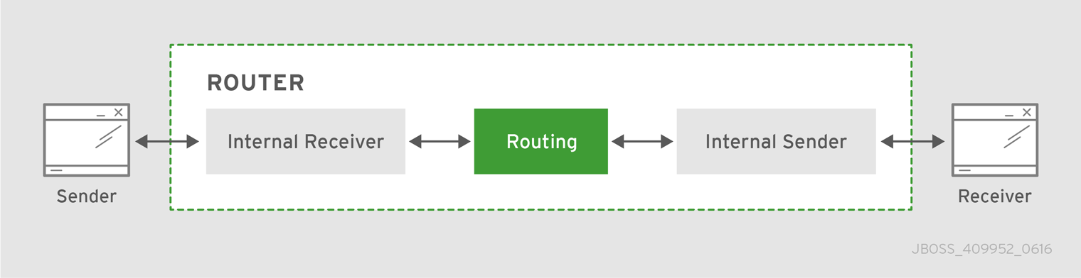
In this diagram, the message producer attaches a link to the router, and then sends a message over the link. When the router receives the message, it identifies the message’s destination based on the message’s address, and then uses its routing table to determine the best route to deliver the message either to its destination or to the next hop in the route. All dispositions (including settlement) are propagated along the same path that the original message transfer took. Flow control is handled between the sender and the router, and then between the router and the receiver.
- Link routing
Routing is performed on link-attach frames, which are chained together to form a virtual messaging path that directly connects a sender and receiver. Once a link route is established, the transfer of message deliveries, flow frames, and dispositions is performed across the link route.
Figure 5.2. Link Routing
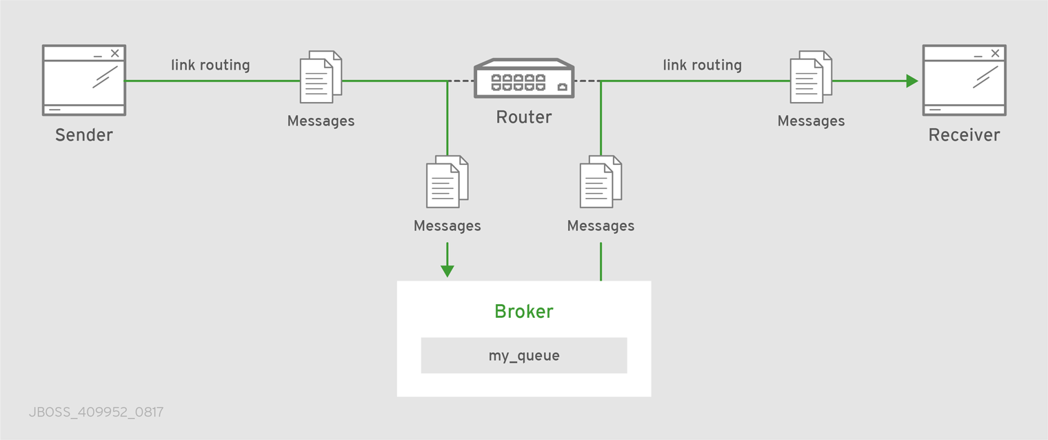
In this diagram, a router is connected to clients and to a broker, and it provides a link route to a queue on the broker (my_queue). The sender connects to the router, and the router propagates the link-attaches to the broker to form a direct link between the sender and the broker. The sender can begin sending messages to the queue, and the router passes the deliveries along the link route directly to the broker queue.
5.1. Comparison of Message Routing and Link Routing
While you can use either message routing or link routing to deliver messages to a destination, they differ in several important ways. Understanding these differences will enable you to choose the proper routing approach for any particular use case.
5.1.1. When to Use Message Routing
Message routing is the default routing mechanism. You can use it to route messages on a per-message basis between clients directly (direct-routed messaging), or to and from broker queues (brokered messaging).
Message routing is best suited to the following requirements:
Default, basic message routing.
AMQ Interconnect automatically routes messages by default, so manual configuration is only required if you want routing behavior that is different than the default.
Message-based routing patterns.
Message routing supports both anycast and multicast routing patterns. You can load-balance individual messages across multiple consumers, and multicast (or fan-out) messages to multiple subscribers.
Sharding messages across multiple broker instances when message delivery order is not important.
Sharding messages from one producer might cause that producer’s messages to be received in a different order than the order in which they were sent.
Message routing is not suitable for any of the following requirements:
Dedicated path through the router network.
For inter-router transfers, all message deliveries are placed on the same inter-router link. This means that the traffic for one address might affect the delivery of the traffic for another address.
Granular, end-to-end flow control.
With message routing, end-to-end flow control is based on the settlement of deliveries and therefore might not be optimal in every case.
- Transaction support.
- Server-side selectors.
5.1.2. When to Use Link Routing
Link routing requires more detailed configuration than message routing as well as an AMQP container that can accept incoming link-attaches (typically a broker). However, link routing enables you to satisfy more advanced use cases than message routing.
You can use link routing if you need to meet any of the following requirements:
Dedicated path through the router network.
With link routing, each link route has dedicated inter-router links through the network. Each link has its own dedicated message buffers, which means that the address will not have "head-of-line" blocking issues with other addresses.
Sharding messages across multiple broker instances with guaranteed delivery order.
Link routing to a sharded queue preserves the delivery order of the producer’s messages by causing all messages on that link to go to the same broker instance.
End-to-end flow control.
Flow control is "real" in that credits flow across the link route from the receiver to the sender.
Transaction support.
Link routing supports local transactions to a single broker. Distributed transactions are not supported.
Server-side selectors.
With a link route, consumers can provide server-side selectors for broker subscriptions.
5.2. Configuring Message Routing
With message routing, routing is performed on messages as producers send them to a router. When a message arrives on a router, the router routes the message and its settlement based on the message’s address and routing pattern.
With message routing, you can do the following:
Route messages between clients (direct-routed, or brokerless messaging)
This involves configuring an address with a routing pattern. All messages sent to the address will be routed based on the routing pattern.
Route messages through a broker queue (brokered messaging)
This involves configuring a waypoint address to identify the broker queue and then connecting the router to the broker. All messages sent to the waypoint address will be routed to the broker queue.
5.2.1. Addresses
Addresses determine how messages flow through your router network. An address designates an endpoint in your messaging network, such as:
- Endpoint processes that consume data or offer a service
- Topics that match multiple consumers to multiple producers
Entities within a messaging broker:
- Queues
- Durable Topics
- Exchanges
When a router receives a message, it uses the message’s address to determine where to send the message (either its destination or one step closer to its destination).
5.2.1.1. Mobile Addresses
Routers consider addresses to be mobile such that any users of an address may be directly connected to any router in a network and may move around the topology. In cases where messages are broadcast to or balanced across multiple consumers, the address users may be connected to multiple routers in the network.
Mobile addresses are rendezvous points for senders and receivers. Messages arrive at the mobile address and are dispatched to their destinations according to the routing defined for the mobile address. The details of these routing patterns are discussed later.
Mobile addresses may be discovered during normal router operation or configured through management settings.
5.2.1.1.1. Discovered Mobile Addresses
Mobile addresses are created when a client creates a link to a source or destination address that is unknown to the router network.
Suppose a service provider wants to offer my-service that clients may use. The service provider must open a receiver link with source address my-service. The router creates a mobile address my-service and propagates the address so that it is known to every router in the network.
Later a client wants to use the service and creates a sending link with target address my-service. The router matches the service provider’s receiver having source address my-service to the client’s sender having target address my-service and routes messages between the two.
Any number of other clients can create links to the service as well. The clients do not have to know where in the router network the service provider is physically located nor are the clients required to connect to a specific router to use the service. Regardless of how many clients are using the service the service provider needs only a single connection and link into the router network.
Another view of this same scenario is when a client tries to use the service before service provider has connected to the network. In this case the router network creates the mobile address my-service as before. However, since the mobile address has only client sender links and no receiver links the router stalls the clients and prevents them from sending any messages. Later, after the service provider connects and creates the receiver link, the router will issue credits to the clients and the messages will begin to flow between the clients and the service.
The service provider can connect, disconnect, and reconnect from a different location without having to change any of the clients or their connections. Imagine having the service running on a laptop. One day the connection is from corporate headquarters and the next day the connection is from some remote location. In this case the service provider’s computer will typically have different host IP addresses for each connection. Using the router network the service provider connects to the router network and offers the named service and the clients connect to the router network and consume from the named service. The router network routes messages between the mobile addresses effectively masking host IP addresses of the service provider and the client systems.
5.2.1.1.2. Configured Mobile Addresses
Mobile addresses may be configured using the router autoLink object. An address created via an autoLink represents a queue, topic, or other service in an external broker. Logically the autoLink addresses are treated by the router network as if the broker had connected to the router and offered the services itself.
For each configured mobile address the router will create a single link to the external resource. Messages flow between sender links and receiver links the same regardless if the mobile address was discovered or configured.
Multiple autoLink objects may define the same address on multiple brokers. In this case the router network creates a sharded resource split between the brokers. Any client can seamlessly send and receive messages from either broker.
Note that the brokers do not need to be clustered or federated to receive this treatment. The brokers may even be from different vendors or be different versions of the same broker yet still work together to provide a larger service platform.
5.2.2. Routing Patterns
Routing patterns define the paths that a message with a mobile address can take across a network. These routing patterns can be used for both direct routing, in which the router distributes messages between clients without a broker, and indirect routing, in which the router enables clients to exchange messages through a broker.
Routing patterns fall into two categories: Anycast (Balanced and Closest) and Multicast. There is no concept of "unicast" in which there is only one consumer for an address.
Anycast distribution delivers each message to one consumer whereas multicast distribution delivers each message to all consumers.
Each address has one of the following routing patterns, which define the path that a message with the address can take across the messaging network:
- Balanced
An anycast method that allows multiple consumers to use the same address. Each message is delivered to a single consumer only, and AMQ Interconnect attempts to balance the traffic load across the router network.
If multiple consumers are attached to the same address, each router determines which outbound path should receive a message by considering each path’s current number of unsettled deliveries. This means that more messages will be delivered along paths where deliveries are settled at higher rates.
NoteAMQ Interconnect neither measures nor uses message settlement time to determine which outbound path to use.
In this scenario, the messages are spread across both receivers regardless of path length:
Figure 5.3. Balanced Message Routing
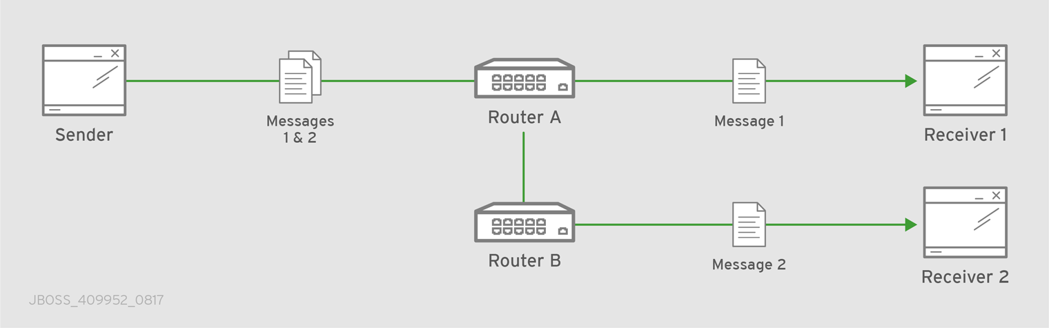
- Closest
An anycast method in which every message is sent along the shortest path to reach the destination, even if there are other consumers for the same address.
AMQ Interconnect determines the shortest path based on the topology cost to reach each of the consumers. If there are multiple consumers with the same lowest cost, messages will be spread evenly among those consumers.
In this scenario, all messages sent by
Senderwill be delivered toReceiver 1:Figure 5.4. Closest Message Routing
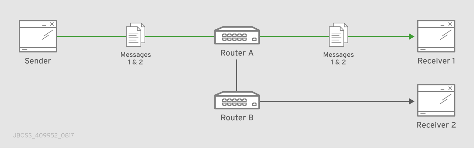
- Multicast
Messages are sent to all consumers attached to the address. Each consumer will receive one copy of the message.
In this scenario, all messages are sent to all receivers:
Figure 5.5. Multicast Message Routing
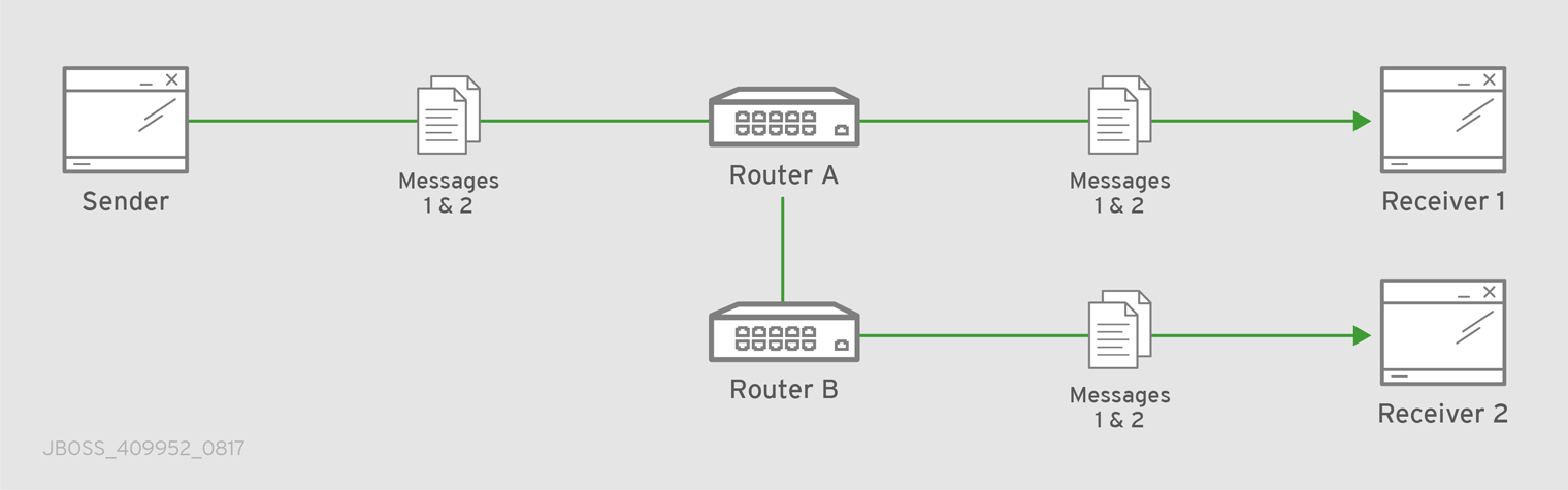
5.2.3. Message Settlement
Message settlement is negotiated between the producer and the router when the producer establishes a link to the router. Depending on the settlement pattern, messages might be delivered with any of the following degrees of reliability:
- At most once
- At least once
- Exactly once
AMQ Interconnect treats all messages as either pre-settled or unsettled, and it is responsible for propagating the settlement of each message it routes.
- Pre-settled
- Sometimes called fire and forget, the router settles the incoming and outgoing deliveries and propagates the settlement to the message’s destination. However, it does not guarantee delivery.
- Unsettled
The router propagates the settlement between the sender and receiver, and guarantees one of the following outcomes:
- The message is delivered and settled, with the consumer’s disposition indicated.
The delivery is settled with a disposition of
RELEASED.This means that the message did not reach its destination.
The delivery is settled with a disposition of
MODIFIED.This means that the message might or might not have reached its destination. The delivery is considered to be "in-doubt" and should be re-sent if "at least once" delivery is required.
- The link, session, or connection to AMQ Interconnect was dropped, and all deliveries are "in-doubt".
5.2.4. Routing Pattern Reliability
The following table describes the levels of reliability provided by each routing pattern:
| Routing pattern | Reliable? |
|---|---|
| Anycast (Balanced or Closest) | Yes, when the message deliveries are unsettled. There is a reliability contract that the router network abides by when delivering unsettled messages to anycast addresses. For every such delivery sent by a producer, the router network guarantees that one of the following outcomes will occur:
|
| Multicast | No. If a producer sends an unsettled delivery, the disposition may be ACCEPTED or RELEASED.
|
5.2.5. Configuring Addresses for Prioritized Message Delivery
You can set the priority level of an address to control how AMQ Interconnect processes messages sent to that address. Within the scope of a connection, AMQ Interconnect attempts to process messages based on their priority. For a connection with a large volume of messages in flight, this lowers the latency for higher-priority messages.
Assigning a high priority level to an address does not guarantee that messages sent to the address will be delivered before messages sent to lower-priority addresses. However, higher-priority messages will travel more quickly through the router network than they otherwise would.
You can also control the priority level of individual messages by setting the priority level in the message header. However, the address priority takes precedence: if you send a prioritized message to an address with a different priority level, the router will use the address priority level.
Procedure
In the router’s configuration file, add or edit an address and assign a priority level.
This example adds an address with the highest priority level. The router will attempt to deliver messages sent to this address before messages with lower priority levels.
address { prefix: my-high-priority-address priority: 9 ... }priority- The priority level to assign to all messages sent to this address. The range of valid priority levels is 0-9, in which the higher the number, the higher the priority. The default is 4.
Additional resources
- For more information about setting the priority level in a message, see the AMQP 1.0 specification.
5.2.6. Routing Messages Between Clients
You can route messages between clients without using a broker. In a brokerless scenario (sometimes called direct-routed messaging), AMQ Interconnect routes messages between clients directly.
To route messages between clients, you configure an address with a routing distribution pattern. When a router receives a message with this address, the message is routed to its destination or destinations based on the address’s routing distribution pattern.
Procedure
In the router’s configuration file, add an
addresssection:address { prefix: ADDRESS_PREFIX distribution: balanced|closest|multicast ... }prefix|patternThe address or group of addresses to which the address settings should be applied. You can specify a prefix to match an exact address or beginning segment of an address. Alternatively, you can specify a pattern to match an address using wildcards.
A prefix matches either an exact address or the beginning segment within an address that is delimited by either a
.or/character. For example, the prefixmy_addresswould match the addressmy_addressas well asmy_address.1andmy_address/1. However, it would not matchmy_address1.A pattern matches an address that corresponds to a pattern. A pattern is a sequence of words delimited by either a
.or/character. You can use wildcard characters to represent a word. The*character matches exactly one word, and the#character matches any sequence of zero or more words.The
*and#characters are reserved as wildcards. Therefore, you should not use them in the message address.For more information about creating address patterns, see Section 5.3.6, “Pattern Matching for Addresses”.
NoteYou can convert a
prefixvalue to apatternby appending/#to it. For example, the prefixa/b/cis equivalent to the patterna/b/c/#.distributionThe message distribution pattern. The default is
balanced, but you can specify any of the following options:-
balanced- Messages sent to the address will be routed to one of the receivers, and the routing network will attempt to balance the traffic load based on the rate of settlement. -
closest- Messages sent to the address are sent on the shortest path to reach the destination. It means that if there are multiple receivers for the same address, only the closest one will receive the message. multicast- Messages are sent to all receivers that are attached to the address in a publish/subscribe model.For more information about message distribution patterns, see Routing Patterns.
-
For information about additional attributes, see address in the
qdrouterd.confman page.Add the same
addresssection to any other routers that need to use the address.The
addressthat you added to this router configuration file only controls how this router distributes messages sent to the address. If you have additional routers in your router network that should distribute messages for this address, then you must add the sameaddresssection to each of their configuration files.
5.2.7. Routing Messages Through a Broker Queue
You can route messages to and from a broker queue to provide clients with access to the queue through a router. In this scenario, clients connect to a router to send and receive messages, and the router routes the messages to or from the broker queue.
You can route messages to a queue hosted on a single broker, or route messages to a sharded queue distributed across multiple brokers.
Figure 5.6. Brokered Messaging
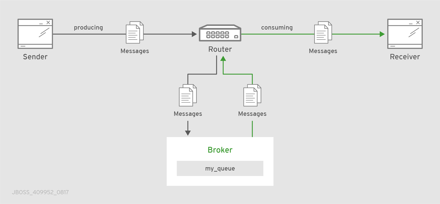
In this diagram, the sender connects to the router and sends messages to my_queue. The router attaches an outgoing link to the broker, and then sends the messages to my_queue. Later, the receiver connects to the router and requests messages from my_queue. The router attaches an incoming link to the broker to receive the messages from my_queue, and then delivers them to the receiver.
You can also route messages to a sharded queue, which is a single, logical queue comprised of multiple, underlying physical queues. Using queue sharding, it is possible to distribute a single queue over multiple brokers. Clients can connect to any of the brokers that hold a shard to send and receive messages.
Figure 5.7. Brokered Messaging with Sharded Queue
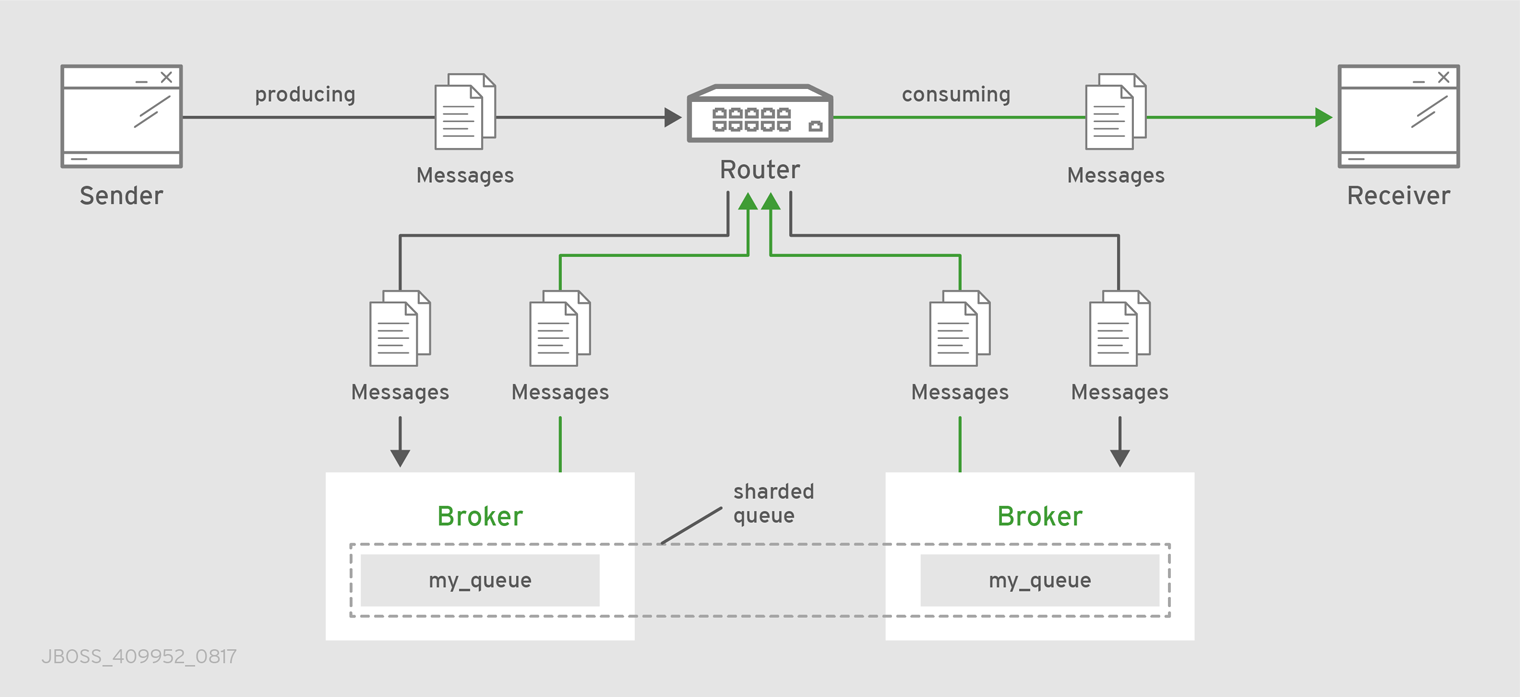
In this diagram, a sharded queue (my_queue) is distributed across two brokers. The router is connected to the clients and to both brokers. The sender connects to the router and sends messages to my_queue. The router attaches an outgoing link to each broker, and then sends messages to each shard (by default, the routing distribution is balanced). Later, the receiver connects to the router and requests all of the messages from my_queue. The router attaches an incoming link to one of the brokers to receive the messages from my_queue, and then delivers them to the receiver.
Procedure
This address identifies the queue to which you want to route messages.
Add autolinks to connect the router to the broker.
Autolinks connect the router to the broker queue identified by the waypoint address.
- If the queue is sharded, add autolinks for each additional broker that hosts a shard.
5.2.7.1. Configuring Waypoint Addresses
A waypoint address identifies a queue on a broker to which you want to route messages. You need to configure the waypoint address on each router that needs to use the address. For example, if a client is connected to Router A to send messages to the broker queue, and another client is connected to Router B to receive those messages, then you would need to configure the waypoint address on both Router A and Router B.
Prerequisites
An incoming connection (listener) to which the clients can connect should be configured. This connection defines how the producers and consumers connect to the router to send and receive messages. For more information, see Section 4.2.2, “Listening for client connections”.
Procedure
Create waypoint addresses on each router that needs to use the address:
address { prefix: ADDRESS_PREFIX waypoint: yes }prefix|patternThe address prefix or pattern that matches the broker queue to which you want to send messages. You can specify a prefix to match an exact address or beginning segment of an address. Alternatively, you can specify a pattern to match an address using wildcards.
A prefix matches either an exact address or the beginning segment within an address that is delimited by either a
.or/character. For example, the prefixmy_addresswould match the addressmy_addressas well asmy_address.1andmy_address/1. However, it would not matchmy_address1.A pattern matches an address that corresponds to a pattern. A pattern is a sequence of words delimited by either a
.or/character. You can use wildcard characters to represent a word. The*character matches exactly one word, and the#character matches any sequence of zero or more words.The
*and#characters are reserved as wildcards. Therefore, you should not use them in the message address.For more information about creating address patterns, see Section 5.3.6, “Pattern Matching for Addresses”.
NoteYou can convert a
prefixvalue to apatternby appending/#to it. For example, the prefixa/b/cis equivalent to the patterna/b/c/#.waypoint-
Set this attribute to
yesso that the router handles messages sent to this address as a waypoint.
5.2.7.2. Connecting a Router to the Broker
After you add waypoint addresses to identify the broker queue, you must connect a router to the broker using autolinks.
With autolinks, client traffic is handled on the router, not the broker. Clients attach their links to the router, and then the router uses internal autolinks to connect to the queue on the broker. Therefore, the queue will always have a single producer and a single consumer regardless of how many clients are attached to the router.
If the connection to the broker fails, AMQ Interconnect automatically attempts to reestablish the connection and reroute message deliveries to any available alternate destinations. However, some deliveries could be returned to the sender with a RELEASED or MODIFIED disposition. Therefore, you should ensure that your clients can handle these deliveries appropriately (generally by resending them).
- If this router is different than the router that is connected to the clients, then add the waypoint address.
Add an outgoing connection to the broker:
connector { name: NAME host: HOST_NAME/ADDRESS port: PORT_NUMBER/NAME role: route-container ... }name-
The name of the
connector. Specify a name that describes the broker. host- Either an IP address (IPv4 or IPv6) or hostname on which the router should connect to the broker.
port- The port number or symbolic service name on which the router should connect to the broker.
role-
Specify
route-containerto indicate that this connection is for an external container (broker).
For information about additional attributes, see connector in the
qdrouterd.confman page.If you want to send messages to the broker queue, create an outgoing autolink to the broker queue:
autoLink { address: ADDRESS connection: CONNECTOR_NAME direction: out ... }address- The address of the broker queue. When the autolink is created, it will be attached to this address.
externalAddress-
An optional alternate address for the broker queue. You use an external address if the broker queue should have a different address than that which the sender uses. In this scenario, senders send messages to the
addraddress, and then the router routes them to the broker queue represented by theexternalAddressaddress. connection|containerID-
How the router should connect to the broker. You can specify either an outgoing connection (
connection) or the container ID of the broker (containerID). direction-
Set this attribute to
outto specify that this autolink can send messages from the router to the broker.
For information about additional attributes, see autoLink in the
qdrouterd.confman page.If you want to receive messages from the broker queue, create an incoming autolink from the broker queue:
autoLink { address: ADDRESS connection: CONNECTOR_NAME direction: in ... }address- The address of the broker queue. When the autolink is created, it will be attached to this address.
externalAddress-
An optional alternate address for the broker queue. You use an external address if the broker queue should have a different address than that which the receiver uses. In this scenario, receivers receive messages from the
addraddress, and the router retrieves them from the broker queue represented by theexternalAddressaddress. connection|containerID-
How the router should connect to the broker. You can specify either an outgoing connection (
connection) or the container ID of the broker (containerID). direction-
Set this attribute to
into specify that this autolink can receive messages from the broker to the router.
For information about additional attributes, see autoLink in the
qdrouterd.confman page.
5.2.8. Handling Undeliverable Messages for an Address
You handle undeliverable messages for an address by configuring autolinks that point to fallback destinations. A fallback destination (such as a queue on a broker) stores messages that are not directly routable to any consumers.
During normal message delivery, AMQ Interconnect delivers messages to the consumers that are attached to the router network. However, if no consumers are reachable, the messages are diverted to any fallback destinations that were configured for the address (if the autolinks that point to the fallback destinations are active). When a consumer reconnects and becomes reachable again, it receives the messages stored at the fallback destination.
AMQ Interconnect preserves the original delivery order for messages stored at a fallback destination. However, when a consumer reconnects, any new messages produced while the queue is draining will be interleaved with the messages stored at the fallback destination.
Prerequisites
The router is connected to a broker.
For more information, see Section 4.2.3, “Connecting to external AMQP containers”.
Procedure
This procedure enables fallback for an address and configures autolinks to connect to the broker queue that provides the fallback destination for the address.
Enable fallback destinations for the address.
address { prefix: my-address enableFallback: yes }Add an outgoing autolink to a queue on the broker.
For the address for which you enabled fallback, if messages are not routable to any consumers, the router will use this autolink to send the messages to a queue on the broker.
autoLink { address: my-address.2 direction: out connection: my-broker fallback: yes }If you want the router to send queued messages to attached consumers as soon as they connect to the router network, add an incoming autolink.
As soon as a consumer attaches to the router, it will receive the messages stored in the broker queue, along with any new messages sent by the producer. The original delivery order of the queued messages is preserved; however, the queued messages will be interleaved with the new messages.
If you do not add the incoming autolink, the messages will be stored on the broker, but will not be sent to consumers when they attach to the router.
autoLink { address: my-address.2 direction: in connection: my-broker fallback: yes }
5.2.9. Example: Routing Messages Through Broker Queues
This example shows how waypoints and autolinks can route messages through a pair of queues on a broker.
5.2.9.1. Router Configuration
connector { 1
name: broker
role: route-container
host: 198.51.100.1
port: 61617
saslMechanisms: ANONYMOUS
}
address { 2
prefix: queue
waypoint: yes
}
autoLink { 3
address: queue.first
direction: in
connection: broker
}
autoLink { 4
address: queue.first
direction: out
connection: broker
}
autoLink { 5
address: queue.second
direction: in
connection: broker
}
autoLink { 6
address: queue.second
direction: out
connection: broker
}- 1
- The outgoing connection from the router to the broker. The
route-containerrole enables the router to connect to an external AMQP container (in this case, a broker). - 2
- The namespace queue on the broker to which the router should route messages. All addresses that start with
queuewill be routed to a queue on the broker. - 3
- The incoming autolink from
queue.firston the broker to the router. - 4
- The outgoing autolink from the router to
queue.firston the broker. - 5
- The incoming autolink from
queue.secondon the broker to the router. - 6
- The outgoing autolink from the router to
queue.secondon the broker.
5.2.9.2. How the Messages are Routed
Initially, when the broker is offline, the autolinks are inactive.
$ qdstat --autolinks AutoLinks addr dir phs extAddr link status lastErr ======================================================== queue.first in 1 inactive queue.first out 0 inactive queue.second in 1 inactive queue.second out 0 inactive
Once the broker is online, the autolinks attempt to activate. In this case, the broker starts with the queue.first queue only, and the queue.first autolinks become active. The queue.second autolinks are in a failed state, because the queue.second queue does not exist on the broker.
$ qdstat --autolinks AutoLinks addr dir phs extAddr link status lastErr =========================================================================== queue.first in 1 6 active queue.first out 0 7 active queue.second in 1 failed Node not found: queue.second queue.second out 0 failed Node not found: queue.second
The producer now connects to the router and sends three messages to queue.first.
$ python simple_send.py -a 127.0.0.1/queue.first -m3 all messages confirmed
The router’s address statistics show that the messages were delivered to the queue.
$ qdstat -a Router Addresses class addr phs distrib in-proc local remote cntnr in out thru to-proc from-proc ======================================================================================================== mobile queue.first 1 balanced 0 0 0 0 0 0 0 0 0 mobile queue.first 0 balanced 0 1 0 0 3 3 0 0 0
The queue.first address appears twice in the output: once for each phase of the address. Phase 0 is for routing messages from producers to the outgoing autolink. Phase 1 is for routing messages from the incoming autolink to the subscribed consumers. In this case, Phase 0 of the address has counted three messages in the in column (the messages that arrived on the router from the producer), and three messages in the out column (the messages that were sent from the router to the broker queue).
The consumer now connects to the router and receives the three messages from queue.first.
$ python simple_recv.py -a 127.0.0.1:5672/queue.first -m3
{u'sequence': int32(1)}
{u'sequence': int32(2)}
{u'sequence': int32(3)}The router’s address statistics now show that all three messages were received by the consumer from the broker queue.
$ qdstat -a Router Addresses class addr phs distrib in-proc local remote cntnr in out thru to-proc from-proc ======================================================================================================== mobile queue.first 1 balanced 0 0 0 0 3 3 0 0 0 mobile queue.first 0 balanced 0 1 0 0 3 3 0 0 0
The command output shows that Phase 1 of the address was used to deliver all three messages from the queue to the consumer.
Even in a multi-router network, and with multiple producers and consumers for queue.first, all deliveries are routed through the queue on the connected broker.
5.3. Configuring Link Routing
Link routing provides an alternative strategy for brokered messaging. A link route represents a private messaging path between a sender and a receiver in which the router passes the messages between end points. You can think of a link route as a "virtual connection" or "tunnel" that travels from a sender, through the router network, to a receiver.
With link routing, routing is performed on link-attach frames, which are chained together to form a virtual messaging path that directly connects a sender and receiver. Once a link route is established, the transfer of message deliveries, flow frames, and dispositions is performed across the link route.
5.3.1. Link Route Addresses
A link route address represents a broker queue, topic, or other service. When a client attaches a link route address to a router, the router propagates a link attachment to the broker resource identified by the address.
Using link route addresses, the router network does not participate in aggregated message distribution. The router simply passes message delivery and settlement between the two end points.
5.3.2. Link Route Routing Patterns
Routing patterns are not used with link routing, because there is a direct link between the sender and receiver. The router only makes a routing decision when it receives the initial link-attach request frame. Once the link is established, the router passes the messages along the link in a balanced distribution.
5.3.3. Link Route Flow Control
Unlike message routing, with link routing, the sender and receiver handle flow control directly: the receiver grants link credits, which is the number of messages it is able to receive. The router sends them directly to the sender, and then the sender sends the messages based on the credits that the receiver granted.
5.3.4. Creating a Link Route
Link routes establish a link between a sender and a receiver that travels through a router. You can configure inward and outward link routes to enable the router to receive link-attaches from clients and to send them to a particular destination.
With link routing, client traffic is handled on the broker, not the router. Clients have a direct link through the router to a broker’s queue. Therefore, each client is a separate producer or consumer.
If the connection to the broker fails, the routed links are detached, and the router will attempt to reconnect to the broker (or its backup). Once the connection is reestablished, the link route to the broker will become reachable again.
From the client’s perspective, the client will see the detached links (that is, the senders or receivers), but not the failed connection. Therefore, if you want the client to reattach dropped links in the event of a broker connection failure, you must configure this functionality on the client. Alternatively, you can use message routing with autolinks instead of link routing. For more information, see Routing Messages through a Broker Queue.
Procedure
In the router configuration file, add an outgoing connection to the broker:
connector { name: NAME host: HOST_NAME/ADDRESS port: PORT_NUMBER/NAME role: route-container ... }name-
The name of the
connector. You should specify a name that describes the broker. host- Either an IP address (IPv4 or IPv6) or hostname on which the router should connect to the broker.
port- The port number or symbolic service name on which the router should connect to the broker.
role-
Specify
route-containerto indicate that this connection is for an external container (broker).
For information about additional attributes, see connector in the
qdrouterd.confman page.If you want clients to send local transactions to the broker, create a link route for the transaction coordinator:
linkRoute { prefix: $coordinator 1 connection: CONNECTOR_NAME direction: in }- 1
- The
$coordinatorprefix designates this link route as a transaction coordinator. When the client opens a transacted session, the requests to start and end the transaction are propagated along this link route to the broker.
AMQ Interconnect does not support routing transactions to multiple brokers. If you have multiple brokers in your environment, choose a single broker and route all transactions to it.
If you want clients to send messages on this link route, create an incoming link route:
linkRoute { prefix: ADDRESS_PREFIX connection: CONNECTOR_NAME direction: in ... }prefix|patternThe address prefix or pattern that matches the broker queue that should be the destination for routed link-attaches. All messages that match this prefix or pattern will be distributed along the link route. You can specify a prefix to match an exact address or beginning segment of an address. Alternatively, you can specify a pattern to match an address using wildcards.
A prefix matches either an exact address or the beginning segment within an address that is delimited by either a
.or/character. For example, the prefixmy_addresswould match the addressmy_addressas well asmy_address.1andmy_address/1. However, it would not matchmy_address1.A pattern matches an address that corresponds to a pattern. A pattern is a sequence of words delimited by either a
.or/character. You can use wildcard characters to represent a word. The*character matches exactly one word, and the#character matches any sequence of zero or more words.The
*and#characters are reserved as wildcards. Therefore, you should not use them in the message address.For more information about creating address patterns, see Section 5.3.6, “Pattern Matching for Addresses”.
NoteYou can convert a
prefixvalue to apatternby appending/#to it. For example, the prefixa/b/cis equivalent to the patterna/b/c/#.connection|containerIDHow the router should connect to the broker. You can specify either an outgoing connection (
connection) or the container ID of the broker (containerID).If multiple brokers are connected to the router through this connection, requests for addresses matching the link route’s prefix or pattern are balanced across the brokers. Alternatively, if you want to specify a particular broker, use
containerIDand add the broker’s container ID.direction-
Set this attribute to
into specify that clients can send messages into the router network on this link route.
For information about additional attributes, see linkRoute in the
qdrouterd.confman page.If you want clients to receive messages on this link route, create an outgoing link route:
linkRoute { prefix: ADDRESS_PREFIX connection: CONNECTOR_NAME direction: out ... }prefix|patternThe address prefix or pattern that matches the broker queue from which you want to receive routed link-attaches. All messages that match this prefix or pattern will be distributed along the link route. You can specify a prefix to match an exact address or beginning segment of an address. Alternatively, you can specify a pattern to match an address using wildcards.
A prefix matches either an exact address or the beginning segment within an address that is delimited by either a
.or/character. For example, the prefixmy_addresswould match the addressmy_addressas well asmy_address.1andmy_address/1. However, it would not matchmy_address1.A pattern matches an address that corresponds to a pattern. A pattern is a sequence of words delimited by either a
.or/character. You can use wildcard characters to represent a word. The*character matches exactly one word, and the#character matches any sequence of zero or more words.The
*and#characters are reserved as wildcards. Therefore, you should not use them in the message address.For more information about creating address patterns, see Section 5.3.6, “Pattern Matching for Addresses”.
NoteYou can convert a
prefixvalue to apatternby appending/#to it. For example, the prefixa/b/cis equivalent to the patterna/b/c/#.connection|containerIDHow the router should connect to the broker. You can specify either an outgoing connection (
connection) or the container ID of the broker (containerID).If multiple brokers are connected to the router through this connection, requests for addresses matching the link route’s prefix or pattern are balanced across the brokers. Alternatively, if you want to specify a particular broker, use
containerIDand add the broker’s container ID.direction-
Set this attribute to
outto specify that this link route is for receivers.
For information about additional attributes, see linkRoute in the
qdrouterd.confman page.
5.3.5. Example: Using a Link Route to Provide Client Isolation
This example shows how a link route can connect a client to a message broker that is on a different private network.
Router Network with Isolated Clients
Public Network
+-----------------+
| +-----+ |
| B1 | Rp | |
| +/--\-+ |
| / \ |
| / \ |
+----/--------\---+
/ \
/ \
/ \
Private Net A / \ Private Net B
+--------------/--+ +---\-------------+
| +---/-+ | | +--\--+ |
| B2 | Ra | | | | Rb | C1 |
| +-----+ | | +-----+ |
| | | |
| | | |
+-----------------+ +-----------------+
Client C1 is constrained by firewall policy to connect to the router in its own network (Rb). However, it can use a link route to access queues, topics, and any other AMQP services that are provided on message brokers B1 and B2 — even though they are on different networks.
In this example, client C1 needs to receive messages from b2.event-queue, which is hosted on broker B2 in Private Net A. A link route connects the client and broker even though neither of them is aware that there is a router network between them.
5.3.5.1. Router Configuration
To enable client C1 to receive messages from b2.event-queue on broker B2, router Ra must be able to do the following:
-
Connect to broker
B2 -
Route links to and from broker
B2 -
Advertise itself to the router network as a valid destination for links that have a
b2.event-queueaddress.
The relevant part of the configuration file for router Ra shows the following:
connector { 1
name: broker
role: route-container
host: 198.51.100.1
port: 61617
saslMechanisms: ANONYMOUS
}
linkRoute { 2
prefix: b2
direction: in
connection: broker
}
linkRoute { 3
prefix: b2
direction: out
connection: broker
}- 1
- The outgoing connection from the router to broker
B2. Theroute-containerrole enables the router to connect to an external AMQP container (in this case, a broker). - 2
- The incoming link route for receiving links from client senders. Any sender with a target whose address begins with
b2will be routed to brokerB2using thebrokerconnector. - 3
- The outgoing link route for sending links to client receivers. Any receivers whose source address begins with
b2will be routed to brokerB2using thebrokerconnector.
This configuration enables router Ra to advertise itself as a valid destination for targets and sources starting with b2. It also enables the router to connect to broker B2, and to route links to and from queues starting with the b2 prefix.
While not required, routers Rp and Rb should also have the same configuration.
5.3.5.2. How the Client Receives Messages
By using the configured link route, client C1 can receive messages from broker B2 even though they are on different networks.
Router Ra establishes a connection to broker B2. Once the connection is open, Ra tells the other routers (Rp and Rb) that it is a valid destination for link routes to the b2 prefix. This means that sender and receiver links attached to Rb or Rp will be routed along the shortest path to Ra, which then routes them to broker B2.
To receive messages from the b2.event-queue on broker B2, client C1 attaches a receiver link with a source address of b2.event-queue to its local router, Rb. Because the address matches the b2 prefix, Rb routes the link to Rp, which is the next hop in the route to its destination. Rp routes the link to Ra, which routes it to broker B2. Client C1 now has a receiver established, and it can begin receiving messages.
If broker B2 is unavailable for any reason, router Ra will not advertise itself as a destination for b2 addresses. In this case, routers Rb and Rp will reject link attaches that should be routed to broker B2 with an error message indicating that there is no route available to the destination.
5.3.6. Pattern Matching for Addresses
In some router configuration scenarios, you might need to use pattern matching to match a range of addresses rather than a single, literal address. Address patterns match any address that corresponds to the pattern.
An address pattern is a sequence of tokens (typically words) that are delimited by either . or / characters. They also can contain special wildcard characters that represent words:
-
*represents exactly one word -
#represents zero or more words
Example 5.1. Address Pattern
This address contains two tokens, separated by the / delimiter:
my/address
Example 5.2. Address Pattern with Wildcard
This address contains three tokens. The * is a wildcard, representing any single word that might be between my and address:
my/*/address
The following table shows some address patterns and examples of the addresses that would match them:
| This pattern… | Matches… | But not… |
|---|---|---|
|
|
|
|
|
|
|
|
|
|
|
|
|
|
|
|
Chapter 6. Monitoring and managing the router network
6.1. Logging
Logging enables you to diagnose error and performance issues with AMQ Interconnect.
AMQ Interconnect consists of internal modules that provide important information about the router. For each module, you can specify logging levels, the format of the log file, and the location to which the logs should be written.
6.1.1. Logging Modules
AMQ Interconnect logs are broken into different categories called logging modules. Each module provides important information about a particular aspect of AMQ Interconnect.
6.1.1.1. The DEFAULT Logging Module
The default module. This module applies defaults to all of the other logging modules.
6.1.1.2. The ROUTER Logging Module
This module provides information and statistics about the local router. This includes how the router connects to other routers in the network, and information about the remote destinations that are directly reachable from the router (link routes, waypoints, autolinks, and so on).
Example 6.1. Using the ROUTER log to trace connections and links
In this example, ROUTER logs show the lifecycle of a connection and a link that is associated with it.
2019-04-05 14:54:38.037248 -0400 ROUTER (info) [C1] Connection Opened: dir=in host=127.0.0.1:55440 vhost= encrypted=no auth=no user=anonymous container_id=95e55424-6c0a-4a5c-8848-65a3ea5cc25a props= 1 2019-04-05 14:54:38.038137 -0400 ROUTER (info) [C1][L6] Link attached: dir=in source={<none> expire:sess} target={$management expire:sess} 2 2019-04-05 14:54:38.041103 -0400 ROUTER (info) [C1][L6] Link lost: del=1 presett=0 psdrop=0 acc=1 rej=0 rel=0 mod=0 delay1=0 delay10=0 3 2019-04-05 14:54:38.041154 -0400 ROUTER (info) [C1] Connection Closed 4
- 1
- The connection is opened. Each connection has a unique ID (
C1). The log also shows some information about the connection. - 2
- A link is attached over the connection. The link is identified with a unique ID (
L6). The log also shows the direction of the link, and the source and target addresses. - 3
- The link is detached. The log shows the link’s terminal statistics.
- 4
- The connection is closed.
6.1.1.3. The ROUTER_HELLO Logging Module
This module provides information about the Hello protocol used by interior routers to exchange Hello messages, which include information about the router’s ID and a list of its reachable neighbors (the other routers with which this router has bidirectional connectivity).
The logs for this module are helpful for monitoring or resolving issues in the network topology, and for determining to which other routers a router is connected, and the hop-cost for each of those connections.
In this example, on Router.A, the ROUTER_HELLO log shows that it is connected to Router.B, and that Router.B is connected to Router.A and Router.C:
Tue Jun 7 13:50:21 2016 ROUTER_HELLO (trace) RCVD: HELLO(id=Router.B area=0 inst=1465307413 seen=['Router.A', 'Router.C']) 1 Tue Jun 7 13:50:21 2016 ROUTER_HELLO (trace) SENT: HELLO(id=Router.A area=0 inst=1465307416 seen=['Router.B']) 2 Tue Jun 7 13:50:22 2016 ROUTER_HELLO (trace) RCVD: HELLO(id=Router.B area=0 inst=1465307413 seen=['Router.A', 'Router.C']) Tue Jun 7 13:50:22 2016 ROUTER_HELLO (trace) SENT: HELLO(id=Router.A area=0 inst=1465307416 seen=['Router.B'])
On Router.B, the ROUTER_HELLO log shows the same router topology from a different perspective:
Tue Jun 7 13:50:18 2016 ROUTER_HELLO (trace) SENT: HELLO(id=Router.B area=0 inst=1465307413 seen=['Router.A', 'Router.C']) 1 Tue Jun 7 13:50:18 2016 ROUTER_HELLO (trace) RCVD: HELLO(id=Router.A area=0 inst=1465307416 seen=['Router.B']) 2 Tue Jun 7 13:50:19 2016 ROUTER_HELLO (trace) RCVD: HELLO(id=Router.C area=0 inst=1465307411 seen=['Router.B']) 3
6.1.1.4. The ROUTER_LS Logging Module
This module provides information about link-state data between routers, including Router Advertisement (RA), Link State Request (LSR), and Link State Update (LSU) messages.
Periodically, each router sends an LSR to the other routers and receives an LSU with the requested information. Exchanging the above information, each router can compute the next hops in the topology, and the related costs.
This example shows the RA, LSR, and LSU messages sent between three routers:
Tue Jun 7 14:10:02 2016 ROUTER_LS (trace) SENT: LSR(id=Router.A area=0) to: Router.C Tue Jun 7 14:10:02 2016 ROUTER_LS (trace) SENT: LSR(id=Router.A area=0) to: Router.B Tue Jun 7 14:10:02 2016 ROUTER_LS (trace) SENT: RA(id=Router.A area=0 inst=1465308600 ls_seq=1 mobile_seq=1) 1 Tue Jun 7 14:10:02 2016 ROUTER_LS (trace) RCVD: LSU(id=Router.B area=0 inst=1465308595 ls_seq=2 ls=LS(id=Router.B area=0 ls_seq=2 peers={'Router.A': 1L, 'Router.C': 1L})) 2 Tue Jun 7 14:10:02 2016 ROUTER_LS (trace) RCVD: LSR(id=Router.B area=0) Tue Jun 7 14:10:02 2016 ROUTER_LS (trace) SENT: LSU(id=Router.A area=0 inst=1465308600 ls_seq=1 ls=LS(id=Router.A area=0 ls_seq=1 peers={'Router.B': 1})) Tue Jun 7 14:10:02 2016 ROUTER_LS (trace) RCVD: RA(id=Router.C area=0 inst=1465308592 ls_seq=1 mobile_seq=0) Tue Jun 7 14:10:02 2016 ROUTER_LS (trace) SENT: LSR(id=Router.A area=0) to: Router.C Tue Jun 7 14:10:02 2016 ROUTER_LS (trace) RCVD: LSR(id=Router.C area=0) 3 Tue Jun 7 14:10:02 2016 ROUTER_LS (trace) SENT: LSU(id=Router.A area=0 inst=1465308600 ls_seq=1 ls=LS(id=Router.A area=0 ls_seq=1 peers={'Router.B': 1})) Tue Jun 7 14:10:02 2016 ROUTER_LS (trace) RCVD: LSU(id=Router.C area=0 inst=1465308592 ls_seq=1 ls=LS(id=Router.C area=0 ls_seq=1 peers={'Router.B': 1L})) 4 Tue Jun 7 14:10:03 2016 ROUTER_LS (trace) Computed next hops: {'Router.C': 'Router.B', 'Router.B': 'Router.B'} 5 Tue Jun 7 14:10:03 2016 ROUTER_LS (trace) Computed costs: {'Router.C': 2L, 'Router.B': 1} Tue Jun 7 14:10:03 2016 ROUTER_LS (trace) Computed valid origins: {'Router.C': [], 'Router.B': []}
- 1
Router.Asent LSR requests and an RA advertisement to the other routers on the network.- 2
Router.Areceived an LSU fromRouter.B, which has two peers:Router.A, andRouter.C(with a cost of1).- 3
Router.Areceived an LSR from bothRouter.BandRouter.C, and replied with an LSU.- 4
Router.Areceived an LSU fromRouter.C, which only has one peer:Router.B(with a cost of1).- 5
- After the LSR and LSU messages are exchanged,
Router.Acomputed the router topology with the related costs.
6.1.1.5. The ROUTER_MA Logging Module
This module provides information about the exchange of mobile address information between routers, including Mobile Address Request (MAR) and Mobile Address Update (MAU) messages exchanged between routers. You can use this log to monitor the state of mobile addresses attached to each router.
This example shows the MAR and MAU messages sent between three routers:
Tue Jun 7 14:27:20 2016 ROUTER_MA (trace) SENT: MAU(id=Router.A area=0 mobile_seq=1 add=['Cmy_queue', 'Dmy_queue', 'M0my_queue_wp'] del=[]) 1 Tue Jun 7 14:27:21 2016 ROUTER_MA (trace) RCVD: MAR(id=Router.C area=0 have_seq=0) 2 Tue Jun 7 14:27:21 2016 ROUTER_MA (trace) SENT: MAU(id=Router.A area=0 mobile_seq=1 add=['Cmy_queue', 'Dmy_queue', 'M0my_queue_wp'] del=[]) Tue Jun 7 14:27:22 2016 ROUTER_MA (trace) RCVD: MAR(id=Router.B area=0 have_seq=0) 3 Tue Jun 7 14:27:22 2016 ROUTER_MA (trace) SENT: MAU(id=Router.A area=0 mobile_seq=1 add=['Cmy_queue', 'Dmy_queue', 'M0my_queue_wp'] del=[]) Tue Jun 7 14:27:39 2016 ROUTER_MA (trace) RCVD: MAU(id=Router.C area=0 mobile_seq=1 add=['M0my_test'] del=[]) 4 Tue Jun 7 14:27:51 2016 ROUTER_MA (trace) RCVD: MAU(id=Router.C area=0 mobile_seq=2 add=[] del=['M0my_test']) 5
- 1
Router.Asent MAU messages to the other routers in the network to notify them about the addresses added formy_queueandmy_queue_wp.- 2
Router.Areceived a MAR message in response fromRouter.C.- 3
Router.Areceived another MAR message in response fromRouter.B.- 4
Router.Csent a MAU message to notify the other routers that it added and address formy_test.- 5
Router.Csent another MAU message to notify the other routers that it deleted the address formy_test(because the receiver is detached).
6.1.1.6. The MESSAGE Logging Module
This module provides information about AMQP messages sent and received by the router, including information about the address, body, and link. You can use this log to find high-level information about messages on a particular router.
In this example, Router.A has sent and received some messages related to the Hello protocol, and sent and received some other messages on a link for a mobile address:
Tue Jun 7 14:36:54 2016 MESSAGE (trace) Sending Message{to='amqp:/_topo/0/Router.B/qdrouter' body='\d1\00\00\00\1b\00\00\00\04\a1\02id\a1\08R'} on link qdlink.p9XmBm19uDqx50R
Tue Jun 7 14:36:54 2016 MESSAGE (trace) Received Message{to='amqp:/_topo/0/Router.A/qdrouter' body='\d1\00\00\00\8e\00\00\00
\a1\06ls_se'} on link qdlink.phMsJOq7YaFsGAG
Tue Jun 7 14:36:54 2016 MESSAGE (trace) Received Message{ body='\d1\00\00\00\10\00\00\00\02\a1\08seque'} on link qdlink.FYHqBX+TtwXZHfV
Tue Jun 7 14:36:54 2016 MESSAGE (trace) Sending Message{ body='\d1\00\00\00\10\00\00\00\02\a1\08seque'} on link qdlink.yU1tnPs5KbMlieM
Tue Jun 7 14:36:54 2016 MESSAGE (trace) Sending Message{to='amqp:/_local/qdhello' body='\d1\00\00\00G\00\00\00\08\a1\04seen\d0'} on link qdlink.p9XmBm19uDqx50R
Tue Jun 7 14:36:54 2016 MESSAGE (trace) Sending Message{to='amqp:/_topo/0/Router.C/qdrouter' body='\d1\00\00\00\1b\00\00\00\04\a1\02id\a1\08R'} on link qdlink.p9XmBm19uDqx50R6.1.1.7. The SERVER Logging Module
This module provides information about how the router is listening for and connecting to other containers in the network (such as clients, routers, and brokers). This information includes the state of AMQP messages sent and received by the broker (open, begin, attach, transfer, flow, and so on), and the related content of those messages.
For example, this log shows details about how the router handled a link attachment:
Tue Jun 7 14:39:52 2016 SERVER (trace) [2]: <- AMQP
Tue Jun 7 14:39:52 2016 SERVER (trace) [1]: <- AMQP
Tue Jun 7 14:39:52 2016 SERVER (trace) [1]:0 <- @open(16) [container-id="Router.B", max-frame-size=16384, channel-max=32767, idle-time-out=8000, offered-capabilities=:"ANONYMOUS-RELAY", properties={:product="qpid-dispatch-router", :version="0.6.0"}]
Tue Jun 7 14:39:52 2016 SERVER (trace) [1]:0 -> @begin(17) [next-outgoing-id=0, incoming-window=15, outgoing-window=2147483647]
Tue Jun 7 14:39:52 2016 SERVER (trace) [1]:RAW: "\x00\x00\x00\x1e\x02\x00\x00\x00\x00S\x11\xd0\x00\x00\x00\x0e\x00\x00\x00\x04@R\x00R\x0fp\x7f\xff\xff\xff"
Tue Jun 7 14:39:52 2016 SERVER (trace) [1]:1 -> @begin(17) [next-outgoing-id=0, incoming-window=15, outgoing-window=2147483647]
Tue Jun 7 14:39:52 2016 SERVER (trace) [1]:RAW: "\x00\x00\x00\x1e\x02\x00\x00\x01\x00S\x11\xd0\x00\x00\x00\x0e\x00\x00\x00\x04@R\x00R\x0fp\x7f\xff\xff\xff"
Tue Jun 7 14:39:52 2016 SERVER (trace) [1]:0 -> @attach(18) [name="qdlink.uSSeXPSfTHhxo8d", handle=0, role=true, snd-settle-mode=2, rcv-settle-mode=0, source=@source(40) [durable=0, expiry-policy=:"link-detach", timeout=0, dynamic=false, capabilities=:"qd.router"], target=@target(41) [durable=0, expiry-policy=:"link-detach", timeout=0, dynamic=false, capabilities=:"qd.router"], initial-delivery-count=0]
Tue Jun 7 14:39:52 2016 SERVER (trace) [1]:RAW: "\x00\x00\x00\x91\x02\x00\x00\x00\x00S\x12\xd0\x00\x00\x00\x81\x00\x00\x00\x0a\xa1\x16qdlink.uSSeXPSfTHhxo8dR\x00AP\x02P\x00\x00S(\xd0\x00\x00\x00'\x00\x00\x00\x0b@R\x00\xa3\x0blink-detachR\x00B@@@@@\xa3\x09qd.router\x00S)\xd0\x00\x00\x00#\x00\x00\x00\x07@R\x00\xa3\x0blink-detachR\x00B@\xa3\x09qd.router@@R\x00"6.1.1.8. The AGENT Logging Module
This module provides information about configuration changes made to the router from either editing the router’s configuration file or using qdmanage.
In this example, on Router.A, address, linkRoute, and autoLink entities were added to the router’s configuration file. When the router was started, the AGENT module applied these changes, and they are now viewable in the log:
Tue Jun 7 15:07:32 2016 AGENT (debug) Add entity: ConnectorEntity(addr=127.0.0.1, allowRedirect=True, cost=1, host=127.0.0.1, identity=connector/127.0.0.1:5672:BROKER, idleTimeoutSeconds=16, maxFrameSize=65536, name=BROKER, port=5672, role=route-container, stripAnnotations=both, type=org.apache.qpid.dispatch.connector, verifyHostname=True) Tue Jun 7 15:07:32 2016 AGENT (debug) Add entity: RouterConfigAddressEntity(distribution=closest, identity=router.config.address/0, name=router.config.address/0, prefix=my_address, type=org.apache.qpid.dispatch.router.config.address, waypoint=False) Tue Jun 7 15:07:32 2016 AGENT (debug) Add entity: RouterConfigAddressEntity(distribution=balanced, identity=router.config.address/1, name=router.config.address/1, prefix=my_queue_wp, type=org.apache.qpid.dispatch.router.config.address, waypoint=True) Tue Jun 7 15:07:32 2016 AGENT (debug) Add entity: RouterConfigLinkrouteEntity(connection=BROKER, direction=in, distribution=linkBalanced, identity=router.config.linkRoute/0, name=router.config.linkRoute/0, prefix=my_queue, type=org.apache.qpid.dispatch.router.config.linkRoute) Tue Jun 7 15:07:32 2016 AGENT (debug) Add entity: RouterConfigLinkrouteEntity(connection=BROKER, direction=out, distribution=linkBalanced, identity=router.config.linkRoute/1, name=router.config.linkRoute/1, prefix=my_queue, type=org.apache.qpid.dispatch.router.config.linkRoute) Tue Jun 7 15:07:32 2016 AGENT (debug) Add entity: RouterConfigAutolinkEntity(address=my_queue_wp, connection=BROKER, direction=in, identity=router.config.autoLink/0, name=router.config.autoLink/0, type=org.apache.qpid.dispatch.router.config.autoLink) Tue Jun 7 15:07:32 2016 AGENT (debug) Add entity: RouterConfigAutolinkEntity(address=my_queue_wp, connection=BROKER, direction=out, identity=router.config.autoLink/1, name=router.config.autoLink/1, type=org.apache.qpid.dispatch.router.config.autoLink)
6.1.1.9. The CONTAINER Logging Module
This module provides information about the nodes related to the router. This includes only the AMQP relay node.
Tue Jun 7 14:46:18 2016 CONTAINER (trace) Container Initialized Tue Jun 7 14:46:18 2016 CONTAINER (trace) Node Type Registered - router Tue Jun 7 14:46:18 2016 CONTAINER (trace) Node of type 'router' installed as default node
6.1.1.10. The ERROR Logging Module
This module provides detailed information about error conditions encountered during execution.
In this example, Router.A failed to start when an incorrect path was specified for the router’s configuration file:
$ sudo qdrouterd --conf xxx
Wed Jun 15 09:53:28 2016 ERROR (error) Python: Exception: Cannot load configuration file xxx: [Errno 2] No such file or directory: 'xxx'
Wed Jun 15 09:53:28 2016 ERROR (error) Traceback (most recent call last):
File "/usr/lib/qpid-dispatch/python/qpid_dispatch_internal/management/config.py", line 155, in configure_dispatch
config = Config(filename)
File "/usr/lib/qpid-dispatch/python/qpid_dispatch_internal/management/config.py", line 41, in __init__
self.load(filename, raw_json)
File "/usr/lib/qpid-dispatch/python/qpid_dispatch_internal/management/config.py", line 123, in load
with open(source) as f:
Exception: Cannot load configuration file xxx: [Errno 2] No such file or directory: 'xxx'
Wed Jun 15 09:53:28 2016 MAIN (critical) Router start-up failed: Python: Exception: Cannot load configuration file xxx: [Errno 2] No such file or directory: 'xxx'
qdrouterd: Python: Exception: Cannot load configuration file xxx: [Errno 2] No such file or directory: 'xxx'6.1.1.11. The POLICY Logging Module
This module provides information about policies that have been configured for the router.
In this example, Router.A has no limits on maximum connections, and the default application policy is disabled:
Tue Jun 7 15:07:32 2016 POLICY (info) Policy configured maximumConnections: 0, policyFolder: '', access rules enabled: 'false' Tue Jun 7 15:07:32 2016 POLICY (info) Policy fallback defaultApplication is disabled
6.1.2. Configuring Logging
You can specify the types of events that should be logged, the format of the log entries, and where those entries should be sent.
Procedure
In the router’s configuration file, add a
logsection to set the default logging properties:log { module: DEFAULT enable: LOGGING_LEVEL includeTimestamp: yes ... }module-
Specify
DEFAULT. enableThe logging level. You can specify any of the following levels (from lowest to highest):
-
trace- provides the most information, but significantly affects system performance -
debug- useful for debugging, but affects system performance -
info- provides general information without affecting system performance -
notice- provides general information, but is less verbose thaninfo -
warning- provides information about issues you should be aware of, but which are not errors -
error- error conditions that you should address -
critical- critical system issues that you must address immediately
To specify multiple levels, use a comma-separated list. You can also use
+to specify a level and all levels above it. For example,trace,debug,warning+enables trace, debug, warning, error, and critical levels. For default logging, you should typically use theinfo+ornotice+level. These levels will provide general information, warnings, and errors for all modules without affecting the performance of AMQ Interconnect.-
includeTimestamp-
Set this to
yesto include the timestamp in all logs.
For information about additional log attributes, see log in the
qdrouterd.confman page.Add an additional
logsection for each logging module that should not follow the default logging configuration:log { module: MODULE_NAME enable: LOGGING_LEVEL ... }module- The name of the module for which you are configuring logging. For a list of valid modules, see Section 6.1.1, “Logging Modules”.
enableThe logging level. You can specify any of the following levels (from lowest to highest):
-
trace- provides the most information, but significantly affects system performance -
debug- useful for debugging, but affects system performance -
info- provides general information without affecting system performance -
notice- provides general information, but is less verbose thaninfo -
warning- provides information about issues you should be aware of, but which are not errors -
error- error conditions that you should address -
critical- critical system issues that you must address immediately
To specify multiple levels, use a comma-separated list. You can also use
+to specify a level and all levels above it. For example,trace,debug,warning+enables trace, debug, warning, error, and critical levels. For default logging, you should typically use theinfo+ornotice+level. These levels will provide general information, warnings, and errors for all modules without affecting the performance of AMQ Interconnect.-
For information about additional log attributes, see log in the
qdrouterd.confman page.
6.1.3. Viewing Log Entries
You may need to view log entries to diagnose errors, performance problems, and other important issues. A log entry consists of an optional timestamp, the logging module, the logging level, and the log message.
6.1.3.1. Viewing Log Entries on the Console
By default, log entries are logged to the console, and you can view them there. However, if the output attribute is set for a particular logging module, then you can find those log entries in the specified location (stderr, syslog, or a file).
6.1.3.2. Viewing Log Entries on the CLI
You can use the qdstat tool to view a list of recent log entries.
Procedure
Use the
qdstat --logcommand to view recent log entries.You can use the
--limitparameter to limit the number of log entries that are displayed. For more information aboutqdstat, see qdstat man page.This example displays the last three log entries for
Router.A:$ qdstat --log --limit=3 -r ROUTER.A Wed Jun 7 17:49:32 2017 ROUTER (none) Core action 'link_deliver' Wed Jun 7 17:49:32 2017 ROUTER (none) Core action 'send_to' Wed Jun 7 17:49:32 2017 SERVER (none) [2]:0 -> @flow(19) [next-incoming-id=1, incoming-window=61, next-outgoing-id=0, outgoing-window=2147483647, handle=0, delivery-count=1, link-credit=250, drain=false]
6.2. Using AMQ Console
AMQ Console is a web console for monitoring the status and performance of AMQ Interconnect router networks.
Prerequisites
AMQ Console requires the
qpid-dispatch-consolepackage.For more information, see Section 2.1, “Installing AMQ Interconnect”.
6.2.1. Setting up access to the web console
Before you can access the web console, you must configure a listener to accept HTTP connections for the web console and serve the console files.
Procedure
- On the router from which you want to access the web console, open the /etc/qpid-dispatch/qdrouterd.conf configuration file.
Add a
listenerto serve the console.This example creates a
listenerthat clients can use to access the web console:listener { host: 0.0.0.0 port: 8672 role: normal http: true httpRootDir: /usr/share/qpid-dispatch/console }host- The IP address (IPv4 or IPv6) or hostname on which the router will listen.
port- The port number or symbolic service name on which the router will listen.
role-
The role of the connection. Specify
normalto indicate that this connection is used for client traffic. http-
Set this attribute to
trueto specify that thislistenershould accept HTTP connections instead of plain AMQP connections. httpRootDir-
Specify the absolute path to the directory that contains the web console HTML files. The default directory is
/usr/share/qpid-dispatch/console.
If you want to secure access to the console, secure the
listener.For more information, see Section 4.3.2, “Securing incoming client connections”. This example adds basic user name and password authentication using SASL PLAIN:
listener { host: 0.0.0.0 port: 8672 role: normal http: true httpRootDir: /usr/share/qpid-dispatch/console authenticatePeer: yes saslMechanisms: PLAIN }- If you want to set up access to the web console from any other router in the router network, repeat this procedure for each router.
6.2.2. Accessing the web console
You can access the web console from a web browser.
Procedure
In a web browser, navigate to the web console URL.
The web console URL is the <host>:<port> from the
listenerthat you created to serve the web console. For example:localhost:8672.The AMQ Console opens. If you set up user name and password authentication, the Connect tab is displayed.
If necessary, log in to the web console.
If you set up user name and password authentication, enter your user name and password to access the web console.
The syntax for the user name is <user>@<domain>. For example:
admin@my-domain.
6.2.3. Monitoring the router network using the web console
In the web console, you use the tabs to monitor the router network.
| This tab… | Provides… |
|---|---|
|
| Aggregated information about routers, addresses, links, connections, and logs. |
|
|
Detailed information about each AMQP management entity for each router in the router network. Some of the attributes have charts that you can add to the |
|
| A graphical view of the router network, including routers, clients, and brokers. The topology shows how the routers are connected, and how messages are flowing through the network. |
|
|
Graphs of the information selected on the |
|
| A chord diagram showing the real-time message flow by address. |
|
| The management schema that controls each of the routers in the router network. |
6.2.4. Closing a connection
If a consumer is processing messages too slowly, or has stopped processing messages without settling its deliveries, you can close the connection. When you close the connection, the "stuck" deliveries are released (meaning they are not delivered to any consumers).
Procedure
Identify any connections with slow or stuck consumers.
- Navigate to → .
Click a connection, and then click Links.
The Rate, Delayed 10 sec, and Delayed 1 sec columns indicate if there are any slow or stuck consumers on the connection.
- Click to close the connection.
6.3. Monitoring AMQ Interconnect Using qdstat
You can use qdstat to view the status of routers on your router network. For example, you can view information about the attached links and configured addresses, available connections, and nodes in the router network.
6.3.1. Syntax for Using qdstat
You can use qdstat with the following syntax:
$ qdstat OPTION [CONNECTION_OPTIONS] [SECURE_CONNECTION_OPTIONS]
This specifies:
-
An
optionfor the type of information to view. One or more optional
connection_optionsto specify a router for which to view the information.If you do not specify a connection option,
qdstatconnects to the router listening on localhost and the default AMQP port (5672).-
The
secure_connection_optionsif the router for which you want to view information only accepts secure connections.
For more information about qdstat, see the qdstat man page.
6.3.2. Viewing General Statistics for a Router
You can view information about a router in the router network, such as its working mode and ID.
Procedure
Use the following command:
$ qdstat -g [CONNECTION_OPTIONS]This example shows general statistics for the local router:
$ qdstat -g Router Statistics attr value ============================================= Version 1.2.0 Mode standalone Router Id Router.A Link Routes 0 Auto Links 0 Links 2 Nodes 0 Addresses 4 Connections 1 Presettled Count 0 Dropped Presettled Count 0 Accepted Count 2 Rejected Count 0 Released Count 0 Modified Count 0 Ingress Count 2 Egress Count 1 Transit Count 0 Deliveries from Route Container 0 Deliveries to Route Container 0
6.3.3. Viewing a List of Connections to a Router
You can view:
- Connections from clients (sender/receiver)
- Connections from and to other routers in the network
- Connections to other containers (such as brokers)
- Connections from the tool itself
Procedure
Use this command:
$ qdstat -c [CONNECTION_OPTIONS]For more information about the fields displayed by this command, see the qdstat -c output columns.
In this example, two clients are connected to
Router.A.Router.Ais connected toRouter.Band a broker.Viewing the connections on Router.A displays the following:
$ qdstat -c -r Router.A Connections id host container role dir security authentication tenant ================================================================================================================================== 2 127.0.0.1:5672 route-container out no-security anonymous-user 1 10 127.0.0.1:5001 Router.B inter-router out no-security anonymous-user 2 12 localhost.localdomain:42972 161211fe-ba9e-4726-9996-52d6962d1276 normal in no-security anonymous-user 3 14 localhost.localdomain:42980 a35fcc78-63d9-4bed-b57c-053969c38fda normal in no-security anonymous-user 4 15 localhost.localdomain:42982 0a03aa5b-7c45-4500-8b38-db81d01ce651 normal in no-security anonymous-user 5
- 1
- This connection shows that
Router.Ais connected to a broker, because theroleisroute-container, and thedirisout. - 2
Router.Ais also connected to another router on the network (theroleisinter-router), establishing an output connection (thedirisout).- 3 4
- These connections show that two clients are connected to
Router.A, because theroleisnormal, and thedirisin. - 5
- The connection from
qdstattoRouter.A. This is the connection thatqdstatuses to queryRouter.Aand display the command output.
Router.Ais connected toRouter.B. Viewing the connections onRouter.Bdisplays the following:$ qdstat -c -r Router.B Connections id host container role dir security authentication tenant ==================================================================================================== 1 localhost.localdomain:51848 Router.A inter-router in no-security anonymous-user 1- 1
- This connection shows that
Router.Bis connected toRouter.Athrough an incoming connection (theroleisinter-routerand thedirisin). There is not a connection fromqdstattoRouter.B, because the command was run fromRouter.Aand forwarded toRouter.B.
6.3.4. Viewing AMQP Links Attached to a Router
You can view a list of AMQP links attached to the router from clients (sender/receiver), from or to other routers into the network, to other containers (for example, brokers), and from the tool itself.
Procedure
Use this command:
$ qdstat -l [CONNECTION_OPTIONS]For more information about the fields displayed by this command, see the qdstat -l output columns.
In this example,
Router.Ais connected to bothRouter.Band a broker. A link route is configured for themy_queuequeue and waypoint (with autolinks), and for themy_queue_wpqueue on the broker. In addition, there is a receiver connected tomy_address(message routing based), another tomy_queue, and the a third one tomy_queue_wp.In this configuration, the router uses only one connection to the broker for both the waypoints (related to
my_queue_wp) and the link route (related tomy_queue).Viewing the links displays the following:
$ qdstat -l Router Links type dir conn id id peer class addr phs cap undel unsett del presett psdrop acc rej rel mod admin oper ====================================================================================================================================================== router-control in 2 7 250 0 0 2876 0 0 0 0 0 0 enabled up 1 router-control out 2 8 local qdhello 250 0 0 2716 0 0 0 0 0 0 enabled up inter-router in 2 9 250 0 0 1 0 0 0 0 0 0 enabled up inter-router out 2 10 250 0 0 1 0 0 0 0 0 0 enabled up endpoint in 1 11 mobile my_queue_wp 1 250 0 0 3 0 0 0 0 0 0 enabled up 2 endpoint out 1 12 mobile my_queue_wp 0 250 0 0 3 0 0 0 0 0 0 enabled up endpoint out 4 15 mobile my_address 0 250 0 0 0 0 0 0 0 0 0 enabled up 3 endpoint out 6 18 19 250 0 0 1 0 0 0 0 0 0 enabled up 4 endpoint in 1 19 18 0 0 0 1 0 0 0 0 0 0 enabled up 5 endpoint out 19 40 mobile my_queue_wp 1 250 0 0 1 0 0 0 0 0 0 enabled up 6 endpoint in 24 48 mobile $management 0 250 0 0 1 0 0 0 0 0 0 enabled up endpoint out 24 49 local temp.mx5HxzUe2Eddw_s 250 0 0 0 0 0 0 0 0 0 enabled up
- 1
- The
conn id2 connection has four links (in both directions) for inter-router communications withRouter.B, such as control messages and normal message-routed deliveries. - 2
- There are two autolinks (
conn id 1) for the waypoint formy_queue_wp. There is an incoming (id 11) and outgoing (id 12) link to the broker, and anotheroutlink (id 40) to the receiver. - 3
- A
mobilelink formy_address. Thedirisoutrelated to the receiver attached to it. - 4
- The
outlink from the router to the receiver formy_queue. This enables the router to deliver messages to the receiver. - 5
- The
inlink to the router formy_queue. This enables the router to get messages frommy_queueso that they can be sent to the receiver on theoutlink. - 6
- The remaining links are related to the
$managementaddress and are used byqdstatto receive the information that is displayed by this command.
6.3.5. Viewing Known Routers on a Network
To see the topology of the router network, you can view known routers on the network.
Procedure
Use this command:
$ qdstat -n [CONNECTION_OPTIONS]For more information about the fields displayed by this command, see the qdstat -n output columns.
In this example,
Router.Ais connected toRouter.B, which is connected toRouter.C. Viewing the router topology onRouter.Ashows the following:$ qdstat -n -r Router.A Routers in the Network router-id next-hop link cost neighbors valid-origins ========================================================================== Router.A (self) - ['Router.B'] [] 1 Router.B - 0 1 ['Router.A', 'Router.C'] [] 2 Router.C Router.B - 2 ['Router.B'] [] 3
- 1
Router.Ahas one neighbor:Router.B.- 2
Router.Bis connected toRouter.AandRouter.Coverlink0. ThecostforRouter.Ato reachRouter.Bis 1, because the two routers are connected directly.- 3
Router.Cis connected toRouter.B, but not toRouter.A. ThecostforRouter.Ato reachRouter.Cis 2, because messages would have to pass throughRouter.Bas thenext-hop.
Router.Bshows a different view of the router topology:$ qdstat -n -v -r Router.B Routers in the Network router-id next-hop link cost neighbors valid-origins ========================================================================== Router.A - 0 1 ['Router.B'] ['Router.C'] Router.B (self) - ['Router.A', 'Router.C'] [] Router.C - 1 1 ['Router.B'] ['Router.A']
The
neighborslist is the same when viewed onRouter.B. However, from the perspective ofRouter.B, the destinations onRouter.AandRouter.Cboth have acostof1. This is becauseRouter.Bis connected toRouter.AandRouter.Cthrough links.The
valid-originscolumn shows that starting fromRouter.C,Router.Bhas the best path to reachRouter.A. Likewise, starting fromRouter.A,Router.Bhas the best path to reachRouter.C.Finally,
Router.Cshows the following details about the router topology:$ qdstat -n -v -r Router.C Routers in the Network router-id next-hop link cost neighbors valid-origins ========================================================================== Router.A Router.B - 2 ['Router.B'] [] Router.B - 0 1 ['Router.A', 'Router.C'] [] Router.C (self) - ['Router.B'] []
Due to a symmetric topology, the
Router.Cperspective of the topology is very similar to theRouter.Aperspective. The primary difference is thecost: the cost to reachRouter.Bis1, because the two routers are connected. However, the cost to reachRouter.Ais2, because the messages would have to pass throughRouter.Bas thenext-hop.
6.3.6. Viewing Addresses Known to a Router
You can view message-routed and link-routed addresses known to a router.
Procedure
Use the following command:
$ qdstat -a [CONNECTION_OPTIONS]For more information about the fields displayed by this command, see the qdstat -a output columns.
In this example,
Router.Ais connected to bothRouter.Band a broker. The broker has two queues:-
my_queue(with a link route onRouter.A) -
my_queue_wp(with a waypoint and autolinks configured onRouter.A)
In addition, there are three receivers: one connected to
my_addressfor message routing, another connected tomy_queue, and the last one connected tomy_queue_wp.Viewing the addresses displays the following information:
$ qdstat -a Router Addresses class addr phs distrib in-proc local remote cntnr in out thru to-proc from-proc ====================================================================================================================== local $_management_internal closest 1 0 0 0 0 0 0 0 0 local $displayname closest 1 0 0 0 0 0 0 0 0 mobile $management 0 closest 1 0 0 0 8 0 0 8 0 local $management closest 1 0 0 0 0 0 0 0 0 router Router.B closest 0 0 1 0 0 0 5 0 5 1 mobile my_address 0 closest 0 1 0 0 1 1 0 0 0 2 link-in my_queue linkBalanced 0 0 0 1 0 0 0 0 0 3 link-out my_queue linkBalanced 0 0 0 1 0 0 0 0 0 mobile my_queue_wp 1 balanced 0 1 0 0 1 1 0 0 0 4 mobile my_queue_wp 0 balanced 0 1 0 0 1 1 0 0 0 local qdhello flood 1 1 0 0 0 0 0 741 706 5 local qdrouter flood 1 0 0 0 0 0 0 4 0 topo qdrouter flood 1 0 1 0 0 0 27 28 28 local qdrouter.ma multicast 1 0 0 0 0 0 0 1 0 topo qdrouter.ma multicast 1 0 1 0 0 0 2 0 3 local temp.IJSoXoY_lX0TiDE closest 0 1 0 0 0 0 0 0 0
- 1
- An address related to
Router.Bwith aremoteat 1. This is the consumer fromRouter.B. - 2
- The
my_addressaddress has one local consumer, which is related to the single receiver attached on that address. Theinandoutfields are both 1, which means that one message has traveled through this address using theclosestdistribution method. - 3
- The incoming link route for the
my_queueaddress. This address has one locally-attached container (cntnr) as a destination (in this case, the broker). The following entry is the outgoing link for the same address. - 4
- The incoming autolink for the
my_queue_wpaddress and configured waypoint. There is one local consumer (local) for the attached receiver. The following entry is the outgoing autolink for the same address. A single message has traveled through the autolinks. - 5
- The
qdhello,qdrouter, andqdrouter.maaddresses are used to periodically update the network topology and deliver router control messages. These updates are made automatically through the inter-router protocol, and are based on all of the messages the routers have exchanged. In this case, the distribution method (distrib) for each address is either flood or multicast to ensure the control messages reach all of the routers in the network.
-
6.3.7. Viewing a Router’s Autolinks
You can view a list of the autolinks that are associated with waypoint addresses for a node on another container (such as a broker).
Procedure
Use the following command:
$ qdstat --autolinks [CONNECTION_OPTIONS]For more information about the fields displayed by this command, see the qdstat --autolinks output columns.
In this example, a router is connected to a broker. The broker has a queue called
my_queue_wp, to which the router is configured with a waypoint and autolinks. Viewing the autolinks displays the following:$ qdstat --autolinks AutoLinks addr dir phs link status lastErr ============================================== my_queue_wp in 1 4 active 1 my_queue_wp out 0 5 active 2
- 1
- The incoming autolink from
my_queue_wp. As indicated by thestatusfield, the link is active, because the broker is running and the connection for the link is already established (as indicated by thelinkfield). - 2
- The outgoing autlink to
my_queue_wp. Like the incoming link, it is active and has an established connection.
6.3.8. Viewing the Status of a Router’s Link Routes
You can view the status of each incoming and outgoing link route.
Procedure
Use the following command:
$ qdstat --linkroutes [CONNECTION_OPTIONS]For more information about the fields displayed by this command, see the qdstat --linkroutes output columns.
In this example, a router is connected to a broker. The router is configured with a link route to the
my_queuequeue on the broker. Viewing the link routes displays the following:$ qdstat --linkroutes Link Routes prefix dir distrib status ===================================== my_queue in linkBalanced active 1 my_queue out linkBalanced active 2
6.3.9. Viewing Memory Consumption Information
If you need to perform debugging or tracing for a router, you can view information about its memory consumption.
Procedure
Use the following command:
$ qdstat -m [CONNECTION_OPTIONS]This command displays information about allocated objects, their size, and their usage by application threads:
$ qdstat -m Types type size batch thread-max total in-threads rebal-in rebal-out =========================================================================================== qd_bitmask_t 24 64 128 64 64 0 0 qd_buffer_t 536 16 32 80 80 0 0 qd_composed_field_t 64 64 128 256 256 0 0 qd_composite_t 112 64 128 320 320 0 0 ...
6.4. Managing AMQ Interconnect Using qdmanage
You can use qdmanage to view and modify the configuration of a running router at runtime. Specifically, qdmanage enables you to create, read, update, and delete the sections and attributes in the router’s configuration file without having to restart the router.
The qdmanage tool implements the AMQP management specification, which means that you can use it with any standard AMQP-managed endpoint, not just with AMQ Interconnect.
6.4.1. Syntax for Using qdmanage
You can use qdmanage with the following syntax:
$ qdmanage [CONNECTION_OPTIONS] OPERATION [OPTIONS]
This specifies:
One or more optional
connection_optionsto specify the router on which to perform the operation, or to supply security credentials if the router only accepts secure connections.If you do not specify any connection options,
qdmanageconnects to the router listening on localhost and the default AMQP port (5672).-
The
operationto perform on the router. -
One or more optional
optionsto specify a configuration entity on which to perform the operation or how to format the command output.
When you enter a qdmanage command, it is executed as an AMQP management operation request, and then the response is returned as command output in JSON format.
For example, the following command executes a query operation on a router, and then returns the response in JSON format:
$ qdmanage query --type listener
[
{
"stripAnnotations": "both",
"addr": "127.0.0.1",
"multiTenant": false,
"requireSsl": false,
"idleTimeoutSeconds": 16,
"saslMechanisms": "ANONYMOUS",
"maxFrameSize": 16384,
"requireEncryption": false,
"host": "0.0.0.0",
"cost": 1,
"role": "normal",
"http": false,
"maxSessions": 32768,
"authenticatePeer": false,
"type": "org.apache.qpid.dispatch.listener",
"port": "amqp",
"identity": "listener/0.0.0.0:amqp",
"name": "listener/0.0.0.0:amqp"
}
]
For more information about qdmanage, see the qdmanage man page.
6.4.2. Closing a connection
If a consumer is processing messages too slowly, or has stopped processing messages without settling its deliveries, you can close the connection. When you close the connection, the "stuck" deliveries are released.
Procedure
Find the ID of the connection with the slow consumer.
This command lists the connections for a router in the router network:
$ qdstat -c -r Router.A Connections id host container role dir security authentication tenant ================================================================================================================================== 2 127.0.0.1:5672 route-container out no-security anonymous-user 10 127.0.0.1:5001 Router.B inter-router out no-security anonymous-user 12 localhost.localdomain:42972 161211fe-ba9e-4726-9996-52d6962d1276 normal in no-security anonymous-user 14 localhost.localdomain:42980 a35fcc78-63d9-4bed-b57c-053969c38fda normal in no-security anonymous-user 15 localhost.localdomain:42982 0a03aa5b-7c45-4500-8b38-db81d01ce651 normal in no-security anonymous-user
Close the connection by setting its
adminStatustodeleted.$ qdmanage update --type=connection --id=12 adminStatus=deleted
6.4.3. Managing Network Connections
You can use qdmanage to view, create, update, and delete listeners and connectors for any router in your router network.
6.4.3.1. Managing Listeners
Listeners define how clients can connect to a router. The following table lists the qdmanage commands you can use to perform common operations on listeners.
For more information about the attributes you can use with these commands, see listener in the qdrouterd.conf man page.
The commands in this table demonstrate operations on the local router listening on localhost and the default AMQP port (5672). If you want to perform an operation on a different router in the router network, you must specify the necessary connection options. For more information, see Connection Options in the qdmanage man page.
| To… | Use this command… |
|---|---|
| View the router’s listeners |
qdmanage query --type=listener |
| View the roles and ports on which the router is listening |
qdmanage query role port --type=listener |
| View the attributes configured for a listener |
qdmanage read --name=LISTENER_NAME
|
| Create a listener |
qdmanage create --type=listener --ATTRIBUTE=VALUE ... |
| Create multiple listeners |
These commands use a JSON map to create two listeners. |
| Update a listener |
qdmanage update --type=listener --ATTRIBUTE=VALUE ... |
| Update multiple listeners |
These commands use a JSON map to update two listeners. |
| Delete an attribute from a listener |
qdmanage update --type=listener --ATTRIBUTE
|
| Delete a listener |
qdmanage delete --name=LISTENER_NAME
|
6.4.3.2. Managing Connectors
Connectors define how the router can connect to other endpoints in your messaging network, such as brokers and other routers. The following table lists the qdmanage commands you can use to perform common operations on connectors.
For more information about the attributes you can use with these commands, see connector in the qdrouterd.conf man page.
The commands in this table demonstrate operations on the local router listening on localhost and the default AMQP port (5672). If you want to perform an operation on a different router in the router network, you must specify the necessary connection options. For more information, see Connection Options in the qdmanage man page.
| To… | Use this command… |
|---|---|
| View the router’s connectors |
qdmanage query --type=connector |
| View the roles and ports on which the router can connect to other endpoints |
qdmanage query role port --type=connector |
| If the router is connected to a broker, view the alternate URLs on which the router can connect to the broker if the primary connection fails |
qdmanage query failoverUrls --type=connector --name=CONNECTOR_NAME |
| View the attributes configured for a connector |
qdmanage read --name=CONNECTOR_NAME
|
| Create a connector |
qdmanage create --type=connector --ATTRIBUTE=VALUE ... |
| Create multiple connectors |
These commands use a JSON map to create two connectors. |
| Update a connector |
qdmanage update --type=connector --ATTRIBUTE=VALUE ... |
| Update multiple connectors |
These commands use a JSON map to update two connectors. |
| Delete an attribute from a connector |
qdmanage update --type=connector --ATTRIBUTE
|
| Delete a connector |
qdmanage delete --name=CONNECTOR_NAME
|
6.4.4. Managing Security
AMQ Interconnect supports both SSL/TLS and SASL security protocols for encrypting and authenticating incoming and outgoing connections for your routers. You can use qdmanage to view, create, update, and delete security policies for any router in your router network.
6.4.4.1. Managing SSL/TLS Encryption and Authentication
AMQ Interconnect supports SSL/TLS for certificate-level encryption and mutual authentication. The following table lists the common qdmanage commands you can use to secure incoming and outgoing connections for a router in your router network.
For more information about the attributes you can use with these commands, see sslProfile and listener in the qdrouterd.conf man page.
The commands in this table demonstrate operations on the local router listening on localhost and the default AMQP port (5672). If you want to perform an operation on a different router in the router network, you must specify the necessary connection options. For more information, see Connection Options in the qdmanage man page.
| To… | Use this command… |
|---|---|
| View the router’s SSL/TLS configuration |
qdmanage query --type=sslProfile |
| Set up SSL/TLS for the router |
qdmanage create --type=sslProfile --name=NAME --ATTRIBUTE=VALUE ... |
| Add SSL/TLS encryption to an incoming connection |
qdmanage update --name=LISTENER_NAME --sslProfile=NAME --requireSsl=yes |
| Change SSL/TLS encryption on an incoming connection |
qdmanage update --name=LISTENER_NAME --ATTRIBUTE=VALUE ... |
| Add SSL/TLS client authentication to an incoming connection |
qdmanage update --name=LISTENER_NAME --authenticatePeer=yes
|
| Remove SSL/TLS client authentication from an incoming connection |
qdmanage update --name=LISTENER_NAME --authenticatePeer=no
|
| Add SSL/TLS client authentication to an outgoing connection |
qdmanage update --name=CONNECTOR_NAME --sslProfile=NAME |
| Remove SSL/TLS client authentication from an outgoing connection |
qdmanage update --name=CONNECTOR_NAME --sslProfile
|
| Delete an SSL profile |
qdmanage delete --name=SSL_PROFILE_NAME
|
6.4.4.2. Managing SASL Encryption and Authentication
AMQ Interconnect supports SASL for authentication and payload encryption. The following table lists the common qdmanage commands you can use to secure incoming and outgoing connections for a router in your router network.
For more information about the attributes you can use with these commands, see router and listener in the qdrouterd.conf man page.
The commands in this table demonstrate operations on the local router listening on localhost and the default AMQP port (5672). If you want to perform an operation on a different router in the router network, you must specify the necessary connection options. For more information, see Connection Options in the qdmanage man page.
| To… | Use this command… |
|---|---|
| Set up SASL for the router |
qdmanage update --type=router --saslConfigDir=PATH --saslConfigName=NAME |
| Add SASL authentication to an incoming connection |
qdmanage update --name=LISTENER_NAME --authenticatePeer=yes --saslMechanisms=MECHANISMS |
| Change SASL mechanisms for an incoming connection |
qdmanage update --name=LISTENER_NAME --saslMechanisms=MECHANISMS |
| Add SASL authentication to an outgoing connection |
qdmanage update --name=CONNECTOR_NAME --saslMechanisms=MECHANISMS --saslUsername=USERNAME --saslPassword=PASSWORD |
| Change SASL mechanisms for an outgoing connection |
qdmanage update --name=CONNECTOR_NAME --saslMechanisms=MECHANISMS |
| Add SASL payload encryption to an incoming connection |
qdmanage update --name=LISTENER_NAME --requireEncryption=yes --saslMechanisms=MECHANISMS |
| Change SASL mechanisms for an incoming connection |
qdmanage update --name=LISTENER_NAME --saslMechanisms=MECHANISMS |
| Remove SASL payload encryption from an incoming connection |
qdmanage update --name=LISTENER_NAME --requireEncryption=no --saslMechanisms
|
| Delete a SASL configuration |
qdmanage update --type=router --saslConfigDir --saslConfigName |
6.4.5. Managing Routing
AMQ Interconnect supports both message routing and link routing for distributing messages between senders and receivers. You can use qdmanage to view how addresses and link routes are configured in your environment, and define how a router should distribute messages.
6.4.5.1. Managing Message Routing
Message routing involves configuring addresses to define how AMQ Interconnect should distribute messages. The following table lists the common qdmanage commands you can use to configure addresses for a router in your router network.
For more information about the attributes you can use with these commands, see address and autolink in the qdrouterd.conf man page.
The commands in this table demonstrate operations on the local router listening on localhost and the default AMQP port (5672). If you want to perform an operation on a different router in the router network, you must specify the necessary connection options. For more information, see Connection Options in the qdmanage man page.
| To… | Use this command… |
|---|---|
| View addresses |
qdmanage query --type=address qdmanage read --name=ADDRESS_NAME
|
| View address distribution patterns |
qdmanage query prefix distribution --type=address |
| View waypoints to broker queues |
qdmanage query prefix --type=address --waypoint=yes |
| View autolinks |
qdmanage query --type=autolink |
| Set a distribution pattern for an address |
qdmanage create --type=address --prefix=ADDRESS_PREFIX --distribution=DISTRIBUTION_PATTERN ... |
| Set distribution patterns for multiple addresses |
These commands configure two addresses. |
| Connect an address to a broker queue |
|
| Update an address configuration |
qdmanage update --name=ADDRESS_NAME --ATTRIBUTE=VALUE ... |
| Update an autolink |
qdmanage update --name=AUTOLINK_NAME --ATTRIBUTE=VALUE ... |
| Delete an address configuration |
qdmanage delete --name=ADDRESS_NAME
|
| Delete an autolink |
qdmanage delete --name=AUTOLINK_NAME
|
6.4.5.2. Managing Link Routing
A link route is a chain of links between a sender and receiver that provides a private messaging path. The following table lists the common qdmanage commands you can use to view, create, update, and delete link routes.
For more information about the attributes you can use with these commands, see the linkRoute in the qdrouterd.conf man page.
The commands in this table demonstrate operations on the local router listening on localhost and the default AMQP port (5672). If you want to perform an operation on a different router in the router network, you must specify the necessary connection options. For more information, see Connection Options in the qdmanage man page.
| To… | Use this command… |
|---|---|
| View link routes |
qdmanage query --type=linkRoute qdmanage read --name=LINK_ROUTE_NAME
|
| Create a link route |
|
| Update a link route |
qdmanage update --name=LINK_ROUTE_NAME --ATTRIBUTE=VALUE ... |
| Delete a link route |
qdmanage delete --name=INCOMING_LINK_ROUTE_NAME qdmanage delete --name=OUTGOING_LINK_ROUTE_NAME |
6.4.6. Managing Logging
AMQ Interconnect logs are broken into different categories called logging modules. Each module provides important information about a particular aspect of a router. The following table lists the common qdmanage commands you can use to view and change the configuration of a logging module.
For more information about the attributes you can use with these commands, see log in the qdrouterd.conf man page.
The commands in this table demonstrate operations on the local router listening on localhost and the default AMQP port (5672). If you want to perform an operation on a different router in the router network, you must specify the necessary connection options. For more information, see Connection Options in the qdmanage man page.
| To… | Use this command… |
|---|---|
| View the logging configuration |
qdmanage query --type=log |
| View the logging configuration for a logging module |
qdmanage read --type=log --name=log/LOGGING_MODULE_NAME
|
| Set the default logging configuration |
qdmanage update --type=log --name=log/DEFAULT enable=LOGGING_LEVEL includeTimestamp=yes ATTRIBUTE=VALUE |
| Enable logging for a logging module |
qdmanage update --type=log --name=log/LOGGING_MODULE_NAME enable=LOGGING_LEVEL ATTRIBUTE=VALUE ... |
| Change the logging configuration for a logging module |
qdmanage update --type=log --name=log/LOGGING_MODULE_NAME ATTRIBUTE=VALUE ... |
6.5. Upgrading AMQ Interconnect
You should upgrade AMQ Interconnect to the latest version to ensure that you have the latest enhancements and fixes. The upgrade process involves installing the new AMQ Interconnect packages and restarting your routers.
You can use these instructions to upgrade AMQ Interconnect to a new minor release or maintenance release.
- Minor Release
- AMQ Interconnect periodically provides point releases, which are minor updates that include new features, as well as bug and security fixes. If you plan to upgrade from one AMQ Interconnect point release to another, for example, from AMQ Interconnect 1.0 to AMQ Interconnect 1.1, code changes should not be required for applications that do not use private, unsupported, or technical preview components.
- Maintenance Release
- AMQ Interconnect also periodically provides maintenance releases that contain bug fixes. Maintenance releases increment the minor release version by the last digit, for example from 1.0.0 to 1.0.1. A maintenance release should not require code changes; however, some maintenance releases might require configuration changes.
Prerequisites
Before performing an upgrade, you should have reviewed the release notes for the target release to ensure that you understand the new features, enhancements, fixes, and issues. To find the release notes for the target release, see the Red Hat Customer Portal.
Procedure
Upgrade the
qpid-dispatch-routerandqpid-dispatch-toolspackages and their dependencies:$ sudo yum update qpid-dispatch-router qpid-dispatch-tools
For more information, see Section 2.1, “Installing AMQ Interconnect”.
Restart each router in your router network.
To avoid disruption, you should restart each router one at a time.
This example restarts a router in Red Hat Enterprise Linux 7:
$ systemctl restart qdrouterd.service
For more information about starting a router, see Section 2.3, “Starting the router”.
Chapter 7. Reliability
In general, in a broker based architecture, the reliability feature is strictly related to the "store and forward" mechanism offered by each broker. Thanks to persistent journals, a broker can offer fault tolerance thus avoiding message loss; of course, it is not so true when messages are stored only in a volatile memory.
This is completely different using AMQ Interconnect, because each router neither takes ownership of messages nor stores them in a persistent storage. In this case, the reliability feature is offered by path redundancy which provides the possibility to reach the destination on different paths through the router network. In normal conditions, the best path is always chosen in terms of lowest cost but, when one or more routers go down, the topology is revisited by all remained routers and new paths are processed in order to reach always each destination. Of course, it means that the reliability is strictly related to the network topology the user chooses for his solution.
Because a solution based on AMQ Interconnect could be made not only by routers but by brokers too, the reliability is improved with persistent storage on them which add not only fault tolerance but temporal decoupling as well; without "store and forward" feature offered by brokers, the temporal decoupling is not possible only with routers and direct peers, both senders and receivers; the receiver must be online at same time of the sender in order to receive messages.
7.1. Path Redundancy
Offering path redundancy means designing the network topology in a way that even when one or more routers go down or even connections between them, each destination is always reachable following alternate paths through the routers that are still part of the network.
Consider the following simple scenario :
- a network with three routers "Router.A", "Router.B" and "Router.C".
- the "Router.A" is connected to both "Router.B" and "Router.C".
- the "Router.C is connected to the "Router.B".
- all three routers listen for client connections.
- a sender client connects to the "Router.A" in order to send messages to a receiver client.
- a receiver client connects to the "Router.B" initially in order to receive messages from the sender peer.
Figure 7.1. Path Redundancy Enabled Topology
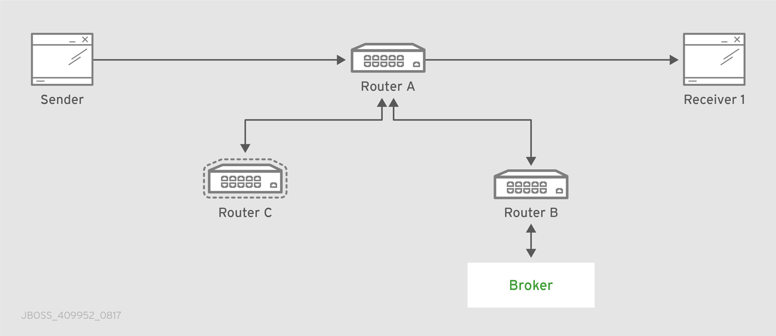
The "Router.A" configuration is something like following.
router {
    mode: interior
    id: Router.A
}
listener {
host: 0.0.0.0
port: 6000
authenticatePeer: no
}
connector {
name: INTER_ROUTER_B
addr: 127.0.0.1
port: 5001
role: inter-router
}
connector {
name: INTER_ROUTER_C
addr: 127.0.0.1
port: 5002
role: inter-router
}There is only one listener in order to accept client connections and two connector entities for connecting to the other two routers.
The "Router.B" configuration is the following.
router {
mode: interior
id: Router.B
}
listener {
addr: 0.0.0.0
port: 5001
authenticatePeer: no
role: inter-router
}
listener {
host: 0.0.0.0
port: 6001
authenticatePeer: no
}It has two listener entities in order to listen for connections from clients and from other routers in the network (in this case from the "Router.A" and "Router.C").
Finally, quite similar is the "Router.C" configuration.
router {
mode: interior
id: Router.C
}
listener {
addr: 0.0.0.0
port: 5002
authenticatePeer: no
role: inter-router
}
listener {
host: 0.0.0.0
port: 6002
authenticatePeer: no
}
connector {
name: INTER_ROUTER_B
addr: 127.0.0.1
port: 5001
role: inter-router
}It has two listener entities in order to listen for connections from clients and from other routers in the network (in this case from the "Router.A") and finally it has a connector (for connecting to the "Router.B")
Consider a sender client connected to "Router.A" and attached to my_address address which start to send messages (that is, 10 messages) and a receiver client connected to the "Router.B" and attached to the same address.
Starting the receiver, it waits for messages with no output on the console.
$ sudo python simple_recv.py -a localhost:6001/my_queue -m 10
Starting the sender, all the messages flow through "Router.A" and "Router.B" reaching the receiver; at this point the messages are all confirmed at sender side.
$ sudo python simple_send.py -a localhost:6001/my_queue -m 10 all messages confirmed
At same time, the receivers shows the messages received through the "Router.B".
{u'sequence': 1L}
{u'sequence': 2L}
{u'sequence': 3L}
{u'sequence': 4L}
{u'sequence': 5L}
{u'sequence': 6L}
{u'sequence': 7L}
{u'sequence': 8L}
{u'sequence': 9L}
{u'sequence': 10L}The path redundancy is provided by the other available path through the "Router.A", "Router.C" and then "Router.B". It means that if the connection between "Router.A" and "Router.B" goes down, the alternative path is used to reach the receiver.
Now, consider a fault on the "Router.B"; the receiver is not reachable anymore on that path but it can connect to the "Router.C" in order to continue to receive messages from the sender which does not know what’s happened and it can continue to send messages to the "Router.A" in order to reach the receiver.
Figure 7.2. Path Redundancy after Router Failure
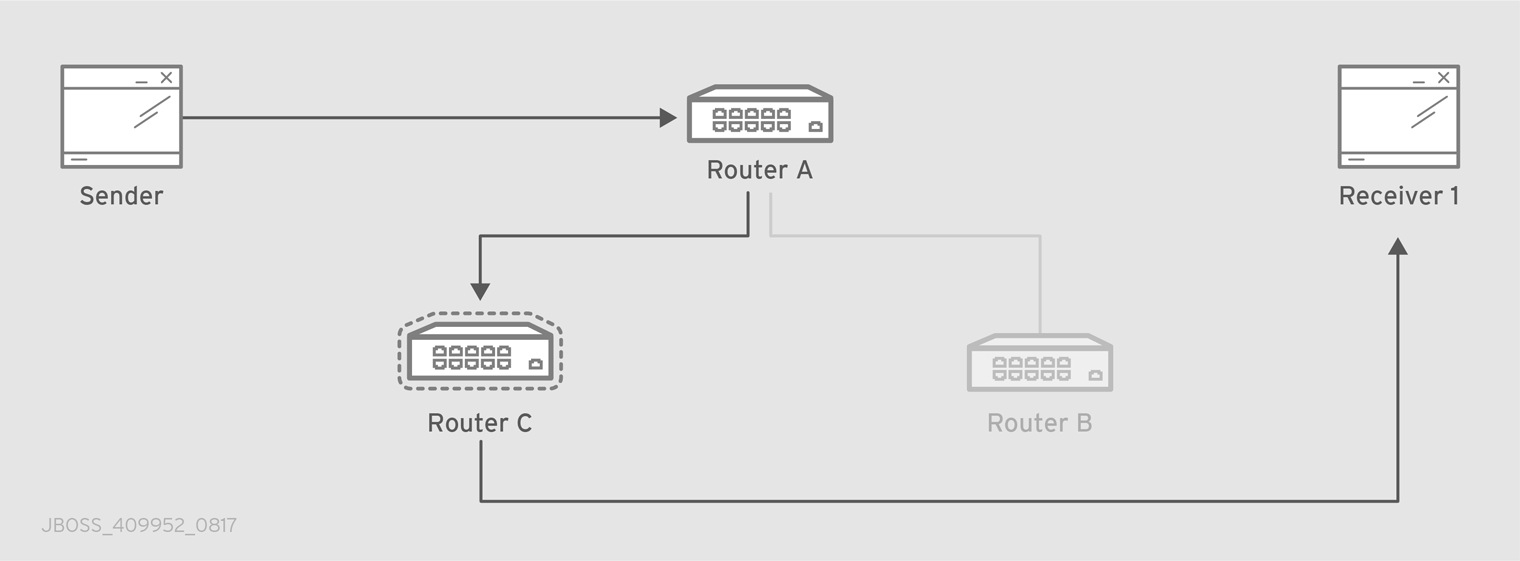
The receiver is still reachable in order to get messages from the sender as displayed in the console output.
$ sudo python simple_recv.py -a localhost:6002/my_queue -m 10
{u'sequence': 1L}
{u'sequence': 2L}
{u'sequence': 3L}
{u'sequence': 4L}
{u'sequence': 5L}
{u'sequence': 6L}
{u'sequence': 7L}
{u'sequence': 8L}
{u'sequence': 9L}
{u'sequence': 10L}7.2. Path Redundancy and Temporal Decoupling
In order to have temporal decoupling in a solution based on AMQ Interconnect, adding one or more brokers is a must for its "store and forward" feature. Choosing the right topology, it is possible to have a solution which offers reliability with both path redundancy and permanent storing for messages.
Consider the following simple scenario :
- a network with three routers "Router.A", "Router.B" and "Router.C" and finally a broker.
- the "Router.A" is connected to both "Router.B" and "Router.C".
- initially only the "Router.B" is connected to the broker.
- all three routers listen for client connections.
- a sender client connects to the "Router.A" in order to send messages to a queue in the broker.
- a receiver client connects to the "Router.A" in order to get messages from the queue in the broker.
Figure 7.3. Path Redundancy and Temporal Decoupling Enabled Topology
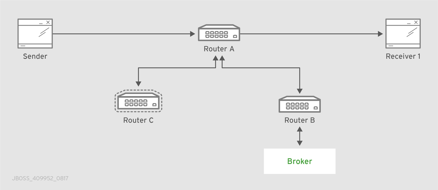
The receiver client can be offline when the sender starts to send messages because they’ll be stored into the queue permanently; coming back online, the receiver can get messages from the queue itself without message loss.
The "Router.A" configuration is something like following.
router {
    mode: interior
    id: Router.A
}

listener {
    host: 0.0.0.0
    port: 6000
    authenticatePeer: no
}

connector {
    name: INTER_ROUTER_B
    addr: 127.0.0.1
    port: 5001
    role: inter-router
}

connector {
    name: INTER_ROUTER_C
    addr: 127.0.0.1
    port: 5002
    role: inter-router
}
address {
prefix: my_queue
waypoint: yes
}
It has a listener for accepting incoming connections from clients and two connector entities in order to connect to the other routers. The queue named my_queue on the broker is exposed by a waypoint.
The "Router.B" configuration is the following.
router {
    mode: interior
    id: Router.B
}

listener {
    addr: 0.0.0.0
    port: 5001
    authenticatePeer: no
    role: inter-router
}

listener {
    host: 0.0.0.0
    port: 6001
    authenticatePeer: no
}
connector {
name: BROKER
addr: 127.0.0.1
port: 5672
role: route-container
}
address {
prefix: my_queue
waypoint: yes
}
autoLink {
address: my_queue
connection: BROKER
direction: in
}
autoLink {
address: my_queue
connection: BROKER
direction: out
}
It can accept incoming connections from clients and from other routers (in this case the "Router.A") and connects to the broker. The queue named my_queue on the broker is exposed by a waypoint with the related auto-links in both directions in order to send and receive messages to/from the queue itself.
Finally, the simple "Router.C" configuration.
router {
mode: interior
id: Router.C
}
listener {
addr: 0.0.0.0
port: 5002
authenticatePeer: no
role: inter-router
}
listener {
host: 0.0.0.0
port: 6002
authenticatePeer: no
}It can accept incoming connections from clients and from other routers (in this case the "Router.A"). Initially there is no connection between this router and the broker.
First of all, thanks to the broker and its "store and forward" feature, the sender can connect to the "Router.A" and start to send messages even if the receiver is not online in that moment. Using the Python sample from the Qpid Proton library, the console output is like following.
$ sudo python simple_send.py -a localhost:6000/my_queue -m 10 all messages confirmed
All messages are confirmed because they reached the queue inside the broker through "Router.A" and "Router.B"; it is confirmed using the qdstat tool.
$ sudo qdstat -b localhost:6001 -a Router Addresses class addr phs distrib in-proc local remote cntnr in out thru to-proc from-proc ================================================================================================================= local $_management_internal closest 1 0 0 0 0 0 0 0 0 local $displayname closest 1 0 0 0 0 0 0 0 0 mobile $management 0 closest 1 0 0 0 1 0 0 1 0 local $management closest 1 0 0 0 0 0 0 0 0 router Router.A closest 0 0 1 0 0 0 6 0 6 router Router.C closest 0 0 1 0 0 0 4 0 4 mobile my_queue 1 balanced 0 0 0 0 0 0 0 0 0 mobile my_queue 0 balanced 0 1 0 0 0 10 0 0 0 local qdhello flood 1 1 0 0 0 0 0 97 117 local qdrouter flood 1 0 0 0 0 0 0 7 0 topo qdrouter flood 1 0 2 0 0 0 8 13 9 local qdrouter.ma multicast 1 0 0 0 0 0 0 2 0 topo qdrouter.ma multicast 1 0 2 0 0 0 0 0 1 local temp.7f2u0zv9_U6QC5e closest 0 1 0 0 0 0 0 0 0
For the "Router.B", there are 10 messages as output (from the router to the broker) on the my_queue address.
Starting the receiver connected to the "Router.A", it gets all the available messages from the queue.
$ sudo python simple_recv.py -a localhost:6000/my_queue -m 10
{u'sequence': 1L}
{u'sequence': 2L}
{u'sequence': 3L}
{u'sequence': 4L}
{u'sequence': 5L}
{u'sequence': 6L}
{u'sequence': 7L}
{u'sequence': 8L}
{u'sequence': 9L}
{u'sequence': 10L}
Using the qdstat tool on the "Router.B" another time, the output is like following.
$ sudo qdstat -b localhost:6001 -a Router Addresses class addr phs distrib in-proc local remote cntnr in out thru to-proc from-proc ================================================================================================================= local $_management_internal closest 1 0 0 0 0 0 0 0 0 local $displayname closest 1 0 0 0 0 0 0 0 0 mobile $management 0 closest 1 0 0 0 2 0 0 2 0 local $management closest 1 0 0 0 0 0 0 0 0 router Router.A closest 0 0 1 0 0 0 6 0 6 router Router.C closest 0 0 1 0 0 0 4 0 4 mobile my_queue 1 balanced 0 0 0 0 10 0 10 0 0 mobile my_queue 0 balanced 0 1 0 0 0 10 0 0 0 local qdhello flood 1 1 0 0 0 0 0 156 182 local qdrouter flood 1 0 0 0 0 0 0 7 0 topo qdrouter flood 1 0 2 0 0 0 10 18 11 local qdrouter.ma multicast 1 0 0 0 0 0 0 2 0 topo qdrouter.ma multicast 1 0 2 0 0 0 0 2 1 local temp.Xov_ZUcyti3jjXY closest 0 1 0 0 0 0 0 0 0
For the "Router.B", there are 10 messages as input (from the broker to the router) on the my_queue address.
Now, consider a fault on the "Router.B"; in this case the broker is not reachable but it is possible to set up path redundancy through the "Router.C".
Figure 7.4. Path Redundancy and Temporal Decoupling after Router Failure
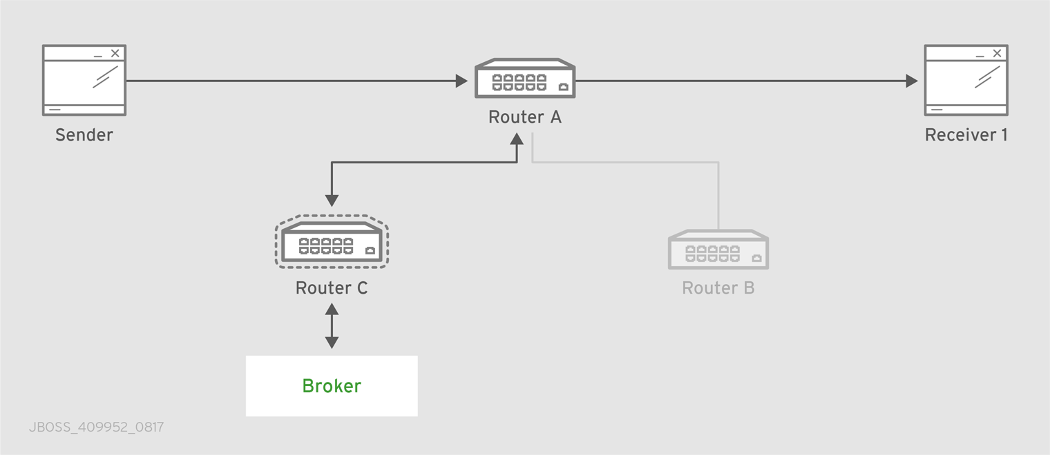
Using the qdmanage tool, it is possible to configure the waypoint on my_queue address, the related auto-links in both directions and finally the connector instance in order to enable the connection to the broker.
$ sudo qdmanage -b localhost:6002 create --stdin
[
{ "type":"connector", "name":"BROKER", "port":5672, "role":"route-container" },
{ "type":"address", "prefix":"my_queue", "waypoint":"yes" },
{ "type":"autoLink", "address":"my_queue", "connection":"BROKER", "direction":"in" },
{ "type":"autoLink", "address":"my_queue", "connection":"BROKER", "direction":"out" }
]
[
{
"verifyHostname": true,
"stripAnnotations": "both",
"name": "BROKER",
"allowRedirect": true,
"idleTimeoutSeconds": 16,
"maxFrameSize": 65536,
"host": "127.0.0.1",
"cost": 1,
"role": "route-container",
"maxSessions": 32768,
"type": "org.apache.qpid.dispatch.connector",
"port": "5672",
"identity": "connector/127.0.0.1:5672:BROKER",
"addr": "127.0.0.1"
},
{
"name": null,
"prefix": "my_queue",
"ingressPhase": 0,
"waypoint": false,
"distribution": "balanced",
"type": "org.apache.qpid.dispatch.router.config.address",
"identity": "7",
"egressPhase": 0
},
{
"address": "my_queue",
"name": null,
"linkRef": null,
"type": "org.apache.qpid.dispatch.router.config.autoLink",
"operStatus": "inactive",
"connection": "BROKER",
"direction": "in",
"phase": 1,
"lastError": null,
"externalAddress": null,
"identity": "8",
"containerId": null
},
{
"address": "my_queue",
"name": null,
"linkRef": null,
"type": "org.apache.qpid.dispatch.router.config.autoLink",
"operStatus": "inactive",
"connection": "BROKER",
"direction": "out",
"phase": 0,
"lastError": null,
"externalAddress": null,
"identity": "9",
"containerId": null
}
]
The "Router.C" configuration changes in the same way as "Router.B". It can accept incoming connections from clients and from other routers (in this case the "Router.A") and connects to the broker. The queue named my_queue on the broker is exposed by a waypoint with the related auto-links in both directions in order to send and receive messages to/from the queue itself.
At this point, the sender can connect to the "Router.A" for sending messages to the queue in the broker thanks to the "Router.C".
$ sudo python simple_send.py -a localhost:6000/my_queue -m 10
all messages confirmed
All messages are confirmed because they reached the queue inside the broker through "Router.A" and "Router.C"; it is confirmed using the qdstat tool.
$ sudo qdstat -b localhost:6002 -a Router Addresses class addr phs distrib in-proc local remote cntnr in out thru to-proc from-proc ================================================================================================================= local $_management_internal closest 1 0 0 0 0 0 0 1 1 local $displayname closest 1 0 0 0 0 0 0 0 0 mobile $management 0 closest 1 0 0 0 5 0 0 5 0 local $management closest 1 0 0 0 0 0 0 0 0 router Router.A closest 0 0 1 0 0 0 5 0 5 mobile my_queue 0 balanced 0 1 0 0 0 10 0 0 0 mobile my_queue 1 balanced 0 0 0 0 0 0 0 0 0 local qdhello flood 1 1 0 0 0 0 0 665 647 local qdrouter flood 1 0 0 0 0 0 0 8 0 topo qdrouter flood 1 0 1 0 0 0 31 52 32 local qdrouter.ma multicast 1 0 0 0 0 0 0 1 0 topo qdrouter.ma multicast 1 0 1 0 0 0 1 2 1 local temp.k6UMaS4P0JmtSlL closest 0 1 0 0 0 0 0 0 0
For the "Router.C", there are 10 messages as output (from the router to the broker) on the my_queue address.
Starting the receiver connected to the "Router.A", it gets all the available messages from the queue.
$ sudo python simple_recv.py -a localhost:6000/my_queue -m 10
{u'sequence': 1L}
{u'sequence': 2L}
{u'sequence': 3L}
{u'sequence': 4L}
{u'sequence': 5L}
{u'sequence': 6L}
{u'sequence': 7L}
{u'sequence': 8L}
{u'sequence': 9L}
{u'sequence': 10L}
Using the qdstat tool on the "Router.C" another time, the output is like following.
$ sudo qdstat -b localhost:6002 -a Router Addresses class addr phs distrib in-proc local remote cntnr in out thru to-proc from-proc ================================================================================================================= local $_management_internal closest 1 0 0 0 0 0 0 1 1 local $displayname closest 1 0 0 0 0 0 0 0 0 mobile $management 0 closest 1 0 0 0 6 0 0 6 0 local $management closest 1 0 0 0 0 0 0 0 0 router Router.A closest 0 0 1 0 0 0 5 0 5 mobile my_queue 0 balanced 0 1 0 0 0 10 0 0 0 mobile my_queue 1 balanced 0 0 0 0 10 0 10 0 0 local qdhello flood 1 1 0 0 0 0 0 746 726 local qdrouter flood 1 0 0 0 0 0 0 8 0 topo qdrouter flood 1 0 1 0 0 0 34 55 35 local qdrouter.ma multicast 1 0 0 0 0 0 0 1 0 topo qdrouter.ma multicast 1 0 1 0 0 0 1 4 1 local temp.Hso3moy3l+Sn+Fy closest 0 1 0 0 0 0 0 0 0
For the "Router.C", there are 10 messages as input (from the broker to the router) on the my_queue address.
7.3. Sharded Queue
Every broker has limits in terms of queue size but in order to overcome this problem, one possible solution is "sharding" queues : in that way a single queue is divided in more "shards" (chunks) each on a different broker. It means that such solution needs more than one broker instance in order to host a shard on each of them. Of course, a sender connected to one of these brokers can send messages to the shard hosted only on that broker. At same time, a receiver connected to a broker can get messages from the shard that is hosted on that broker and can not see available messages in the shards hosted on the other brokers, even if they are all parts of the same queue.
Even if speaking about shards it is obvious that they are real queues all with same name but on different brokers. The "shard" concept is an abstract one because finally a shard is a real queue stored on a broker.
The big problem in this scenario, designed only with brokers, is that a receiver can be stucked on an empty shard without reading any messages while the shards on the other brokers have messages to deliver. it is a real problem because the receiver is interested in receiving messages from the whole queue and it does not take care if it is shared or not. Because of this problem, the receiver sees the queue as empty even if it is not so true due to the sharding and the messages available on the other shards.
The above problem can be solved adding a AMQ Interconnect instance in the network in front of the brokers and leverage on its waypoint feature with related auto-links.
Consider the following simple scenario :
- a network with one router "Router.A" and two brokers.
- the "Router.A" listens for clients connections and it is connected to both brokers.
- the brokers host shards for a queue; each broker has one shard.
- a sender client connects to the "Router.A" in order to send messages to the queue.
- a receiver client connects to the "Router.A" in order to get messages from the queue.
Figure 7.5. Sharded Queue Enabled Topology
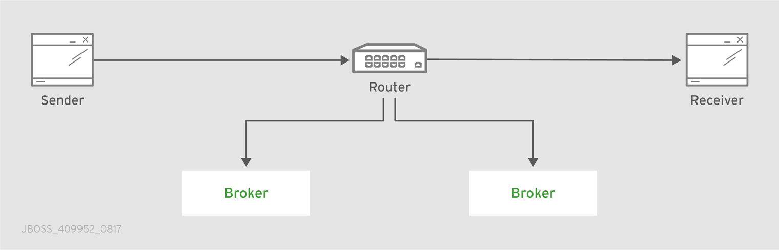
With such solution and connecting to the "Router.A", sender and receiver do not know anything about sharding; they want send and receive messages to/from the whole queue that is the only thing they are aware of. They are both connected to the router and see only one address (related to the queue).
The "Router.A" configuration is something like following.
router {
mode: standalone
id: Router.A
}
listener {
host: 0.0.0.0
port: 6000
authenticatePeer: no
}
connector {
name: BROKER1
addr: 127.0.0.1
port: 5672
role: route-container
}
connector {
name: BROKER2
addr: 127.0.0.1
port: 5673
role: route-container
}
address {
prefix: my_queue
waypoint: yes
}
autoLink {
address: my_queue
connection: BROKER1
direction: in
}
autoLink {
address: my_queue
connection: BROKER1
direction: out
}
autoLink {
address: my_queue
connection: BROKER2
direction: in
}
autoLink {
address: my_queue
connection: BROKER2
direction: out
}
The router has a listener for incoming connection from clients and two connector instances in order to connect to both brokers. The whole queue is named my_queue hosted in terms of shards on both brokers and the router is configured with a waypoint for that address. Finally, there are two auto-links in both directions for that queue on both brokers.
Using the Python sample from the Qpid Proton library, the sender can connect to the "Router.A" and start to send messages to the queue; the console output is like following.
$ sudo python simple_send.py -a localhost:6000/my_queue -m 10
all messages confirmed
All messages are confirmed because they reached the queue and, thanks to the default balanced distribution on the address, the messages are delivered to both shards on the brokers (5 messages per shard). Using the qdstat tool on the router, the distribution is clear.
$ sudo qdstat -b localhost:6000 -l Router Links type dir conn id id peer class addr phs cap undel unsettled deliveries admin oper ======================================================================================================================= endpoint in 1 6 mobile my_queue 1 250 0 0 0 enabled up endpoint out 1 7 mobile my_queue 0 250 0 0 5 enabled up endpoint in 2 8 mobile my_queue 1 250 0 0 0 enabled up endpoint out 2 9 mobile my_queue 0 250 0 0 5 enabled up endpoint in 8 19 mobile $management 0 250 0 0 1 enabled up endpoint out 8 20 local temp.qCGHruCa4UIvYrS 250 0 0 0 enabled up
There are the out links (from router to brokers) for the my_queue address (id values 7 and 9) which have each 5 deliveries. It shows messages distributed across brokers and related shards for the queue; it is confirmed by the different connections they are tied (conn id values 1 and 2).
Starting the receiver connected to the "Router.A", it gets all the available messages from the queue.
$ sudo python simple_recv.py -a localhost:6000/my_queue -m 10
{u'sequence': 1L}
{u'sequence': 2L}
{u'sequence': 3L}
{u'sequence': 4L}
{u'sequence': 5L}
{u'sequence': 6L}
{u'sequence': 7L}
{u'sequence': 8L}
{u'sequence': 9L}
{u'sequence': 10L}
As for the sender, they are received through both the brokers and related shards. it is confirmed using the qdstat tool.
$ sudo qdstat -b localhost:6000 -l
Router Links
  type      dir  conn id  id  peer  class   addr                  phs  cap  undel  unsettled  deliveries  admin    oper
  =======================================================================================================================
  endpoint  in   1        6         mobile  my_queue              1    250  0      0          5           enabled  up
  endpoint  out  1        7         mobile  my_queue              0    250  0      0          5           enabled  up
  endpoint  in   2        8         mobile  my_queue              1    250  0      0          5           enabled  up
  endpoint  out  2        9         mobile  my_queue              0    250  0      0          5           enabled  up
  endpoint  in   10       22        mobile  $management           0    250  0      0          1           enabled  up
  endpoint  out  10       23        local   temp.HT+f3ZilGP5o3wo       250  0      0          0           enabled  up
There are the in links (from brokers to router) for the my_queue address (id values 6 and 8) which have each 5 deliveries. It shows messages distributed across brokers and related shards for the queue; it is confirmed by the different connections they are tied (conn id values 1 and 2).
One disadvantage of sharded queues is that the receiver might receive messages "out of order" even with very good performance.
Appendix A. Using Cyrus SASL to Provide Authentication
AMQ Interconnect uses the Cyrus SASL library for SASL authentication. Therefore, if you want to use SASL, you must set up the Cyrus SASL database and configure it.
A.1. Generating a SASL Database
To generate a SASL database to store credentials, enter the following command:
$ sudo saslpasswd2 -c -f SASL_DATABASE_NAME.sasldb -u DOMAIN_NAME USER_NAME
This command creates or updates the specified SASL database, and adds the specified user name to it. The command also prompts you for the user name’s password.
The full user name is the user name you entered plus the domain name (USER_NAME@DOMAIN_NAME). Providing a domain name is not required when you add a user to the database, but if you do not provide one, a default domain will be added automatically (the hostname of the machine on which the tool is running). For example, in the command above, the full user name would be user1@domain.com.
A.2. Viewing Users in a SASL Database
To view the user names stored in the SASL database:
$ sudo sasldblistusers2 -f qdrouterd.sasldb
user2@domain.com: PASSWORD
user1@domain.com: PASSWORD
A.3. Configuring a SASL Database
To use the SASL database to provide authentication in AMQ Interconnect:
-
Open the
/etc/sasl2/qdrouterd.confconfiguration file. Set the following attributes:
pwcheck_method: auxprop
auxprop_plugin: sasldb
sasldb_path: SASL_DATABASE_NAME
mech_list: MECHANISM1 ...
sasldb_pathThe name of the SASL database to use.
For example:
sasldb_path: qdrouterd.sasldb
mech_listThe SASL mechanisms to enable for authentication. To add multiple mechanisms, separate each entry with a space.
For example:
mech_list: ANONYMOUS DIGEST-MD5 EXTERNAL PLAIN
Appendix B. Using your subscription
AMQ is provided through a software subscription. To manage your subscriptions, access your account at the Red Hat Customer Portal.
Accessing your account
- Go to access.redhat.com.
- If you do not already have an account, create one.
- Log in to your account.
Activating a subscription
- Go to access.redhat.com.
- Navigate to My Subscriptions.
- Navigate to Activate a subscription and enter your 16-digit activation number.
Downloading ZIP and TAR files
To access ZIP or TAR files, use the customer portal to find the relevant files for download. If you are using RPM packages, this step is not required.
- Open a browser and log in to the Red Hat Customer Portal Product Downloads page at access.redhat.com/downloads.
- Locate the Red Hat AMQ entries in the JBOSS INTEGRATION AND AUTOMATION category.
- Select the desired AMQ product. The Software Downloads page opens.
- Click the Download link for your component.
Registering your system for packages
To install RPM packages on Red Hat Enterprise Linux, your system must be registered. If you are using ZIP or TAR files, this step is not required.
- Go to access.redhat.com.
- Navigate to Registration Assistant.
- Select your OS version and continue to the next page.
- Use the listed command in your system terminal to complete the registration.
To learn more see How to Register and Subscribe a System to the Red Hat Customer Portal.
Revised on 2019-08-09 18:13:29 UTC