
Virtualization
OpenShift Virtualization installation, usage, and release notes
Abstract
Chapter 1. About OpenShift Virtualization
Learn about OpenShift Virtualization’s capabilities and support scope.
1.1. What you can do with OpenShift Virtualization
OpenShift Virtualization is an add-on to OpenShift Container Platform that allows you to run and manage virtual machine workloads alongside container workloads.
OpenShift Virtualization adds new objects into your OpenShift Container Platform cluster by using Kubernetes custom resources to enable virtualization tasks. These tasks include:
- Creating and managing Linux and Windows virtual machines (VMs)
- Running pod and VM workloads alongside each other in a cluster
- Connecting to virtual machines through a variety of consoles and CLI tools
- Importing and cloning existing virtual machines
- Managing network interface controllers and storage disks attached to virtual machines
- Live migrating virtual machines between nodes
An enhanced web console provides a graphical portal to manage these virtualized resources alongside the OpenShift Container Platform cluster containers and infrastructure.
OpenShift Virtualization is designed and tested to work well with Red Hat OpenShift Data Foundation features.
When you deploy OpenShift Virtualization with OpenShift Data Foundation, you must create a dedicated storage class for Windows virtual machine disks. See Optimizing ODF PersistentVolumes for Windows VMs for details.
You can use OpenShift Virtualization with the OVN-Kubernetes, OpenShift SDN, or one of the other certified network plugins listed in Certified OpenShift CNI Plug-ins.
You can check your OpenShift Virtualization cluster for compliance issues by installing the Compliance Operator and running a scan with the ocp4-moderate and ocp4-moderate-node profiles. The Compliance Operator uses OpenSCAP, a NIST-certified tool, to scan and enforce security policies.
1.1.1. OpenShift Virtualization supported cluster version
OpenShift Virtualization 4.13 is supported for use on OpenShift Container Platform 4.13 clusters. To use the latest z-stream release of OpenShift Virtualization, you must first upgrade to the latest version of OpenShift Container Platform.
1.2. About storage volumes for virtual machine disks
If you use the storage API with known storage providers, volume and access modes are selected automatically. However, if you use a storage class that does not have a storage profile, you must select the volume and access mode.
For best results, use accessMode: ReadWriteMany and volumeMode: Block. This is important for the following reasons:
- The ReadWriteMany (RWX) access mode is required for live migration.
The
Blockvolume mode performs significantly better in comparison to theFilesystemvolume mode. This is because theFilesystemvolume mode uses more storage layers, including a file system layer and a disk image file. These layers are not necessary for VM disk storage.For example, if you use Red Hat OpenShift Data Foundation, Ceph RBD volumes are preferable to CephFS volumes.
ImportantYou cannot live migrate virtual machines that use:
- A storage volume with ReadWriteOnce (RWO) access mode
- Passthrough features such as GPUs
Do not set the
evictionStrategyfield toLiveMigratefor these virtual machines.
1.3. Single-node OpenShift differences
You can install OpenShift Virtualization on single-node OpenShift.
However, you should be aware that Single-node OpenShift does not support the following features:
- High availability
- Pod disruption
- Live migration
- Virtual machines or templates that have an eviction strategy configured
1.4. Additional resources
Chapter 2. OpenShift Virtualization architecture
Learn about OpenShift Virtualization architecture.
2.1. How OpenShift Virtualization architecture works
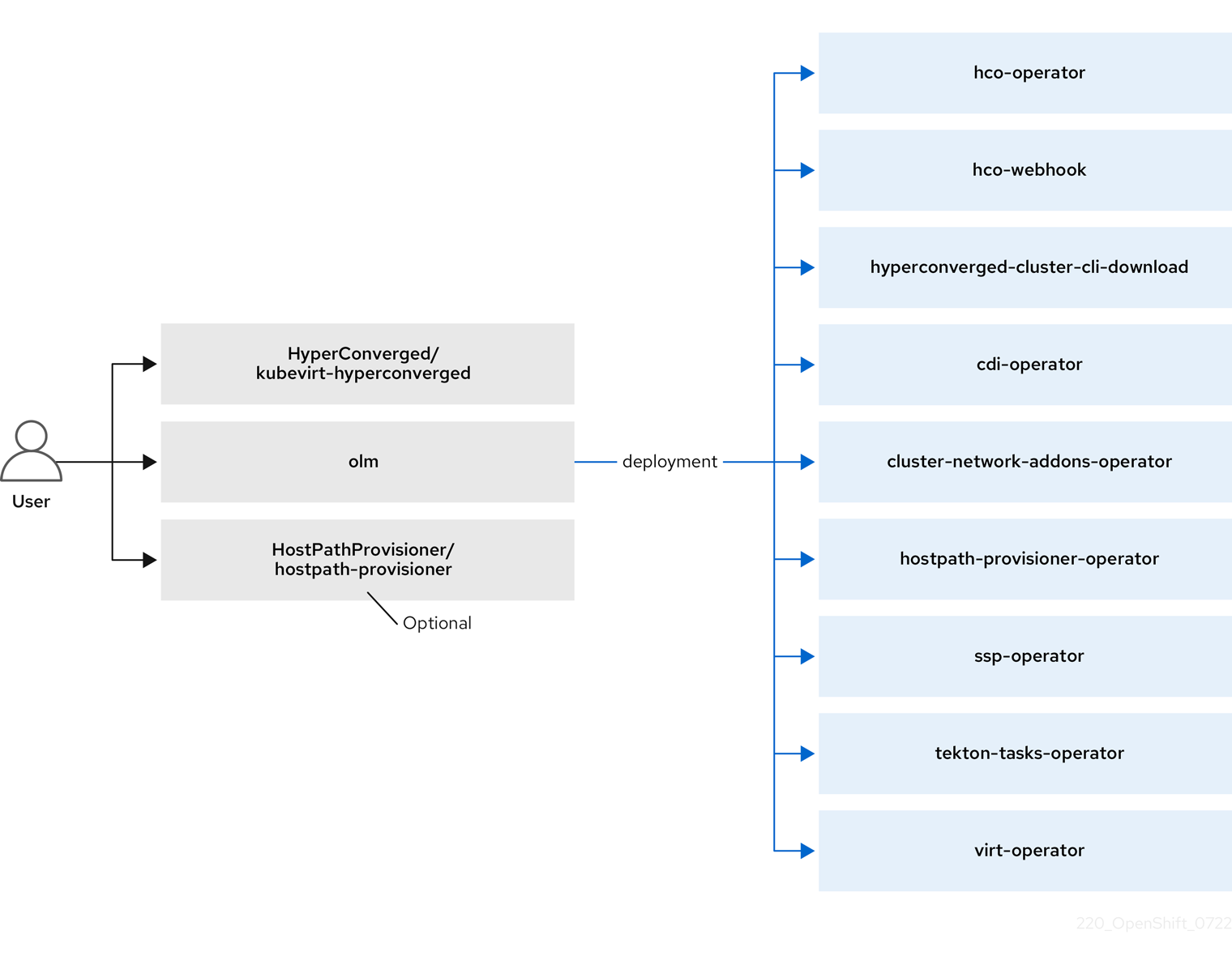
After you install OpenShift Virtualization, the Operator Lifecycle Manager (OLM) deploys operator pods for each component of OpenShift Virtualization:
-
Compute:
virt-operator -
Storage:
cdi-operator -
Network:
cluster-network-addons-operator -
Scaling:
ssp-operator -
Templating:
tekton-tasks-operator
OLM also deploys the hyperconverged-cluster-operator pod, which is responsible for the deployment, configuration, and life cycle of other components, and several helper pods: hco-webhook, and hyperconverged-cluster-cli-download.
After all operator pods are successfully deployed, you should create the HyperConverged custom resource (CR). The configurations set in the HyperConverged CR serve as the single source of truth and the entrypoint for OpenShift Virtualization, and guide the behavior of the CRs.
The HyperConverged CR creates corresponding CRs for the operators of all other components within its reconciliation loop. Each operator then creates resources such as daemon sets, config maps, and additional components for the OpenShift Virtualization control plane. For example, when the hco-operator creates the KubeVirt CR, the virt-operator reconciles it and create additional resources such as virt-controller, virt-handler, and virt-api.
The OLM deploys the hostpath-provisioner-operator, but it is not functional until you create a hostpath provisioner (HPP) CR.
Additional resources
2.2. About the hco-operator
The hco-operator (HCO) provides a single entry point for deploying and managing OpenShift Virtualization and several helper operators with opinionated defaults. It also creates custom resources (CRs) for those operators.
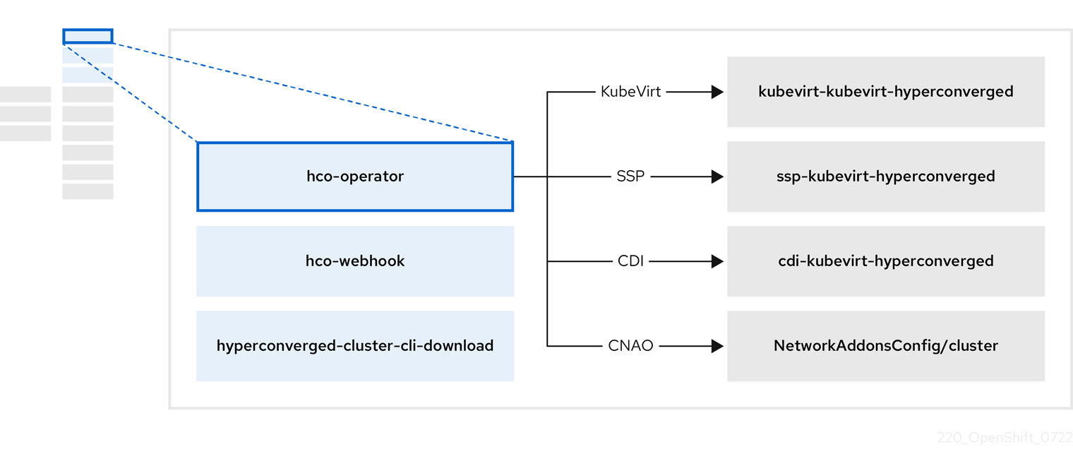
Table 2.1. hco-operator components
| Component | Description |
|---|---|
|
|
Validates the |
|
|
Provides the |
|
| Contains all operators, CRs, and objects needed by OpenShift Virtualization. |
|
| An SSP CR. This is automatically created by the HCO. |
|
| A CDI CR. This is automatically created by the HCO. |
|
|
A CR that instructs and is managed by the |
2.3. About the cdi-operator
The cdi-operator manages the Containerized Data Importer (CDI), and its related resources, which imports a virtual machine (VM) image into a persistent volume claim (PVC) by using a data volume.
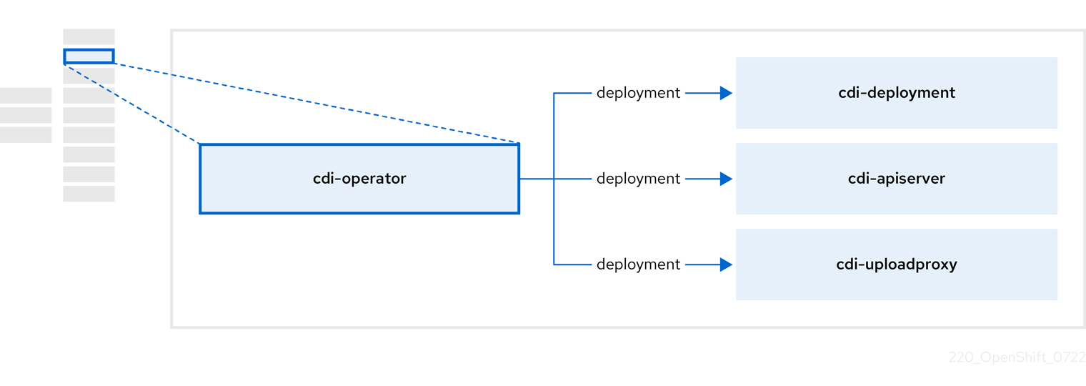
Table 2.2. cdi-operator components
| Component | Description |
|---|---|
|
| Manages the authorization to upload VM disks into PVCs by issuing secure upload tokens. |
|
| Directs external disk upload traffic to the appropriate upload server pod so that it can be written to the correct PVC. Requires a valid upload token. |
|
| Helper pod that imports a virtual machine image into a PVC when creating a data volume. |
2.4. About the cluster-network-addons-operator
The cluster-network-addons-operator deploys networking components on a cluster and manages the related resources for extended network functionality.
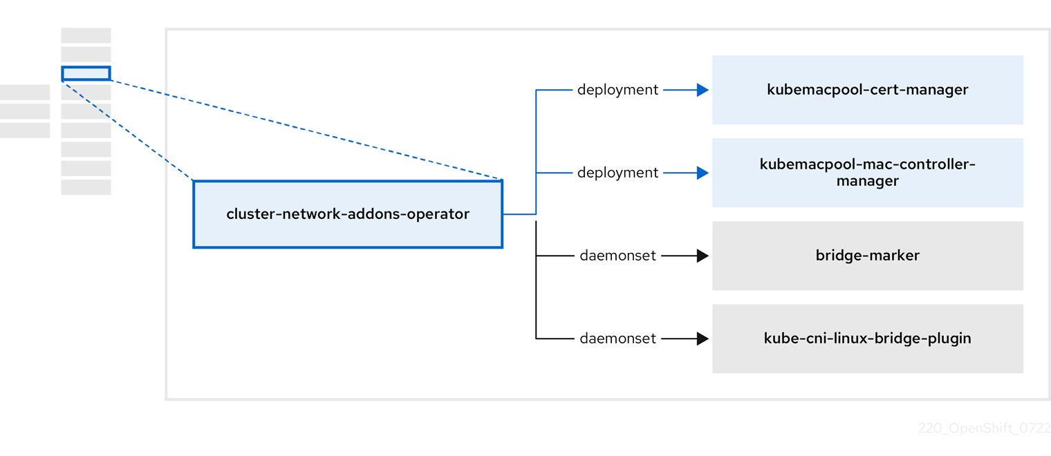
Table 2.3. cluster-network-addons-operator components
| Component | Description |
|---|---|
|
| Manages TLS certificates of Kubemacpool’s webhooks. |
|
| Provides a MAC address pooling service for virtual machine (VM) network interface cards (NICs). |
|
| Marks network bridges available on nodes as node resources. |
|
| Installs CNI plugins on cluster nodes, enabling the attachment of VMs to Linux bridges through network attachment definitions. |
2.5. About the hostpath-provisioner-operator
The hostpath-provisioner-operator deploys and manages the multi-node hostpath provisioner (HPP) and related resources.
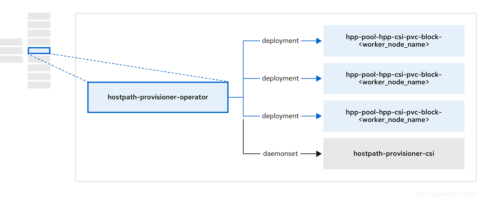
Table 2.4. hostpath-provisioner-operator components
| Component | Description |
|---|---|
|
| Provides a worker for each node where the hostpath provisioner (HPP) is designated to run. The pods mount the specified backing storage on the node. |
|
| Implements the Container Storage Interface (CSI) driver interface of the HPP. |
|
| Implements the legacy driver interface of the HPP. |
2.6. About the ssp-operator
The ssp-operator deploys the common templates, the related default boot sources, and the template validator.
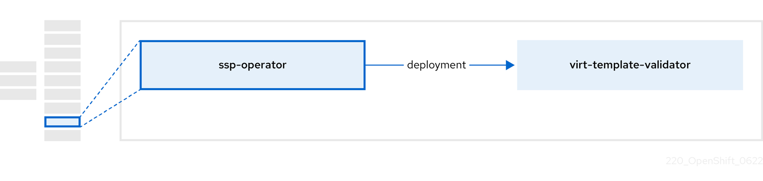
Table 2.5. ssp-operator components
| Component | Description |
|---|---|
|
|
Checks |
2.7. About the tekton-tasks-operator
The tekton-tasks-operator deploys example pipelines showing the usage of OpenShift Pipelines for VMs. It also deploys additional OpenShift Pipeline tasks that allow users to create VMs from templates, copy and modify templates, and create data volumes.
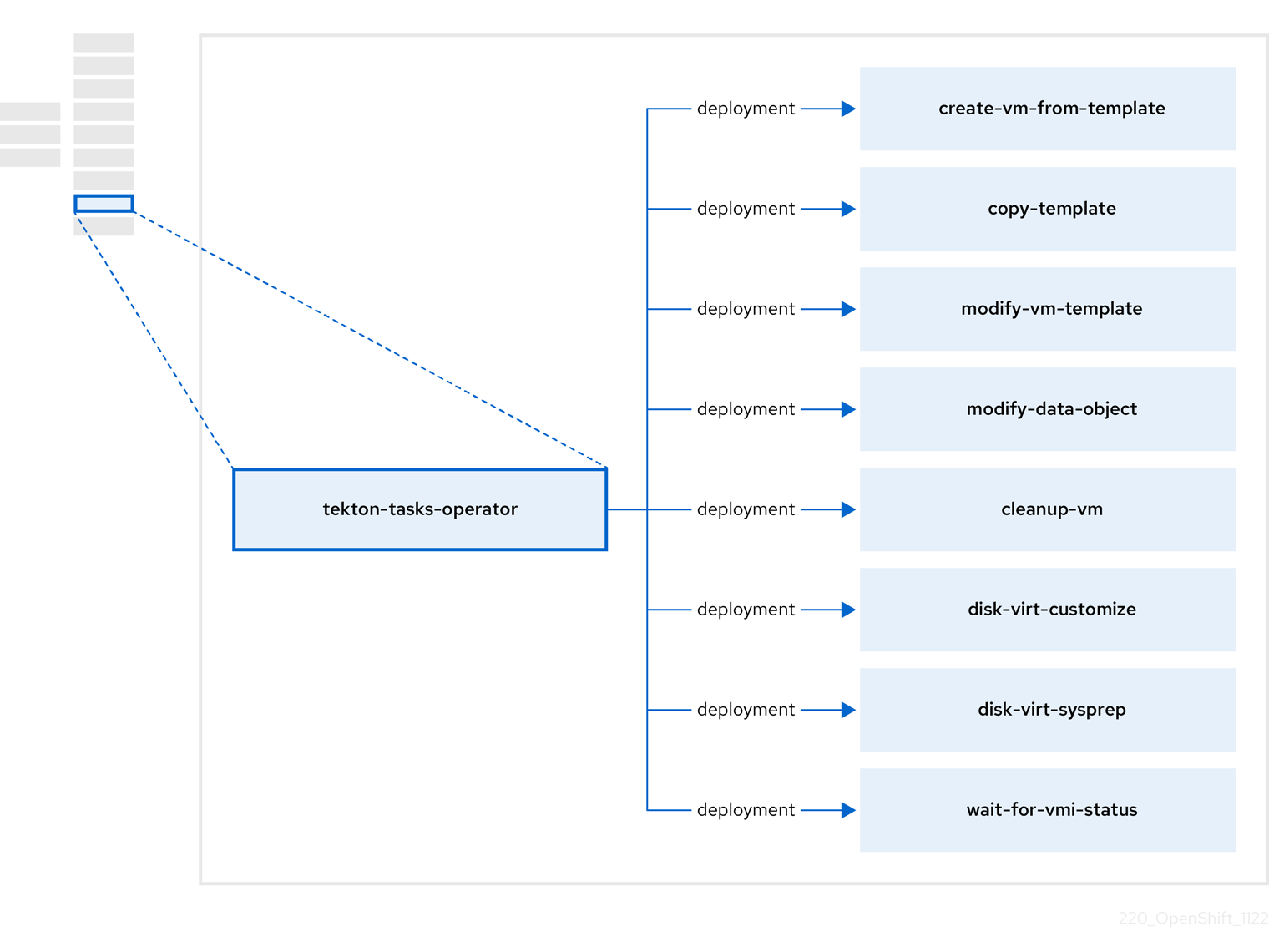
Table 2.6. tekton-tasks-operator components
| Component | Description |
|---|---|
|
| Creates a VM from a template. |
|
| Copies a VM template. |
|
| Creates or removes a VM template. |
|
| Creates or removes data volumes or data sources. |
|
| Runs a script or a command on a VM, then stops or deletes the VM afterward. |
|
|
Runs a |
|
|
Runs a |
|
| Waits for a specific VMI status, then fails or succeeds according to that status. |
2.8. About the virt-operator
The virt-operator deploys, upgrades, and manages OpenShift Virtualization without disrupting current virtual machine (VM) workloads.
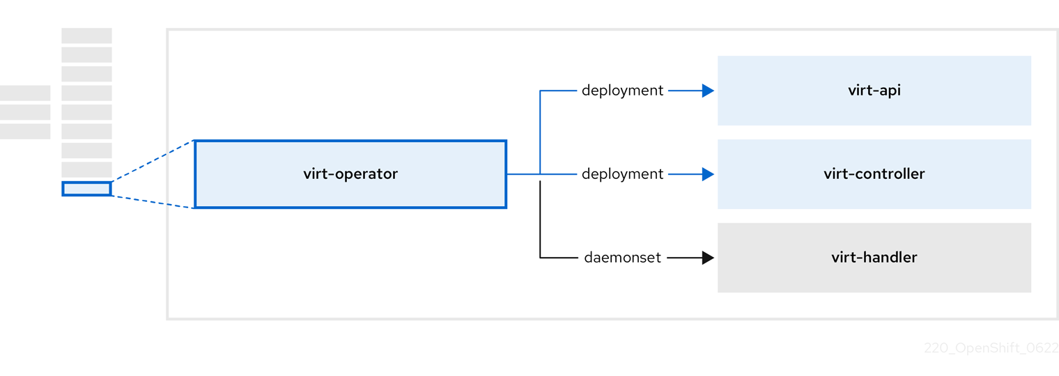
Table 2.7. virt-operator components
| Component | Description |
|---|---|
|
| HTTP API server that serves as the entry point for all virtualization-related flows. |
|
|
Observes the creation of a new VM instance object and creates a corresponding pod. When the pod is scheduled on a node, |
|
|
Monitors any changes to a VM and instructs |
|
|
Contains the VM that was created by the user as implemented by |
Chapter 3. Getting started with OpenShift Virtualization
You can explore the features and functionalities of OpenShift Virtualization by installing and configuring a basic environment.
Cluster configuration procedures require cluster-admin privileges.
3.1. Planning and installing OpenShift Virtualization
Plan and install OpenShift Virtualization on an OpenShift Container Platform cluster:
Planning and installation resources
3.2. Creating and managing virtual machines
Create virtual machines (VMs) by using the web console:
Connect to VMs:
- Connect to the serial console or VNC console of a VM by using the web console.
- Connect to a VM by using SSH.
- Connect to a Windows VM by using RDP.
Manage VMs:
3.3. Next steps
Connect the VMs to secondary networks:
- Connect a VM to a Linux bridge network.
Connect a VM to an SR-IOV network.
NoteVMs are connected to the pod network by default. You must configure a secondary network, such as Linux bridge or SR-IOV, and then add the network to the VM configuration.
- Live migrate VMs.
- Back up and restore VMs.
- Tune and scale your cluster
Chapter 4. Web console overview
The Virtualization section of the OpenShift Container Platform web console contains the following pages for managing and monitoring your OpenShift Virtualization environment.
Table 4.1. Virtualization pages
| Page | Description |
|---|---|
| Manage and monitor the OpenShift Virtualization environment. | |
| Create VirtualMachines from a catalog of templates. | |
| Configure and monitor VirtualMachines. | |
| Create and manage templates. | |
| Create and manage DataSources for VirtualMachine boot sources. | |
| Create and manage MigrationPolicies for workloads. |
Table 4.2. Key
| Icon | Description |
|---|---|
|
| Edit icon |
|
| Link icon |
4.1. Overview page
The Overview page displays resources, metrics, migration progress, and cluster-level settings.
Example 4.1. Overview page
| Element | Description |
|---|---|
|
Download virtctl |
Download the |
| Resources, usage, alerts, and status | |
| Top consumers of CPU, memory, and storage resources | |
| Status of live migrations | |
| Cluster-wide settings, including live migration limits and user permissions |
4.1.1. Overview tab
The Overview tab displays resources, usage, alerts, and status.
Example 4.2. Overview tab
| Element | Description |
|---|---|
| Getting started resources card |
|
| VirtualMachines tile | Number of VirtualMachines, with a chart showing the last 7 days' trend |
| vCPU usage tile | vCPU usage, with a chart showing the last 7 days' trend |
| Memory tile | Memory usage, with a chart showing the last 7 days' trend |
| Storage tile | Storage usage, with a chart showing the last 7 days' trend |
| Alerts tile | OpenShift Virtualization alerts, grouped by severity |
| VirtualMachine statuses tile | Number of VirtualMachines, grouped by status |
| VirtualMachines per template chart | Number of VirtualMachines created from templates, grouped by template name |
4.1.2. Top consumers tab
The Top consumers tab displays the top consumers of CPU, memory, and storage.
Example 4.3. Top consumers tab
| Element | Description |
|---|---|
|
View virtualization dashboard | Link to Observe → Dashboards, which displays the top consumers for OpenShift Virtualization |
| Time period list | Select a time period to filter the results. |
| Top consumers list | Select the number of top consumers to filter the results. |
| CPU chart | VirtualMachines with the highest CPU usage |
| Memory chart | VirtualMachines with the highest memory usage |
| Memory swap traffic chart | VirtualMachines with the highest memory swap traffic |
| vCPU wait chart | VirtualMachines with the highest vCPU wait periods |
| Storage throughput chart | VirtualMachines with the highest storage throughput usage |
| Storage IOPS chart | VirtualMachines with the highest storage input/output operations per second usage |
4.1.3. Migrations tab
The Migrations tab displays the status of VirtualMachineInstance migrations.
Example 4.4. Migrations tab
| Element | Description |
|---|---|
| Time period list | Select a time period to filter VirtualMachineInstanceMigrations. |
| VirtualMachineInstanceMigrations table | List of VirtualMachineInstance migrations |
4.1.4. Settings tab
The Settings tab displays cluster-wide settings on the following tabs:
Table 4.3. Tabs on Settings tab
| Tab | Description |
|---|---|
| OpenShift Virtualization version and update status | |
| Live migration limits and network settings | |
| Project for Red Hat templates | |
| Cluster-wide user permissions |
4.1.4.1. General tab
The General tab displays the OpenShift Virtualization version and update status.
Example 4.5. General tab
| Label | Description |
|---|---|
| Service name | OpenShift Virtualization |
| Provider | Red Hat |
| Installed version | 4.13.8 |
| Update status |
Example: |
| Channel | Channel selected for updates |
4.1.4.2. Live migration tab
You can configure live migration on the Live migration tab.
Example 4.6. Live migration tab
| Element | Description |
|---|---|
| Max. migrations per cluster field | Select the maximum number of live migrations per cluster. |
| Max. migrations per node field | Select the maximum number of live migrations per node. |
| Live migration network list | Select a dedicated secondary network for live migration. |
4.1.4.3. Templates project tab
You can select a project for templates on the Templates project tab.
Example 4.7. Templates project tab
| Element | Description |
|---|---|
| Project list |
Select a project in which to store Red Hat templates. The default template project is If you want to define multiple template projects, you must clone the templates on the Templates page for each project. |
4.1.4.4. User permissions tab
The User permissions tab displays cluster-wide user permissions for tasks.
Example 4.8. User permissions tab
| Element | Description |
|---|---|
| User permissions table | List of tasks, such as Share templates, and permissions |
4.2. Catalog page
You can create a VirtualMachine by selecting a template or boot source on the Catalog page.
Example 4.9. Catalog page
| Element | Description |
|---|---|
| Select a template to create a VirtualMachine from. |
4.2.1. Template catalog tab
| Element | Description |
|---|---|
| Template project list | Select the project in which your templates are located.
By default, Red Hat templates are stored in the |
| All items|Default templates | Click Default templates to display only default templates. |
| Boot source available checkbox | Select the checkbox to display templates with an available boot source. |
| Operating system checkboxes | Select checkboxes to display templates with selected operating systems. |
| Workload checkboxes | Select checkboxes to display templates with selected workloads. |
| Search field | Search templates by keyword. |
| Template tiles | Click a template tile to view template details and to create a VirtualMachine. |
4.3. VirtualMachines page
You can create and manage VirtualMachines on the VirtualMachines page.
Example 4.10. VirtualMachines page
| Element | Description |
|---|---|
| Create → From template | Create a VirtualMachine on the Catalog page → Template catalog tab. |
| Create → From YAML | Create a VirtualMachine by editing a YAML configuration file. |
| Filter field | Filter VirtualMachines by status, template, operating system, or node. |
| Search field | Search for VirtualMachines by name or by label. |
| VirtualMachines table | List of VirtualMachines
Click the Options menu
Click a VirtualMachine to navigate to the VirtualMachine details page. |
4.3.1. VirtualMachine details page
You can configure a VirtualMachine on the VirtualMachine details page.
Example 4.11. VirtualMachine details page
| Element | Description |
|---|---|
| Actions menu | Click the Actions menu to select Stop, Restart, Pause, Clone, Migrate, Copy SSH command, Edit labels, Edit annotations, or Delete. |
| Resource usage, alerts, disks, and devices | |
| VirtualMachine details and configurations | |
| Memory, CPU, storage, network, and migration metrics | |
| VirtualMachine YAML configuration file | |
| Contains the Scheduling, Environment, Network interfaces, Disks, and Scripts tabs | |
| Scheduling a VirtualMachine to run on specific nodes | |
| Config map, secret, and service account management | |
| Network interfaces | |
| Disks | |
| Cloud-init settings, SSH key for Linux VirtualMachines, Sysprep answer file for Windows VirtualMachines | |
| VirtualMachine event stream | |
| Console session management | |
| Snapshot management | |
| Status conditions and volume snapshot status |
4.3.1.1. Overview tab
The Overview tab displays resource usage, alerts, and configuration information.
Example 4.12. Overview tab
| Element | Description |
|---|---|
| Details tile | General VirtualMachine information |
| Utilization tile | CPU, Memory, Storage, and Network transfer charts. By default, Network transfer displays the sum of all networks. To view the breakdown for a specific network, click Breakdown by network. |
| Hardware devices tile | GPU and host devices |
| Alerts tile | OpenShift Virtualization alerts, grouped by severity |
| Snapshots tile |
Take snapshot |
| Network interfaces tile | Network interfaces table |
| Disks tile | Disks table |
4.3.1.2. Details tab
You can view information about the VirtualMachine and edit labels, annotations, and other metadata and on the Details tab.
Example 4.13. Details tab
| Element | Description |
|---|---|
| YAML switch | Set to ON to view your live changes in the YAML configuration file. |
| Name | VirtualMachine name |
| Namespace | VirtualMachine namespace |
| Labels | Click the edit icon to edit the labels. |
| Annotations | Click the edit icon to edit the annotations. |
| Description | Click the edit icon to enter a description. |
| Operating system | Operating system name |
| CPU|Memory | Click the edit icon to edit the CPU|Memory request.
The number of CPUs is calculated by using the following formula: |
| Machine type | VirtualMachine machine type |
| Boot mode | Click the edit icon to edit the boot mode. |
| Start in pause mode | Click the edit icon to enable this setting. |
| Template | Name of the template used to create the VirtualMachine |
| Created at | VirtualMachine creation date |
| Owner | VirtualMachine owner |
| Status | VirtualMachine status |
| Pod |
|
| VirtualMachineInstance | VirtualMachineInstance name |
| Boot order | Click the edit icon to select a boot source. |
| IP address | IP address of the VirtualMachine |
| Hostname | Hostname of the VirtualMachine |
| Time zone | Time zone of the VirtualMachine |
| Node | Node on which the VirtualMachine is running |
| Workload profile | Click the edit icon to edit the workload profile. |
| SSH using virtctl |
Click the copy icon to copy the |
| SSH service type options | Select SSH over LoadBalancer or SSH over NodePort. |
| GPU devices | Click the edit icon to add a GPU device. |
| Host devices | Click the edit icon to add a host device. |
| Headless mode | Click the edit icon to enable headless mode. |
| Services section | Displays services if QEMU guest agent is installed. |
| Active users section | Displays active users if QEMU guest agent is installed. |
4.3.1.3. Metrics tab
The Metrics tab displays memory, CPU, storage, network, and migration usage charts.
Example 4.14. Metrics tab
| Element | Description |
|---|---|
| Time range list | Select a time range to filter the results. |
|
Virtualization dashboard | Link to the Workloads tab of the current project |
| Utilization section | Memory and CPU charts |
| Storage section | Storage total read/write and Storage IOPS total read/write charts |
| Network section | Network in, Network out, Network bandwidth, and Network interface charts. Select All networks or a specific network from the Network interface dropdown. |
| Migration section | Migration and KV data transfer rate charts |
4.3.1.4. YAML tab
You can configure the VirtualMachine by editing the YAML file on the YAML tab.
Example 4.15. YAML tab
| Element | Description |
|---|---|
| Save button | Save changes to the YAML file. |
| Reload button | Discard your changes and reload the YAML file. |
| Cancel button | Exit the YAML tab. |
| Download button | Download the YAML file to your local machine. |
4.3.1.5. Configuration tab
You can configure scheduling, network interfaces, disks, and other options on the Configuration tab.
Example 4.16. Tabs on the Configuration tab
| Tab | Description |
|---|---|
| Scheduling a VirtualMachine to run on specific nodes | |
| Config maps, secrets, and service accounts | |
| Network interfaces | |
| Disks | |
| Cloud-init settings, SSH key for Linux VirtualMachines, Sysprep answer file for Windows VirtualMachines |
4.3.1.5.1. Scheduling tab
You can configure VirtualMachines to run on specific nodes on the Scheduling tab.
Example 4.17. Scheduling tab
| Setting | Description |
|---|---|
| YAML switch | Set to ON to view your live changes in the YAML configuration file. |
| Node selector | Click the edit icon to add a label to specify qualifying nodes. |
| Tolerations | Click the edit icon to add a toleration to specify qualifying nodes. |
| Affinity rules | Click the edit icon to add an affinity rule. |
| Descheduler switch | Enable or disable the descheduler. The descheduler evicts a running pod so that the pod can be rescheduled onto a more suitable node. |
| Dedicated resources | Click the edit icon to select Schedule this workload with dedicated resources (guaranteed policy). |
| Eviction strategy | Click the edit icon to select LiveMigrate as the VirtualMachineInstance eviction strategy. |
4.3.1.5.2. Environment tab
You can manage config maps, secrets, and service accounts on the Environment tab.
Example 4.18. Environment tab
| Element | Description |
|---|---|
| YAML switch | Set to ON to view your live changes in the YAML configuration file. |
|
Add Config Map, Secret or Service Account | Click the link and select a config map, secret, or service account from the resource list. |
4.3.1.5.3. Network interfaces tab
You can manage network interfaces on the Network interfaces tab.
Example 4.19. Network interfaces tab
| Setting | Description |
|---|---|
| YAML switch | Set to ON to view your live changes in the YAML configuration file. |
| Add network interface button | Add a network interface to the VirtualMachine. |
| Filter field | Filter by interface type. |
| Search field | Search for a network interface by name or by label. |
| Network interface table | List of network interfaces
Click the Options menu
|
4.3.1.5.4. Disks tab
You can manage disks on the Disks tab.
Example 4.20. Disks tab
| Setting | Description |
|---|---|
| YAML switch | Set to ON to view your live changes in the YAML configuration file. |
| Add disk button | Add a disk to the VirtualMachine. |
| Filter field | Filter by disk type. |
| Search field | Search for a disk by name. |
| Mount Windows drivers disk checkbox | Select to mount an ephemeral container disk as a CD-ROM. |
| Disks table | List of VirtualMachine disks
Click the Options menu
|
| File systems table | List of VirtualMachine file systems if QEMU guest agent is installed |
4.3.1.5.5. Scripts tab
You can configure cloud-init, add an SSH key for a Linux VirtualMachine, and upload a Sysprep answer file for a Windows VirtualMachine on the Scripts tab.
Example 4.21. Scripts tab
| Element | Description |
|---|---|
| YAML switch | Set to ON to view your live changes in the YAML configuration file. |
| Cloud-init | Click the edit icon to edit the cloud-init settings. |
| Authorized SSH Key | Click the edit icon to create a new secret or to attach an existing secret. |
| Sysprep |
Click the edit icon to upload an |
4.3.1.6. Events tab
The Events tab displays a list of VirtualMachine events.
4.3.1.7. Console tab
You can open a console session to the VirtualMachine on the Console tab.
Example 4.22. Console tab
| Element | Description |
|---|---|
| Guest login credentials section |
Expand Guest login credentials to view the credentials created with |
| Console list | Select VNC console or Serial console. You can select Desktop viewer to connect to Windows VirtualMachines by using Remote Desktop Protocol (RDP). You must install an RDP client on a machine on the same network. |
| Send key list | Select a key-stroke combination to send to the console. |
| Disconnect button | Disconnect the console connection. You must manually disconnect the console connection if you open a new console session. Otherwise, the first console session continues to run in the background. |
| Paste button | You can paste a string from your client’s clipboard into the guest when using the VNC console. |
4.3.1.8. Snapshots tab
You can create snapshots and restore VirtualMachines from snapshots on the Snapshots tab.
Example 4.23. Snapshots tab
| Element | Description |
|---|---|
| Take snapshot button | Create a snapshot. |
| Filter field | Filter snapshots by status. |
| Search field | Search for snapshots by name or by label. |
| Snapshot table | List of snapshots Click the snapshot name to edit the labels or annotations.
Click the Options menu
|
4.3.1.9. Diagnostics tab
You can view the status conditions and volume snapshot status on the Diagnostics tab.
Example 4.24. Diagnostics tab
| Element | Description |
|---|---|
| Status conditions table | Display a list of conditions that are reported for all aspects of a VM. |
| Filter field | Filter status conditions by category and condition. |
| Search field | Search status conditions by reason. |
| Manage columns icon | Select columns to display. |
| Volume snapshot table | List of volumes, their snapshot enablement status, and reason |
4.4. Templates page
You can create, edit, and clone VirtualMachine templates on the Templates page.
You cannot edit a Red Hat template. You can clone a Red Hat template and edit it to create a custom template.
Example 4.25. Templates page
| Element | Description |
|---|---|
| Create Template button | Create a template by editing a YAML configuration file. |
| Filter field | Filter templates by type, boot source, template provider, or operating system. |
| Search field | Search for templates by name or by label. |
| Templates table | List of templates
Click the Options menu
|
4.4.1. Template details page
You can view template settings and edit custom templates on the Template details page.
Example 4.26. Template details page
| Element | Description |
|---|---|
| Actions menu | Click the Actions menu to select Edit, Clone, Edit boot source, Edit boot source reference, Edit labels, Edit annotations, or Delete. |
| Template settings and configurations | |
| YAML configuration file | |
| Scheduling configurations | |
| Network interface management | |
| Disk management | |
| Cloud-init, SSH key, and Sysprep management | |
| Parameters |
4.4.1.1. Details tab
You can configure a custom template on the Details tab.
Example 4.27. Details tab
| Element | Description |
|---|---|
| YAML switch | Set to ON to view your live changes in the YAML configuration file. |
| Name | Template name |
| Namespace | Template namespace |
| Labels | Click the edit icon to edit the labels. |
| Annotations | Click the edit icon to edit the annotations. |
| Display name | Click the edit icon to edit the display name. |
| Description | Click the edit icon to enter a description. |
| Operating system | Operating system name |
| CPU|Memory | Click the edit icon to edit the CPU|Memory request.
The number of CPUs is calculated by using the following formula: |
| Machine type | Template machine type |
| Boot mode | Click the edit icon to edit the boot mode. |
| Base template | Name of the base template used to create this template |
| Created at | Template creation date |
| Owner | Template owner |
| Boot order | Template boot order |
| Boot source | Boot source availability |
| Provider | Template provider |
| Support | Template support level |
| GPU devices | Click the edit icon to add a GPU device. |
| Host devices | Click the edit icon to add a host device. |
4.4.1.2. YAML tab
You can configure a custom template by editing the YAML file on the YAML tab.
Example 4.28. YAML tab
| Element | Description |
|---|---|
| Save button | Save changes to the YAML file. |
| Reload button | Discard your changes and reload the YAML file. |
| Cancel button | Exit the YAML tab. |
| Download button | Download the YAML file to your local machine. |
4.4.1.3. Scheduling tab
You can configure scheduling on the Scheduling tab.
Example 4.29. Scheduling tab
| Setting | Description |
|---|---|
| YAML switch | Set to ON to view your live changes in the YAML configuration file. |
| Node selector | Click the edit icon to add a label to specify qualifying nodes. |
| Tolerations | Click the edit icon to add a toleration to specify qualifying nodes. |
| Affinity rules | Click the edit icon to add an affinity rule. |
| Descheduler switch | Enable or disable the descheduler. The descheduler evicts a running pod so that the pod can be rescheduled onto a more suitable node. |
| Dedicated resources | Click the edit icon to select Schedule this workload with dedicated resources (guaranteed policy). |
| Eviction strategy | Click the edit icon to select LiveMigrate as the VirtualMachineInstance eviction strategy. |
4.4.1.4. Network interfaces tab
You can manage network interfaces on the Network interfaces tab.
Example 4.30. Network interfaces tab
| Setting | Description |
|---|---|
| YAML switch | Set to ON to view your live changes in the YAML configuration file. |
| Add network interface button | Add a network interface to the template. |
| Filter field | Filter by interface type. |
| Search field | Search for a network interface by name or by label. |
| Network interface table | List of network interfaces
Click the Options menu
|
4.4.1.5. Disks tab
You can manage disks on the Disks tab.
Example 4.31. Disks tab
| Setting | Description |
|---|---|
| YAML switch | Set to ON to view your live changes in the YAML configuration file. |
| Add disk button | Add a disk to the template. |
| Filter field | Filter by disk type. |
| Search field | Search for a disk by name. |
| Disks table | List of template disks
Click the Options menu
|
4.4.1.6. Scripts tab
You can manage the cloud-init settings, SSH keys, and Sysprep answer files on the Scripts tab.
Example 4.32. Scripts tab
| Element | Description |
|---|---|
| YAML switch | Set to ON to view your live changes in the YAML configuration file. |
| Cloud-init | Click the edit icon to edit the cloud-init settings. |
| Authorized SSH Key | Click the edit icon to create a new secret or to attach an existing secret. |
| Sysprep |
Click the edit icon to upload an |
4.4.1.7. Parameters tab
You can edit selected template settings on the Parameters tab.
Example 4.33. Parameters tab
| Element | Description |
|---|---|
| YAML switch | Set to ON to view your live changes in the YAML configuration file. |
| VM name | Select Generated (expression) for a generated value, Value to set a default value, or None from the Default value type list. |
| DataSource name | Select Generated (expression) for a generated value, Value to set a default value, or None from the Default value type list. |
| DataSource namespace | Select Generated (expression) for a generated value, Value to set a default value, or None from the Default value type list. |
| Cloud user password | Select Generated (expression) for a generated value, Value to set a default value, or None from the Default value type list. |
4.5. DataSources page
You can create and configure DataSources for VirtualMachine boot sources on the DataSources page.
When you create a DataSource, a DataImportCron resource defines a cron job to poll and import the disk image unless you disable automatic boot source updates.
Example 4.34. DataSources page
| Element | Description |
|---|---|
| Create DataSource → With form | Create a DataSource by entering the registry URL, disk size, number of revisions, and cron expression in a form. |
| Create DataSources → With YAML | Create a DataSource by editing a YAML configuration file. |
| Filter field | Filter DataSources by attributes such as DataImportCron available. |
| Search field | Search for a DataSource by name or by label. |
| DataSources table | List of DataSources
Click the Options menu
|
Click a DataSource to view the DataSource details page.
4.5.1. DataSource details page
You can configure a DataSource on the DataSource details page.
Example 4.35. DataSource details page
| Element | Description |
|---|---|
| Details tab | Configure a DataSource by editing a form. |
| YAML tab | Configure a DataSource by editing a YAML configuration file. |
| Actions menu | Select Edit labels, Edit annotations, Delete, or Manage source. |
| Name | DataSource name |
| Namespace | DataSource namespace |
| DataImportCron | DataSource DataImportCron |
| Labels | Click the edit icon to edit the labels. |
| Annotations | Click the edit icon to edit the annotations. |
| Conditions | Displays the status conditions of the DataSource. |
| Created at | DataSource creation date |
| Owner | DataSource owner |
4.6. MigrationPolicies page
You can manage MigrationPolicies for your workloads on the MigrationPolicies page.
Example 4.36. MigrationPolicies page
| Element | Description |
|---|---|
| Create MigrationPolicy → With form | Create a MigrationPolicy by entering configurations and labels in a form. |
| Create MigrationPolicy → With YAML | Create a MigrationPolicy by editing a YAML configuration file. |
| Name | Label search field | Search for a MigrationPolicy by name or by label. |
| MigrationPolicies table | List of MigrationPolicies
Click the Options menu
|
Click a MigrationPolicy to view the MigrationPolicy details page.
4.6.1. MigrationPolicy details page
You can configure a MigrationPolicy on the MigrationPolicy details page.
Example 4.37. MigrationPolicy details page
| Element | Description |
|---|---|
| Details tab | Configure a MigrationPolicy by editing a form. |
| YAML tab | Configure a MigrationPolicy by editing a YAML configuration file. |
| Actions menu | Select Edit or Delete. |
| Name | MigrationPolicy name |
| Description | MigrationPolicy description |
| Configurations | Click the edit icon to update the MigrationPolicy configurations. |
| Bandwidth per migration |
Bandwidth request per migration. For unlimited bandwidth, set the value to |
| Auto converge | Auto converge policy |
| Post-copy | Post-copy policy |
| Completion timeout | Completion timeout value in seconds |
| Project labels | Click Edit to edit the project labels. |
| VirtualMachine labels | Click Edit to edit the VirtualMachine labels. |
Chapter 5. OpenShift Virtualization release notes
5.1. Making open source more inclusive
Red Hat is committed to replacing problematic language in our code, documentation, and web properties. We are beginning with these four terms: master, slave, blacklist, and whitelist. Because of the enormity of this endeavor, these changes will be implemented gradually over several upcoming releases. For more details, see our CTO Chris Wright’s message.
5.2. About Red Hat OpenShift Virtualization
Red Hat OpenShift Virtualization enables you to bring traditional virtual machines (VMs) into OpenShift Container Platform where they run alongside containers, and are managed as native Kubernetes objects.
OpenShift Virtualization is represented by the
![]() icon.
icon.
You can use OpenShift Virtualization with either the OVN-Kubernetes or the OpenShiftSDN default Container Network Interface (CNI) network provider.
Learn more about what you can do with OpenShift Virtualization.
Learn more about OpenShift Virtualization architecture and deployments.
Prepare your cluster for OpenShift Virtualization.
5.2.1. OpenShift Virtualization supported cluster version
OpenShift Virtualization 4.13 is supported for use on OpenShift Container Platform 4.13 clusters. To use the latest z-stream release of OpenShift Virtualization, you must first upgrade to the latest version of OpenShift Container Platform.
Updating to OpenShift Virtualization 4.13 from OpenShift Virtualization 4.12.2 is not supported.
5.2.2. Supported guest operating systems
To view the supported guest operating systems for OpenShift Virtualization, see Certified Guest Operating Systems in Red Hat OpenStack Platform, Red Hat Virtualization, OpenShift Virtualization and Red Hat Enterprise Linux with KVM.
5.3. New and changed features
- OpenShift Virtualization is FIPS ready. However, OpenShift Container Platform 4.13 is based on Red Hat Enterprise Linux (RHEL) 9.2. RHEL 9.2 has not yet been submitted for FIPS validation. Red Hat expects, though cannot commit to a specific timeframe, to obtain FIPS validation for RHEL 9.0 and RHEL 9.2 modules, and later even minor releases of RHEL 9.x. Updates will be available in Compliance Activities and Government Standards.
OpenShift Virtualization is certified in Microsoft’s Windows Server Virtualization Validation Program (SVVP) to run Windows Server workloads.
The SVVP Certification applies to:
- Red Hat Enterprise Linux CoreOS workers. In the Microsoft SVVP Catalog, they are named Red Hat OpenShift Container Platform 4 on RHEL CoreOS 9.
- Intel and AMD CPUs.
-
OpenShift Virtualization now adheres to the
restrictedKubernetes pod security standards profile. To learn more, see the OpenShift Virtualization security policies documentation.
OpenShift Virtualization is now based on Red Hat Enterprise Linux (RHEL) 9.
There is a new RHEL 9 machine type for VMs:
machineType: pc-q35-rhel9.2.0.All VM templates that are included with OpenShift Virtualization now use this machine type by default.
- For more information, see OpenShift Virtualization on RHEL 9.
-
You can now obtain the
VirtualMachine,ConfigMap, andSecretmanifests from the export server after you export a VM or snapshot. For more information, see accessing exported VM manifests.
- The "Logging, events, and monitoring" documentation is now called Support. The monitoring tools documentation has been moved to Monitoring.
- You can view and filter aggregated OpenShift Virtualization logs in the web console by using the LokiStack.
5.3.1. Quick starts
-
Quick start tours are available for several OpenShift Virtualization features. To view the tours, click the Help icon ? in the menu bar on the header of the OpenShift Virtualization console and then select Quick Starts. You can filter the available tours by entering the
virtualizationkeyword in the Filter field.
5.3.2. Networking
- You can now send unfragmented jumbo frame packets between two virtual machines (VMs) that are connected on the default pod network when you use the OVN-Kubernetes CNI plugin.
5.3.3. Storage
- OpenShift Virtualization storage resources now migrate automatically to the beta API versions. Alpha API versions are no longer supported.
5.3.4. Web console
- On the VirtualMachine details page, the Scheduling, Environment, Network interfaces, Disks, and Scripts tabs are displayed on the new Configuration tab.
- You can now paste a string from your client’s clipboard into the guest when using the VNC console.
- The VirtualMachine details → Details tab now provides a new SSH service type SSH over LoadBalancer to expose the SSH service over a load balancer.
- The option to make a hot-plug volume a persistent volume is added to the Disks tab.
- There is now a VirtualMachine details → Diagnostics tab where you can view the status conditions of VMs and the snapshot status of volumes.
- You can now enable headless mode for high performance VMs in the web console.
5.4. Deprecated and removed features
5.4.1. Deprecated features
Deprecated features are included and supported in the current release. However, they will be removed in a future release and are not recommended for new deployments.
-
Support for
virtctlcommand line tool installation for Red Hat Enterprise Linux (RHEL) 7 and RHEL 9 by an RPM is deprecated and is planned to be removed in a future release.
5.4.2. Removed features
Removed features are not supported in the current release.
- Red Hat Enterprise Linux 6 is no longer supported on OpenShift Virtualization.
- Support for the legacy HPP custom resource, and the associated storage class, has been removed for all new deployments. In OpenShift Virtualization 4.13, the HPP Operator uses the Kubernetes Container Storage Interface (CSI) driver to configure local storage. A legacy HPP custom resource is supported only if it had been installed on a previous version of OpenShift Virtualization.
5.5. Technology Preview features
Some features in this release are currently in Technology Preview. These experimental features are not intended for production use. Note the following scope of support on the Red Hat Customer Portal for these features:
Technology Preview Features Support Scope
You can now use Prometheus to monitor the following metrics:
-
kubevirt_vmi_cpu_system_usage_secondsreturns the physical system CPU time consumed by the hypervisor. -
kubevirt_vmi_cpu_user_usage_secondsreturns the physical user CPU time consumed by the hypervisor. -
kubevirt_vmi_cpu_usage_secondsreturns the total CPU time used in seconds by calculating the sum of the vCPU and the hypervisor usage.
-
- You can now run a checkup to verify if your OpenShift Container Platform cluster node can run a virtual machine with a Data Plane Development Kit (DPDK) workload with zero packet loss.
- You can configure your virtual machine to run DPDK workloads to achieve lower latency and higher throughput for faster packet processing in the user space.
- You can now access a VM that is attached to a secondary network interface from outside the cluster by using its fully qualified domain name (FQDN).
- You can now create OpenShift Container Platform clusters with worker nodes that are hosted by OpenShift Virtualization VMs. For more information, see Managing hosted control plane clusters on OpenShift Virtualization in the Red Hat Advanced Cluster Management (RHACM) documentation.
- You can now use Microsoft Windows 11 as a guest operating system. However, OpenShift Virtualization 4.13 does not support USB disks, which are required for a critical function of BitLocker recovery. To protect recovery keys, use other methods described in the BitLocker recovery guide.
5.6. Bug fix
- The virtual machine snapshot restore operation no longer hangs indefinitely due to some persistent volume claim (PVC) annotations created by the Containerized Data Importer (CDI). (BZ#2070366)
5.7. Known issues
With the release of the RHSA-2023:3722 advisory, the TLS
Extended Master Secret(EMS) extension (RFC 7627) is mandatory for TLS 1.2 connections on FIPS-enabled RHEL 9 systems. This is in accordance with FIPS-140-3 requirements. TLS 1.3 is not affected.Legacy OpenSSL clients that do not support EMS or TLS 1.3 now cannot connect to FIPS servers running on RHEL 9. Similarly, RHEL 9 clients in FIPS mode cannot connect to servers that only support TLS 1.2 without EMS. This in practice means that these clients cannot connect to servers on RHEL 6, RHEL 7 and non-RHEL legacy operating systems. This is because the legacy 1.0.x versions of OpenSSL do not support EMS or TLS 1.3. For more information, see TLS Extension "Extended Master Secret" enforced with Red Hat Enterprise Linux 9.2.
As a workaround, upgrade legacy OpenSSL clients to a version that supports TLS 1.3 and configure OpenShift Virtualization to use TLS 1.3, with the
ModernTLS security profile type, for FIPS mode.
If you enabled the
DisableMDEVConfigurationfeature gate by editing theHyperConvergedcustom resource in OpenShift Virtualization 4.12.4, you must re-enable the feature gate after you upgrade to versions 4.13.0 or 4.13.1 by creating a JSON Patch annotation (BZ#2184439):$ oc annotate --overwrite -n openshift-cnv hyperconverged kubevirt-hyperconverged \ kubevirt.kubevirt.io/jsonpatch='[{"op": "add","path": "/spec/configuration/developerConfiguration/featureGates/-", \ "value": "DisableMDEVConfiguration"}]'
OpenShift Virtualization versions 4.12.2 and earlier are not compatible with OpenShift Container Platform 4.13. Updating OpenShift Container Platform to 4.13 is blocked by design in OpenShift Virtualization 4.12.1 and 4.12.2, but this restriction could not be added to OpenShift Virtualization 4.12.0. If you have OpenShift Virtualization 4.12.0, ensure that you do not update OpenShift Container Platform to 4.13.
ImportantYour cluster becomes unsupported if you run incompatible versions of OpenShift Container Platform and OpenShift Virtualization.
- Enabling descheduler evictions on a virtual machine is a Technical Preview feature and might cause failed migrations and unstable scheduling.
- You cannot run OpenShift Virtualization on a single-stack IPv6 cluster. (BZ#2193267)
When you use two pods with different SELinux contexts, VMs with the
ocs-storagecluster-cephfsstorage class fail to migrate and the VM status changes toPaused. This is because both pods try to access the sharedReadWriteManyCephFS volume at the same time. (BZ#2092271)-
As a workaround, use the
ocs-storagecluster-ceph-rbdstorage class to live migrate VMs on a cluster that uses Red Hat Ceph Storage.
-
As a workaround, use the
If you clone more than 100 VMs using the
csi-clonecloning strategy, then the Ceph CSI might not purge the clones. Manually deleting the clones might also fail. (BZ#2055595)-
As a workaround, you can restart the
ceph-mgrto purge the VM clones.
-
As a workaround, you can restart the
- If you stop a node on a cluster and then use the Node Health Check Operator to bring the node back up, connectivity to Multus might be lost. (OCPBUGS-8398)
The
TopoLVMprovisioner name string has changed in OpenShift Virtualization 4.12. As a result, the automatic import of operating system images might fail with the following error message (BZ#2158521):DataVolume.storage spec is missing accessMode and volumeMode, cannot get access mode from StorageProfile.
As a workaround:
Update the
claimPropertySetsarray of the storage profile:$ oc patch storageprofile <storage_profile> --type=merge -p '{"spec": {"claimPropertySets": [{"accessModes": ["ReadWriteOnce"], "volumeMode": "Block"}, \ {"accessModes": ["ReadWriteOnce"], "volumeMode": "Filesystem"}]}}'-
Delete the affected data volumes in the
openshift-virtualization-os-imagesnamespace. They are recreated with the access mode and volume mode from the updated storage profile.
When restoring a VM snapshot for storage whose binding mode is
WaitForFirstConsumer, the restored PVCs remain in thePendingstate and the restore operation does not progress.-
As a workaround, start the restored VM, stop it, and then start it again. The VM will be scheduled, the PVCs will be in the
Boundstate, and the restore operation will complete. (BZ#2149654)
-
As a workaround, start the restored VM, stop it, and then start it again. The VM will be scheduled, the PVCs will be in the
-
VMs created from common templates on a Single Node OpenShift (SNO) cluster display a
VMCannotBeEvictedalert because the template’s default eviction strategy isLiveMigrate. You can ignore this alert or remove the alert by updating the VM’s eviction strategy. (BZ#2092412)
-
Uninstalling OpenShift Virtualization does not remove the
feature.node.kubevirt.ionode labels created by OpenShift Virtualization. You must remove the labels manually. (CNV-22036)
-
Windows 11 virtual machines do not boot on clusters running in FIPS mode. Windows 11 requires a TPM (trusted platform module) device by default. However, the
swtpm(software TPM emulator) package is incompatible with FIPS. (BZ#2089301)
If your OpenShift Container Platform cluster uses OVN-Kubernetes as the default Container Network Interface (CNI) provider, you cannot attach a Linux bridge or bonding device to a host’s default interface because of a change in the host network topology of OVN-Kubernetes. (BZ#1885605)
- As a workaround, you can use a secondary network interface connected to your host, or switch to the OpenShift SDN default CNI provider.
In some instances, multiple virtual machines can mount the same PVC in read-write mode, which might result in data corruption. (BZ#1992753)
- As a workaround, avoid using a single PVC in read-write mode with multiple VMs.
The Pod Disruption Budget (PDB) prevents pod disruptions for migratable virtual machine images. If the PDB detects pod disruption, then
openshift-monitoringsends aPodDisruptionBudgetAtLimitalert every 60 minutes for virtual machine images that use theLiveMigrateeviction strategy. (BZ#2026733)- As a workaround, silence alerts.
OpenShift Virtualization links a service account token in use by a pod to that specific pod. OpenShift Virtualization implements a service account volume by creating a disk image that contains a token. If you migrate a VM, then the service account volume becomes invalid. (BZ#2037611)
- As a workaround, use user accounts rather than service accounts because user account tokens are not bound to a specific pod.
- In a heterogeneous cluster with different compute nodes, virtual machines that have HyperV Reenlightenment enabled cannot be scheduled on nodes that do not support timestamp-counter scaling (TSC) or have the appropriate TSC frequency. (BZ#2151169)
- If you deploy OpenShift Virtualization with Red Hat OpenShift Data Foundation, you must create a dedicated storage class for Windows virtual machine disks. See Optimizing ODF PersistentVolumes for Windows VMs for details.
VMs that use logical volume management (LVM) with block storage devices require additional configuration to avoid conflicts with Red Hat Enterprise Linux CoreOS (RHCOS) hosts.
-
As a workaround, you can create a VM, provision an LVM, and restart the VM. This creates an empty
system.lvmdevicesfile. (OCPBUGS-5223)
-
As a workaround, you can create a VM, provision an LVM, and restart the VM. This creates an empty
Chapter 6. Installing
6.1. Preparing your cluster for OpenShift Virtualization
Review this section before you install OpenShift Virtualization to ensure that your cluster meets the requirements.
You can use any installation method, including user-provisioned, installer-provisioned, or assisted installer, to deploy OpenShift Container Platform. However, the installation method and the cluster topology might affect OpenShift Virtualization functionality, such as snapshots or live migration.
IPv6
You cannot run OpenShift Virtualization on a single-stack IPv6 cluster. (BZ#2193267)
6.1.1. Hardware and operating system requirements
Review the following hardware and operating system requirements for OpenShift Virtualization.
Supported platforms
- On-premise bare metal servers
- Amazon Web Services bare metal instances. See Deploy OpenShift Virtualization on AWS Bare Metal Nodes for details.
- IBM Cloud Bare Metal Servers. See Deploy OpenShift Virtualization on IBM Cloud Bare Metal Nodes for details.
Installing OpenShift Virtualization on AWS bare metal instances or on IBM Cloud Bare Metal Servers is a Technology Preview feature only. Technology Preview features are not supported with Red Hat production service level agreements (SLAs) and might not be functionally complete. Red Hat does not recommend using them in production. These features provide early access to upcoming product features, enabling customers to test functionality and provide feedback during the development process.
For more information about the support scope of Red Hat Technology Preview features, see Technology Preview Features Support Scope.
- Bare metal instances or servers offered by other cloud providers are not supported.
CPU requirements
- Supported by Red Hat Enterprise Linux (RHEL) 9
- Support for AMD and Intel 64-bit architectures (x86-64-v2)
- Support for Intel 64 or AMD64 CPU extensions
- Intel VT or AMD-V hardware virtualization extensions enabled
- NX (no execute) flag enabled
Storage requirements
- Supported by OpenShift Container Platform
If you deploy OpenShift Virtualization with Red Hat OpenShift Data Foundation, you must create a dedicated storage class for Windows virtual machine disks. See Optimizing ODF PersistentVolumes for Windows VMs for details.
Operating system requirements
Red Hat Enterprise Linux CoreOS (RHCOS) installed on worker nodes
NoteRHEL worker nodes are not supported.
- If your cluster uses worker nodes with different CPUs, live migration failures can occur because different CPUs have different capabilities. To avoid such failures, use CPUs with appropriate capacity for each node and set node affinity on your virtual machines to ensure successful migration. See Configuring a required node affinity rule for more information.
Additional resources
- About RHCOS.
- Red Hat Ecosystem Catalog for supported CPUs.
- Supported storage.
6.1.2. Physical resource overhead requirements
OpenShift Virtualization is an add-on to OpenShift Container Platform and imposes additional overhead that you must account for when planning a cluster. Each cluster machine must accommodate the following overhead requirements in addition to the OpenShift Container Platform requirements. Oversubscribing the physical resources in a cluster can affect performance.
The numbers noted in this documentation are based on Red Hat’s test methodology and setup. These numbers can vary based on your own individual setup and environments.
6.1.2.1. Memory overhead
Calculate the memory overhead values for OpenShift Virtualization by using the equations below.
Cluster memory overhead
Memory overhead per infrastructure node ≈ 150 MiB
Memory overhead per worker node ≈ 360 MiB
Additionally, OpenShift Virtualization environment resources require a total of 2179 MiB of RAM that is spread across all infrastructure nodes.
Virtual machine memory overhead
Memory overhead per virtual machine ≈ (1.002 × requested memory) \
              + 218 MiB \ 1
              + 8 MiB × (number of vCPUs) \ 2
              + 16 MiB × (number of graphics devices) \ 3
              + (additional memory overhead) 4
- 1
- Required for the processes that run in the
virt-launcherpod. - 2
- Number of virtual CPUs requested by the virtual machine.
- 3
- Number of virtual graphics cards requested by the virtual machine.
- 4
- Additional memory overhead:
- If your environment includes a Single Root I/O Virtualization (SR-IOV) network device or a Graphics Processing Unit (GPU), allocate 1 GiB additional memory overhead for each device.
6.1.2.2. CPU overhead
Calculate the cluster processor overhead requirements for OpenShift Virtualization by using the equation below. The CPU overhead per virtual machine depends on your individual setup.
Cluster CPU overhead
CPU overhead for infrastructure nodes ≈ 4 cores
OpenShift Virtualization increases the overall utilization of cluster level services such as logging, routing, and monitoring. To account for this workload, ensure that nodes that host infrastructure components have capacity allocated for 4 additional cores (4000 millicores) distributed across those nodes.
CPU overhead for worker nodes ≈ 2 cores + CPU overhead per virtual machine
Each worker node that hosts virtual machines must have capacity for 2 additional cores (2000 millicores) for OpenShift Virtualization management workloads in addition to the CPUs required for virtual machine workloads.
Virtual machine CPU overhead
If dedicated CPUs are requested, there is a 1:1 impact on the cluster CPU overhead requirement. Otherwise, there are no specific rules about how many CPUs a virtual machine requires.
6.1.2.3. Storage overhead
Use the guidelines below to estimate storage overhead requirements for your OpenShift Virtualization environment.
Cluster storage overhead
Aggregated storage overhead per node ≈ 10 GiB
10 GiB is the estimated on-disk storage impact for each node in the cluster when you install OpenShift Virtualization.
Virtual machine storage overhead
Storage overhead per virtual machine depends on specific requests for resource allocation within the virtual machine. The request could be for ephemeral storage on the node or storage resources hosted elsewhere in the cluster. OpenShift Virtualization does not currently allocate any additional ephemeral storage for the running container itself.
6.1.2.4. Example
As a cluster administrator, if you plan to host 10 virtual machines in the cluster, each with 1 GiB of RAM and 2 vCPUs, the memory impact across the cluster is 11.68 GiB. The estimated on-disk storage impact for each node in the cluster is 10 GiB and the CPU impact for worker nodes that host virtual machine workloads is a minimum of 2 cores.
6.1.3. About storage volumes for virtual machine disks
If you use the storage API with known storage providers, volume and access modes are selected automatically. However, if you use a storage class that does not have a storage profile, you must select the volume and access mode.
For best results, use accessMode: ReadWriteMany and volumeMode: Block. This is important for the following reasons:
- The ReadWriteMany (RWX) access mode is required for live migration.
The
Blockvolume mode performs significantly better in comparison to theFilesystemvolume mode. This is because theFilesystemvolume mode uses more storage layers, including a file system layer and a disk image file. These layers are not necessary for VM disk storage.For example, if you use Red Hat OpenShift Data Foundation, Ceph RBD volumes are preferable to CephFS volumes.
ImportantYou cannot live migrate virtual machines that use:
- A storage volume with ReadWriteOnce (RWO) access mode
- Passthrough features such as GPUs
Do not set the
evictionStrategyfield toLiveMigratefor these virtual machines.
Additional resources
6.1.4. Object maximums
You must consider the following tested object maximums when planning your cluster:
6.1.5. Restricted network environments
If you install OpenShift Virtualization in a restricted environment with no internet connectivity, you must configure Operator Lifecycle Manager for restricted networks.
If you have limited internet connectivity, you can configure proxy support in Operator Lifecycle Manager to access the Red Hat-provided OperatorHub.
6.1.6. Live migration
Live migration has the following requirements:
-
Shared storage with
ReadWriteMany(RWX) access mode. - Sufficient RAM and network bandwidth.
- If the virtual machine uses a host model CPU, the nodes must support the virtual machine’s host model CPU.
You must ensure that there is enough memory request capacity in the cluster to support node drains that result in live migrations. You can determine the approximate required spare memory by using the following calculation:
Product of (Maximum number of nodes that can drain in parallel) and (Highest total VM memory request allocations across nodes)
The default number of migrations that can run in parallel in the cluster is 5.
6.1.7. Cluster high-availability options
You can configure one of the following high-availability (HA) options for your cluster:
Automatic high availability for installer-provisioned infrastructure (IPI) is available by deploying machine health checks.
NoteIn OpenShift Container Platform clusters installed using installer-provisioned infrastructure and with MachineHealthCheck properly configured, if a node fails the MachineHealthCheck and becomes unavailable to the cluster, it is recycled. What happens next with VMs that ran on the failed node depends on a series of conditions. See About RunStrategies for virtual machines for more detailed information about the potential outcomes and how RunStrategies affect those outcomes.
-
Automatic high availability for both IPI and non-IPI is available by using the Node Health Check Operator on the OpenShift Container Platform cluster to deploy the
NodeHealthCheckcontroller. The controller identifies unhealthy nodes and uses a remediation provider, such as the Self Node Remediation Operator or Fence Agents Remediation Operator, to remediate the unhealthy nodes. For more information on remediation, fencing, and maintaining nodes, see the Workload Availability for Red Hat OpenShift documentation. High availability for any platform is available by using either a monitoring system or a qualified human to monitor node availability. When a node is lost, shut it down and run
oc delete node <lost_node>.NoteWithout an external monitoring system or a qualified human monitoring node health, virtual machines lose high availability.
6.2. Specifying nodes for OpenShift Virtualization components
Specify the nodes where you want to deploy OpenShift Virtualization Operators, workloads, and controllers by configuring node placement rules.
You can configure node placement for some components after installing OpenShift Virtualization, but there must not be virtual machines present if you want to configure node placement for workloads.
6.2.1. About node placement for virtualization components
You might want to customize where OpenShift Virtualization deploys its components to ensure that:
- Virtual machines only deploy on nodes that are intended for virtualization workloads.
- Operators only deploy on infrastructure nodes.
- Certain nodes are unaffected by OpenShift Virtualization. For example, you have workloads unrelated to virtualization running on your cluster, and you want those workloads to be isolated from OpenShift Virtualization.
6.2.1.1. How to apply node placement rules to virtualization components
You can specify node placement rules for a component by editing the corresponding object directly or by using the web console.
-
For the OpenShift Virtualization Operators that Operator Lifecycle Manager (OLM) deploys, edit the OLM
Subscriptionobject directly. Currently, you cannot configure node placement rules for theSubscriptionobject by using the web console. -
For components that the OpenShift Virtualization Operators deploy, edit the
HyperConvergedobject directly or configure it by using the web console during OpenShift Virtualization installation. For the hostpath provisioner, edit the
HostPathProvisionerobject directly or configure it by using the web console.WarningYou must schedule the hostpath provisioner and the virtualization components on the same nodes. Otherwise, virtualization pods that use the hostpath provisioner cannot run.
Depending on the object, you can use one or more of the following rule types:
nodeSelector- Allows pods to be scheduled on nodes that are labeled with the key-value pair or pairs that you specify in this field. The node must have labels that exactly match all listed pairs.
affinity- Enables you to use more expressive syntax to set rules that match nodes with pods. Affinity also allows for more nuance in how the rules are applied. For example, you can specify that a rule is a preference, rather than a hard requirement, so that pods are still scheduled if the rule is not satisfied.
tolerations- Allows pods to be scheduled on nodes that have matching taints. If a taint is applied to a node, that node only accepts pods that tolerate the taint.
6.2.1.2. Node placement in the OLM Subscription object
To specify the nodes where OLM deploys the OpenShift Virtualization Operators, edit the Subscription object during OpenShift Virtualization installation. You can include node placement rules in the spec.config field, as shown in the following example:
apiVersion: operators.coreos.com/v1alpha1
kind: Subscription
metadata:
  name: hco-operatorhub
  namespace: openshift-cnv
spec:
  source: redhat-operators
  sourceNamespace: openshift-marketplace
  name: kubevirt-hyperconverged
  startingCSV: kubevirt-hyperconverged-operator.v4.13.8
  channel: "stable"
config: 1- 1
- The
configfield supportsnodeSelectorandtolerations, but it does not supportaffinity.
6.2.1.3. Node placement in the HyperConverged object
To specify the nodes where OpenShift Virtualization deploys its components, you can include the nodePlacement object in the HyperConverged Cluster custom resource (CR) file that you create during OpenShift Virtualization installation. You can include nodePlacement under the spec.infra and spec.workloads fields, as shown in the following example:
apiVersion: hco.kubevirt.io/v1beta1
kind: HyperConverged
metadata:
  name: kubevirt-hyperconverged
  namespace: openshift-cnv
spec:
  infra:
    nodePlacement: 1
    ...
  workloads:
    nodePlacement:
...- 1
- The
nodePlacementfields supportnodeSelector,affinity, andtolerationsfields.
6.2.1.4. Node placement in the HostPathProvisioner object
You can configure node placement rules in the spec.workload field of the HostPathProvisioner object that you create when you install the hostpath provisioner.
apiVersion: hostpathprovisioner.kubevirt.io/v1beta1
kind: HostPathProvisioner
metadata:
  name: hostpath-provisioner
spec:
  imagePullPolicy: IfNotPresent
  pathConfig:
    path: "</path/to/backing/directory>"
    useNamingPrefix: false
workload: 1- 1
- The
workloadfield supportsnodeSelector,affinity, andtolerationsfields.
6.2.1.5. Additional resources
- Specifying nodes for virtual machines
- Placing pods on specific nodes using node selectors
- Controlling pod placement on nodes using node affinity rules
- Controlling pod placement using node taints
- Installing OpenShift Virtualization using the CLI
- Installing OpenShift Virtualization using the web console
- Configuring local storage for virtual machines
6.2.2. Example manifests
The following example YAML files use nodePlacement, affinity, and tolerations objects to customize node placement for OpenShift Virtualization components.
6.2.2.1. Operator Lifecycle Manager Subscription object
6.2.2.1.1. Example: Node placement with nodeSelector in the OLM Subscription object
In this example, nodeSelector is configured so that OLM places the OpenShift Virtualization Operators on nodes that are labeled with example.io/example-infra-key = example-infra-value.
apiVersion: operators.coreos.com/v1beta1
kind: Subscription
metadata:
  name: hco-operatorhub
  namespace: openshift-cnv
spec:
  source: redhat-operators
  sourceNamespace: openshift-marketplace
  name: kubevirt-hyperconverged
  startingCSV: kubevirt-hyperconverged-operator.v4.13.8
  channel: "stable"
  config:
    nodeSelector:
      example.io/example-infra-key: example-infra-value
6.2.2.1.2. Example: Node placement with tolerations in the OLM Subscription object
In this example, nodes that are reserved for OLM to deploy OpenShift Virtualization Operators are labeled with the key=virtualization:NoSchedule taint. Only pods with the matching tolerations are scheduled to these nodes.
apiVersion: operators.coreos.com/v1beta1
kind: Subscription
metadata:
  name: hco-operatorhub
  namespace: openshift-cnv
spec:
  source:  redhat-operators
  sourceNamespace: openshift-marketplace
  name: kubevirt-hyperconverged
  startingCSV: kubevirt-hyperconverged-operator.v4.13.8
  channel: "stable"
  config:
    tolerations:
    - key: "key"
      operator: "Equal"
      value: "virtualization"
      effect: "NoSchedule"
6.2.2.2. HyperConverged object
6.2.2.2.1. Example: Node placement with nodeSelector in the HyperConverged Cluster CR
In this example, nodeSelector is configured so that infrastructure resources are placed on nodes that are labeled with example.io/example-infra-key = example-infra-value and workloads are placed on nodes labeled with example.io/example-workloads-key = example-workloads-value.
apiVersion: hco.kubevirt.io/v1beta1
kind: HyperConverged
metadata:
  name: kubevirt-hyperconverged
  namespace: openshift-cnv
spec:
  infra:
    nodePlacement:
      nodeSelector:
        example.io/example-infra-key: example-infra-value
  workloads:
    nodePlacement:
      nodeSelector:
        example.io/example-workloads-key: example-workloads-value
6.2.2.2.2. Example: Node placement with affinity in the HyperConverged Cluster CR
In this example, affinity is configured so that infrastructure resources are placed on nodes that are labeled with example.io/example-infra-key = example-value and workloads are placed on nodes labeled with example.io/example-workloads-key = example-workloads-value. Nodes that have more than eight CPUs are preferred for workloads, but if they are not available, pods are still scheduled.
apiVersion: hco.kubevirt.io/v1beta1
kind: HyperConverged
metadata:
  name: kubevirt-hyperconverged
  namespace: openshift-cnv
spec:
  infra:
    nodePlacement:
      affinity:
        nodeAffinity:
          requiredDuringSchedulingIgnoredDuringExecution:
            nodeSelectorTerms:
            - matchExpressions:
              - key: example.io/example-infra-key
                operator: In
                values:
                - example-infra-value
  workloads:
    nodePlacement:
      affinity:
        nodeAffinity:
          requiredDuringSchedulingIgnoredDuringExecution:
            nodeSelectorTerms:
            - matchExpressions:
              - key: example.io/example-workloads-key
                operator: In
                values:
                - example-workloads-value
          preferredDuringSchedulingIgnoredDuringExecution:
          - weight: 1
            preference:
              matchExpressions:
              - key: example.io/num-cpus
                operator: Gt
                values:
                - 8
6.2.2.2.3. Example: Node placement with tolerations in the HyperConverged Cluster CR
In this example, nodes that are reserved for OpenShift Virtualization components are labeled with the key=virtualization:NoSchedule taint. Only pods with the matching tolerations are scheduled to these nodes.
apiVersion: hco.kubevirt.io/v1beta1
kind: HyperConverged
metadata:
  name: kubevirt-hyperconverged
  namespace: openshift-cnv
spec:
  workloads:
    nodePlacement:
      tolerations:
      - key: "key"
        operator: "Equal"
        value: "virtualization"
        effect: "NoSchedule"
6.2.2.3. HostPathProvisioner object
6.2.2.3.1. Example: Node placement with nodeSelector in the HostPathProvisioner object
In this example, nodeSelector is configured so that workloads are placed on nodes labeled with example.io/example-workloads-key = example-workloads-value.
apiVersion: hostpathprovisioner.kubevirt.io/v1beta1
kind: HostPathProvisioner
metadata:
  name: hostpath-provisioner
spec:
  imagePullPolicy: IfNotPresent
  pathConfig:
    path: "</path/to/backing/directory>"
    useNamingPrefix: false
  workload:
    nodeSelector:
      example.io/example-workloads-key: example-workloads-value
6.3. Installing OpenShift Virtualization using the web console
Install OpenShift Virtualization to add virtualization functionality to your OpenShift Container Platform cluster.
You can use the OpenShift Container Platform 4.13 web console to subscribe to and deploy the OpenShift Virtualization Operators.
6.3.1. Installing the OpenShift Virtualization Operator
You can install the OpenShift Virtualization Operator from the OpenShift Container Platform web console.
Prerequisites
- Install OpenShift Container Platform 4.13 on your cluster.
-
Log in to the OpenShift Container Platform web console as a user with
cluster-adminpermissions.
Procedure
- From the Administrator perspective, click Operators → OperatorHub.
- In the Filter by keyword field, type Virtualization.
- Select the OpenShift Virtualization Operator tile with the Red Hat source label.
- Read the information about the Operator and click Install.
On the Install Operator page:
- Select stable from the list of available Update Channel options. This ensures that you install the version of OpenShift Virtualization that is compatible with your OpenShift Container Platform version.
For Installed Namespace, ensure that the Operator recommended namespace option is selected. This installs the Operator in the mandatory
openshift-cnvnamespace, which is automatically created if it does not exist.WarningAttempting to install the OpenShift Virtualization Operator in a namespace other than
openshift-cnvcauses the installation to fail.For Approval Strategy, it is highly recommended that you select Automatic, which is the default value, so that OpenShift Virtualization automatically updates when a new version is available in the stable update channel.
While it is possible to select the Manual approval strategy, this is inadvisable because of the high risk that it presents to the supportability and functionality of your cluster. Only select Manual if you fully understand these risks and cannot use Automatic.
WarningBecause OpenShift Virtualization is only supported when used with the corresponding OpenShift Container Platform version, missing OpenShift Virtualization updates can cause your cluster to become unsupported.
-
Click Install to make the Operator available to the
openshift-cnvnamespace. - When the Operator installs successfully, click Create HyperConverged.
- Optional: Configure Infra and Workloads node placement options for OpenShift Virtualization components.
- Click Create to launch OpenShift Virtualization.
Verification
- Navigate to the Workloads → Pods page and monitor the OpenShift Virtualization pods until they are all Running. After all the pods display the Running state, you can use OpenShift Virtualization.
6.3.2. Next steps
You might want to additionally configure the following components:
- The hostpath provisioner is a local storage provisioner designed for OpenShift Virtualization. If you want to configure local storage for virtual machines, you must enable the hostpath provisioner first.
6.4. Installing OpenShift Virtualization using the CLI
Install OpenShift Virtualization to add virtualization functionality to your OpenShift Container Platform cluster. You can subscribe to and deploy the OpenShift Virtualization Operators by using the command line to apply manifests to your cluster.
To specify the nodes where you want OpenShift Virtualization to install its components, configure node placement rules.
6.4.1. Prerequisites
- Install OpenShift Container Platform 4.13 on your cluster.
-
Install the OpenShift CLI (
oc). -
Log in as a user with
cluster-adminprivileges.
6.4.2. Subscribing to the OpenShift Virtualization catalog by using the CLI
Before you install OpenShift Virtualization, you must subscribe to the OpenShift Virtualization catalog. Subscribing gives the openshift-cnv namespace access to the OpenShift Virtualization Operators.
To subscribe, configure Namespace, OperatorGroup, and Subscription objects by applying a single manifest to your cluster.
Procedure
Create a YAML file that contains the following manifest:
apiVersion: v1 kind: Namespace metadata: name: openshift-cnv --- apiVersion: operators.coreos.com/v1 kind: OperatorGroup metadata: name: kubevirt-hyperconverged-group namespace: openshift-cnv spec: targetNamespaces: - openshift-cnv --- apiVersion: operators.coreos.com/v1alpha1 kind: Subscription metadata: name: hco-operatorhub namespace: openshift-cnv spec: source: redhat-operators sourceNamespace: openshift-marketplace name: kubevirt-hyperconverged startingCSV: kubevirt-hyperconverged-operator.v4.13.8 channel: "stable" 1- 1
- Using the
stablechannel ensures that you install the version of OpenShift Virtualization that is compatible with your OpenShift Container Platform version.
Create the required
Namespace,OperatorGroup, andSubscriptionobjects for OpenShift Virtualization by running the following command:$ oc apply -f <file name>.yaml
You can configure certificate rotation parameters in the YAML file.
6.4.3. Deploying the OpenShift Virtualization Operator by using the CLI
You can deploy the OpenShift Virtualization Operator by using the oc CLI.
Prerequisites
-
An active subscription to the OpenShift Virtualization catalog in the
openshift-cnvnamespace.
Procedure
Create a YAML file that contains the following manifest:
apiVersion: hco.kubevirt.io/v1beta1
kind: HyperConverged
metadata:
  name: kubevirt-hyperconverged
  namespace: openshift-cnv
spec:
Deploy the OpenShift Virtualization Operator by running the following command:
$ oc apply -f <file_name>.yaml
Verification
Ensure that OpenShift Virtualization deployed successfully by watching the
PHASEof the cluster service version (CSV) in theopenshift-cnvnamespace. Run the following command:$ watch oc get csv -n openshift-cnv
The following output displays if deployment was successful:
Example output
NAME                                      DISPLAY                    VERSION   REPLACES   PHASE
kubevirt-hyperconverged-operator.v4.13.8   OpenShift Virtualization   4.13.8                Succeeded
6.4.4. Next steps
You might want to additionally configure the following components:
- The hostpath provisioner is a local storage provisioner designed for OpenShift Virtualization. If you want to configure local storage for virtual machines, you must enable the hostpath provisioner first.
6.5. Uninstalling OpenShift Virtualization
You uninstall OpenShift Virtualization by using the web console or the command line interface (CLI) to delete the OpenShift Virtualization workloads, the Operator, and its resources.
6.5.1. Uninstalling OpenShift Virtualization by using the web console
You uninstall OpenShift Virtualization by using the web console to perform the following tasks:
You must first delete all virtual machines, and virtual machine instances.
You cannot uninstall OpenShift Virtualization while its workloads remain on the cluster.
6.5.1.1. Deleting the HyperConverged custom resource
To uninstall OpenShift Virtualization, you first delete the HyperConverged custom resource (CR).
Prerequisites
-
You have access to an OpenShift Container Platform cluster using an account with
cluster-adminpermissions.
Procedure
- Navigate to the Operators → Installed Operators page.
- Select the OpenShift Virtualization Operator.
- Click the OpenShift Virtualization Deployment tab.
-
Click the Options menu
 beside
 kubevirt-hyperconvergedand select Delete HyperConverged. - Click Delete in the confirmation window.
6.5.1.2. Deleting Operators from a cluster using the web console
Cluster administrators can delete installed Operators from a selected namespace by using the web console.
Prerequisites
-
You have access to an OpenShift Container Platform cluster web console using an account with
cluster-adminpermissions.
Procedure
- Navigate to the Operators → Installed Operators page.
- Scroll or enter a keyword into the Filter by name field to find the Operator that you want to remove. Then, click on it.
On the right side of the Operator Details page, select Uninstall Operator from the Actions list.
An Uninstall Operator? dialog box is displayed.
Select Uninstall to remove the Operator, Operator deployments, and pods. Following this action, the Operator stops running and no longer receives updates.
NoteThis action does not remove resources managed by the Operator, including custom resource definitions (CRDs) and custom resources (CRs). Dashboards and navigation items enabled by the web console and off-cluster resources that continue to run might need manual clean up. To remove these after uninstalling the Operator, you might need to manually delete the Operator CRDs.
6.5.1.3. Deleting a namespace using the web console
You can delete a namespace by using the OpenShift Container Platform web console.
Prerequisites
-
You have access to an OpenShift Container Platform cluster using an account with
cluster-adminpermissions.
Procedure
- Navigate to Administration → Namespaces.
- Locate the namespace that you want to delete in the list of namespaces.
-
On the far right side of the namespace listing, select Delete Namespace from the Options menu
.
- When the Delete Namespace pane opens, enter the name of the namespace that you want to delete in the field.
- Click Delete.
6.5.1.4. Deleting OpenShift Virtualization custom resource definitions
You can delete the OpenShift Virtualization custom resource definitions (CRDs) by using the web console.
Prerequisites
-
You have access to an OpenShift Container Platform cluster using an account with
cluster-adminpermissions.
Procedure
- Navigate to Administration → CustomResourceDefinitions.
-
Select the Label filter and enter
operators.coreos.com/kubevirt-hyperconverged.openshift-cnvin the Search field to display the OpenShift Virtualization CRDs. -
Click the Options menu
beside each CRD and select Delete CustomResourceDefinition.
6.5.2. Uninstalling OpenShift Virtualization by using the CLI
You can uninstall OpenShift Virtualization by using the OpenShift CLI (oc).
Prerequisites
-
You have access to an OpenShift Container Platform cluster using an account with
cluster-adminpermissions. -
You have installed the OpenShift CLI (
oc). - You have deleted all virtual machines and virtual machine instances. You cannot uninstall OpenShift Virtualization while its workloads remain on the cluster.
Procedure
Delete the
HyperConvergedcustom resource:$ oc delete HyperConverged kubevirt-hyperconverged -n openshift-cnv
Delete the OpenShift Virtualization Operator subscription:
$ oc delete subscription kubevirt-hyperconverged -n openshift-cnv
Delete the OpenShift Virtualization
ClusterServiceVersionresource:$ oc delete csv -n openshift-cnv -l operators.coreos.com/kubevirt-hyperconverged.openshift-cnv
Delete the OpenShift Virtualization namespace:
$ oc delete namespace openshift-cnv
List the OpenShift Virtualization custom resource definitions (CRDs) by running the
oc delete crdcommand with thedry-runoption:$ oc delete crd --dry-run=client -l operators.coreos.com/kubevirt-hyperconverged.openshift-cnv
Example output
customresourcedefinition.apiextensions.k8s.io "cdis.cdi.kubevirt.io" deleted (dry run)
customresourcedefinition.apiextensions.k8s.io "hostpathprovisioners.hostpathprovisioner.kubevirt.io" deleted (dry run)
customresourcedefinition.apiextensions.k8s.io "hyperconvergeds.hco.kubevirt.io" deleted (dry run)
customresourcedefinition.apiextensions.k8s.io "kubevirts.kubevirt.io" deleted (dry run)
customresourcedefinition.apiextensions.k8s.io "networkaddonsconfigs.networkaddonsoperator.network.kubevirt.io" deleted (dry run)
customresourcedefinition.apiextensions.k8s.io "ssps.ssp.kubevirt.io" deleted (dry run)
customresourcedefinition.apiextensions.k8s.io "tektontasks.tektontasks.kubevirt.io" deleted (dry run)
Delete the CRDs by running the
oc delete crdcommand without thedry-runoption:$ oc delete crd -l operators.coreos.com/kubevirt-hyperconverged.openshift-cnv
Additional resources
Chapter 7. Updating OpenShift Virtualization
Learn how Operator Lifecycle Manager (OLM) delivers z-stream and minor version updates for OpenShift Virtualization.
Updating to OpenShift Virtualization 4.13 from OpenShift Virtualization 4.12.2 is not supported.
7.1. OpenShift Virtualization on RHEL 9
OpenShift Virtualization 4.13 is based on Red Hat Enterprise Linux (RHEL) 9. You can update to OpenShift Virtualization 4.13 from a version that was based on RHEL 8 by following the standard OpenShift Virtualization update procedure. No additional steps are required.
As in previous versions, you can perform the update without disrupting running workloads. OpenShift Virtualization 4.13 supports live migration from RHEL 8 nodes to RHEL 9 nodes.
7.1.1. New RHEL 9 machine type
This update also introduces a new RHEL 9 machine type for VMs: machineType: pc-q35-rhel9.2.0. All VM templates that are included with OpenShift Virtualization now use this machine type by default.
Updating OpenShift Virtualization does not change the machineType value of any existing VMs. These VMs continue to function as they did before the update.
While it is not required, you might want to change a VM’s machine type to pc-q35-rhel9.2.0 so that it can benefit from RHEL 9 improvements.
Before you change a VM’s machineType value, you must shut down the VM.
7.2. About updating OpenShift Virtualization
- Operator Lifecycle Manager (OLM) manages the lifecycle of the OpenShift Virtualization Operator. The Marketplace Operator, which is deployed during OpenShift Container Platform installation, makes external Operators available to your cluster.
- OLM provides z-stream and minor version updates for OpenShift Virtualization. Minor version updates become available when you update OpenShift Container Platform to the next minor version. You cannot update OpenShift Virtualization to the next minor version without first updating OpenShift Container Platform.
- OpenShift Virtualization subscriptions use a single update channel that is named stable. The stable channel ensures that your OpenShift Virtualization and OpenShift Container Platform versions are compatible.
If your subscription’s approval strategy is set to Automatic, the update process starts as soon as a new version of the Operator is available in the stable channel. It is highly recommended to use the Automatic approval strategy to maintain a supportable environment. Each minor version of OpenShift Virtualization is only supported if you run the corresponding OpenShift Container Platform version. For example, you must run OpenShift Virtualization 4.13 on OpenShift Container Platform 4.13.
- Though it is possible to select the Manual approval strategy, this is not recommended because it risks the supportability and functionality of your cluster. With the Manual approval strategy, you must manually approve every pending update. If OpenShift Container Platform and OpenShift Virtualization updates are out of sync, your cluster becomes unsupported.
- The amount of time an update takes to complete depends on your network connection. Most automatic updates complete within fifteen minutes.
- Updating OpenShift Virtualization does not interrupt network connections.
- Data volumes and their associated persistent volume claims are preserved during update.
If you have virtual machines running that use hostpath provisioner storage, they cannot be live migrated and might block an OpenShift Container Platform cluster update.
As a workaround, you can reconfigure the virtual machines so that they can be powered off automatically during a cluster update. Remove the evictionStrategy: LiveMigrate field and set the runStrategy field to Always.
7.2.1. About workload updates
When you update OpenShift Virtualization, virtual machine workloads, including libvirt, virt-launcher, and qemu, update automatically if they support live migration.
Each virtual machine has a virt-launcher pod that runs the virtual machine instance (VMI). The virt-launcher pod runs an instance of libvirt, which is used to manage the virtual machine (VM) process.
You can configure how workloads are updated by editing the spec.workloadUpdateStrategy stanza of the HyperConverged custom resource (CR). There are two available workload update methods: LiveMigrate and Evict.
Because the Evict method shuts down VMI pods, only the LiveMigrate update strategy is enabled by default.
When LiveMigrate is the only update strategy enabled:
- VMIs that support live migration are migrated during the update process. The VM guest moves into a new pod with the updated components enabled.
VMIs that do not support live migration are not disrupted or updated.
-
If a VMI has the
LiveMigrateeviction strategy but does not support live migration, it is not updated.
-
If a VMI has the
If you enable both LiveMigrate and Evict:
-
VMIs that support live migration use the
LiveMigrateupdate strategy. -
VMIs that do not support live migration use the
Evictupdate strategy. If a VMI is controlled by aVirtualMachineobject that has arunStrategyvalue ofalways, a new VMI is created in a new pod with updated components.
Migration attempts and timeouts
When updating workloads, live migration fails if a pod is in the Pending state for the following periods:
- 5 minutes
-
If the pod is pending because it is
Unschedulable. - 15 minutes
- If the pod is stuck in the pending state for any reason.
When a VMI fails to migrate, the virt-controller tries to migrate it again. It repeats this process until all migratable VMIs are running on new virt-launcher pods. If a VMI is improperly configured, however, these attempts can repeat indefinitely.
Each attempt corresponds to a migration object. Only the five most recent attempts are held in a buffer. This prevents migration objects from accumulating on the system while retaining information for debugging.
7.2.2. About EUS-to-EUS updates
Every even-numbered minor version of OpenShift Container Platform, including 4.10 and 4.12, is an Extended Update Support (EUS) version. However, because Kubernetes design mandates serial minor version updates, you cannot directly update from one EUS version to the next.
After you update from the source EUS version to the next odd-numbered minor version, you must sequentially update OpenShift Virtualization to all z-stream releases of that minor version that are on your update path. When you have upgraded to the latest applicable z-stream version, you can then update OpenShift Container Platform to the target EUS minor version.
When the OpenShift Container Platform update succeeds, the corresponding update for OpenShift Virtualization becomes available. You can now update OpenShift Virtualization to the target EUS version.
7.2.2.1. Preparing to update
Before beginning an EUS-to-EUS update, you must:
- Pause worker nodes' machine config pools before you start an EUS-to-EUS update so that the workers are not rebooted twice.
- Disable automatic workload updates before you begin the update process. This is to prevent OpenShift Virtualization from migrating or evicting your virtual machines (VMs) until you update to your target EUS version.
By default, OpenShift Virtualization automatically updates workloads, such as the virt-launcher pod, when you update the OpenShift Virtualization Operator. You can configure this behavior in the spec.workloadUpdateStrategy stanza of the HyperConverged custom resource.
Learn more about preparing to perform an EUS-to-EUS update.
7.3. Preventing workload updates during an EUS-to-EUS update
When you update from one Extended Update Support (EUS) version to the next, you must manually disable automatic workload updates to prevent OpenShift Virtualization from migrating or evicting workloads during the update process.
Prerequisites
- You are running an EUS version of OpenShift Container Platform and want to update to the next EUS version. You have not yet updated to the odd-numbered version in between.
- You read "Preparing to perform an EUS-to-EUS update" and learned the caveats and requirements that pertain to your OpenShift Container Platform cluster.
- You paused the worker nodes' machine config pools as directed by the OpenShift Container Platform documentation.
- It is recommended that you use the default Automatic approval strategy. If you use the Manual approval strategy, you must approve all pending updates in the web console. For more details, refer to the "Manually approving a pending Operator update" section.
Procedure
Back up the current
workloadUpdateMethodsconfiguration by running the following command:$ WORKLOAD_UPDATE_METHODS=$(oc get kv kubevirt-kubevirt-hyperconverged -n openshift-cnv -o jsonpath='{.spec.workloadUpdateStrategy.workloadUpdateMethods}')Turn off all workload update methods by running the following command:
$ oc patch hco kubevirt-hyperconverged -n openshift-cnv --type json -p '[{"op":"replace","path":"/spec/workloadUpdateStrategy/workloadUpdateMethods", "value":[]}]'Example output
hyperconverged.hco.kubevirt.io/kubevirt-hyperconverged patched
Ensure that the
HyperConvergedOperator isUpgradeablebefore you continue. Enter the following command and monitor the output:$ oc get hco kubevirt-hyperconverged -n openshift-cnv -o json | jq ".status.conditions"
Example 7.1. Example output
[ { "lastTransitionTime": "2022-12-09T16:29:11Z", "message": "Reconcile completed successfully", "observedGeneration": 3, "reason": "ReconcileCompleted", "status": "True", "type": "ReconcileComplete" }, { "lastTransitionTime": "2022-12-09T20:30:10Z", "message": "Reconcile completed successfully", "observedGeneration": 3, "reason": "ReconcileCompleted", "status": "True", "type": "Available" }, { "lastTransitionTime": "2022-12-09T20:30:10Z", "message": "Reconcile completed successfully", "observedGeneration": 3, "reason": "ReconcileCompleted", "status": "False", "type": "Progressing" }, { "lastTransitionTime": "2022-12-09T16:39:11Z", "message": "Reconcile completed successfully", "observedGeneration": 3, "reason": "ReconcileCompleted", "status": "False", "type": "Degraded" }, { "lastTransitionTime": "2022-12-09T20:30:10Z", "message": "Reconcile completed successfully", "observedGeneration": 3, "reason": "ReconcileCompleted", "status": "True", "type": "Upgradeable" 1 } ]- 1
- The OpenShift Virtualization Operator has the
Upgradeablestatus.
Manually update your cluster from the source EUS version to the next minor version of OpenShift Container Platform:
$ oc adm upgrade
Verification
Check the current version by running the following command:
$ oc get clusterversion
NoteUpdating OpenShift Container Platform to the next version is a prerequisite for updating OpenShift Virtualization. For more details, refer to the "Updating clusters" section of the OpenShift Container Platform documentation.
Update OpenShift Virtualization.
- With the default Automatic approval strategy, OpenShift Virtualization automatically updates to the corresponding version after you update OpenShift Container Platform.
- If you use the Manual approval strategy, approve the pending updates by using the web console.
Monitor the OpenShift Virtualization update by running the following command:
$ oc get csv -n openshift-cnv
- Update OpenShift Virtualization to every z-stream version that is available for the non-EUS minor version, monitoring each update by running the command shown in the previous step.
Confirm that OpenShift Virtualization successfully updated to the latest z-stream release of the non-EUS version by running the following command:
$ oc get hco kubevirt-hyperconverged -n openshift-cnv -o json | jq ".status.versions"
Example output
[
  {
    "name": "operator",
    "version": "4.13.8"
  }
]
Wait until the
HyperConvergedOperator has theUpgradeablestatus before you perform the next update. Enter the following command and monitor the output:$ oc get hco kubevirt-hyperconverged -n openshift-cnv -o json | jq ".status.conditions"
- Update OpenShift Container Platform to the target EUS version.
Confirm that the update succeeded by checking the cluster version:
$ oc get clusterversion
Update OpenShift Virtualization to the target EUS version.
- With the default Automatic approval strategy, OpenShift Virtualization automatically updates to the corresponding version after you update OpenShift Container Platform.
- If you use the Manual approval strategy, approve the pending updates by using the web console.
Monitor the OpenShift Virtualization update by running the following command:
$ oc get csv -n openshift-cnv
The update completes when the
VERSIONfield matches the target EUS version and thePHASEfield readsSucceeded.Restore the workload update methods configuration that you backed up:
$ oc patch hco kubevirt-hyperconverged -n openshift-cnv --type json -p "[{\"op\":\"add\",\"path\":\"/spec/workloadUpdateStrategy/workloadUpdateMethods\", \"value\":$WORKLOAD_UPDATE_METHODS}]"Example output
hyperconverged.hco.kubevirt.io/kubevirt-hyperconverged patched
Verification
Check the status of VM migration by running the following command:
$ oc get vmim -A
Next steps
- You can now unpause the worker nodes' machine config pools.
7.4. Configuring workload update methods
You can configure workload update methods by editing the HyperConverged custom resource (CR).
Prerequisites
To use live migration as an update method, you must first enable live migration in the cluster.
NoteIf a
VirtualMachineInstanceCR containsevictionStrategy: LiveMigrateand the virtual machine instance (VMI) does not support live migration, the VMI will not update.
Procedure
To open the
HyperConvergedCR in your default editor, run the following command:$ oc edit hco -n openshift-cnv kubevirt-hyperconverged
Edit the
workloadUpdateStrategystanza of theHyperConvergedCR. For example:apiVersion: hco.kubevirt.io/v1beta1 kind: HyperConverged metadata: name: kubevirt-hyperconverged spec: workloadUpdateStrategy: workloadUpdateMethods: 1 - LiveMigrate 2 - Evict 3 batchEvictionSize: 10 4 batchEvictionInterval: "1m0s" 5 # ...- 1
- The methods that can be used to perform automated workload updates. The available values are
LiveMigrateandEvict. If you enable both options as shown in this example, updates useLiveMigratefor VMIs that support live migration andEvictfor any VMIs that do not support live migration. To disable automatic workload updates, you can either remove theworkloadUpdateStrategystanza or setworkloadUpdateMethods: []to leave the array empty. - 2
- The least disruptive update method. VMIs that support live migration are updated by migrating the virtual machine (VM) guest into a new pod with the updated components enabled. If
LiveMigrateis the only workload update method listed, VMIs that do not support live migration are not disrupted or updated. - 3
- A disruptive method that shuts down VMI pods during upgrade.
Evictis the only update method available if live migration is not enabled in the cluster. If a VMI is controlled by aVirtualMachineobject that hasrunStrategy: alwaysconfigured, a new VMI is created in a new pod with updated components. - 4
- The number of VMIs that can be forced to be updated at a time by using the
Evictmethod. This does not apply to theLiveMigratemethod. - 5
- The interval to wait before evicting the next batch of workloads. This does not apply to the
LiveMigratemethod.
NoteYou can configure live migration limits and timeouts by editing the
spec.liveMigrationConfigstanza of theHyperConvergedCR.- To apply your changes, save and exit the editor.
7.5. Approving pending Operator updates
7.5.1. Manually approving a pending Operator update
If an installed Operator has the approval strategy in its subscription set to Manual, when new updates are released in its current update channel, the update must be manually approved before installation can begin.
Prerequisites
- An Operator previously installed using Operator Lifecycle Manager (OLM).
Procedure
- In the Administrator perspective of the OpenShift Container Platform web console, navigate to Operators → Installed Operators.
- Operators that have a pending update display a status with Upgrade available. Click the name of the Operator you want to update.
- Click the Subscription tab. Any updates requiring approval are displayed next to Upgrade status. For example, it might display 1 requires approval.
- Click 1 requires approval, then click Preview Install Plan.
- Review the resources that are listed as available for update. When satisfied, click Approve.
- Navigate back to the Operators → Installed Operators page to monitor the progress of the update. When complete, the status changes to Succeeded and Up to date.
7.6. Monitoring update status
7.6.1. Monitoring OpenShift Virtualization upgrade status
To monitor the status of a OpenShift Virtualization Operator upgrade, watch the cluster service version (CSV) PHASE. You can also monitor the CSV conditions in the web console or by running the command provided here.
The PHASE and conditions values are approximations that are based on available information.
Prerequisites
-
Log in to the cluster as a user with the
cluster-adminrole. -
Install the OpenShift CLI (
oc).
Procedure
Run the following command:
$ oc get csv -n openshift-cnv
Review the output, checking the
PHASEfield. For example:Example output
VERSION  REPLACES                                        PHASE
4.9.0    kubevirt-hyperconverged-operator.v4.8.2         Installing
4.9.0    kubevirt-hyperconverged-operator.v4.9.0         Replacing
Optional: Monitor the aggregated status of all OpenShift Virtualization component conditions by running the following command:
$ oc get hco -n openshift-cnv kubevirt-hyperconverged \
-o=jsonpath='{range .status.conditions[*]}{.type}{"\t"}{.status}{"\t"}{.message}{"\n"}{end}'
A successful upgrade results in the following output:
Example output
ReconcileComplete  True  Reconcile completed successfully
Available          True  Reconcile completed successfully
Progressing        False Reconcile completed successfully
Degraded           False Reconcile completed successfully
Upgradeable        True  Reconcile completed successfully
7.6.2. Viewing outdated OpenShift Virtualization workloads
You can view a list of outdated workloads by using the CLI.
If there are outdated virtualization pods in your cluster, the OutdatedVirtualMachineInstanceWorkloads alert fires.
Procedure
To view a list of outdated virtual machine instances (VMIs), run the following command:
$ oc get vmi -l kubevirt.io/outdatedLauncherImage --all-namespaces
Configure workload updates to ensure that VMIs update automatically.
7.7. Additional resources
Chapter 8. Security policies
Learn about OpenShift Virtualization security and authorization.
Key points
-
OpenShift Virtualization adheres to the
restrictedKubernetes pod security standards profile, which aims to enforce the current best practices for pod security. - Virtual machine (VM) workloads run as unprivileged pods.
-
Security context constraints (SCCs) are defined for the
kubevirt-controllerservice account.
8.1. About workload security
By default, virtual machine (VM) workloads do not run with root privileges in OpenShift Virtualization, and there are no supported OpenShift Virtualization features that require root privileges.
For each VM, a virt-launcher pod runs an instance of libvirt in session mode to manage the VM process. In session mode, the libvirt daemon runs as a non-root user account and only permits connections from clients that are running under the same user identifier (UID). Therefore, VMs run as unprivileged pods, adhering to the security principle of least privilege.
8.2. Additional OpenShift Container Platform security context constraints and Linux capabilities for the kubevirt-controller service account
Security context constraints (SCCs) control permissions for pods. These permissions include actions that a pod, a collection of containers, can perform and what resources it can access. You can use SCCs to define a set of conditions that a pod must run with to be accepted into the system.
The virt-controller is a cluster controller that creates the virt-launcher pods for virtual machines in the cluster. These pods are granted permissions by the kubevirt-controller service account.
The kubevirt-controller service account is granted additional SCCs and Linux capabilities so that it can create virt-launcher pods with the appropriate permissions. These extended permissions allow virtual machines to use OpenShift Virtualization features that are beyond the scope of typical pods.
The kubevirt-controller service account is granted the following SCCs:
-
scc.AllowHostDirVolumePlugin = true
This allows virtual machines to use the hostpath volume plugin. -
scc.AllowPrivilegedContainer = false
This ensures the virt-launcher pod is not run as a privileged container. scc.AllowedCapabilities = []corev1.Capability{"SYS_NICE", "NET_BIND_SERVICE"}
-
SYS_NICEallows setting the CPU affinity. -
NET_BIND_SERVICEallows DHCP and Slirp operations.
-
8.2.1. Viewing the SCC and RBAC definitions for the kubevirt-controller
You can view the SecurityContextConstraints definition for the kubevirt-controller by using the oc tool:
$ oc get scc kubevirt-controller -o yaml
You can view the RBAC definition for the kubevirt-controller clusterrole by using the oc tool:
$ oc get clusterrole kubevirt-controller -o yaml
8.3. Authorization
OpenShift Virtualization uses role-based access control (RBAC) for authorization. For example, an administrator can create an RBAC role that provides the permissions required to launch a virtual machine. The administrator can then restrict access to that feature by binding the role to specific users.
8.3.1. Default cluster roles for OpenShift Virtualization
By using cluster role aggregation, OpenShift Virtualization extends the default OpenShift Container Platform cluster roles to include permissions for accessing virtualization objects.
Table 8.1. OpenShift Virtualization cluster roles
| Default cluster role | OpenShift Virtualization cluster role | OpenShift Virtualization cluster role description |
|---|---|---|
|
|
| A user that can view all OpenShift Virtualization resources in the cluster but cannot create, delete, modify, or access them. For example, the user can see that a virtual machine (VM) is running but cannot shut it down or gain access to its console. |
|
|
| A user that can modify all OpenShift Virtualization resources in the cluster. For example, the user can create VMs, access VM consoles, and delete VMs. |
|
|
|
A user that has full permissions to all OpenShift Virtualization resources, including the ability to delete collections of resources. The user can also view and modify the OpenShift Virtualization runtime configuration, which is located in the |
8.4. Additional resources
Chapter 9. Using the virtctl and libguestfs CLI tools
You can manage OpenShift Virtualization resources by using the virtctl command line tool.
You can also deploy a libguestfs-tools container by using virtctl. Libguestfs is a set of tools for accessing and modifying virtual machine (VM) disk images.
9.1. Installing virtctl
To install virtctl on Linux, Windows, and MacOS operating systems, you download and install the the virtctl binary file.
To install virtctl on Red Hat Enterprise Linux (RHEL), you enable the OpenShift Virtualization repository and then install the kubevirt-virtctl package.
9.1.1. Installing the virtctl binary on RHEL 9, Linux, Windows, or macOS
You can download the virtctl binary for your operating system from the OpenShift Container Platform web console and then install it.
Procedure
- Navigate to the Virtualization → Overview page in the web console.
-
Click the Download virtctl link to download the
virtctlbinary for your operating system. Install
virtctl:For RHEL 9 and other Linux operating systems:
Decompress the archive file:
$ tar -xvf <virtctl-version-distribution.arch>.tar.gz
Run the following command to make the
virtctlbinary executable:$ chmod +x <path/virtctl-file-name>
Move the
virtctlbinary to a directory in yourPATHenvironment variable.You can check your path by running the following command:
$ echo $PATH
Set the
KUBECONFIGenvironment variable:$ export KUBECONFIG=/home/<user>/clusters/current/auth/kubeconfig
For Windows:
- Decompress the archive file.
-
Navigate the extracted folder hierarchy and double-click the
virtctlexecutable file to install the client. Move the
virtctlbinary to a directory in yourPATHenvironment variable.You can check your path by running the following command:
C:\> path
For macOS:
- Decompress the archive file.
Move the
virtctlbinary to a directory in yourPATHenvironment variable.You can check your path by running the following command:
echo $PATH
9.1.2. Installing the virtctl RPM on RHEL 8
You can install the virtctl RPM package on Red Hat Enterprise Linux (RHEL) 8 by enabling the OpenShift Virtualization repository and installing the kubevirt-virtctl package.
Prerequisites
- Each host in your cluster must be registered with Red Hat Subscription Manager (RHSM) and have an active OpenShift Container Platform subscription.
Procedure
Enable the OpenShift Virtualization repository for your operating system by using the
subscription-managerCLI tool to run the following command:# subscription-manager repos --enable cnv-4.13-for-rhel-8-x86_64-rpms
Install the
kubevirt-virtctlpackage by running the following command:# yum install kubevirt-virtctl
9.2. Virtctl commands
The virtctl client is a command-line utility for managing OpenShift Virtualization resources.
The virtual machine (VM) commands also apply to virtual machine instances unless otherwise specified.
9.2.1. Virtctl information commands
You use virtctl information commands to view information about the virtctl client.
Table 9.1. Information commands
| Command | Description |
|---|---|
|
|
View the |
|
|
View a list of |
|
| View a list of options for a specific command. |
|
|
View a list of global command options for any |
9.2.2. VM information commands
You can use virtctl to view information about VMs and VMIs.
Table 9.2. VM information commands
| Command | Description |
|---|---|
|
| View the file systems available on a guest machine. |
|
| View information about the operating systems on a guest machine. |
|
| View the logged-in users on a guest machine. |
9.2.3. VM management commands
You use virtctl virtual machine (VM) management commands to manage and migrate VMs and VMIs.
Table 9.3. VM management commands
| Command | Description |
|---|---|
|
|
Create a |
|
| Start a VM. |
|
| Start a VM in a paused state. This option enables you to interrupt the boot process from the VNC console. |
|
| Stop a VM. |
|
| Force stop a VM. This option might cause data inconsistency or data loss. |
|
| Pause a VM. The machine state is kept in memory. |
|
| Unpause a VM. |
|
| Migrate a VM. |
|
| Restart a VM. |
9.2.4. VM connection commands
You use virtctl connection commands to expose ports and connect to VMs and VMIs.
Table 9.4. VM connection commands
| Command | Description |
|---|---|
|
| Connect to the serial console of a VM. |
|
| Create a service that forwards a designated port of a VM and expose the service on the specified port of the node. |
|
| Copy a file from your machine to a VM. This command uses the private key of an SSH key pair. The VM must be configured with the public key. |
|
| Copy a file from a VM to your machine. This command uses the private key of an SSH key pair. The VM must be configured with the public key. |
|
| Open an SSH connection with a VM. This command uses the private key of an SSH key pair. The VM must be configured with the public key. |
|
| Connect to the VNC console of a VM. Accessing the graphical console of a VM through VNC requires a remote viewer on your local machine. |
|
| Display the port number and connect manually to a VM by using any viewer through the VNC connection. |
|
| Specify a port number to run the proxy on the specified port, if that port is available. If a port number is not specified, the proxy runs on a random port. |
9.2.5. VM export commands
You use virtctl vmexport commands to create, download, or delete a volume exported from a VM, VM snapshot, or persistent volume claim (PVC).
Table 9.5. VM export commands
| Command | Description |
|---|---|
|
|
Create a
|
|
|
Delete a |
|
|
Download the volume defined in a
Optional:
|
|
|
Create a |
9.2.6. VM memory dump commands
You can use the virtctl memory-dump command to output a VM memory dump on a PVC. You can specify an existing PVC or use the --create-claim flag to create a new PVC.
Prerequisites
-
The PVC volume mode must be
FileSystem. The PVC must be large enough to contain the memory dump.
The formula for calculating the PVC size is
(VMMemorySize + 100Mi) * FileSystemOverhead, where100Miis the memory dump overhead.You must enable the hot plug feature gate in the
HyperConvergedcustom resource by running the following command:$ oc patch hco kubevirt-hyperconverged -n openshift-cnv \ --type json -p '[{"op": "add", "path": "/spec/featureGates", \ "value": "HotplugVolumes"}]'
Downloading the memory dump
You must use the virtctl vmexport download command to download the memory dump:
$ virtctl vmexport download <vmexport_name> --vm\|pvc=<object_name> \
  --volume=<volume_name> --output=<output_file>
Table 9.6. VM memory dump commands
| Command | Description |
|---|---|
|
|
Save the memory dump of a VM on a PVC. The memory dump status is displayed in the Optional:
|
|
|
Rerun the This command overwrites the previous memory dump. |
|
| Remove a memory dump. You must remove a memory dump manually if you want to change the target PVC.
This command removes the association between the VM and the PVC, so that the memory dump is not displayed in the |
9.2.7. Hot plug and hot unplug commands
You use virtctl to add or remove resources from running VMs and VMIs.
Table 9.7. Hot plug and hot unplug commands
| Command | Description |
|---|---|
|
| Hot plug a data volume or persistent volume claim (PVC). Optional:
|
|
| Hot unplug a virtual disk. |
9.2.8. Image upload commands
You use the virtctl image-upload commands to upload a VM image to a data volume.
Table 9.8. Image upload commands
| Command | Description |
|---|---|
|
| Upload a VM image to a data volume that already exists. |
|
| Upload a VM image to a new data volume of a specified requested size. |
9.3. Using libguestfs
9.3.1. Deploying a libguestfs-tools container by using virtctl
You can use the virtctl guestfs command to deploy an interactive container with libguestfs-tools and a persistent volume claim (PVC) attached to it.
Procedure
To deploy a container with
libguestfs-tools, mount the PVC, and attach a shell to it, run the following command:$ virtctl guestfs -n <namespace> <pvc_name> 1- 1
- The PVC name is a required argument. If you do not include it, an error message appears.
9.3.2. Libguestfs and virtctl guestfs commands
Libguestfs tools help you access and modify virtual machine (VM) disk images. You can use libguestfs tools to view and edit files in a guest, clone and build virtual machines, and format and resize disks.
You can also use the virtctl guestfs command and its sub-commands to modify, inspect, and debug VM disks on a PVC. To see a complete list of possible sub-commands, enter virt- on the command line and press the Tab key. For example:
| Command | Description |
|---|---|
|
| Edit a file interactively in your terminal. |
|
| Inject an ssh key into the guest and create a login. |
|
| See how much disk space is used by a VM. |
|
| See the full list of all RPMs installed on a guest by creating an output file containing the full list. |
|
|
Display the output file list of all RPMs created using the |
|
| Seal a virtual machine disk image to be used as a template. |
By default, virtctl guestfs creates a session with everything needed to manage a VM disk. However, the command also supports several flag options if you want to customize the behavior:
| Flag Option | Description |
|---|---|
|
|
Provides help for |
|
| To use a PVC from a specific namespace.
If you do not use the
If you do not include a |
|
|
Lists the
You can configure the container to use a custom image by using the |
|
|
Indicates that
By default,
If a cluster does not have any
If not set, the |
|
|
Shows the pull policy for the
You can also overwrite the image’s pull policy by setting the |
The command also checks if a PVC is in use by another pod, in which case an error message appears. However, once the libguestfs-tools process starts, the setup cannot avoid a new pod using the same PVC. You must verify that there are no active virtctl guestfs pods before starting the VM that accesses the same PVC.
The virtctl guestfs command accepts only a single PVC attached to the interactive pod.
Chapter 10. Virtual machines
10.1. Creating virtual machines
Use one of these procedures to create a virtual machine:
- Quick Start guided tour
- Quick create from the Catalog
- Pasting a pre-configured YAML file with the virtual machine wizard
- Using the CLI
Do not create virtual machines in openshift-* namespaces. Instead, create a new namespace or use an existing namespace without the openshift prefix.
When you create virtual machines from the web console, select a virtual machine template that is configured with a boot source. Virtual machine templates with a boot source are labeled as Available boot source or they display a customized label text. Using templates with an available boot source expedites the process of creating virtual machines.
Templates without a boot source are labeled as Boot source required. You can use these templates if you complete the steps for adding a boot source to the virtual machine.
Due to differences in storage behavior, some virtual machine templates are incompatible with single-node OpenShift. To ensure compatibility, do not set the evictionStrategy field for any templates or virtual machines that use data volumes or storage profiles.
10.1.1. Using a Quick Start to create a virtual machine
The web console provides Quick Starts with instructional guided tours for creating virtual machines. You can access the Quick Starts catalog by selecting the Help menu in the Administrator perspective to view the Quick Starts catalog. When you click on a Quick Start tile and begin the tour, the system guides you through the process.
Tasks in a Quick Start begin with selecting a Red Hat template. Then, you can add a boot source and import the operating system image. Finally, you can save the custom template and use it to create a virtual machine.
Prerequisites
- Access to the website where you can download the URL link for the operating system image.
Procedure
- In the web console, select Quick Starts from the Help menu.
- Click on a tile in the Quick Starts catalog. For example: Creating a Red Hat Linux Enterprise Linux virtual machine.
- Follow the instructions in the guided tour and complete the tasks for importing an operating system image and creating a virtual machine. The Virtualization → VirtualMachines page displays the virtual machine.
10.1.2. Quick creating a virtual machine
You can quickly create a virtual machine (VM) by using a template with an available boot source.
Procedure
- Click Virtualization → Catalog in the side menu.
Click Boot source available to filter templates with boot sources.
NoteBy default, the template list will show only Default Templates. Click All Items when filtering to see all available templates for your chosen filters.
- Click a template to view its details.
Click Quick Create VirtualMachine to create a VM from the template.
The virtual machine Details page is displayed with the provisioning status.
Verification
- Click Events to view a stream of events as the VM is provisioned.
- Click Console to verify that the VM booted successfully.
10.1.3. Creating a virtual machine from a customized template
Some templates require additional parameters, for example, a PVC with a boot source. You can customize select parameters of a template to create a virtual machine (VM).
Procedure
In the web console, select a template:
- Click Virtualization → Catalog in the side menu.
- Optional: Filter the templates by project, keyword, operating system, or workload profile.
- Click the template that you want to customize.
- Click Customize VirtualMachine.
- Specify parameters for your VM, including its Name and Disk source. You can optionally specify a data source to clone.
Verification
- Click Events to view a stream of events as the VM is provisioned.
- Click Console to verify that the VM booted successfully.
Refer to the virtual machine fields section when creating a VM from the web console.
10.1.3.1. Networking fields
| Name | Description |
|---|---|
| Name | Name for the network interface controller. |
| Model | Indicates the model of the network interface controller. Supported values are e1000e and virtio. |
| Network | List of available network attachment definitions. |
| Type | List of available binding methods. Select the binding method suitable for the network interface:
|
| MAC Address | MAC address for the network interface controller. If a MAC address is not specified, one is assigned automatically. |
10.1.3.2. Storage fields
| Name | Selection | Description |
|---|---|---|
| Source | Blank (creates PVC) | Create an empty disk. |
| Import via URL (creates PVC) | Import content via URL (HTTP or HTTPS endpoint). | |
| Use an existing PVC | Use a PVC that is already available in the cluster. | |
| Clone existing PVC (creates PVC) | Select an existing PVC available in the cluster and clone it. | |
| Import via Registry (creates PVC) | Import content via container registry. | |
| Container (ephemeral) | Upload content from a container located in a registry accessible from the cluster. The container disk should be used only for read-only filesystems such as CD-ROMs or temporary virtual machines. | |
| Name |
Name of the disk. The name can contain lowercase letters ( | |
| Size | Size of the disk in GiB. | |
| Type | Type of disk. Example: Disk or CD-ROM | |
| Interface | Type of disk device. Supported interfaces are virtIO, SATA, and SCSI. | |
| Storage Class | The storage class that is used to create the disk. |
Advanced storage settings
The following advanced storage settings are optional and available for Blank, Import via URL, and Clone existing PVC disks. Before OpenShift Virtualization 4.11, if you do not specify these parameters, the system uses the default values from the kubevirt-storage-class-defaults config map. In OpenShift Virtualization 4.11 and later, the system uses the default values from the storage profile.
Use storage profiles to ensure consistent advanced storage settings when provisioning storage for OpenShift Virtualization.
To manually specify Volume Mode and Access Mode, you must clear the Apply optimized StorageProfile settings checkbox, which is selected by default.
| Name | Mode description | Parameter | Parameter description |
|---|---|---|---|
| Volume Mode | Defines whether the persistent volume uses a formatted file system or raw block state. Default is Filesystem. | Filesystem | Stores the virtual disk on a file system-based volume. |
| Block |
Stores the virtual disk directly on the block volume. Only use | ||
| Access Mode | Access mode of the persistent volume. | ReadWriteOnce (RWO) | Volume can be mounted as read-write by a single node. |
| ReadWriteMany (RWX) | Volume can be mounted as read-write by many nodes at one time. Note This is required for some features, such as live migration of virtual machines between nodes. | ||
| ReadOnlyMany (ROX) | Volume can be mounted as read only by many nodes. |
10.1.3.3. Cloud-init fields
| Name | Description |
|---|---|
| Authorized SSH Keys | The user’s public key that is copied to ~/.ssh/authorized_keys on the virtual machine. |
| Custom script | Replaces other options with a field in which you paste a custom cloud-init script. |
To configure storage class defaults, use storage profiles. For more information, see Customizing the storage profile.
10.1.3.4. Pasting in a pre-configured YAML file to create a virtual machine
Create a virtual machine by writing or pasting a YAML configuration file. A valid example virtual machine configuration is provided by default whenever you open the YAML edit screen.
If your YAML configuration is invalid when you click Create, an error message indicates the parameter in which the error occurs. Only one error is shown at a time.
Navigating away from the YAML screen while editing cancels any changes to the configuration you have made.
Procedure
- Click Virtualization → VirtualMachines from the side menu.
- Click Create and select With YAML.
Write or paste your virtual machine configuration in the editable window.
-
Alternatively, use the
examplevirtual machine provided by default in the YAML screen.
-
Alternatively, use the
- Optional: Click Download to download the YAML configuration file in its present state.
- Click Create to create the virtual machine.
The virtual machine is listed on the VirtualMachines page.
10.1.4. Using the CLI to create a virtual machine
You can create a virtual machine from a virtualMachine manifest.
Procedure
Edit the
VirtualMachinemanifest for your VM. For example, the following manifest configures a Red Hat Enterprise Linux (RHEL) VM:Example 10.1. Example manifest for a RHEL VM
apiVersion: kubevirt.io/v1 kind: VirtualMachine metadata: labels: app: <vm_name> 1 name: <vm_name> spec: dataVolumeTemplates: - apiVersion: cdi.kubevirt.io/v1beta1 kind: DataVolume metadata: name: <vm_name> spec: sourceRef: kind: DataSource name: rhel9 namespace: openshift-virtualization-os-images storage: resources: requests: storage: 30Gi running: false template: metadata: labels: kubevirt.io/domain: <vm_name> spec: domain: cpu: cores: 1 sockets: 2 threads: 1 devices: disks: - disk: bus: virtio name: rootdisk - disk: bus: virtio name: cloudinitdisk interfaces: - masquerade: {} name: default rng: {} features: smm: enabled: true firmware: bootloader: efi: {} resources: requests: memory: 8Gi evictionStrategy: LiveMigrate networks: - name: default pod: {} volumes: - dataVolume: name: <vm_name> name: rootdisk - cloudInitNoCloud: userData: |- #cloud-config user: cloud-user password: '<password>' 2 chpasswd: { expire: False } name: cloudinitdiskCreate a virtual machine by using the manifest file:
$ oc create -f <vm_manifest_file>.yaml
Optional: Start the virtual machine:
$ virtctl start <vm_name>
10.1.5. Virtual machine storage volume types
| Storage volume type | Description |
|---|---|
| ephemeral | A local copy-on-write (COW) image that uses a network volume as a read-only backing store. The backing volume must be a PersistentVolumeClaim. The ephemeral image is created when the virtual machine starts and stores all writes locally. The ephemeral image is discarded when the virtual machine is stopped, restarted, or deleted. The backing volume (PVC) is not mutated in any way. |
| persistentVolumeClaim | Attaches an available PV to a virtual machine. Attaching a PV allows for the virtual machine data to persist between sessions. Importing an existing virtual machine disk into a PVC by using CDI and attaching the PVC to a virtual machine instance is the recommended method for importing existing virtual machines into OpenShift Container Platform. There are some requirements for the disk to be used within a PVC. |
| dataVolume |
Data volumes build on the
Specify |
| cloudInitNoCloud | Attaches a disk that contains the referenced cloud-init NoCloud data source, providing user data and metadata to the virtual machine. A cloud-init installation is required inside the virtual machine disk. |
| containerDisk | References an image, such as a virtual machine disk, that is stored in the container image registry. The image is pulled from the registry and attached to the virtual machine as a disk when the virtual machine is launched.
A Only RAW and QCOW2 formats are supported disk types for the container image registry. QCOW2 is recommended for reduced image size. Note
A |
| emptyDisk | Creates an additional sparse QCOW2 disk that is tied to the life-cycle of the virtual machine interface. The data survives guest-initiated reboots in the virtual machine but is discarded when the virtual machine stops or is restarted from the web console. The empty disk is used to store application dependencies and data that otherwise exceeds the limited temporary file system of an ephemeral disk. The disk capacity size must also be provided. |
10.1.6. About RunStrategies for virtual machines
A RunStrategy for virtual machines determines a virtual machine instance’s (VMI) behavior, depending on a series of conditions. The spec.runStrategy setting exists in the virtual machine configuration process as an alternative to the spec.running setting. The spec.runStrategy setting allows greater flexibility for how VMIs are created and managed, in contrast to the spec.running setting with only true or false responses. However, the two settings are mutually exclusive. Only either spec.running or spec.runStrategy can be used. An error occurs if both are used.
There are four defined RunStrategies.
Always-
A VMI is always present when a virtual machine is created. A new VMI is created if the original stops for any reason, which is the same behavior as
spec.running: true. RerunOnFailure- A VMI is re-created if the previous instance fails due to an error. The instance is not re-created if the virtual machine stops successfully, such as when it shuts down.
Manual-
The
start,stop, andrestartvirtctl client commands can be used to control the VMI’s state and existence. Halted-
No VMI is present when a virtual machine is created, which is the same behavior as
spec.running: false.
Different combinations of the start, stop and restart virtctl commands affect which RunStrategy is used.
The following table follows a VM’s transition from different states. The first column shows the VM’s initial RunStrategy. Each additional column shows a virtctl command and the new RunStrategy after that command is run.
| Initial RunStrategy | start | stop | restart |
|---|---|---|---|
| Always | - | Halted | Always |
| RerunOnFailure | - | Halted | RerunOnFailure |
| Manual | Manual | Manual | Manual |
| Halted | Always | - | - |
In OpenShift Virtualization clusters installed using installer-provisioned infrastructure, when a node fails the MachineHealthCheck and becomes unavailable to the cluster, VMs with a RunStrategy of Always or RerunOnFailure are rescheduled on a new node.
apiVersion: kubevirt.io/v1
kind: VirtualMachine
spec:
  RunStrategy: Always 1
  template:
# ...- 1
- The VMI’s current
RunStrategysetting.
10.1.7. Additional resources
The
VirtualMachineSpecdefinition in the KubeVirt v0.59.0 API Reference provides broader context for the parameters and hierarchy of the virtual machine specification.NoteThe KubeVirt API Reference is the upstream project reference and might contain parameters that are not supported in OpenShift Virtualization.
- Enable the CPU Manager to use the high-performance workload profile.
-
See Prepare a container disk before adding it to a virtual machine as a
containerDiskvolume. - See Deploying machine health checks for further details on deploying and enabling machine health checks.
- See Installer-provisioned infrastructure overview for further details on installer-provisioned infrastructure.
- Customizing the storage profile
10.2. Editing virtual machines
You can update a virtual machine configuration using either the YAML editor in the web console or the OpenShift CLI on the command line. You can also update a subset of the parameters in the Virtual Machine Details screen.
10.2.1. Editing a virtual machine in the web console
You can edit a virtual machine by using the OpenShift Container Platform web console or the command line interface.
Procedure
- Navigate to Virtualization → VirtualMachines in the web console.
- Select a virtual machine to open the VirtualMachine details page.
- Click any field that has the pencil icon, which indicates that the field is editable. For example, click the current Boot mode setting, such as BIOS or UEFI, to open the Boot mode window and select an option from the list.
- Click Save.
If the virtual machine is running, changes to Boot Order or Flavor will not take effect until you restart the virtual machine.
You can view pending changes by clicking View Pending Changes on the right side of the relevant field. The Pending Changes banner at the top of the page displays a list of all changes that will be applied when the virtual machine restarts.
10.2.2. Editing a virtual machine YAML configuration using the web console
You can edit the YAML configuration of a virtual machine in the web console. Some parameters cannot be modified. If you click Save with an invalid configuration, an error message indicates the parameter that cannot be changed.
Navigating away from the YAML screen while editing cancels any changes to the configuration you have made.
Procedure
- Click Virtualization → VirtualMachines from the side menu.
- Select a virtual machine.
- Click the YAML tab to display the editable configuration.
- Optional: You can click Download to download the YAML file locally in its current state.
- Edit the file and click Save.
A confirmation message shows that the modification has been successful and includes the updated version number for the object.
10.2.3. Editing a virtual machine YAML configuration using the CLI
Use this procedure to edit a virtual machine YAML configuration using the CLI.
Prerequisites
- You configured a virtual machine with a YAML object configuration file.
-
You installed the
ocCLI.
Procedure
Run the following command to update the virtual machine configuration:
$ oc edit <object_type> <object_ID>
- Open the object configuration.
- Edit the YAML.
If you edit a running virtual machine, you need to do one of the following:
- Restart the virtual machine.
Run the following command for the new configuration to take effect:
$ oc apply <object_type> <object_ID>
10.2.4. Adding a virtual disk to a virtual machine
Use this procedure to add a virtual disk to a virtual machine.
Procedure
- Click Virtualization → VirtualMachines from the side menu.
- Select a virtual machine to open the VirtualMachine details page.
- On the Configuration → Disks tab, click Add disk.
Specify the Source, Name, Size, Type, Interface, and Storage Class.
- Optional: You can enable preallocation if you use a blank disk source and require maximum write performance when creating data volumes. To do so, select the Enable preallocation checkbox.
-
Optional: You can clear Apply optimized StorageProfile settings to change the Volume Mode and Access Mode for the virtual disk. If you do not specify these parameters, the system uses the default values from the
kubevirt-storage-class-defaultsconfig map.
- Click Add.
If the virtual machine is running, the new disk is in the pending restart state and will not be attached until you restart the virtual machine.
The Pending Changes banner at the top of the page displays a list of all changes that will be applied when the virtual machine restarts.
To configure storage class defaults, use storage profiles. For more information, see Customizing the storage profile.
10.2.4.1. Storage fields
| Name | Selection | Description |
|---|---|---|
| Source | Blank (creates PVC) | Create an empty disk. |
| Import via URL (creates PVC) | Import content via URL (HTTP or HTTPS endpoint). | |
| Use an existing PVC | Use a PVC that is already available in the cluster. | |
| Clone existing PVC (creates PVC) | Select an existing PVC available in the cluster and clone it. | |
| Import via Registry (creates PVC) | Import content via container registry. | |
| Container (ephemeral) | Upload content from a container located in a registry accessible from the cluster. The container disk should be used only for read-only filesystems such as CD-ROMs or temporary virtual machines. | |
| Name |
Name of the disk. The name can contain lowercase letters ( | |
| Size | Size of the disk in GiB. | |
| Type | Type of disk. Example: Disk or CD-ROM | |
| Interface | Type of disk device. Supported interfaces are virtIO, SATA, and SCSI. | |
| Storage Class | The storage class that is used to create the disk. |
Advanced storage settings
The following advanced storage settings are optional and available for Blank, Import via URL, and Clone existing PVC disks. Before OpenShift Virtualization 4.11, if you do not specify these parameters, the system uses the default values from the kubevirt-storage-class-defaults config map. In OpenShift Virtualization 4.11 and later, the system uses the default values from the storage profile.
Use storage profiles to ensure consistent advanced storage settings when provisioning storage for OpenShift Virtualization.
To manually specify Volume Mode and Access Mode, you must clear the Apply optimized StorageProfile settings checkbox, which is selected by default.
| Name | Mode description | Parameter | Parameter description |
|---|---|---|---|
| Volume Mode | Defines whether the persistent volume uses a formatted file system or raw block state. Default is Filesystem. | Filesystem | Stores the virtual disk on a file system-based volume. |
| Block |
Stores the virtual disk directly on the block volume. Only use | ||
| Access Mode | Access mode of the persistent volume. | ReadWriteOnce (RWO) | Volume can be mounted as read-write by a single node. |
| ReadWriteMany (RWX) | Volume can be mounted as read-write by many nodes at one time. Note This is required for some features, such as live migration of virtual machines between nodes. | ||
| ReadOnlyMany (ROX) | Volume can be mounted as read only by many nodes. |
10.2.5. Adding a secret, config map, or service account to a virtual machine
You add a secret, config map, or service account to a virtual machine by using the OpenShift Container Platform web console.
These resources are added to the virtual machine as disks. You then mount the secret, config map, or service account as you would mount any other disk.
If the virtual machine is running, changes do not take effect until you restart the virtual machine. The newly added resources are marked as pending changes at the top of the page.
Prerequisites
- The secret, config map, or service account that you want to add must exist in the same namespace as the target virtual machine.
Procedure
- Click Virtualization → VirtualMachines from the side menu.
- Select a virtual machine to open the VirtualMachine details page.
- Click Configuration → Environment.
- Click Add Config Map, Secret or Service Account.
- Click Select a resource and select a resource from the list. A six character serial number is automatically generated for the selected resource.
- Optional: Click Reload to revert the environment to its last saved state.
- Click Save.
Verification
- On the VirtualMachine details page, click Configuration → Disks and verify that the resource is displayed in the list of disks.
- Restart the virtual machine by clicking Actions → Restart.
You can now mount the secret, config map, or service account as you would mount any other disk.
Additional resources for config maps, secrets, and service accounts
10.2.6. Adding a network interface to a virtual machine
Use this procedure to add a network interface to a virtual machine.
Procedure
- Click Virtualization → VirtualMachines from the side menu.
- Select a virtual machine to open the VirtualMachine details page.
- On the Configuration → Network interfaces tab, click Add Network Interface.
- In the Add Network Interface window, specify the Name, Model, Network, Type, and MAC Address of the network interface.
- Click Add.
If the virtual machine is running, the new network interface is in the pending restart state and changes will not take effect until you restart the virtual machine.
The Pending Changes banner at the top of the page displays a list of all changes that will be applied when the virtual machine restarts.
10.2.6.1. Networking fields
| Name | Description |
|---|---|
| Name | Name for the network interface controller. |
| Model | Indicates the model of the network interface controller. Supported values are e1000e and virtio. |
| Network | List of available network attachment definitions. |
| Type | List of available binding methods. Select the binding method suitable for the network interface:
|
| MAC Address | MAC address for the network interface controller. If a MAC address is not specified, one is assigned automatically. |
10.3. Editing boot order
You can update the values for a boot order list by using the web console or the CLI.
With Boot Order in the Virtual Machine Overview page, you can:
- Select a disk or network interface controller (NIC) and add it to the boot order list.
- Edit the order of the disks or NICs in the boot order list.
- Remove a disk or NIC from the boot order list, and return it back to the inventory of bootable sources.
10.3.1. Adding items to a boot order list in the web console
Add items to a boot order list by using the web console.
Procedure
- Click Virtualization → VirtualMachines from the side menu.
- Select a virtual machine to open the VirtualMachine details page.
- Click the Details tab.
- Click the pencil icon that is located on the right side of Boot Order. If a YAML configuration does not exist, or if this is the first time that you are creating a boot order list, the following message displays: No resource selected. VM will attempt to boot from disks by order of appearance in YAML file.
- Click Add Source and select a bootable disk or network interface controller (NIC) for the virtual machine.
- Add any additional disks or NICs to the boot order list.
- Click Save.
If the virtual machine is running, changes to Boot Order will not take effect until you restart the virtual machine.
You can view pending changes by clicking View Pending Changes on the right side of the Boot Order field. The Pending Changes banner at the top of the page displays a list of all changes that will be applied when the virtual machine restarts.
10.3.2. Editing a boot order list in the web console
Edit the boot order list in the web console.
Procedure
- Click Virtualization → VirtualMachines from the side menu.
- Select a virtual machine to open the VirtualMachine details page.
- Click the Details tab.
- Click the pencil icon that is located on the right side of Boot Order.
Choose the appropriate method to move the item in the boot order list:
- If you do not use a screen reader, hover over the arrow icon next to the item that you want to move, drag the item up or down, and drop it in a location of your choice.
- If you use a screen reader, press the Up Arrow key or Down Arrow key to move the item in the boot order list. Then, press the Tab key to drop the item in a location of your choice.
- Click Save.
If the virtual machine is running, changes to the boot order list will not take effect until you restart the virtual machine.
You can view pending changes by clicking View Pending Changes on the right side of the Boot Order field. The Pending Changes banner at the top of the page displays a list of all changes that will be applied when the virtual machine restarts.
10.3.3. Editing a boot order list in the YAML configuration file
Edit the boot order list in a YAML configuration file by using the CLI.
Procedure
Open the YAML configuration file for the virtual machine by running the following command:
$ oc edit vm example
Edit the YAML file and modify the values for the boot order associated with a disk or network interface controller (NIC). For example:
disks:
  - bootOrder: 1 1
    disk:
      bus: virtio
    name: containerdisk
  - disk:
      bus: virtio
    name: cloudinitdisk
  - cdrom:
      bus: virtio
    name: cd-drive-1
interfaces:
  - boot Order: 2 2
    macAddress: '02:96:c4:00:00'
    masquerade: {}
    name: default
- Save the YAML file.
- Click reload the content to apply the updated boot order values from the YAML file to the boot order list in the web console.
10.3.4. Removing items from a boot order list in the web console
Remove items from a boot order list by using the web console.
Procedure
- Click Virtualization → VirtualMachines from the side menu.
- Select a virtual machine to open the VirtualMachine details page.
- Click the Details tab.
- Click the pencil icon that is located on the right side of Boot Order.
-
Click the Remove icon
 next to the item. The item is removed from the boot order list and saved in the list of available boot sources. If you remove all items from the boot order list, the following message displays: No resource selected. VM will attempt to boot from disks by order of appearance in YAML file.
If the virtual machine is running, changes to Boot Order will not take effect until you restart the virtual machine.
You can view pending changes by clicking View Pending Changes on the right side of the Boot Order field. The Pending Changes banner at the top of the page displays a list of all changes that will be applied when the virtual machine restarts.
10.4. Deleting virtual machines
You can delete a virtual machine from the web console or by using the oc command line interface.
10.4.1. Deleting a virtual machine using the web console
Deleting a virtual machine permanently removes it from the cluster.
Procedure
- In the OpenShift Container Platform console, click Virtualization → VirtualMachines from the side menu.
Click the Options menu
beside a virtual machine and select Delete.
Alternatively, click the virtual machine name to open the VirtualMachine details page and click Actions → Delete.
- Optional: Select With grace period or clear Delete disks.
- Click Delete to permanently delete the virtual machine.
10.4.2. Deleting a virtual machine by using the CLI
You can delete a virtual machine by using the oc command line interface (CLI). The oc client enables you to perform actions on multiple virtual machines.
Prerequisites
- Identify the name of the virtual machine that you want to delete.
Procedure
Delete the virtual machine by running the following command:
$ oc delete vm <vm_name>
NoteThis command only deletes a VM in the current project. Specify the
-n <project_name>option if the VM you want to delete is in a different project or namespace.
10.5. Exporting virtual machines
You can export a virtual machine (VM) and its associated disks in order to import a VM into another cluster or to analyze the volume for forensic purposes.
You create a VirtualMachineExport custom resource (CR) by using the command line interface.
Alternatively, you can use the virtctl vmexport command to create a VirtualMachineExport CR and to download exported volumes.
10.5.1. Creating a VirtualMachineExport custom resource
You can create a VirtualMachineExport custom resource (CR) to export the following objects:
- Virtual machine (VM): Exports the persistent volume claims (PVCs) of a specified VM.
-
VM snapshot: Exports PVCs contained in a
VirtualMachineSnapshotCR. -
PVC: Exports a PVC. If the PVC is used by another pod, such as the
virt-launcherpod, the export remains in aPendingstate until the PVC is no longer in use.
The VirtualMachineExport CR creates internal and external links for the exported volumes. Internal links are valid within the cluster. External links can be accessed by using an Ingress or Route.
The export server supports the following file formats:
-
raw: Raw disk image file. -
gzip: Compressed disk image file. -
dir: PVC directory and files. -
tar.gz: Compressed PVC file.
Prerequisites
- The VM must be shut down for a VM export.
Procedure
Create a
VirtualMachineExportmanifest to export a volume from aVirtualMachine,VirtualMachineSnapshot, orPersistentVolumeClaimCR according to the following example and save it asexample-export.yaml:VirtualMachineExportexampleapiVersion: export.kubevirt.io/v1alpha1 kind: VirtualMachineExport metadata: name: example-export spec: source: apiGroup: "kubevirt.io" 1 kind: VirtualMachine 2 name: example-vm ttlDuration: 1h 3Create the
VirtualMachineExportCR:$ oc create -f example-export.yaml
Get the
VirtualMachineExportCR:$ oc get vmexport example-export -o yaml
The internal and external links for the exported volumes are displayed in the
statusstanza:Output example
apiVersion: export.kubevirt.io/v1alpha1
kind: VirtualMachineExport
metadata:
  name: example-export
  namespace: example
spec:
  source:
    apiGroup: ""
    kind: PersistentVolumeClaim
    name: example-pvc
  tokenSecretRef: example-token
status:
  conditions:
  - lastProbeTime: null
    lastTransitionTime: "2022-06-21T14:10:09Z"
    reason: podReady
    status: "True"
    type: Ready
  - lastProbeTime: null
    lastTransitionTime: "2022-06-21T14:09:02Z"
    reason: pvcBound
    status: "True"
    type: PVCReady
  links:
    external: 1
      cert: |-
        -----BEGIN CERTIFICATE-----
        ...
        -----END CERTIFICATE-----
      volumes:
      - formats:
        - format: raw
          url: https://vmexport-proxy.test.net/api/export.kubevirt.io/v1alpha1/namespaces/example/virtualmachineexports/example-export/volumes/example-disk/disk.img
        - format: gzip
          url: https://vmexport-proxy.test.net/api/export.kubevirt.io/v1alpha1/namespaces/example/virtualmachineexports/example-export/volumes/example-disk/disk.img.gz
        name: example-disk
    internal:  2
      cert: |-
        -----BEGIN CERTIFICATE-----
        ...
        -----END CERTIFICATE-----
      volumes:
      - formats:
        - format: raw
          url: https://virt-export-example-export.example.svc/volumes/example-disk/disk.img
        - format: gzip
          url: https://virt-export-example-export.example.svc/volumes/example-disk/disk.img.gz
        name: example-disk
  phase: Ready
  serviceName: virt-export-example-export
10.5.2. Accessing exported virtual machine manifests
After you export a virtual machine (VM) or snapshot, you can get the VirtualMachine manifest and related information from the export server.
Prerequisites
You exported a virtual machine or VM snapshot by creating a
VirtualMachineExportcustom resource (CR).NoteVirtualMachineExportobjects that have thespec.source.kind: PersistentVolumeClaimparameter do not generate virtual machine manifests.
Procedure
To access the manifests, you must first copy the certificates from the source cluster to the target cluster.
- Log in to the source cluster.
Save the certificates to the
cacert.crtfile by running the following command:$ oc get vmexport <export_name> -o jsonpath={.status.links.external.cert} > cacert.crt 1- 1
- Replace
<export_name>with themetadata.namevalue from theVirtualMachineExportobject.
-
Copy the
cacert.crtfile to the target cluster.
Decode the token in the source cluster and save it to the
token_decodefile by running the following command:$ oc get secret export-token-<export_name> -o jsonpath={.data.token} | base64 --decode > token_decode 1- 1
- Replace
<export_name>with themetadata.namevalue from theVirtualMachineExportobject.
-
Copy the
token_decodefile to the target cluster. Get the
VirtualMachineExportcustom resource by running the following command:$ oc get vmexport <export_name> -o yaml
Review the
status.linksstanza, which is divided intoexternalandinternalsections. Note themanifests.urlfields within each section:Example output
apiVersion: export.kubevirt.io/v1alpha1 kind: VirtualMachineExport metadata: name: example-export spec: source: apiGroup: "kubevirt.io" kind: VirtualMachine name: example-vm tokenSecretRef: example-token status: #... links: external: #... manifests: - type: all url: https://vmexport-proxy.test.net/api/export.kubevirt.io/v1alpha1/namespaces/example/virtualmachineexports/example-export/external/manifests/all 1 - type: auth-header-secret url: https://vmexport-proxy.test.net/api/export.kubevirt.io/v1alpha1/namespaces/example/virtualmachineexports/example-export/external/manifests/secret 2 internal: #... manifests: - type: all url: https://virt-export-export-pvc.default.svc/internal/manifests/all 3 - type: auth-header-secret url: https://virt-export-export-pvc.default.svc/internal/manifests/secret phase: Ready serviceName: virt-export-example-export- 1
- Contains the
VirtualMachinemanifest,DataVolumemanifest, if present, and aConfigMapmanifest that contains the public certificate for the external URL’s ingress or route. - 2
- Contains a secret containing a header that is compatible with Containerized Data Importer (CDI). The header contains a text version of the export token.
- 3
- Contains the
VirtualMachinemanifest,DataVolumemanifest, if present, and aConfigMapmanifest that contains the certificate for the internal URL’s export server.
- Log in to the target cluster.
Get the
Secretmanifest by running the following command:$ curl --cacert cacert.crt <secret_manifest_url> -H \ 1 "x-kubevirt-export-token:token_decode" -H \ 2 "Accept:application/yaml"
For example:
$ curl --cacert cacert.crt https://vmexport-proxy.test.net/api/export.kubevirt.io/v1alpha1/namespaces/example/virtualmachineexports/example-export/external/manifests/secret -H "x-kubevirt-export-token:token_decode" -H "Accept:application/yaml"
Get the manifests of
type: all, such as theConfigMapandVirtualMachinemanifests, by running the following command:$ curl --cacert cacert.crt <all_manifest_url> -H \ 1 "x-kubevirt-export-token:token_decode" -H \ 2 "Accept:application/yaml"
For example:
$ curl --cacert cacert.crt https://vmexport-proxy.test.net/api/export.kubevirt.io/v1alpha1/namespaces/example/virtualmachineexports/example-export/external/manifests/all -H "x-kubevirt-export-token:token_decode" -H "Accept:application/yaml"
Next steps
-
You can now create the
ConfigMapandVirtualMachineobjects on the target cluster by using the exported manifests.
10.5.3. Additional resources
10.6. Managing virtual machine instances
If you have standalone virtual machine instances (VMIs) that were created independently outside of the OpenShift Virtualization environment, you can manage them by using the web console or by using oc or virtctl commands from the command-line interface (CLI).
The virtctl command provides more virtualization options than the oc command. For example, you can use virtctl to pause a VM or expose a port.
10.6.1. About virtual machine instances
A virtual machine instance (VMI) is a representation of a running virtual machine (VM). When a VMI is owned by a VM or by another object, you manage it through its owner in the web console or by using the oc command-line interface (CLI).
A standalone VMI is created and started independently with a script, through automation, or by using other methods in the CLI. In your environment, you might have standalone VMIs that were developed and started outside of the OpenShift Virtualization environment. You can continue to manage those standalone VMIs by using the CLI. You can also use the web console for specific tasks associated with standalone VMIs:
- List standalone VMIs and their details.
- Edit labels and annotations for a standalone VMI.
- Delete a standalone VMI.
When you delete a VM, the associated VMI is automatically deleted. You delete a standalone VMI directly because it is not owned by VMs or other objects.
Before you uninstall OpenShift Virtualization, list and view the standalone VMIs by using the CLI or the web console. Then, delete any outstanding VMIs.
10.6.2. Listing all virtual machine instances using the CLI
You can list all virtual machine instances (VMIs) in your cluster, including standalone VMIs and those owned by virtual machines, by using the oc command-line interface (CLI).
Procedure
List all VMIs by running the following command:
$ oc get vmis -A
10.6.3. Listing standalone virtual machine instances using the web console
Using the web console, you can list and view standalone virtual machine instances (VMIs) in your cluster that are not owned by virtual machines (VMs).
VMIs that are owned by VMs or other objects are not displayed in the web console. The web console displays only standalone VMIs. If you want to list all VMIs in your cluster, you must use the CLI.
Procedure
Click Virtualization → VirtualMachines from the side menu.
You can identify a standalone VMI by a dark colored badge next to its name.
10.6.4. Editing a standalone virtual machine instance using the web console
You can edit the annotations and labels of a standalone virtual machine instance (VMI) using the web console. Other fields are not editable.
Procedure
- In the OpenShift Container Platform console, click Virtualization → VirtualMachines from the side menu.
- Select a standalone VMI to open the VirtualMachineInstance details page.
- On the Details tab, click the pencil icon beside Annotations or Labels.
- Make the relevant changes and click Save.
10.6.5. Deleting a standalone virtual machine instance using the CLI
You can delete a standalone virtual machine instance (VMI) by using the oc command-line interface (CLI).
Prerequisites
- Identify the name of the VMI that you want to delete.
Procedure
Delete the VMI by running the following command:
$ oc delete vmi <vmi_name>
10.6.6. Deleting a standalone virtual machine instance using the web console
Delete a standalone virtual machine instance (VMI) from the web console.
Procedure
- In the OpenShift Container Platform web console, click Virtualization → VirtualMachines from the side menu.
- Click Actions → Delete VirtualMachineInstance.
- In the confirmation pop-up window, click Delete to permanently delete the standalone VMI.
10.7. Controlling virtual machine states
You can stop, start, restart, and unpause virtual machines from the web console.
You can use virtctl to manage virtual machine states and perform other actions from the CLI. For example, you can use virtctl to force stop a VM or expose a port.
10.7.1. Starting a virtual machine
You can start a virtual machine from the web console.
Procedure
- Click Virtualization → VirtualMachines from the side menu.
- Find the row that contains the virtual machine that you want to start.
Navigate to the appropriate menu for your use case:
To stay on this page, where you can perform actions on multiple virtual machines:
-
Click the Options menu
located at the far right end of the row.
-
Click the Options menu
To view comprehensive information about the selected virtual machine before you start it:
- Access the VirtualMachine details page by clicking the name of the virtual machine.
- Click Actions.
- Select Restart.
- In the confirmation window, click Start to start the virtual machine.
When you start virtual machine that is provisioned from a URL source for the first time, the virtual machine has a status of Importing while OpenShift Virtualization imports the container from the URL endpoint. Depending on the size of the image, this process might take several minutes.
10.7.2. Restarting a virtual machine
You can restart a running virtual machine from the web console.
To avoid errors, do not restart a virtual machine while it has a status of Importing.
Procedure
- Click Virtualization → VirtualMachines from the side menu.
- Find the row that contains the virtual machine that you want to restart.
Navigate to the appropriate menu for your use case:
To stay on this page, where you can perform actions on multiple virtual machines:
-
Click the Options menu
located at the far right end of the row.
-
Click the Options menu
To view comprehensive information about the selected virtual machine before you restart it:
- Access the VirtualMachine details page by clicking the name of the virtual machine.
- Click Actions → Restart.
- In the confirmation window, click Restart to restart the virtual machine.
10.7.3. Stopping a virtual machine
You can stop a virtual machine from the web console.
Procedure
- Click Virtualization → VirtualMachines from the side menu.
- Find the row that contains the virtual machine that you want to stop.
Navigate to the appropriate menu for your use case:
To stay on this page, where you can perform actions on multiple virtual machines:
-
Click the Options menu
located at the far right end of the row.
-
Click the Options menu
To view comprehensive information about the selected virtual machine before you stop it:
- Access the VirtualMachine details page by clicking the name of the virtual machine.
- Click Actions → Stop.
- In the confirmation window, click Stop to stop the virtual machine.
10.7.4. Unpausing a virtual machine
You can unpause a paused virtual machine from the web console.
Prerequisites
At least one of your virtual machines must have a status of Paused.
NoteYou can pause virtual machines by using the
virtctlclient.
Procedure
- Click Virtualization → VirtualMachines from the side menu.
- Find the row that contains the virtual machine that you want to unpause.
Navigate to the appropriate menu for your use case:
To stay on this page, where you can perform actions on multiple virtual machines:
- In the Status column, click Paused.
To view comprehensive information about the selected virtual machine before you unpause it:
- Access the VirtualMachine details page by clicking the name of the virtual machine.
- Click the pencil icon that is located on the right side of Status.
- In the confirmation window, click Unpause to unpause the virtual machine.
10.8. Accessing virtual machine consoles
OpenShift Virtualization provides different virtual machine consoles that you can use to accomplish different product tasks. You can access these consoles through the OpenShift Container Platform web console and by using CLI commands.
Running concurrent VNC connections to a single virtual machine is not currently supported.
10.8.1. Accessing virtual machine consoles in the OpenShift Container Platform web console
You can connect to virtual machines by using the serial console or the VNC console in the OpenShift Container Platform web console.
You can connect to Windows virtual machines by using the desktop viewer console, which uses RDP (remote desktop protocol), in the OpenShift Container Platform web console.
10.8.1.1. Connecting to the serial console
Connect to the serial console of a running virtual machine from the Console tab on the VirtualMachine details page of the web console.
Procedure
- In the OpenShift Container Platform console, click Virtualization → VirtualMachines from the side menu.
- Select a virtual machine to open the VirtualMachine details page.
- Click the Console tab. The VNC console opens by default.
- Click Disconnect to ensure that only one console session is open at a time. Otherwise, the VNC console session remains active in the background.
- Click the VNC Console drop-down list and select Serial Console.
- Click Disconnect to end the console session.
- Optional: Open the serial console in a separate window by clicking Open Console in New Window.
10.8.1.2. Connecting to the VNC console
Connect to the VNC console of a running virtual machine from the Console tab on the VirtualMachine details page of the web console.
Procedure
- In the OpenShift Container Platform console, click Virtualization → VirtualMachines from the side menu.
- Select a virtual machine to open the VirtualMachine details page.
- Click the Console tab. The VNC console opens by default.
- Optional: Open the VNC console in a separate window by clicking Open Console in New Window.
- Optional: Send key combinations to the virtual machine by clicking Send Key.
- Click outside the console window and then click Disconnect to end the session.
10.8.1.3. Connecting to a Windows virtual machine with RDP
The Desktop viewer console, which utilizes the Remote Desktop Protocol (RDP), provides a better console experience for connecting to Windows virtual machines.
To connect to a Windows virtual machine with RDP, download the console.rdp file for the virtual machine from the Console tab on the VirtualMachine details page of the web console and supply it to your preferred RDP client.
Prerequisites
-
A running Windows virtual machine with the QEMU guest agent installed. The
qemu-guest-agentis included in the VirtIO drivers. - An RDP client installed on a machine on the same network as the Windows virtual machine.
Procedure
- In the OpenShift Container Platform console, click Virtualization → VirtualMachines from the side menu.
- Click a Windows virtual machine to open the VirtualMachine details page.
- Click the Console tab.
- From the list of consoles, select Desktop viewer.
-
Click Launch Remote Desktop to download the
console.rdpfile. -
Reference the
console.rdpfile in your preferred RDP client to connect to the Windows virtual machine.
10.8.1.4. Switching between virtual machine displays
If your Windows virtual machine (VM) has a vGPU attached, you can switch between the default display and the vGPU display by using the web console.
Prerequisites
-
The mediated device is configured in the
HyperConvergedcustom resource and assigned to the VM. - The VM is running.
Procedure
- In the OpenShift Container Platform console, click Virtualization → VirtualMachines
- Select a Windows virtual machine to open the Overview screen.
- Click the Console tab.
- From the list of consoles, select VNC console.
Choose the appropriate key combination from the Send Key list:
-
To access the default VM display, select
Ctl + Alt+ 1. -
To access the vGPU display, select
Ctl + Alt + 2.
-
To access the default VM display, select
Additional resources
10.8.1.5. Copying the SSH command using the web console
Copy the command to connect to a virtual machine (VM) terminal via SSH.
Procedure
- In the OpenShift Container Platform console, click Virtualization → VirtualMachines from the side menu.
-
Click the Options menu
for your virtual machine and select Copy SSH command.
- Paste it in the terminal to access the VM.
10.8.2. Accessing virtual machine consoles by using CLI commands
10.8.2.1. Accessing a virtual machine via SSH by using virtctl
You can use the virtctl ssh command to forward SSH traffic to a virtual machine (VM) by using your local SSH client. If you have previously configured SSH key authentication with the VM, skip to step 2 of the procedure because step 1 is not required.
Heavy SSH traffic on the control plane can slow down the API server. If you regularly need a large number of connections, use a dedicated Kubernetes Service object to access the virtual machine.
Prerequisites
-
You have installed the OpenShift CLI (
oc). -
You have installed the
virtctlclient. - The virtual machine you want to access is running.
- You are in the same project as the VM.
Procedure
Configure SSH key authentication:
Use the
ssh-keygencommand to generate an SSH public key pair:$ ssh-keygen -f <key_file> 1- 1
- Specify the file in which to store the keys.
Create an SSH authentication secret which contains the SSH public key to access the VM:
$ oc create secret generic my-pub-key --from-file=key1=<key_file>.pub
Add a reference to the secret in the
VirtualMachinemanifest. For example:apiVersion: kubevirt.io/v1 kind: VirtualMachine metadata: name: testvm spec: running: true template: spec: accessCredentials: - sshPublicKey: source: secret: secretName: my-pub-key 1 propagationMethod: configDrive: {} 2 # ...- Restart the VM to apply your changes.
Connect to the VM via SSH:
Run the following command to access the VM via SSH:
$ virtctl ssh -i <key_file> <vm_username>@<vm_name>
Optional: To securely transfer files to or from the VM, use the following commands:
Copy a file from your machine to the VM
$ virtctl scp -i <key_file> <filename> <vm_username>@<vm_name>:
Copy a file from the VM to your machine
$ virtctl scp -i <key_file> <vm_username@<vm_name>:<filename> .
Additional resources
10.8.2.2. Using OpenSSH and virtctl port-forward
You can use your local OpenSSH client and the virtctl port-forward command to connect to a running virtual machine (VM). You can use this method with Ansible to automate the configuration of VMs.
This method is recommended for low-traffic applications because port-forwarding traffic is sent over the control plane. This method is not recommended for high-traffic applications such as Rsync or Remote Desktop Protocol because it places a heavy burden on the API server.
Prerequisites
-
You have installed the
virtctlclient. - The virtual machine you want to access is running.
-
The environment where you installed the
virtctltool has the cluster permissions required to access the VM. For example, you ranoc loginor you set theKUBECONFIGenvironment variable.
Procedure
Add the following text to the
~/.ssh/configfile on your client machine:Host vm/* ProxyCommand virtctl port-forward --stdio=true %h %p
Connect to the VM by running the following command:
$ ssh <user>@vm/<vm_name>.<namespace>
10.8.2.3. Accessing the serial console of a virtual machine instance
The virtctl console command opens a serial console to the specified virtual machine instance.
Prerequisites
-
The
virt-viewerpackage must be installed. - The virtual machine instance you want to access must be running.
Procedure
Connect to the serial console with
virtctl:$ virtctl console <VMI>
10.8.2.4. Accessing the graphical console of a virtual machine instances with VNC
The virtctl client utility can use the remote-viewer function to open a graphical console to a running virtual machine instance. This capability is included in the virt-viewer package.
Prerequisites
-
The
virt-viewerpackage must be installed. - The virtual machine instance you want to access must be running.
If you use virtctl via SSH on a remote machine, you must forward the X session to your machine.
Procedure
Connect to the graphical interface with the
virtctlutility:$ virtctl vnc <VMI>
If the command failed, try using the
-vflag to collect troubleshooting information:$ virtctl vnc <VMI> -v 4
10.8.2.5. Connecting to a Windows virtual machine with an RDP console
Create a Kubernetes Service object to connect to a Windows virtual machine (VM) by using your local Remote Desktop Protocol (RDP) client.
Prerequisites
-
A running Windows virtual machine with the QEMU guest agent installed. The
qemu-guest-agentobject is included in the VirtIO drivers. - An RDP client installed on your local machine.
Procedure
Edit the
VirtualMachinemanifest to add the label for service creation:apiVersion: kubevirt.io/v1 kind: VirtualMachine metadata: name: vm-ephemeral namespace: example-namespace spec: running: false template: metadata: labels: special: key 1 # ...- 1
- Add the label
special: keyin thespec.template.metadata.labelssection.
NoteLabels on a virtual machine are passed through to the pod. The
special: keylabel must match the label in thespec.selectorattribute of theServicemanifest.-
Save the
VirtualMachinemanifest file to apply your changes. Create a
Servicemanifest to expose the VM:apiVersion: v1 kind: Service metadata: name: rdpservice 1 namespace: example-namespace 2 spec: ports: - targetPort: 3389 3 protocol: TCP selector: special: key 4 type: NodePort 5 # ...
- 1
- The name of the
Serviceobject. - 2
- The namespace where the
Serviceobject resides. This must match themetadata.namespacefield of theVirtualMachinemanifest. - 3
- The VM port to be exposed by the service. It must reference an open port if a port list is defined in the VM manifest.
- 4
- The reference to the label that you added in the
spec.template.metadata.labelsstanza of theVirtualMachinemanifest. - 5
- The type of service.
-
Save the
Servicemanifest file. Create the service by running the following command:
$ oc create -f <service_name>.yaml
- Start the VM. If the VM is already running, restart it.
Query the
Serviceobject to verify that it is available:$ oc get service -n example-namespace
Example output for
NodePortserviceNAME TYPE CLUSTER-IP EXTERNAL-IP PORT(S) AGE rdpservice NodePort 172.30.232.73 <none> 3389:30000/TCP 5m
Run the following command to obtain the IP address for the node:
$ oc get node <node_name> -o wide
Example output
NAME    STATUS   ROLES   AGE    VERSION  INTERNAL-IP      EXTERNAL-IP
node01  Ready    worker  6d22h  v1.24.0  192.168.55.101   <none>
- Specify the node IP address and the assigned port in your preferred RDP client.
- Enter the user name and password to connect to the Windows virtual machine.
10.9. Automating Windows installation with sysprep
You can use Microsoft DVD images and sysprep to automate the installation, setup, and software provisioning of Windows virtual machines.
10.9.1. Using a Windows DVD to create a VM disk image
Microsoft does not provide disk images for download, but you can create a disk image using a Windows DVD. This disk image can then be used to create virtual machines.
Procedure
- In the OpenShift Virtualization web console, click Storage → PersistentVolumeClaims → Create PersistentVolumeClaim With Data upload form.
- Select the intended project.
- Set the Persistent Volume Claim Name.
- Upload the VM disk image from the Windows DVD. The image is now available as a boot source to create a new Windows VM.
10.9.2. Using a disk image to install Windows
You can use a disk image to install Windows on your virtual machine.
Prerequisites
- You must create a disk image using a Windows DVD.
-
You must create an
autounattend.xmlanswer file. See the Microsoft documentation for details.
Procedure
- In the OpenShift Container Platform console, click Virtualization → Catalog from the side menu.
- Select a Windows template and click Customize VirtualMachine.
- Select Upload (Upload a new file to a PVC) from the Disk source list and browse to the DVD image.
- Click Review and create VirtualMachine.
- Clear Clone available operating system source to this Virtual Machine.
- Clear Start this VirtualMachine after creation.
- On the Sysprep section of the Scripts tab, click Edit.
-
Browse to the
autounattend.xmlanswer file and click Save. - Click Create VirtualMachine.
-
On the YAML tab, replace
running:falsewithrunStrategy: RerunOnFailureand click Save.
The VM will start with the sysprep disk containing the autounattend.xml answer file.
10.9.3. Generalizing a Windows VM using sysprep
Generalizing an image allows that image to remove all system-specific configuration data when the image is deployed on a virtual machine (VM).
Before generalizing the VM, you must ensure the sysprep tool cannot detect an answer file after the unattended Windows installation.
Prerequisites
- A running Windows virtual machine with the QEMU guest agent installed.
Procedure
- In the OpenShift Container Platform console, click Virtualization → VirtualMachines.
- Select a Windows VM to open the VirtualMachine details page.
- Click Configuration → Disks.
-
Click the Options menu
beside the
sysprepdisk and select Detach. - Click Detach.
-
Rename
C:\Windows\Panther\unattend.xmlto avoid detection by thesyspreptool. Start the
sysprepprogram by running the following command:%WINDIR%\System32\Sysprep\sysprep.exe /generalize /shutdown /oobe /mode:vm
-
After the
syspreptool completes, the Windows VM shuts down. The disk image of the VM is now available to use as an installation image for Windows VMs.
You can now specialize the VM.
10.9.4. Specializing a Windows virtual machine
Specializing a virtual machine (VM) configures the computer-specific information from a generalized Windows image onto the VM.
Prerequisites
- You must have a generalized Windows disk image.
-
You must create an
unattend.xmlanswer file. See the Microsoft documentation for details.
Procedure
- In the OpenShift Container Platform console, click Virtualization → Catalog.
- Select a Windows template and click Customize VirtualMachine.
- Select PVC (clone PVC) from the Disk source list.
- Specify the Persistent Volume Claim project and Persistent Volume Claim name of the generalized Windows image.
- Click Review and create VirtualMachine.
- Click the Scripts tab.
-
In the Sysprep section, click Edit, browse to the
unattend.xmlanswer file, and click Save. - Click Create VirtualMachine.
During the initial boot, Windows uses the unattend.xml answer file to specialize the VM. The VM is now ready to use.
10.9.5. Additional resources
10.10. Triggering virtual machine failover by resolving a failed node
If a node fails and machine health checks are not deployed on your cluster, virtual machines (VMs) with RunStrategy: Always configured are not automatically relocated to healthy nodes. To trigger VM failover, you must manually delete the Node object.
If you installed your cluster by using installer-provisioned infrastructure and you properly configured machine health checks:
- Failed nodes are automatically recycled.
-
Virtual machines with
RunStrategyset toAlwaysorRerunOnFailureare automatically scheduled on healthy nodes.
10.10.1. Prerequisites
-
A node where a virtual machine was running has the
NotReadycondition. -
The virtual machine that was running on the failed node has
RunStrategyset toAlways. -
You have installed the OpenShift CLI (
oc).
10.10.2. Deleting nodes from a bare metal cluster
When you delete a node using the CLI, the node object is deleted in Kubernetes, but the pods that exist on the node are not deleted. Any bare pods not backed by a replication controller become inaccessible to OpenShift Container Platform. Pods backed by replication controllers are rescheduled to other available nodes. You must delete local manifest pods.
Procedure
Delete a node from an OpenShift Container Platform cluster running on bare metal by completing the following steps:
Mark the node as unschedulable:
$ oc adm cordon <node_name>
Drain all pods on the node:
$ oc adm drain <node_name> --force=true
This step might fail if the node is offline or unresponsive. Even if the node does not respond, it might still be running a workload that writes to shared storage. To avoid data corruption, power down the physical hardware before you proceed.
Delete the node from the cluster:
$ oc delete node <node_name>
Although the node object is now deleted from the cluster, it can still rejoin the cluster after reboot or if the kubelet service is restarted. To permanently delete the node and all its data, you must decommission the node.
- If you powered down the physical hardware, turn it back on so that the node can rejoin the cluster.
10.10.3. Verifying virtual machine failover
After all resources are terminated on the unhealthy node, a new virtual machine instance (VMI) is automatically created on a healthy node for each relocated VM. To confirm that the VMI was created, view all VMIs by using the oc CLI.
10.10.3.1. Listing all virtual machine instances using the CLI
You can list all virtual machine instances (VMIs) in your cluster, including standalone VMIs and those owned by virtual machines, by using the oc command-line interface (CLI).
Procedure
List all VMIs by running the following command:
$ oc get vmis -A
10.11. Installing the QEMU guest agent and VirtIO drivers
The QEMU guest agent is a daemon that runs on the virtual machine and passes information to the host about the virtual machine, users, file systems, and secondary networks.
10.11.1. Installing the QEMU guest agent
10.11.1.1. Installing QEMU guest agent on a Linux virtual machine
The qemu-guest-agent is widely available and available by default in Red Hat Enterprise Linux (RHEL) virtual machines (VMs). Install the agent and start the service.
To create snapshots of an online (Running state) VM with the highest integrity, install the QEMU guest agent.
The QEMU guest agent takes a consistent snapshot by attempting to quiesce the VM’s file system as much as possible, depending on the system workload. This ensures that in-flight I/O is written to the disk before the snapshot is taken. If the guest agent is not present, quiescing is not possible and a best-effort snapshot is taken. The conditions under which the snapshot was taken are reflected in the snapshot indications that are displayed in the web console or CLI.
Procedure
- Access the virtual machine command line through one of the consoles or by SSH.
Install the QEMU guest agent on the virtual machine:
$ yum install -y qemu-guest-agent
Ensure the service is persistent and start it:
$ systemctl enable --now qemu-guest-agent
Verification
Run the following command to verify that
AgentConnectedis listed in the VM spec:$ oc get vm <vm_name>
10.11.1.2. Installing QEMU guest agent on a Windows virtual machine
For Windows virtual machines, the QEMU guest agent is included in the VirtIO drivers. Install the drivers on an existing or a new Windows installation.
To create snapshots of an online (Running state) VM with the highest integrity, install the QEMU guest agent.
The QEMU guest agent takes a consistent snapshot by attempting to quiesce the VM’s file system as much as possible, depending on the system workload. This ensures that in-flight I/O is written to the disk before the snapshot is taken. If the guest agent is not present, quiescing is not possible and a best-effort snapshot is taken. The conditions under which the snapshot was taken are reflected in the snapshot indications that are displayed in the web console or CLI.
Procedure
-
In the Windows Guest Operating System (OS), use the File Explorer to navigate to the
guest-agentdirectory in thevirtio-winCD drive. -
Run the
qemu-ga-x86_64.msiinstaller.
Verification
Run the following command to verify that the output contains the
QEMU Guest Agent:$ net start
10.11.2. Installing VirtIO drivers
10.11.2.1. Supported VirtIO drivers for Microsoft Windows virtual machines
Table 10.1. Supported drivers
| Driver name | Hardware ID | Description |
|---|---|---|
| viostor |
VEN_1AF4&DEV_1001 | The block driver. Sometimes displays as an SCSI Controller in the Other devices group. |
| viorng |
VEN_1AF4&DEV_1005 | The entropy source driver. Sometimes displays as a PCI Device in the Other devices group. |
| NetKVM |
VEN_1AF4&DEV_1000 | The network driver. Sometimes displays as an Ethernet Controller in the Other devices group. Available only if a VirtIO NIC is configured. |
10.11.2.2. About VirtIO drivers
VirtIO drivers are paravirtualized device drivers required for Microsoft Windows virtual machines to run in OpenShift Virtualization. The supported drivers are available in the container-native-virtualization/virtio-win container disk of the Red Hat Ecosystem Catalog.
The container-native-virtualization/virtio-win container disk must be attached to the virtual machine as a SATA CD drive to enable driver installation. You can install VirtIO drivers during Windows installation on the virtual machine or added to an existing Windows installation.
After the drivers are installed, the container-native-virtualization/virtio-win container disk can be removed from the virtual machine.
10.11.2.3. Installing VirtIO drivers on an existing Windows virtual machine
Install the VirtIO drivers from the attached SATA CD drive to an existing Windows virtual machine.
This procedure uses a generic approach to adding drivers to Windows. The process might differ slightly between versions of Windows. See the installation documentation for your version of Windows for specific installation steps.
Procedure
- Start the virtual machine and connect to a graphical console.
- Log in to a Windows user session.
Open Device Manager and expand Other devices to list any Unknown device.
-
Open the
Device Propertiesto identify the unknown device. Right-click the device and select Properties. - Click the Details tab and select Hardware Ids in the Property list.
- Compare the Value for the Hardware Ids with the supported VirtIO drivers.
-
Open the
- Right-click the device and select Update Driver Software.
- Click Browse my computer for driver software and browse to the attached SATA CD drive, where the VirtIO drivers are located. The drivers are arranged hierarchically according to their driver type, operating system, and CPU architecture.
- Click Next to install the driver.
- Repeat this process for all the necessary VirtIO drivers.
- After the driver installs, click Close to close the window.
- Reboot the virtual machine to complete the driver installation.
10.11.2.4. Installing VirtIO drivers during Windows installation
Install the virtio drivers during or after Windows installation.
This procedure uses a generic approach to the Windows installation and the installation method might differ between versions of Windows. See the documentation for the version of Windows that you are installing.
Prerequisites
-
A storage device containing the
virtiodrivers must be attached to the VM.
Procedure
-
In the Windows Guest OS, use the
File Explorerto navigate to thevirtio-winCD drive. Double-click to run the appropriate installer for your VM:
-
For a 64-bit vCPU, use the
virtio-win-gt-x64installer. 32-bit vCPUs are no longer supported.
-
For a 64-bit vCPU, use the
- Optional: During the Custom Setup step of the installer, select the device drivers you want to install. The recommended driver set is selected by default.
- After the installation is complete, select Finish.
- Reboot the VM.
Verification
-
Open the system disk on the PC. This is typically
C:. - Navigate to Program Files → Virtio-Win.
If the Virtio-Win directory is present and contains a sub-directory for each driver, the installation was successful.
10.11.2.5. Adding VirtIO drivers container disk to a virtual machine
OpenShift Virtualization distributes VirtIO drivers for Microsoft Windows as a container disk, which is available from the Red Hat Ecosystem Catalog. To install these drivers to a Windows virtual machine, attach the container-native-virtualization/virtio-win container disk to the virtual machine as a SATA CD drive in the virtual machine configuration file.
Prerequisites
-
Download the
container-native-virtualization/virtio-wincontainer disk from the Red Hat Ecosystem Catalog. This is not mandatory, because the container disk will be downloaded from the Red Hat registry if it not already present in the cluster, but it can reduce installation time.
Procedure
Add the
container-native-virtualization/virtio-wincontainer disk as acdromdisk in the Windows virtual machine configuration file. The container disk will be downloaded from the registry if it is not already present in the cluster.spec: domain: devices: disks: - name: virtiocontainerdisk bootOrder: 2 1 cdrom: bus: sata volumes: - containerDisk: image: container-native-virtualization/virtio-win name: virtiocontainerdisk- 1
- OpenShift Virtualization boots virtual machine disks in the order defined in the
VirtualMachineconfiguration file. You can either define other disks for the virtual machine before thecontainer-native-virtualization/virtio-wincontainer disk or use the optionalbootOrderparameter to ensure the virtual machine boots from the correct disk. If you specify thebootOrderfor a disk, it must be specified for all disks in the configuration.
The disk is available once the virtual machine has started:
-
If you add the container disk to a running virtual machine, use
oc apply -f <vm.yaml>in the CLI or reboot the virtual machine for the changes to take effect. -
If the virtual machine is not running, use
virtctl start <vm>.
-
If you add the container disk to a running virtual machine, use
After the virtual machine has started, the VirtIO drivers can be installed from the attached SATA CD drive.
10.12. Viewing the QEMU guest agent information for virtual machines
When the QEMU guest agent runs on the virtual machine, you can use the web console to view information about the virtual machine, users, file systems, and secondary networks.
If the QEMU guest agent is not installed, the Overview and the Details tabs display information about the operating system that was specified when the virtual machine was created.
10.12.1. Viewing the QEMU guest agent information in the web console
You can use the web console to view information for virtual machines that is passed by the QEMU guest agent to the host.
Prerequisites
- Install the QEMU guest agent on the virtual machine.
Procedure
- Click Virtualization → VirtualMachines from the side menu.
- Select a virtual machine name to open the VirtualMachine details page.
- Click the Details tab to view active users.
- Click the Configuration → Disks tab to view information about the file systems.
10.13. Using virtual Trusted Platform Module devices
Add a virtual Trusted Platform Module (vTPM) device to a new or existing virtual machine by editing the VirtualMachine (VM) or VirtualMachineInstance (VMI) manifest.
10.13.1. About vTPM devices
A virtual Trusted Platform Module (vTPM) device functions like a physical Trusted Platform Module (TPM) hardware chip.
You can use a vTPM device with any operating system, but Windows 11 requires the presence of a TPM chip to install or boot. A vTPM device allows VMs created from a Windows 11 image to function without a physical TPM chip.
If you do not enable vTPM, then the VM does not recognize a TPM device, even if the node has one.
vTPM devices also protect virtual machines by temporarily storing secrets without physical hardware. However, using vTPM for persistent secret storage is not currently supported. vTPM discards stored secrets after a VM shuts down.
10.13.2. Adding a vTPM device to a virtual machine
Adding a virtual Trusted Platform Module (vTPM) device to a virtual machine (VM) allows you to run a VM created from a Windows 11 image without a physical TPM device. A vTPM device also temporarily stores secrets for that VM.
Procedure
Run the following command to update the VM configuration:
$ oc edit vm <vm_name>
Edit the VM
specso that it includes thetpm: {}line. For example:apiVersion: kubevirt.io/v1 kind: VirtualMachine metadata: name: example-vm spec: template: spec: domain: devices: tpm: {} 1 # ...- 1
- Adds the TPM device to the VM.
- To apply your changes, save and exit the editor.
- Optional: If you edited a running virtual machine, you must restart it for the changes to take effect.
10.14. Managing virtual machines with OpenShift Pipelines
Red Hat OpenShift Pipelines is a Kubernetes-native CI/CD framework that allows developers to design and run each step of the CI/CD pipeline in its own container.
The Tekton Tasks Operator (TTO) integrates OpenShift Virtualization with OpenShift Pipelines. TTO includes cluster tasks and example pipelines that allow you to:
- Create and manage virtual machines (VMs), persistent volume claims (PVCs), and data volumes
- Run commands in VMs
-
Manipulate disk images with
libguestfstools
Managing virtual machines with Red Hat OpenShift Pipelines is a Technology Preview feature only. Technology Preview features are not supported with Red Hat production service level agreements (SLAs) and might not be functionally complete. Red Hat does not recommend using them in production. These features provide early access to upcoming product features, enabling customers to test functionality and provide feedback during the development process.
For more information about the support scope of Red Hat Technology Preview features, see Technology Preview Features Support Scope.
10.14.1. Prerequisites
-
You have access to an OpenShift Container Platform cluster with
cluster-adminpermissions. -
You have installed the OpenShift CLI (
oc). - You have installed OpenShift Pipelines.
10.14.2. Deploying the Tekton Tasks Operator resources
The Tekton Tasks Operator (TTO) cluster tasks and example pipelines are not deployed by default when you install OpenShift Virtualization. To deploy TTO resources, enable the deployTektonTaskResources feature gate in the HyperConverged custom resource (CR).
Procedure
Open the
HyperConvergedCR in your default editor by running the following command:$ oc edit hco -n openshift-cnv kubevirt-hyperconverged
Set the
spec.featureGates.deployTektonTaskResourcesfield totrue.apiVersion: hco.kubevirt.io/v1beta1 kind: HyperConverged metadata: name: kubevirt-hyperconverged namespace: kubevirt-hyperconverged spec: tektonPipelinesNamespace: <user_namespace> 1 featureGates: deployTektonTaskResources: true 2 # ...
NoteThe cluster tasks and example pipelines remain available even if you disable the feature gate later.
- Save your changes and exit the editor.
10.14.3. Virtual machine tasks supported by the Tekton Tasks Operator
The following table shows the cluster tasks that are included as part of the Tekton Tasks Operator.
Table 10.2. Virtual machine tasks supported by the Tekton Tasks Operator
| Task | Description |
|---|---|
|
| Create a virtual machine from a template. |
|
| Copy a virtual machine template. |
|
| Modify a virtual machine template. |
|
| Create or delete data volumes or data sources. |
|
| Run a script or a command in a virtual machine and stop or delete the virtual machine afterward. |
|
|
Use the |
|
|
Use the |
|
| Wait for a specific status of a virtual machine instance and fail or succeed based on the status. |
10.14.4. Example pipelines
The Tekton Tasks Operator includes the following example Pipeline manifests. You can run the example pipelines by using the web console or CLI.
You might have to run more than one installer pipline if you need multiple versions of Windows. If you run more than one installer pipeline, each one requires unique parameters, such as the autounattend config map and base image name. For example, if you need Windows 10 and Windows 11 or Windows Server 2022 images, you have to run both the Windows efi installer pipeline and the Windows bios installer pipeline. However, if you need Windows 11 and Windows Server 2022 images, you have to run only the Windows efi installer pipeline.
- Windows EFI installer pipeline
- This pipeline installs Windows 11 or Windows Server 2022 into a new data volume from a Windows installation image (ISO file). A custom answer file is used to run the installation process.
- Windows BIOS installer pipeline
- This pipeline installs Windows 10 into a new data volume from a Windows installation image, also called an ISO file. A custom answer file is used to run the installation process.
- Windows customize pipeline
- This pipeline clones the data volume of a basic Windows 10, 11, or Windows Server 2022 installation, customizes it by installing Microsoft SQL Server Express or Microsoft Visual Studio Code, and then creates a new image and template.
10.14.4.1. Running the example pipelines using the web console
You can run the example pipelines from the Pipelines menu in the web console.
Procedure
- Click Pipelines → Pipelines in the side menu.
- Select a pipeline to open the Pipeline details page.
- From the Actions list, select Start. The Start Pipeline dialog is displayed.
- Keep the default values for the parameters and then click Start to run the pipeline. The Details tab tracks the progress of each task and displays the pipeline status.
10.14.4.2. Running the example pipelines using the CLI
Use a PipelineRun resource to run the example pipelines. A PipelineRun object is the running instance of a pipeline. It instantiates a pipeline for execution with specific inputs, outputs, and execution parameters on a cluster. It also creates a TaskRun object for each task in the pipeline.
Procedure
To run the Windows 10 installer pipeline, create the following
PipelineRunmanifest:apiVersion: tekton.dev/v1beta1 kind: PipelineRun metadata: generateName: windows10-installer-run- labels: pipelinerun: windows10-installer-run spec: params: - name: winImageDownloadURL value: <link_to_windows_10_iso> 1 pipelineRef: name: windows10-installer taskRunSpecs: - pipelineTaskName: copy-template taskServiceAccountName: copy-template-task - pipelineTaskName: modify-vm-template taskServiceAccountName: modify-vm-template-task - pipelineTaskName: create-vm-from-template taskServiceAccountName: create-vm-from-template-task - pipelineTaskName: wait-for-vmi-status taskServiceAccountName: wait-for-vmi-status-task - pipelineTaskName: create-base-dv taskServiceAccountName: modify-data-object-task - pipelineTaskName: cleanup-vm taskServiceAccountName: cleanup-vm-task status: {}- 1
- Specify the URL for the Windows 10 64-bit ISO file. The product language must be English (United States).
Apply the
PipelineRunmanifest:$ oc apply -f windows10-installer-run.yaml
To run the Windows 10 customize pipeline, create the following
PipelineRunmanifest:apiVersion: tekton.dev/v1beta1 kind: PipelineRun metadata: generateName: windows10-customize-run- labels: pipelinerun: windows10-customize-run spec: params: - name: allowReplaceGoldenTemplate value: true - name: allowReplaceCustomizationTemplate value: true pipelineRef: name: windows10-customize taskRunSpecs: - pipelineTaskName: copy-template-customize taskServiceAccountName: copy-template-task - pipelineTaskName: modify-vm-template-customize taskServiceAccountName: modify-vm-template-task - pipelineTaskName: create-vm-from-template taskServiceAccountName: create-vm-from-template-task - pipelineTaskName: wait-for-vmi-status taskServiceAccountName: wait-for-vmi-status-task - pipelineTaskName: create-base-dv taskServiceAccountName: modify-data-object-task - pipelineTaskName: cleanup-vm taskServiceAccountName: cleanup-vm-task - pipelineTaskName: copy-template-golden taskServiceAccountName: copy-template-task - pipelineTaskName: modify-vm-template-golden taskServiceAccountName: modify-vm-template-task status: {}Apply the
PipelineRunmanifest:$ oc apply -f windows10-customize-run.yaml
10.14.5. Additional resources
10.15. Advanced virtual machine management
10.15.1. Working with resource quotas for virtual machines
Create and manage resource quotas for virtual machines.
10.15.1.1. Setting resource quota limits for virtual machines
Resource quotas that only use requests automatically work with virtual machines (VMs). If your resource quota uses limits, you must manually set resource limits on VMs. Resource limits must be at least 100 MiB larger than resource requests.
Procedure
Set limits for a VM by editing the
VirtualMachinemanifest. For example:apiVersion: kubevirt.io/v1 kind: VirtualMachine metadata: name: with-limits spec: running: false template: spec: domain: # ... resources: requests: memory: 128Mi limits: memory: 256Mi 1- 1
- This configuration is supported because the
limits.memoryvalue is at least100Milarger than therequests.memoryvalue.
-
Save the
VirtualMachinemanifest.
10.15.1.2. Additional resources
10.15.2. Specifying nodes for virtual machines
You can place virtual machines (VMs) on specific nodes by using node placement rules.
10.15.2.1. About node placement for virtual machines
To ensure that virtual machines (VMs) run on appropriate nodes, you can configure node placement rules. You might want to do this if:
- You have several VMs. To ensure fault tolerance, you want them to run on different nodes.
- You have two chatty VMs. To avoid redundant inter-node routing, you want the VMs to run on the same node.
- Your VMs require specific hardware features that are not present on all available nodes.
- You have a pod that adds capabilities to a node, and you want to place a VM on that node so that it can use those capabilities.
Virtual machine placement relies on any existing node placement rules for workloads. If workloads are excluded from specific nodes on the component level, virtual machines cannot be placed on those nodes.
You can use the following rule types in the spec field of a VirtualMachine manifest:
nodeSelector- Allows virtual machines to be scheduled on nodes that are labeled with the key-value pair or pairs that you specify in this field. The node must have labels that exactly match all listed pairs.
affinityEnables you to use more expressive syntax to set rules that match nodes with virtual machines. For example, you can specify that a rule is a preference, rather than a hard requirement, so that virtual machines are still scheduled if the rule is not satisfied. Pod affinity, pod anti-affinity, and node affinity are supported for virtual machine placement. Pod affinity works for virtual machines because the
VirtualMachineworkload type is based on thePodobject.NoteAffinity rules only apply during scheduling. OpenShift Container Platform does not reschedule running workloads if the constraints are no longer met.
tolerations- Allows virtual machines to be scheduled on nodes that have matching taints. If a taint is applied to a node, that node only accepts virtual machines that tolerate the taint.
10.15.2.2. Node placement examples
The following example YAML file snippets use nodePlacement, affinity, and tolerations fields to customize node placement for virtual machines.
10.15.2.2.1. Example: VM node placement with nodeSelector
In this example, the virtual machine requires a node that has metadata containing both example-key-1 = example-value-1 and example-key-2 = example-value-2 labels.
If there are no nodes that fit this description, the virtual machine is not scheduled.
Example VM manifest
metadata:
  name: example-vm-node-selector
apiVersion: kubevirt.io/v1
kind: VirtualMachine
spec:
  template:
    spec:
      nodeSelector:
        example-key-1: example-value-1
        example-key-2: example-value-2
# ...
10.15.2.2.2. Example: VM node placement with pod affinity and pod anti-affinity
In this example, the VM must be scheduled on a node that has a running pod with the label example-key-1 = example-value-1. If there is no such pod running on any node, the VM is not scheduled.
If possible, the VM is not scheduled on a node that has any pod with the label example-key-2 = example-value-2. However, if all candidate nodes have a pod with this label, the scheduler ignores this constraint.
Example VM manifest
metadata:
  name: example-vm-pod-affinity
apiVersion: kubevirt.io/v1
kind: VirtualMachine
spec:
  template:
    spec:
      affinity:
        podAffinity:
          requiredDuringSchedulingIgnoredDuringExecution: 1
          - labelSelector:
              matchExpressions:
              - key: example-key-1
                operator: In
                values:
                - example-value-1
            topologyKey: kubernetes.io/hostname
        podAntiAffinity:
          preferredDuringSchedulingIgnoredDuringExecution: 2
          - weight: 100
            podAffinityTerm:
              labelSelector:
                matchExpressions:
                - key: example-key-2
                  operator: In
                  values:
                  - example-value-2
              topologyKey: kubernetes.io/hostname
# ...
- 1
- If you use the
requiredDuringSchedulingIgnoredDuringExecutionrule type, the VM is not scheduled if the constraint is not met. - 2
- If you use the
preferredDuringSchedulingIgnoredDuringExecutionrule type, the VM is still scheduled if the constraint is not met, as long as all required constraints are met.
10.15.2.2.3. Example: VM node placement with node affinity
In this example, the VM must be scheduled on a node that has the label example.io/example-key = example-value-1 or the label example.io/example-key = example-value-2. The constraint is met if only one of the labels is present on the node. If neither label is present, the VM is not scheduled.
If possible, the scheduler avoids nodes that have the label example-node-label-key = example-node-label-value. However, if all candidate nodes have this label, the scheduler ignores this constraint.
Example VM manifest
metadata:
  name: example-vm-node-affinity
apiVersion: kubevirt.io/v1
kind: VirtualMachine
spec:
  template:
    spec:
      affinity:
        nodeAffinity:
          requiredDuringSchedulingIgnoredDuringExecution: 1
            nodeSelectorTerms:
            - matchExpressions:
              - key: example.io/example-key
                operator: In
                values:
                - example-value-1
                - example-value-2
          preferredDuringSchedulingIgnoredDuringExecution: 2
          - weight: 1
            preference:
              matchExpressions:
              - key: example-node-label-key
                operator: In
                values:
                - example-node-label-value
# ...
- 1
- If you use the
requiredDuringSchedulingIgnoredDuringExecutionrule type, the VM is not scheduled if the constraint is not met. - 2
- If you use the
preferredDuringSchedulingIgnoredDuringExecutionrule type, the VM is still scheduled if the constraint is not met, as long as all required constraints are met.
10.15.2.2.4. Example: VM node placement with tolerations
In this example, nodes that are reserved for virtual machines are already labeled with the key=virtualization:NoSchedule taint. Because this virtual machine has matching tolerations, it can schedule onto the tainted nodes.
A virtual machine that tolerates a taint is not required to schedule onto a node with that taint.
Example VM manifest
metadata:
  name: example-vm-tolerations
apiVersion: kubevirt.io/v1
kind: VirtualMachine
spec:
  tolerations:
  - key: "key"
    operator: "Equal"
    value: "virtualization"
    effect: "NoSchedule"
# ...
10.15.2.3. Additional resources
10.15.3. Configuring certificate rotation
Configure certificate rotation parameters to replace existing certificates.
10.15.3.1. Configuring certificate rotation
You can do this during OpenShift Virtualization installation in the web console or after installation in the HyperConverged custom resource (CR).
Procedure
Open the
HyperConvergedCR by running the following command:$ oc edit hco -n openshift-cnv kubevirt-hyperconverged
Edit the
spec.certConfigfields as shown in the following example. To avoid overloading the system, ensure that all values are greater than or equal to 10 minutes. Express all values as strings that comply with the golangParseDurationformat.apiVersion: hco.kubevirt.io/v1beta1 kind: HyperConverged metadata: name: kubevirt-hyperconverged namespace: openshift-cnv spec: certConfig: ca: duration: 48h0m0s renewBefore: 24h0m0s 1 server: duration: 24h0m0s 2 renewBefore: 12h0m0s 3- Apply the YAML file to your cluster.
10.15.3.2. Troubleshooting certificate rotation parameters
Deleting one or more certConfig values causes them to revert to the default values, unless the default values conflict with one of the following conditions:
-
The value of
ca.renewBeforemust be less than or equal to the value ofca.duration. -
The value of
server.durationmust be less than or equal to the value ofca.duration. -
The value of
server.renewBeforemust be less than or equal to the value ofserver.duration.
If the default values conflict with these conditions, you will receive an error.
If you remove the server.duration value in the following example, the default value of 24h0m0s is greater than the value of ca.duration, conflicting with the specified conditions.
Example
certConfig:
   ca:
     duration: 4h0m0s
     renewBefore: 1h0m0s
   server:
     duration: 4h0m0s
     renewBefore: 4h0m0s
This results in the following error message:
error: hyperconvergeds.hco.kubevirt.io "kubevirt-hyperconverged" could not be patched: admission webhook "validate-hco.kubevirt.io" denied the request: spec.certConfig: ca.duration is smaller than server.duration
The error message only mentions the first conflict. Review all certConfig values before you proceed.
10.15.4. Configuring the default CPU model
Use the defaultCPUModel setting in the HyperConverged custom resource (CR) to define a cluster-wide default CPU model.
The virtual machine (VM) CPU model depends on the availability of CPU models within the VM and the cluster.
If the VM does not have a defined CPU model:
-
The
defaultCPUModelis automatically set using the CPU model defined at the cluster-wide level.
-
The
If both the VM and the cluster have a defined CPU model:
- The VM’s CPU model takes precedence.
If neither the VM nor the cluster have a defined CPU model:
- The host-model is automatically set using the CPU model defined at the host level.
10.15.4.1. Configuring the default CPU model
Configure the defaultCPUModel by updating the HyperConverged custom resource (CR). You can change the defaultCPUModel while OpenShift Virtualization is running.
The defaultCPUModel is case sensitive.
Prerequisites
- Install the OpenShift CLI (oc).
Procedure
Open the
HyperConvergedCR by running the following command:$ oc edit hco -n openshift-cnv kubevirt-hyperconverged
Add the
defaultCPUModelfield to the CR and set the value to the name of a CPU model that exists in the cluster:apiVersion: hco.kubevirt.io/v1beta1 kind: HyperConverged metadata: name: kubevirt-hyperconverged namespace: openshift-cnv spec: defaultCPUModel: "EPYC"
- Apply the YAML file to your cluster.
10.15.5. Using UEFI mode for virtual machines
You can boot a virtual machine (VM) in Unified Extensible Firmware Interface (UEFI) mode.
10.15.5.1. About UEFI mode for virtual machines
Unified Extensible Firmware Interface (UEFI), like legacy BIOS, initializes hardware components and operating system image files when a computer starts. UEFI supports more modern features and customization options than BIOS, enabling faster boot times.
It stores all the information about initialization and startup in a file with a .efi extension, which is stored on a special partition called EFI System Partition (ESP). The ESP also contains the boot loader programs for the operating system that is installed on the computer.
10.15.5.2. Booting virtual machines in UEFI mode
You can configure a virtual machine to boot in UEFI mode by editing the VirtualMachine manifest.
Prerequisites
-
Install the OpenShift CLI (
oc).
Procedure
Edit or create a
VirtualMachinemanifest file. Use thespec.firmware.bootloaderstanza to configure UEFI mode:Booting in UEFI mode with secure boot active
apiversion: kubevirt.io/v1 kind: VirtualMachine metadata: labels: special: vm-secureboot name: vm-secureboot spec: template: metadata: labels: special: vm-secureboot spec: domain: devices: disks: - disk: bus: virtio name: containerdisk features: acpi: {} smm: enabled: true 1 firmware: bootloader: efi: secureBoot: true 2 # ...- 1
- OpenShift Virtualization requires System Management Mode (
SMM) to be enabled for Secure Boot in UEFI mode to occur. - 2
- OpenShift Virtualization supports a VM with or without Secure Boot when using UEFI mode. If Secure Boot is enabled, then UEFI mode is required. However, UEFI mode can be enabled without using Secure Boot.
Apply the manifest to your cluster by running the following command:
$ oc create -f <file_name>.yaml
10.15.6. Configuring PXE booting for virtual machines
PXE booting, or network booting, is available in OpenShift Virtualization. Network booting allows a computer to boot and load an operating system or other program without requiring a locally attached storage device. For example, you can use it to choose your desired OS image from a PXE server when deploying a new host.
10.15.6.1. Prerequisites
- A Linux bridge must be connected.
- The PXE server must be connected to the same VLAN as the bridge.
10.15.6.2. PXE booting with a specified MAC address
As an administrator, you can boot a client over the network by first creating a NetworkAttachmentDefinition object for your PXE network. Then, reference the network attachment definition in your virtual machine instance configuration file before you start the virtual machine instance. You can also specify a MAC address in the virtual machine instance configuration file, if required by the PXE server.
Prerequisites
- A Linux bridge must be connected.
- The PXE server must be connected to the same VLAN as the bridge.
Procedure
Configure a PXE network on the cluster:
Create the network attachment definition file for PXE network
pxe-net-conf:apiVersion: "k8s.cni.cncf.io/v1" kind: NetworkAttachmentDefinition metadata: name: pxe-net-conf spec: config: '{ "cniVersion": "0.3.1", "name": "pxe-net-conf", "plugins": [ { "type": "cnv-bridge", "bridge": "br1", "vlan": 1 1 }, { "type": "cnv-tuning" 2 } ] }'NoteThe virtual machine instance will be attached to the bridge
br1through an access port with the requested VLAN.
Create the network attachment definition by using the file you created in the previous step:
$ oc create -f pxe-net-conf.yaml
Edit the virtual machine instance configuration file to include the details of the interface and network.
Specify the network and MAC address, if required by the PXE server. If the MAC address is not specified, a value is assigned automatically.
Ensure that
bootOrderis set to1so that the interface boots first. In this example, the interface is connected to a network called<pxe-net>:interfaces: - masquerade: {} name: default - bridge: {} name: pxe-net macAddress: de:00:00:00:00:de bootOrder: 1NoteBoot order is global for interfaces and disks.
Assign a boot device number to the disk to ensure proper booting after operating system provisioning.
Set the disk
bootOrdervalue to2:devices: disks: - disk: bus: virtio name: containerdisk bootOrder: 2Specify that the network is connected to the previously created network attachment definition. In this scenario,
<pxe-net>is connected to the network attachment definition called<pxe-net-conf>:networks: - name: default pod: {} - name: pxe-net multus: networkName: pxe-net-conf
Create the virtual machine instance:
$ oc create -f vmi-pxe-boot.yaml
Example output
virtualmachineinstance.kubevirt.io "vmi-pxe-boot" created
Wait for the virtual machine instance to run:
$ oc get vmi vmi-pxe-boot -o yaml | grep -i phase
  phase: Running
View the virtual machine instance using VNC:
$ virtctl vnc vmi-pxe-boot
- Watch the boot screen to verify that the PXE boot is successful.
Log in to the virtual machine instance:
$ virtctl console vmi-pxe-boot
Verify the interfaces and MAC address on the virtual machine and that the interface connected to the bridge has the specified MAC address. In this case, we used
eth1for the PXE boot, without an IP address. The other interface,eth0, got an IP address from OpenShift Container Platform.$ ip addr
Example output
...
3. eth1: <BROADCAST,MULTICAST> mtu 1500 qdisc noop state DOWN group default qlen 1000
   link/ether de:00:00:00:00:de brd ff:ff:ff:ff:ff:ff
10.15.6.3. OpenShift Virtualization networking glossary
OpenShift Virtualization provides advanced networking functionality by using custom resources and plugins.
The following terms are used throughout OpenShift Virtualization documentation:
- Container Network Interface (CNI)
- a Cloud Native Computing Foundation project, focused on container network connectivity. OpenShift Virtualization uses CNI plugins to build upon the basic Kubernetes networking functionality.
- Multus
- a "meta" CNI plugin that allows multiple CNIs to exist so that a pod or virtual machine can use the interfaces it needs.
- Custom resource definition (CRD)
- a Kubernetes API resource that allows you to define custom resources, or an object defined by using the CRD API resource.
- Network attachment definition (NAD)
- a CRD introduced by the Multus project that allows you to attach pods, virtual machines, and virtual machine instances to one or more networks.
- Node network configuration policy (NNCP)
-
a description of the requested network configuration on nodes. You update the node network configuration, including adding and removing interfaces, by applying a
NodeNetworkConfigurationPolicymanifest to the cluster. - Preboot eXecution Environment (PXE)
- an interface that enables an administrator to boot a client machine from a server over the network. Network booting allows you to remotely load operating systems and other software onto the client.
10.15.7. Using huge pages with virtual machines
You can use huge pages as backing memory for virtual machines in your cluster.
10.15.7.1. Prerequisites
- Nodes must have pre-allocated huge pages configured.
10.15.7.2. What huge pages do
Memory is managed in blocks known as pages. On most systems, a page is 4Ki. 1Mi of memory is equal to 256 pages; 1Gi of memory is 256,000 pages, and so on. CPUs have a built-in memory management unit that manages a list of these pages in hardware. The Translation Lookaside Buffer (TLB) is a small hardware cache of virtual-to-physical page mappings. If the virtual address passed in a hardware instruction can be found in the TLB, the mapping can be determined quickly. If not, a TLB miss occurs, and the system falls back to slower, software-based address translation, resulting in performance issues. Since the size of the TLB is fixed, the only way to reduce the chance of a TLB miss is to increase the page size.
A huge page is a memory page that is larger than 4Ki. On x86_64 architectures, there are two common huge page sizes: 2Mi and 1Gi. Sizes vary on other architectures. To use huge pages, code must be written so that applications are aware of them. Transparent Huge Pages (THP) attempt to automate the management of huge pages without application knowledge, but they have limitations. In particular, they are limited to 2Mi page sizes. THP can lead to performance degradation on nodes with high memory utilization or fragmentation due to defragmenting efforts of THP, which can lock memory pages. For this reason, some applications may be designed to (or recommend) usage of pre-allocated huge pages instead of THP.
In OpenShift Virtualization, virtual machines can be configured to consume pre-allocated huge pages.
10.15.7.3. Configuring huge pages for virtual machines
You can configure virtual machines to use pre-allocated huge pages by including the memory.hugepages.pageSize and resources.requests.memory parameters in your virtual machine configuration.
The memory request must be divisible by the page size. For example, you cannot request 500Mi memory with a page size of 1Gi.
The memory layouts of the host and the guest OS are unrelated. Huge pages requested in the virtual machine manifest apply to QEMU. Huge pages inside the guest can only be configured based on the amount of available memory of the virtual machine instance.
If you edit a running virtual machine, the virtual machine must be rebooted for the changes to take effect.
Prerequisites
- Nodes must have pre-allocated huge pages configured.
Procedure
In your virtual machine configuration, add the
resources.requests.memoryandmemory.hugepages.pageSizeparameters to thespec.domain. The following configuration snippet is for a virtual machine that requests a total of4Gimemory with a page size of1Gi:kind: VirtualMachine # ... spec: domain: resources: requests: memory: "4Gi" 1 memory: hugepages: pageSize: "1Gi" 2 # ...Apply the virtual machine configuration:
$ oc apply -f <virtual_machine>.yaml
10.15.8. Enabling dedicated resources for virtual machines
To improve performance, you can dedicate node resources, such as CPU, to a virtual machine.
10.15.8.1. About dedicated resources
When you enable dedicated resources for your virtual machine, your virtual machine’s workload is scheduled on CPUs that will not be used by other processes. By using dedicated resources, you can improve the performance of the virtual machine and the accuracy of latency predictions.
10.15.8.2. Prerequisites
-
The CPU Manager must be configured on the node. Verify that the node has the
cpumanager = truelabel before scheduling virtual machine workloads. - The virtual machine must be powered off.
10.15.8.3. Enabling dedicated resources for a virtual machine
You enable dedicated resources for a virtual machine in the Details tab. Virtual machines that were created from a Red Hat template can be configured with dedicated resources.
Procedure
- In the OpenShift Container Platform console, click Virtualization → VirtualMachines from the side menu.
- Select a virtual machine to open the VirtualMachine details page.
- On the Configuration → Scheduling tab, click the edit icon beside Dedicated Resources.
- Select Schedule this workload with dedicated resources (guaranteed policy).
- Click Save.
10.15.9. Scheduling virtual machines
You can schedule a virtual machine (VM) on a node by ensuring that the VM’s CPU model and policy attribute are matched for compatibility with the CPU models and policy attributes supported by the node.
10.15.9.1. Policy attributes
You can schedule a virtual machine (VM) by specifying a policy attribute and a CPU feature that is matched for compatibility when the VM is scheduled on a node. A policy attribute specified for a VM determines how that VM is scheduled on a node.
| Policy attribute | Description |
|---|---|
| force | The VM is forced to be scheduled on a node. This is true even if the host CPU does not support the VM’s CPU. |
| require | Default policy that applies to a VM if the VM is not configured with a specific CPU model and feature specification. If a node is not configured to support CPU node discovery with this default policy attribute or any one of the other policy attributes, VMs are not scheduled on that node. Either the host CPU must support the VM’s CPU or the hypervisor must be able to emulate the supported CPU model. |
| optional | The VM is added to a node if that VM is supported by the host’s physical machine CPU. |
| disable | The VM cannot be scheduled with CPU node discovery. |
| forbid | The VM is not scheduled even if the feature is supported by the host CPU and CPU node discovery is enabled. |
10.15.9.2. Setting a policy attribute and CPU feature
You can set a policy attribute and CPU feature for each virtual machine (VM) to ensure that it is scheduled on a node according to policy and feature. The CPU feature that you set is verified to ensure that it is supported by the host CPU or emulated by the hypervisor.
Procedure
Edit the
domainspec of your VM configuration file. The following example sets the CPU feature and therequirepolicy for a virtual machine (VM):apiVersion: kubevirt.io/v1 kind: VirtualMachine metadata: name: myvm spec: template: spec: domain: cpu: features: - name: apic 1 policy: require 2
10.15.9.3. Scheduling virtual machines with the supported CPU model
You can configure a CPU model for a virtual machine (VM) to schedule it on a node where its CPU model is supported.
Procedure
Edit the
domainspec of your virtual machine configuration file. The following example shows a specific CPU model defined for a VM:apiVersion: kubevirt.io/v1 kind: VirtualMachine metadata: name: myvm spec: template: spec: domain: cpu: model: Conroe 1- 1
- CPU model for the VM.
10.15.9.4. Scheduling virtual machines with the host model
When the CPU model for a virtual machine (VM) is set to host-model, the VM inherits the CPU model of the node where it is scheduled.
Procedure
Edit the
domainspec of your VM configuration file. The following example showshost-modelbeing specified for the virtual machine:apiVersion: kubevirt/v1alpha3 kind: VirtualMachine metadata: name: myvm spec: template: spec: domain: cpu: model: host-model 1- 1
- The VM that inherits the CPU model of the node where it is scheduled.
10.15.10. Configuring PCI passthrough
The Peripheral Component Interconnect (PCI) passthrough feature enables you to access and manage hardware devices from a virtual machine. When PCI passthrough is configured, the PCI devices function as if they were physically attached to the guest operating system.
Cluster administrators can expose and manage host devices that are permitted to be used in the cluster by using the oc command-line interface (CLI).
10.15.10.1. About preparing a host device for PCI passthrough
To prepare a host device for PCI passthrough by using the CLI, create a MachineConfig object and add kernel arguments to enable the Input-Output Memory Management Unit (IOMMU). Bind the PCI device to the Virtual Function I/O (VFIO) driver and then expose it in the cluster by editing the permittedHostDevices field of the HyperConverged custom resource (CR). The permittedHostDevices list is empty when you first install the OpenShift Virtualization Operator.
To remove a PCI host device from the cluster by using the CLI, delete the PCI device information from the HyperConverged CR.
10.15.10.1.1. Adding kernel arguments to enable the IOMMU driver
To enable the IOMMU (Input-Output Memory Management Unit) driver in the kernel, create the MachineConfig object and add the kernel arguments.
Prerequisites
- Administrative privilege to a working OpenShift Container Platform cluster.
- Intel or AMD CPU hardware.
- Intel Virtualization Technology for Directed I/O extensions or AMD IOMMU in the BIOS (Basic Input/Output System) is enabled.
Procedure
Create a
MachineConfigobject that identifies the kernel argument. The following example shows a kernel argument for an Intel CPU.apiVersion: machineconfiguration.openshift.io/v1 kind: MachineConfig metadata: labels: machineconfiguration.openshift.io/role: worker 1 name: 100-worker-iommu 2 spec: config: ignition: version: 3.2.0 kernelArguments: - intel_iommu=on 3 # ...Create the new
MachineConfigobject:$ oc create -f 100-worker-kernel-arg-iommu.yaml
Verification
Verify that the new
MachineConfigobject was added.$ oc get MachineConfig
10.15.10.1.2. Binding PCI devices to the VFIO driver
To bind PCI devices to the VFIO (Virtual Function I/O) driver, obtain the values for vendor-ID and device-ID from each device and create a list with the values. Add this list to the MachineConfig object. The MachineConfig Operator generates the /etc/modprobe.d/vfio.conf on the nodes with the PCI devices, and binds the PCI devices to the VFIO driver.
Prerequisites
- You added kernel arguments to enable IOMMU for the CPU.
Procedure
Run the
lspcicommand to obtain thevendor-IDand thedevice-IDfor the PCI device.$ lspci -nnv | grep -i nvidia
Example output
02:01.0 3D controller [0302]: NVIDIA Corporation GV100GL [Tesla V100 PCIe 32GB] [10de:1eb8] (rev a1)
Create a Butane config file,
100-worker-vfiopci.bu, binding the PCI device to the VFIO driver.NoteSee "Creating machine configs with Butane" for information about Butane.
Example
variant: openshift version: 4.13.0 metadata: name: 100-worker-vfiopci labels: machineconfiguration.openshift.io/role: worker 1 storage: files: - path: /etc/modprobe.d/vfio.conf mode: 0644 overwrite: true contents: inline: | options vfio-pci ids=10de:1eb8 2 - path: /etc/modules-load.d/vfio-pci.conf 3 mode: 0644 overwrite: true contents: inline: vfio-pci- 1
- Applies the new kernel argument only to worker nodes.
- 2
- Specify the previously determined
vendor-IDvalue (10de) and thedevice-IDvalue (1eb8) to bind a single device to the VFIO driver. You can add a list of multiple devices with their vendor and device information. - 3
- The file that loads the vfio-pci kernel module on the worker nodes.
Use Butane to generate a
MachineConfigobject file,100-worker-vfiopci.yaml, containing the configuration to be delivered to the worker nodes:$ butane 100-worker-vfiopci.bu -o 100-worker-vfiopci.yaml
Apply the
MachineConfigobject to the worker nodes:$ oc apply -f 100-worker-vfiopci.yaml
Verify that the
MachineConfigobject was added.$ oc get MachineConfig
Example output
NAME                             GENERATEDBYCONTROLLER                      IGNITIONVERSION  AGE
00-master                        d3da910bfa9f4b599af4ed7f5ac270d55950a3a1   3.2.0            25h
00-worker                        d3da910bfa9f4b599af4ed7f5ac270d55950a3a1   3.2.0            25h
01-master-container-runtime      d3da910bfa9f4b599af4ed7f5ac270d55950a3a1   3.2.0            25h
01-master-kubelet                d3da910bfa9f4b599af4ed7f5ac270d55950a3a1   3.2.0            25h
01-worker-container-runtime      d3da910bfa9f4b599af4ed7f5ac270d55950a3a1   3.2.0            25h
01-worker-kubelet                d3da910bfa9f4b599af4ed7f5ac270d55950a3a1   3.2.0            25h
100-worker-iommu                                                            3.2.0            30s
100-worker-vfiopci-configuration                                            3.2.0            30s
Verification
Verify that the VFIO driver is loaded.
$ lspci -nnk -d 10de:
The output confirms that the VFIO driver is being used.
Example output
04:00.0 3D controller [0302]: NVIDIA Corporation GP102GL [Tesla P40] [10de:1eb8] (rev a1)
        Subsystem: NVIDIA Corporation Device [10de:1eb8]
        Kernel driver in use: vfio-pci
        Kernel modules: nouveau
10.15.10.1.3. Exposing PCI host devices in the cluster using the CLI
To expose PCI host devices in the cluster, add details about the PCI devices to the spec.permittedHostDevices.pciHostDevices array of the HyperConverged custom resource (CR).
Procedure
Edit the
HyperConvergedCR in your default editor by running the following command:$ oc edit hyperconverged kubevirt-hyperconverged -n openshift-cnv
Add the PCI device information to the
spec.permittedHostDevices.pciHostDevicesarray. For example:Example configuration file
apiVersion: hco.kubevirt.io/v1
kind: HyperConverged
metadata:
  name: kubevirt-hyperconverged
  namespace: openshift-cnv
spec:
  permittedHostDevices: 1
    pciHostDevices: 2
    - pciDeviceSelector: "10DE:1DB6" 3
      resourceName: "nvidia.com/GV100GL_Tesla_V100" 4
    - pciDeviceSelector: "10DE:1EB8"
      resourceName: "nvidia.com/TU104GL_Tesla_T4"
    - pciDeviceSelector: "8086:6F54"
      resourceName: "intel.com/qat"
      externalResourceProvider: true 5
# ...
- 1
- The host devices that are permitted to be used in the cluster.
- 2
- The list of PCI devices available on the node.
- 3
- The
vendor-IDand thedevice-IDrequired to identify the PCI device. - 4
- The name of a PCI host device.
- 5
- Optional: Setting this field to
trueindicates that the resource is provided by an external device plugin. OpenShift Virtualization allows the usage of this device in the cluster but leaves the allocation and monitoring to an external device plugin.
NoteThe above example snippet shows two PCI host devices that are named
nvidia.com/GV100GL_Tesla_V100andnvidia.com/TU104GL_Tesla_T4added to the list of permitted host devices in theHyperConvergedCR. These devices have been tested and verified to work with OpenShift Virtualization.- Save your changes and exit the editor.
Verification
Verify that the PCI host devices were added to the node by running the following command. The example output shows that there is one device each associated with the
nvidia.com/GV100GL_Tesla_V100,nvidia.com/TU104GL_Tesla_T4, andintel.com/qatresource names.$ oc describe node <node_name>
Example output
Capacity:
  cpu:                            64
  devices.kubevirt.io/kvm:        110
  devices.kubevirt.io/tun:        110
  devices.kubevirt.io/vhost-net:  110
  ephemeral-storage:              915128Mi
  hugepages-1Gi:                  0
  hugepages-2Mi:                  0
  memory:                         131395264Ki
  nvidia.com/GV100GL_Tesla_V100   1
  nvidia.com/TU104GL_Tesla_T4     1
  intel.com/qat:                  1
  pods:                           250
Allocatable:
  cpu:                            63500m
  devices.kubevirt.io/kvm:        110
  devices.kubevirt.io/tun:        110
  devices.kubevirt.io/vhost-net:  110
  ephemeral-storage:              863623130526
  hugepages-1Gi:                  0
  hugepages-2Mi:                  0
  memory:                         130244288Ki
  nvidia.com/GV100GL_Tesla_V100   1
  nvidia.com/TU104GL_Tesla_T4     1
  intel.com/qat:                  1
  pods:                           250
10.15.10.1.4. Removing PCI host devices from the cluster using the CLI
To remove a PCI host device from the cluster, delete the information for that device from the HyperConverged custom resource (CR).
Procedure
Edit the
HyperConvergedCR in your default editor by running the following command:$ oc edit hyperconverged kubevirt-hyperconverged -n openshift-cnv
Remove the PCI device information from the
spec.permittedHostDevices.pciHostDevicesarray by deleting thepciDeviceSelector,resourceNameandexternalResourceProvider(if applicable) fields for the appropriate device. In this example, theintel.com/qatresource has been deleted.Example configuration file
apiVersion: hco.kubevirt.io/v1 kind: HyperConverged metadata: name: kubevirt-hyperconverged namespace: openshift-cnv spec: permittedHostDevices: pciHostDevices: - pciDeviceSelector: "10DE:1DB6" resourceName: "nvidia.com/GV100GL_Tesla_V100" - pciDeviceSelector: "10DE:1EB8" resourceName: "nvidia.com/TU104GL_Tesla_T4" # ...- Save your changes and exit the editor.
Verification
Verify that the PCI host device was removed from the node by running the following command. The example output shows that there are zero devices associated with the
intel.com/qatresource name.$ oc describe node <node_name>
Example output
Capacity:
  cpu:                            64
  devices.kubevirt.io/kvm:        110
  devices.kubevirt.io/tun:        110
  devices.kubevirt.io/vhost-net:  110
  ephemeral-storage:              915128Mi
  hugepages-1Gi:                  0
  hugepages-2Mi:                  0
  memory:                         131395264Ki
  nvidia.com/GV100GL_Tesla_V100   1
  nvidia.com/TU104GL_Tesla_T4     1
  intel.com/qat:                  0
  pods:                           250
Allocatable:
  cpu:                            63500m
  devices.kubevirt.io/kvm:        110
  devices.kubevirt.io/tun:        110
  devices.kubevirt.io/vhost-net:  110
  ephemeral-storage:              863623130526
  hugepages-1Gi:                  0
  hugepages-2Mi:                  0
  memory:                         130244288Ki
  nvidia.com/GV100GL_Tesla_V100   1
  nvidia.com/TU104GL_Tesla_T4     1
  intel.com/qat:                  0
  pods:                           250
10.15.10.2. Configuring virtual machines for PCI passthrough
After the PCI devices have been added to the cluster, you can assign them to virtual machines. The PCI devices are now available as if they are physically connected to the virtual machines.
10.15.10.2.1. Assigning a PCI device to a virtual machine
When a PCI device is available in a cluster, you can assign it to a virtual machine and enable PCI passthrough.
Procedure
Assign the PCI device to a virtual machine as a host device.
Example
apiVersion: kubevirt.io/v1 kind: VirtualMachine spec: domain: devices: hostDevices: - deviceName: nvidia.com/TU104GL_Tesla_T4 1 name: hostdevices1- 1
- The name of the PCI device that is permitted on the cluster as a host device. The virtual machine can access this host device.
Verification
Use the following command to verify that the host device is available from the virtual machine.
$ lspci -nnk | grep NVIDIA
Example output
$ 02:01.0 3D controller [0302]: NVIDIA Corporation GV100GL [Tesla V100 PCIe 32GB] [10de:1eb8] (rev a1)
10.15.10.3. Additional resources
10.15.11. Configuring vGPU passthrough
Your virtual machines can access a virtual GPU (vGPU) hardware. Assigning a vGPU to your virtual machine allows you do the following:
- Access a fraction of the underlying hardware’s GPU to achieve high performance benefits in your virtual machine.
- Streamline resource-intensive I/O operations.
vGPU passthrough can only be assigned to devices that are connected to clusters running in a bare metal environment.
10.15.11.1. Assigning vGPU passthrough devices to a virtual machine
Use the OpenShift Container Platform web console to assign vGPU passthrough devices to your virtual machine.
Prerequisites
- The virtual machine must be stopped.
Procedure
- In the OpenShift Container Platform web console, click Virtualization → VirtualMachines from the side menu.
- Select the virtual machine to which you want to assign the device.
On the Details tab, click GPU devices.
If you add a vGPU device as a host device, you cannot access the device with the VNC console.
- Click Add GPU device, enter the Name and select the device from the Device name list.
- Click Save.
-
Click the YAML tab to verify that the new devices have been added to your cluster configuration in the
hostDevicessection.
You can add hardware devices to virtual machines created from customized templates or a YAML file. You cannot add devices to pre-supplied boot source templates for specific operating systems, such as Windows 10 or RHEL 7.
To display resources that are connected to your cluster, click Compute → Hardware Devices from the side menu.
10.15.11.2. Additional resources
10.15.12. Configuring mediated devices
OpenShift Virtualization automatically creates mediated devices, such as virtual GPUs (vGPUs), if you provide a list of devices in the HyperConverged custom resource (CR).
Declarative configuration of mediated devices is a Technology Preview feature only. Technology Preview features are not supported with Red Hat production service level agreements (SLAs) and might not be functionally complete. Red Hat does not recommend using them in production. These features provide early access to upcoming product features, enabling customers to test functionality and provide feedback during the development process.
For more information about the support scope of Red Hat Technology Preview features, see Technology Preview Features Support Scope.
10.15.12.1. About using the NVIDIA GPU Operator
The NVIDIA GPU Operator manages NVIDIA GPU resources in a OpenShift Container Platform cluster and automates tasks related to bootstrapping GPU nodes. Because the GPU is a special resource in the cluster, you must install some components before you can deploy application workloads to the GPU. These components include the NVIDIA drivers that enable the compute unified device architecture (CUDA), Kubernetes device plugin, container runtime, and other features such as automatic node labeling, monitoring, and more.
The NVIDIA GPU Operator is supported only by NVIDIA. For more information about obtaining support from NVIDIA, see Obtaining Support from NVIDIA.
There are two ways to enable GPUs with OpenShift Container Platform OpenShift Virtualization: the OpenShift Container Platform-native way described here and by using the NVIDIA GPU Operator.
The NVIDIA GPU Operator is a Kubernetes Operator that uses OpenShift Container Platform OpenShift Virtualization to provision GPUs for virtualized workloads running on OpenShift Container Platform. With the Operator, you can easily provision and manage GPU-enabled virtual machines to run complex artificial intelligence/machine learning (AI/ML) workloads on the same platform as their other workloads. The Operator also provides an easy way to scale the GPU capacity of their infrastructure, enabling rapid growth of GPU-based workloads.
For more information about using the NVIDIA GPU Operator to provision worker nodes for running GPU-accelerated VMs, see NVIDIA GPU Operator with OpenShift Virtualization.
10.15.12.2. About using virtual GPUs with OpenShift Virtualization
Some graphics processing unit (GPU) cards support the creation of virtual GPUs (vGPUs). OpenShift Virtualization can automatically create vGPUs and other mediated devices if an administrator provides configuration details in the HyperConverged custom resource (CR). This automation is especially useful for large clusters.
Refer to your hardware vendor’s documentation for functionality and support details.
- Mediated device
- A physical device that is divided into one or more virtual devices. A vGPU is a type of mediated device (mdev); the performance of the physical GPU is divided among the virtual devices. You can assign mediated devices to one or more virtual machines (VMs), but the number of guests must be compatible with your GPU. Some GPUs do not support multiple guests.
10.15.12.2.1. Prerequisites
If your hardware vendor provides drivers, you installed them on the nodes where you want to create mediated devices.
- If you use NVIDIA cards, you installed the NVIDIA GRID driver.
10.15.12.2.2. Configuration overview
When configuring mediated devices, an administrator must complete the following tasks:
- Create the mediated devices.
- Expose the mediated devices to the cluster.
The HyperConverged CR includes APIs that accomplish both tasks.
Creating mediated devices
# ...
spec:
  mediatedDevicesConfiguration:
    mediatedDevicesTypes: 1
    - <device_type>
    nodeMediatedDeviceTypes: 2
    - mediatedDevicesTypes: 3
      - <device_type>
      nodeSelector: 4
        <node_selector_key>: <node_selector_value>
# ...
- 1
- Required: Configures global settings for the cluster.
- 2
- Optional: Overrides the global configuration for a specific node or group of nodes. Must be used with the global
mediatedDevicesTypesconfiguration. - 3
- Required if you use
nodeMediatedDeviceTypes. Overrides the globalmediatedDevicesTypesconfiguration for the specified nodes. - 4
- Required if you use
nodeMediatedDeviceTypes. Must include akey:valuepair.
Exposing mediated devices to the cluster
# ...
  permittedHostDevices:
    mediatedDevices:
    - mdevNameSelector: GRID T4-2Q 1
      resourceName: nvidia.com/GRID_T4-2Q 2
# ...
- 1
- Exposes the mediated devices that map to this value on the host.Note
You can see the mediated device types that your device supports by viewing the contents of
/sys/bus/pci/devices/<slot>:<bus>:<domain>.<function>/mdev_supported_types/<type>/name, substituting the correct values for your system.For example, the name file for the
nvidia-231type contains the selector stringGRID T4-2Q. UsingGRID T4-2Qas themdevNameSelectorvalue allows nodes to use thenvidia-231type. - 2
- The
resourceNameshould match that allocated on the node. Find theresourceNameby using the following command:$ oc get $NODE -o json \ | jq '.status.allocatable \ | with_entries(select(.key | startswith("nvidia.com/"))) \ | with_entries(select(.value != "0"))'
10.15.12.2.3. How vGPUs are assigned to nodes
For each physical device, OpenShift Virtualization configures the following values:
- A single mdev type.
-
The maximum number of instances of the selected
mdevtype.
The cluster architecture affects how devices are created and assigned to nodes.
- Large cluster with multiple cards per node
On nodes with multiple cards that can support similar vGPU types, the relevant device types are created in a round-robin manner. For example:
# ...
mediatedDevicesConfiguration:
  mediatedDevicesTypes:
  - nvidia-222
  - nvidia-228
  - nvidia-105
  - nvidia-108
# ...
In this scenario, each node has two cards, both of which support the following vGPU types:
nvidia-105
# ...
nvidia-108
nvidia-217
nvidia-299
# ...
On each node, OpenShift Virtualization creates the following vGPUs:
- 16 vGPUs of type nvidia-105 on the first card.
- 2 vGPUs of type nvidia-108 on the second card.
- One node has a single card that supports more than one requested vGPU type
OpenShift Virtualization uses the supported type that comes first on the
mediatedDevicesTypeslist.For example, the card on a node card supports
nvidia-223andnvidia-224. The followingmediatedDevicesTypeslist is configured:# ... mediatedDevicesConfiguration: mediatedDevicesTypes: - nvidia-22 - nvidia-223 - nvidia-224 # ...
In this example, OpenShift Virtualization uses the
nvidia-223type.
10.15.12.2.4. About changing and removing mediated devices
The cluster’s mediated device configuration can be updated with OpenShift Virtualization by:
-
Editing the
HyperConvergedCR and change the contents of themediatedDevicesTypesstanza. -
Changing the node labels that match the
nodeMediatedDeviceTypesnode selector. Removing the device information from the
spec.mediatedDevicesConfigurationandspec.permittedHostDevicesstanzas of theHyperConvergedCR.NoteIf you remove the device information from the
spec.permittedHostDevicesstanza without also removing it from thespec.mediatedDevicesConfigurationstanza, you cannot create a new mediated device type on the same node. To properly remove mediated devices, remove the device information from both stanzas.
Depending on the specific changes, these actions cause OpenShift Virtualization to reconfigure mediated devices or remove them from the cluster nodes.
10.15.12.2.5. Preparing hosts for mediated devices
You must enable the Input-Output Memory Management Unit (IOMMU) driver before you can configure mediated devices.
10.15.12.2.5.1. Adding kernel arguments to enable the IOMMU driver
To enable the IOMMU (Input-Output Memory Management Unit) driver in the kernel, create the MachineConfig object and add the kernel arguments.
Prerequisites
- Administrative privilege to a working OpenShift Container Platform cluster.
- Intel or AMD CPU hardware.
- Intel Virtualization Technology for Directed I/O extensions or AMD IOMMU in the BIOS (Basic Input/Output System) is enabled.
Procedure
Create a
MachineConfigobject that identifies the kernel argument. The following example shows a kernel argument for an Intel CPU.apiVersion: machineconfiguration.openshift.io/v1 kind: MachineConfig metadata: labels: machineconfiguration.openshift.io/role: worker 1 name: 100-worker-iommu 2 spec: config: ignition: version: 3.2.0 kernelArguments: - intel_iommu=on 3 # ...Create the new
MachineConfigobject:$ oc create -f 100-worker-kernel-arg-iommu.yaml
Verification
Verify that the new
MachineConfigobject was added.$ oc get MachineConfig
10.15.12.2.6. Adding and removing mediated devices
You can add or remove mediated devices.
10.15.12.2.6.1. Creating and exposing mediated devices
You can expose and create mediated devices such as virtual GPUs (vGPUs) by editing the HyperConverged custom resource (CR).
Prerequisites
- You enabled the IOMMU (Input-Output Memory Management Unit) driver.
Procedure
Edit the
HyperConvergedCR in your default editor by running the following command:$ oc edit hyperconverged kubevirt-hyperconverged -n openshift-cnv
Add the mediated device information to the
HyperConvergedCRspec, ensuring that you include themediatedDevicesConfigurationandpermittedHostDevicesstanzas. For example:Example configuration file
apiVersion: hco.kubevirt.io/v1
kind: HyperConverged
metadata:
  name: kubevirt-hyperconverged
  namespace: openshift-cnv
spec:
  mediatedDevicesConfiguration: <.>
    mediatedDevicesTypes: <.>
    - nvidia-231
    nodeMediatedDeviceTypes: <.>
    - mediatedDevicesTypes: <.>
      - nvidia-233
      nodeSelector:
        kubernetes.io/hostname: node-11.redhat.com
  permittedHostDevices: <.>
    mediatedDevices:
    - mdevNameSelector: GRID T4-2Q
      resourceName: nvidia.com/GRID_T4-2Q
    - mdevNameSelector: GRID T4-8Q
      resourceName: nvidia.com/GRID_T4-8Q
# ...
<.> Creates mediated devices. <.> Required: Global
mediatedDevicesTypesconfiguration. <.> Optional: Overrides the global configuration for specific nodes. <.> Required if you usenodeMediatedDeviceTypes. <.> Exposes mediated devices to the cluster.- Save your changes and exit the editor.
Verification
You can verify that a device was added to a specific node by running the following command:
$ oc describe node <node_name>
10.15.12.2.6.2. Removing mediated devices from the cluster using the CLI
To remove a mediated device from the cluster, delete the information for that device from the HyperConverged custom resource (CR).
Procedure
Edit the
HyperConvergedCR in your default editor by running the following command:$ oc edit hyperconverged kubevirt-hyperconverged -n openshift-cnv
Remove the device information from the
spec.mediatedDevicesConfigurationandspec.permittedHostDevicesstanzas of theHyperConvergedCR. Removing both entries ensures that you can later create a new mediated device type on the same node. For example:Example configuration file
apiVersion: hco.kubevirt.io/v1 kind: HyperConverged metadata: name: kubevirt-hyperconverged namespace: openshift-cnv spec: mediatedDevicesConfiguration: mediatedDevicesTypes: 1 - nvidia-231 permittedHostDevices: mediatedDevices: 2 - mdevNameSelector: GRID T4-2Q resourceName: nvidia.com/GRID_T4-2Q- Save your changes and exit the editor.
10.15.12.3. Using mediated devices
A vGPU is a type of mediated device; the performance of the physical GPU is divided among the virtual devices. You can assign mediated devices to one or more virtual machines.
10.15.12.3.1. Assigning a mediated device to a virtual machine
Assign mediated devices such as virtual GPUs (vGPUs) to virtual machines.
Prerequisites
-
The mediated device is configured in the
HyperConvergedcustom resource.
Procedure
Assign the mediated device to a virtual machine (VM) by editing the
spec.domain.devices.gpusstanza of theVirtualMachinemanifest:Example virtual machine manifest
apiVersion: kubevirt.io/v1
kind: VirtualMachine
spec:
  domain:
    devices:
      gpus:
      - deviceName: nvidia.com/TU104GL_Tesla_T4 1
        name: gpu1 2
      - deviceName: nvidia.com/GRID_T4-1Q
        name: gpu2
Verification
To verify that the device is available from the virtual machine, run the following command, substituting
<device_name>with thedeviceNamevalue from theVirtualMachinemanifest:$ lspci -nnk | grep <device_name>
10.15.12.4. Additional resources
10.15.13. Enabling descheduler evictions on virtual machines
You can use the descheduler to evict pods so that the pods can be rescheduled onto more appropriate nodes. If the pod is a virtual machine, the pod eviction causes the virtual machine to be live migrated to another node.
Descheduler eviction for virtual machines is a Technology Preview feature only. Technology Preview features are not supported with Red Hat production service level agreements (SLAs) and might not be functionally complete. Red Hat does not recommend using them in production. These features provide early access to upcoming product features, enabling customers to test functionality and provide feedback during the development process.
For more information about the support scope of Red Hat Technology Preview features, see Technology Preview Features Support Scope.
10.15.13.1. Descheduler profiles
Use the Technology Preview DevPreviewLongLifecycle profile to enable the descheduler on a virtual machine. This is the only descheduler profile currently available for OpenShift Virtualization. To ensure proper scheduling, create VMs with CPU and memory requests for the expected load.
DevPreviewLongLifecycleThis profile balances resource usage between nodes and enables the following strategies:
-
RemovePodsHavingTooManyRestarts: removes pods whose containers have been restarted too many times and pods where the sum of restarts over all containers (including Init Containers) is more than 100. Restarting the VM guest operating system does not increase this count. LowNodeUtilization: evicts pods from overutilized nodes when there are any underutilized nodes. The destination node for the evicted pod will be determined by the scheduler.- A node is considered underutilized if its usage is below 20% for all thresholds (CPU, memory, and number of pods).
- A node is considered overutilized if its usage is above 50% for any of the thresholds (CPU, memory, and number of pods).
-
10.15.13.2. Installing the descheduler
The descheduler is not available by default. To enable the descheduler, you must install the Kube Descheduler Operator from OperatorHub and enable one or more descheduler profiles.
By default, the descheduler runs in predictive mode, which means that it only simulates pod evictions. You must change the mode to automatic for the descheduler to perform the pod evictions.
If you have enabled hosted control planes in your cluster, set a custom priority threshold to lower the chance that pods in the hosted control plane namespaces are evicted. Set the priority threshold class name to hypershift-control-plane, because it has the lowest priority value (100000000) of the hosted control plane priority classes.
Prerequisites
-
You are logged in to OpenShift Container Platform as a user with the
cluster-adminrole. - Access to the OpenShift Container Platform web console.
Procedure
- Log in to the OpenShift Container Platform web console.
Create the required namespace for the Kube Descheduler Operator.
- Navigate to Administration → Namespaces and click Create Namespace.
-
Enter
openshift-kube-descheduler-operatorin the Name field, enteropenshift.io/cluster-monitoring=truein the Labels field to enable descheduler metrics, and click Create.
Install the Kube Descheduler Operator.
- Navigate to Operators → OperatorHub.
- Type Kube Descheduler Operator into the filter box.
- Select the Kube Descheduler Operator and click Install.
- On the Install Operator page, select A specific namespace on the cluster. Select openshift-kube-descheduler-operator from the drop-down menu.
- Adjust the values for the Update Channel and Approval Strategy to the desired values.
- Click Install.
Create a descheduler instance.
- From the Operators → Installed Operators page, click the Kube Descheduler Operator.
- Select the Kube Descheduler tab and click Create KubeDescheduler.
Edit the settings as necessary.
- To evict pods instead of simulating the evictions, change the Mode field to Automatic.
Expand the Profiles section and select
DevPreviewLongLifecycle. TheAffinityAndTaintsprofile is enabled by default.ImportantThe only profile currently available for OpenShift Virtualization is
DevPreviewLongLifecycle.
You can also configure the profiles and settings for the descheduler later using the OpenShift CLI (oc).
10.15.13.3. Enabling descheduler evictions on a virtual machine (VM)
After the descheduler is installed, you can enable descheduler evictions on your VM by adding an annotation to the VirtualMachine custom resource (CR).
Prerequisites
-
Install the descheduler in the OpenShift Container Platform web console or OpenShift CLI (
oc). - Ensure that the VM is not running.
Procedure
Before starting the VM, add the
descheduler.alpha.kubernetes.io/evictannotation to theVirtualMachineCR:apiVersion: kubevirt.io/v1 kind: VirtualMachine spec: template: metadata: annotations: descheduler.alpha.kubernetes.io/evict: "true"If you did not already set the
DevPreviewLongLifecycleprofile in the web console during installation, specify theDevPreviewLongLifecyclein thespec.profilesection of theKubeDeschedulerobject:apiVersion: operator.openshift.io/v1 kind: KubeDescheduler metadata: name: cluster namespace: openshift-kube-descheduler-operator spec: deschedulingIntervalSeconds: 3600 profiles: - DevPreviewLongLifecycle mode: Predictive 1- 1
- By default, the descheduler does not evict pods. To evict pods, set
modetoAutomatic.
The descheduler is now enabled on the VM.
10.15.13.4. Additional resources
10.16. Importing virtual machines
10.16.1. TLS certificates for data volume imports
10.16.1.1. Adding TLS certificates for authenticating data volume imports
TLS certificates for registry or HTTPS endpoints must be added to a config map to import data from these sources. This config map must be present in the namespace of the destination data volume.
Create the config map by referencing the relative file path for the TLS certificate.
Procedure
Ensure you are in the correct namespace. The config map can only be referenced by data volumes if it is in the same namespace.
$ oc get ns
Create the config map:
$ oc create configmap <configmap-name> --from-file=</path/to/file/ca.pem>
10.16.1.2. Example: Config map created from a TLS certificate
The following example is of a config map created from ca.pem TLS certificate.
apiVersion: v1
kind: ConfigMap
metadata:
  name: tls-certs
data:
  ca.pem: |
    -----BEGIN CERTIFICATE-----
    ... <base64 encoded cert> ...
    -----END CERTIFICATE-----
10.16.2. Importing virtual machine images with data volumes
You can import an existing virtual machine image into your OpenShift Container Platform cluster storage. Using the Containerized Data Importer (CDI), you can import the image into a persistent volume claim (PVC) by using a data volume. OpenShift Virtualization uses one or more data volumes to automate the data import and the creation of an underlying PVC. You can attach a data volume to a virtual machine for persistent storage.
The virtual machine image can be hosted at an HTTP or HTTPS endpoint, or built into a container disk and stored in a container registry.
When you import a disk image into a PVC, the disk image is expanded to use the full storage capacity that is requested in the PVC. To use this space, the disk partitions and file system(s) in the virtual machine might need to be expanded.
The resizing procedure varies based on the operating system installed on the virtual machine. See the operating system documentation for details.
10.16.2.1. Prerequisites
- If the endpoint requires a TLS certificate, the certificate must be included in a config map in the same namespace as the data volume and referenced in the data volume configuration.
To import a container disk:
- You might need to prepare a container disk from a virtual machine image and store it in your container registry before importing it.
-
If the container registry does not have TLS, you must add the registry to the
insecureRegistriesfield of theHyperConvergedcustom resource before you can import a container disk from it.
- You might need to define a storage class or prepare CDI scratch space for this operation to complete successfully.
If you intend to import a virtual machine image into block storage with a data volume, you must have an available local block persistent volume.
10.16.2.2. CDI supported operations matrix
This matrix shows the supported CDI operations for content types against endpoints, and which of these operations requires scratch space.
| Content types | HTTP | HTTPS | HTTP basic auth | Registry | Upload |
|---|---|---|---|---|---|
| KubeVirt (QCOW2) |
✓ QCOW2 |
✓ QCOW2** |
✓ QCOW2 |
✓ QCOW2* |
✓ QCOW2* |
| KubeVirt (RAW) |
✓ RAW |
✓ RAW |
✓ RAW |
✓ RAW* |
✓ RAW* |
✓ Supported operation
□ Unsupported operation
* Requires scratch space
** Requires scratch space if a custom certificate authority is required
CDI now uses the OpenShift Container Platform cluster-wide proxy configuration.
10.16.2.3. About data volumes
DataVolume objects are custom resources that are provided by the Containerized Data Importer (CDI) project. Data volumes orchestrate import, clone, and upload operations that are associated with an underlying persistent volume claim (PVC). You can create a data volume as either a standalone resource or by using the dataVolumeTemplate field in the virtual machine (VM) specification.
-
VM disk PVCs that are prepared by using standalone data volumes maintain an independent lifecycle from the VM. If you use the
dataVolumeTemplatefield in the VM specification to prepare the PVC, the PVC shares the same lifecycle as the VM.
10.16.2.4. Local block persistent volumes
If you intend to import a virtual machine image into block storage with a data volume, you must have an available local block persistent volume.
10.16.2.4.1. About block persistent volumes
A block persistent volume (PV) is a PV that is backed by a raw block device. These volumes do not have a file system and can provide performance benefits for virtual machines by reducing overhead.
Raw block volumes are provisioned by specifying volumeMode: Block in the PV and persistent volume claim (PVC) specification.
10.16.2.4.2. Creating a local block persistent volume
If you intend to import a virtual machine image into block storage with a data volume, you must have an available local block persistent volume.
Create a local block persistent volume (PV) on a node by populating a file and mounting it as a loop device. You can then reference this loop device in a PV manifest as a Block volume and use it as a block device for a virtual machine image.
Procedure
-
Log in as
rootto the node on which to create the local PV. This procedure usesnode01for its examples. Create a file and populate it with null characters so that it can be used as a block device. The following example creates a file
loop10with a size of 2Gb (20 100Mb blocks):$ dd if=/dev/zero of=<loop10> bs=100M count=20
Mount the
loop10file as a loop device.$ losetup </dev/loop10>d3 <loop10> 1 2
Create a
PersistentVolumemanifest that references the mounted loop device.kind: PersistentVolume apiVersion: v1 metadata: name: <local-block-pv10> annotations: spec: local: path: </dev/loop10> 1 capacity: storage: <2Gi> volumeMode: Block 2 storageClassName: local 3 accessModes: - ReadWriteOnce persistentVolumeReclaimPolicy: Delete nodeAffinity: required: nodeSelectorTerms: - matchExpressions: - key: kubernetes.io/hostname operator: In values: - <node01> 4Create the block PV.
# oc create -f <local-block-pv10.yaml>1- 1
- The file name of the persistent volume created in the previous step.
10.16.2.5. Importing a virtual machine image into storage by using a data volume
You can import a virtual machine image into storage by using a data volume.
The virtual machine image can be hosted at an HTTP or HTTPS endpoint or the image can be built into a container disk and stored in a container registry.
You specify the data source for the image in a VirtualMachine configuration file. When the virtual machine is created, the data volume with the virtual machine image is imported into storage.
Prerequisites
To import a virtual machine image you must have the following:
-
A virtual machine disk image in RAW, ISO, or QCOW2 format, optionally compressed by using
xzorgz. - An HTTP or HTTPS endpoint where the image is hosted, along with any authentication credentials needed to access the data source.
-
A virtual machine disk image in RAW, ISO, or QCOW2 format, optionally compressed by using
- To import a container disk, you must have a virtual machine image built into a container disk and stored in a container registry, along with any authentication credentials needed to access the data source.
- If the virtual machine must communicate with servers that use self-signed certificates or certificates not signed by the system CA bundle, you must create a config map in the same namespace as the data volume.
Procedure
If your data source requires authentication, create a
Secretmanifest, specifying the data source credentials, and save it asendpoint-secret.yaml:apiVersion: v1 kind: Secret metadata: name: endpoint-secret 1 labels: app: containerized-data-importer type: Opaque data: accessKeyId: "" 2 secretKey: "" 3
Apply the
Secretmanifest:$ oc apply -f endpoint-secret.yaml
Edit the
VirtualMachinemanifest, specifying the data source for the virtual machine image you want to import, and save it asvm-fedora-datavolume.yaml:apiVersion: kubevirt.io/v1 kind: VirtualMachine metadata: creationTimestamp: null labels: kubevirt.io/vm: vm-fedora-datavolume name: vm-fedora-datavolume 1 spec: dataVolumeTemplates: - metadata: creationTimestamp: null name: fedora-dv 2 spec: storage: volumeMode: Block 3 resources: requests: storage: 10Gi storageClassName: local source: 4 http: url: "https://mirror.arizona.edu/fedora/linux/releases/35/Cloud/x86_64/images/Fedora-Cloud-Base-35-1.2.x86_64.qcow2" 5 secretRef: endpoint-secret 6 certConfigMap: "" 7 # To use a registry source, uncomment the following lines and delete the preceding HTTP source block # registry: # url: "docker://kubevirt/fedora-cloud-container-disk-demo:latest" # secretRef: registry-secret 8 # certConfigMap: "" 9 status: {} running: true template: metadata: creationTimestamp: null labels: kubevirt.io/vm: vm-fedora-datavolume spec: domain: devices: disks: - disk: bus: virtio name: datavolumedisk1 machine: type: "" resources: requests: memory: 1.5Gi terminationGracePeriodSeconds: 180 volumes: - dataVolume: name: fedora-dv name: datavolumedisk1 status: {}- 1
- Specify the name of the virtual machine.
- 2
- Specify the name of the data volume.
- 3
- The volume and access mode are detected automatically for known storage provisioners. Alternatively, you can specify
Block. - 4 5
- Specify either the URL or the registry endpoint of the virtual machine image you want to import using the comment block. For example, if you want to use a registry source, you can comment out or delete the HTTP or HTTPS source block. Ensure that you replace the example values shown here with your own values.
- 6 8
- Specify the
Secretname if you created aSecretfor the data source. - 7 9
- Optional: Specify a CA certificate config map.
Create the virtual machine:
$ oc create -f vm-fedora-datavolume.yaml
NoteThe
oc createcommand creates the data volume and the virtual machine. The CDI controller creates an underlying PVC with the correct annotation and the import process begins. When the import is complete, the data volume status changes toSucceeded. You can start the virtual machine.Data volume provisioning happens in the background, so there is no need to monitor the process.
Verification
The importer pod downloads the virtual machine image or container disk from the specified URL and stores it on the provisioned PV. View the status of the importer pod by running the following command:
$ oc get pods
Monitor the data volume until its status is
Succeededby running the following command:$ oc describe dv fedora-dv 1- 1
- Specify the data volume name that you defined in the
VirtualMachinemanifest.
Verify that provisioning is complete and that the virtual machine has started by accessing its serial console:
$ virtctl console vm-fedora-datavolume
10.16.2.6. Additional resources
- Configure preallocation mode to improve write performance for data volume operations.
10.17. Cloning virtual machines
10.17.1. Enabling user permissions to clone data volumes across namespaces
The isolating nature of namespaces means that users cannot by default clone resources between namespaces.
To enable a user to clone a virtual machine to another namespace, a user with the cluster-admin role must create a new cluster role. Bind this cluster role to a user to enable them to clone virtual machines to the destination namespace.
10.17.1.1. Prerequisites
-
Only a user with the
cluster-adminrole can create cluster roles.
10.17.1.2. About data volumes
DataVolume objects are custom resources that are provided by the Containerized Data Importer (CDI) project. Data volumes orchestrate import, clone, and upload operations that are associated with an underlying persistent volume claim (PVC). You can create a data volume as either a standalone resource or by using the dataVolumeTemplate field in the virtual machine (VM) specification.
-
VM disk PVCs that are prepared by using standalone data volumes maintain an independent lifecycle from the VM. If you use the
dataVolumeTemplatefield in the VM specification to prepare the PVC, the PVC shares the same lifecycle as the VM.
10.17.1.3. Creating RBAC resources for cloning data volumes
Create a new cluster role that enables permissions for all actions for the datavolumes resource.
Procedure
Create a
ClusterRolemanifest:apiVersion: rbac.authorization.k8s.io/v1 kind: ClusterRole metadata: name: <datavolume-cloner> 1 rules: - apiGroups: ["cdi.kubevirt.io"] resources: ["datavolumes/source"] verbs: ["*"]- 1
- Unique name for the cluster role.
Create the cluster role in the cluster:
$ oc create -f <datavolume-cloner.yaml> 1- 1
- The file name of the
ClusterRolemanifest created in the previous step.
Create a
RoleBindingmanifest that applies to both the source and destination namespaces and references the cluster role created in the previous step.apiVersion: rbac.authorization.k8s.io/v1 kind: RoleBinding metadata: name: <allow-clone-to-user> 1 namespace: <Source namespace> 2 subjects: - kind: ServiceAccount name: default namespace: <Destination namespace> 3 roleRef: kind: ClusterRole name: datavolume-cloner 4 apiGroup: rbac.authorization.k8s.io
Create the role binding in the cluster:
$ oc create -f <datavolume-cloner.yaml> 1- 1
- The file name of the
RoleBindingmanifest created in the previous step.
10.17.2. Cloning a virtual machine disk into a new data volume
You can clone the persistent volume claim (PVC) of a virtual machine disk into a new data volume by referencing the source PVC in your data volume configuration file.
Cloning operations between different volume modes are supported, such as cloning from a persistent volume (PV) with volumeMode: Block to a PV with volumeMode: Filesystem.
However, you can only clone between different volume modes if they are of the contentType: kubevirt.
When you enable preallocation globally, or for a single data volume, the Containerized Data Importer (CDI) preallocates disk space during cloning. Preallocation enhances write performance. For more information, see Using preallocation for data volumes.
10.17.2.1. Prerequisites
- Users need additional permissions to clone the PVC of a virtual machine disk into another namespace.
10.17.2.2. About data volumes
DataVolume objects are custom resources that are provided by the Containerized Data Importer (CDI) project. Data volumes orchestrate import, clone, and upload operations that are associated with an underlying persistent volume claim (PVC). You can create a data volume as either a standalone resource or by using the dataVolumeTemplate field in the virtual machine (VM) specification.
-
VM disk PVCs that are prepared by using standalone data volumes maintain an independent lifecycle from the VM. If you use the
dataVolumeTemplatefield in the VM specification to prepare the PVC, the PVC shares the same lifecycle as the VM.
10.17.2.3. Cloning the persistent volume claim of a virtual machine disk into a new data volume
You can clone a persistent volume claim (PVC) of an existing virtual machine disk into a new data volume. The new data volume can then be used for a new virtual machine.
When a data volume is created independently of a virtual machine, the lifecycle of the data volume is independent of the virtual machine. If the virtual machine is deleted, neither the data volume nor its associated PVC is deleted.
Prerequisites
- Determine the PVC of an existing virtual machine disk to use. You must power down the virtual machine that is associated with the PVC before you can clone it.
-
Install the OpenShift CLI (
oc).
Procedure
- Examine the virtual machine disk you want to clone to identify the name and namespace of the associated PVC.
Create a YAML file for a data volume that specifies the name of the new data volume, the name and namespace of the source PVC, and the size of the new data volume.
For example:
apiVersion: cdi.kubevirt.io/v1beta1
kind: DataVolume
metadata:
  name: <cloner-datavolume> 1
spec:
  source:
    pvc:
      namespace: "<source-namespace>" 2
      name: "<my-favorite-vm-disk>" 3
  pvc:
    accessModes:
      - ReadWriteOnce
    resources:
      requests:
        storage: <2Gi> 4
Start cloning the PVC by creating the data volume:
$ oc create -f <cloner-datavolume>.yaml
NoteData volumes prevent a virtual machine from starting before the PVC is prepared, so you can create a virtual machine that references the new data volume while the PVC clones.
10.17.2.4. CDI supported operations matrix
This matrix shows the supported CDI operations for content types against endpoints, and which of these operations requires scratch space.
| Content types | HTTP | HTTPS | HTTP basic auth | Registry | Upload |
|---|---|---|---|---|---|
| KubeVirt (QCOW2) |
✓ QCOW2 |
✓ QCOW2** |
✓ QCOW2 |
✓ QCOW2* |
✓ QCOW2* |
| KubeVirt (RAW) |
✓ RAW |
✓ RAW |
✓ RAW |
✓ RAW* |
✓ RAW* |
✓ Supported operation
□ Unsupported operation
* Requires scratch space
** Requires scratch space if a custom certificate authority is required
10.17.3. Cloning a virtual machine by using a data volume template
You can create a new virtual machine by cloning the persistent volume claim (PVC) of an existing VM. By including a dataVolumeTemplate in your virtual machine configuration file, you create a new data volume from the original PVC.
Cloning operations between different volume modes are supported, such as cloning from a persistent volume (PV) with volumeMode: Block to a PV with volumeMode: Filesystem.
However, you can only clone between different volume modes if they are of the contentType: kubevirt.
When you enable preallocation globally, or for a single data volume, the Containerized Data Importer (CDI) preallocates disk space during cloning. Preallocation enhances write performance. For more information, see Using preallocation for data volumes.
10.17.3.1. Prerequisites
- Users need additional permissions to clone the PVC of a virtual machine disk into another namespace.
10.17.3.2. About data volumes
DataVolume objects are custom resources that are provided by the Containerized Data Importer (CDI) project. Data volumes orchestrate import, clone, and upload operations that are associated with an underlying persistent volume claim (PVC). You can create a data volume as either a standalone resource or by using the dataVolumeTemplate field in the virtual machine (VM) specification.
-
VM disk PVCs that are prepared by using standalone data volumes maintain an independent lifecycle from the VM. If you use the
dataVolumeTemplatefield in the VM specification to prepare the PVC, the PVC shares the same lifecycle as the VM.
10.17.3.3. Creating a new virtual machine from a cloned persistent volume claim by using a data volume template
You can create a virtual machine that clones the persistent volume claim (PVC) of an existing virtual machine into a data volume. Reference a dataVolumeTemplate in the virtual machine manifest and the source PVC is cloned to a data volume, which is then automatically used for the creation of the virtual machine.
When a data volume is created as part of the data volume template of a virtual machine, the lifecycle of the data volume is then dependent on the virtual machine. If the virtual machine is deleted, the data volume and associated PVC are also deleted.
Prerequisites
- Determine the PVC of an existing virtual machine disk to use. You must power down the virtual machine that is associated with the PVC before you can clone it.
-
Install the OpenShift CLI (
oc).
Procedure
- Examine the virtual machine you want to clone to identify the name and namespace of the associated PVC.
Create a YAML file for a
VirtualMachineobject. The following virtual machine example clonesmy-favorite-vm-disk, which is located in thesource-namespacenamespace. The2Gidata volume calledfavorite-cloneis created frommy-favorite-vm-disk.For example:
apiVersion: kubevirt.io/v1 kind: VirtualMachine metadata: labels: kubevirt.io/vm: vm-dv-clone name: vm-dv-clone 1 spec: running: false template: metadata: labels: kubevirt.io/vm: vm-dv-clone spec: domain: devices: disks: - disk: bus: virtio name: root-disk resources: requests: memory: 64M volumes: - dataVolume: name: favorite-clone name: root-disk dataVolumeTemplates: - metadata: name: favorite-clone spec: storage: accessModes: - ReadWriteOnce resources: requests: storage: 2Gi source: pvc: namespace: "source-namespace" name: "my-favorite-vm-disk"- 1
- The virtual machine to create.
Create the virtual machine with the PVC-cloned data volume:
$ oc create -f <vm-clone-datavolumetemplate>.yaml
10.17.3.4. CDI supported operations matrix
This matrix shows the supported CDI operations for content types against endpoints, and which of these operations requires scratch space.
| Content types | HTTP | HTTPS | HTTP basic auth | Registry | Upload |
|---|---|---|---|---|---|
| KubeVirt (QCOW2) |
✓ QCOW2 |
✓ QCOW2** |
✓ QCOW2 |
✓ QCOW2* |
✓ QCOW2* |
| KubeVirt (RAW) |
✓ RAW |
✓ RAW |
✓ RAW |
✓ RAW* |
✓ RAW* |
✓ Supported operation
□ Unsupported operation
* Requires scratch space
** Requires scratch space if a custom certificate authority is required
10.17.4. Cloning a virtual machine disk into a new block storage persistent volume claim
You can clone the persistent volume claim (PVC) of a virtual machine disk into a new block PVC by referencing the source PVC in your clone target data volume configuration file.
Cloning operations between different volume modes are supported, such as cloning from a persistent volume (PV) with volumeMode: Block to a PV with volumeMode: Filesystem.
However, you can only clone between different volume modes if they are of the contentType: kubevirt.
When you enable preallocation globally, or for a single data volume, the Containerized Data Importer (CDI) preallocates disk space during cloning. Preallocation enhances write performance. For more information, see Using preallocation for data volumes.
10.17.4.1. Prerequisites
- Users need additional permissions to clone the PVC of a virtual machine disk into another namespace.
10.17.4.2. About data volumes
DataVolume objects are custom resources that are provided by the Containerized Data Importer (CDI) project. Data volumes orchestrate import, clone, and upload operations that are associated with an underlying persistent volume claim (PVC). You can create a data volume as either a standalone resource or by using the dataVolumeTemplate field in the virtual machine (VM) specification.
-
VM disk PVCs that are prepared by using standalone data volumes maintain an independent lifecycle from the VM. If you use the
dataVolumeTemplatefield in the VM specification to prepare the PVC, the PVC shares the same lifecycle as the VM.
10.17.4.3. About block persistent volumes
A block persistent volume (PV) is a PV that is backed by a raw block device. These volumes do not have a file system and can provide performance benefits for virtual machines by reducing overhead.
Raw block volumes are provisioned by specifying volumeMode: Block in the PV and persistent volume claim (PVC) specification.
10.17.4.4. Creating a local block persistent volume
If you intend to import a virtual machine image into block storage with a data volume, you must have an available local block persistent volume.
Create a local block persistent volume (PV) on a node by populating a file and mounting it as a loop device. You can then reference this loop device in a PV manifest as a Block volume and use it as a block device for a virtual machine image.
Procedure
-
Log in as
rootto the node on which to create the local PV. This procedure usesnode01for its examples. Create a file and populate it with null characters so that it can be used as a block device. The following example creates a file
loop10with a size of 2Gb (20 100Mb blocks):$ dd if=/dev/zero of=<loop10> bs=100M count=20
Mount the
loop10file as a loop device.$ losetup </dev/loop10>d3 <loop10> 1 2
Create a
PersistentVolumemanifest that references the mounted loop device.kind: PersistentVolume apiVersion: v1 metadata: name: <local-block-pv10> annotations: spec: local: path: </dev/loop10> 1 capacity: storage: <2Gi> volumeMode: Block 2 storageClassName: local 3 accessModes: - ReadWriteOnce persistentVolumeReclaimPolicy: Delete nodeAffinity: required: nodeSelectorTerms: - matchExpressions: - key: kubernetes.io/hostname operator: In values: - <node01> 4Create the block PV.
# oc create -f <local-block-pv10.yaml>1- 1
- The file name of the persistent volume created in the previous step.
10.17.4.5. Cloning the persistent volume claim of a virtual machine disk into a new data volume
You can clone a persistent volume claim (PVC) of an existing virtual machine disk into a new data volume. The new data volume can then be used for a new virtual machine.
When a data volume is created independently of a virtual machine, the lifecycle of the data volume is independent of the virtual machine. If the virtual machine is deleted, neither the data volume nor its associated PVC is deleted.
Prerequisites
- Determine the PVC of an existing virtual machine disk to use. You must power down the virtual machine that is associated with the PVC before you can clone it.
-
Install the OpenShift CLI (
oc). - At least one available block persistent volume (PV) that is the same size as or larger than the source PVC.
Procedure
- Examine the virtual machine disk you want to clone to identify the name and namespace of the associated PVC.
Create a YAML file for a data volume that specifies the name of the new data volume, the name and namespace of the source PVC,
volumeMode: Blockso that an available block PV is used, and the size of the new data volume.For example:
apiVersion: cdi.kubevirt.io/v1beta1
kind: DataVolume
metadata:
  name: <cloner-datavolume> 1
spec:
  source:
    pvc:
      namespace: "<source-namespace>" 2
      name: "<my-favorite-vm-disk>" 3
  pvc:
    accessModes:
      - ReadWriteOnce
    resources:
      requests:
        storage: <2Gi> 4
    volumeMode: Block 5
- 1
- The name of the new data volume.
- 2
- The namespace where the source PVC exists.
- 3
- The name of the source PVC.
- 4
- The size of the new data volume. You must allocate enough space, or the cloning operation fails. The size must be the same as or larger than the source PVC.
- 5
- Specifies that the destination is a block PV
Start cloning the PVC by creating the data volume:
$ oc create -f <cloner-datavolume>.yaml
NoteData volumes prevent a virtual machine from starting before the PVC is prepared, so you can create a virtual machine that references the new data volume while the PVC clones.
10.17.4.6. CDI supported operations matrix
This matrix shows the supported CDI operations for content types against endpoints, and which of these operations requires scratch space.
| Content types | HTTP | HTTPS | HTTP basic auth | Registry | Upload |
|---|---|---|---|---|---|
| KubeVirt (QCOW2) |
✓ QCOW2 |
✓ QCOW2** |
✓ QCOW2 |
✓ QCOW2* |
✓ QCOW2* |
| KubeVirt (RAW) |
✓ RAW |
✓ RAW |
✓ RAW |
✓ RAW* |
✓ RAW* |
✓ Supported operation
□ Unsupported operation
* Requires scratch space
** Requires scratch space if a custom certificate authority is required
10.18. Virtual machine networking
10.18.1. Configuring the virtual machine for the default pod network
You can connect a virtual machine to the default internal pod network by configuring its network interface to use the masquerade binding mode.
Traffic on the virtual Network Interface Cards (vNICs) that are attached to the default pod network is interrupted during live migration.
10.18.1.1. Configuring masquerade mode from the command line
You can use masquerade mode to hide a virtual machine’s outgoing traffic behind the pod IP address. Masquerade mode uses Network Address Translation (NAT) to connect virtual machines to the pod network backend through a Linux bridge.
Enable masquerade mode and allow traffic to enter the virtual machine by editing your virtual machine configuration file.
Prerequisites
- The virtual machine must be configured to use DHCP to acquire IPv4 addresses. The examples below are configured to use DHCP.
Procedure
Edit the
interfacesspec of your virtual machine configuration file:kind: VirtualMachine spec: domain: devices: interfaces: - name: default masquerade: {} 1 ports: 2 - port: 80 networks: - name: default pod: {}- 1
- Connect using masquerade mode.
- 2
- Optional: List the ports that you want to expose from the virtual machine, each specified by the
portfield. Theportvalue must be a number between 0 and 65536. When theportsarray is not used, all ports in the valid range are open to incoming traffic. In this example, incoming traffic is allowed on port80.
NotePorts 49152 and 49153 are reserved for use by the libvirt platform and all other incoming traffic to these ports is dropped.
Create the virtual machine:
$ oc create -f <vm-name>.yaml
10.18.1.2. Configuring masquerade mode with dual-stack (IPv4 and IPv6)
You can configure a new virtual machine (VM) to use both IPv6 and IPv4 on the default pod network by using cloud-init.
The Network.pod.vmIPv6NetworkCIDR field in the virtual machine instance configuration determines the static IPv6 address of the VM and the gateway IP address. These are used by the virt-launcher pod to route IPv6 traffic to the virtual machine and are not used externally. The Network.pod.vmIPv6NetworkCIDR field specifies an IPv6 address block in Classless Inter-Domain Routing (CIDR) notation. The default value is fd10:0:2::2/120. You can edit this value based on your network requirements.
When the virtual machine is running, incoming and outgoing traffic for the virtual machine is routed to both the IPv4 address and the unique IPv6 address of the virt-launcher pod. The virt-launcher pod then routes the IPv4 traffic to the DHCP address of the virtual machine, and the IPv6 traffic to the statically set IPv6 address of the virtual machine.
Prerequisites
- The OpenShift Container Platform cluster must use the OVN-Kubernetes Container Network Interface (CNI) network plugin configured for dual-stack.
Procedure
In a new virtual machine configuration, include an interface with
masqueradeand configure the IPv6 address and default gateway by using cloud-init.apiVersion: kubevirt.io/v1 kind: VirtualMachine metadata: name: example-vm-ipv6 # ... interfaces: - name: default masquerade: {} 1 ports: - port: 80 2 networks: - name: default pod: {} volumes: - cloudInitNoCloud: networkData: | version: 2 ethernets: eth0: dhcp4: true addresses: [ fd10:0:2::2/120 ] 3 gateway6: fd10:0:2::1 4- 1
- Connect using masquerade mode.
- 2
- Allows incoming traffic on port 80 to the virtual machine.
- 3
- The static IPv6 address as determined by the
Network.pod.vmIPv6NetworkCIDRfield in the virtual machine instance configuration. The default value isfd10:0:2::2/120. - 4
- The gateway IP address as determined by the
Network.pod.vmIPv6NetworkCIDRfield in the virtual machine instance configuration. The default value isfd10:0:2::1.
Create the virtual machine in the namespace:
$ oc create -f example-vm-ipv6.yaml
Verification
- To verify that IPv6 has been configured, start the virtual machine and view the interface status of the virtual machine instance to ensure it has an IPv6 address:
$ oc get vmi <vmi-name> -o jsonpath="{.status.interfaces[*].ipAddresses}"10.18.1.3. About jumbo frames support
When using the OVN-Kubernetes CNI plugin, you can send unfragmented jumbo frame packets between two virtual machines (VMs) that are connected on the default pod network. Jumbo frames have a maximum transmission unit (MTU) value greater than 1500 bytes.
The VM automatically gets the MTU value of the cluster network, set by the cluster administrator, in one of the following ways:
-
libvirt: If the guest OS has the latest version of the VirtIO driver that can interpret incoming data via a Peripheral Component Interconnect (PCI) config register in the emulated device. - DHCP: If the guest DHCP client can read the MTU value from the DHCP server response.
For Windows VMs that do not have a VirtIO driver, you must set the MTU manually by using netsh or a similar tool. This is because the Windows DHCP client does not read the MTU value.
Additional resources
10.18.2. Creating a service to expose a virtual machine
You can expose a virtual machine within the cluster or outside the cluster by using a Service object.
10.18.2.1. About services
A Kubernetes service exposes network access for clients to an application running on a set of pods. Services offer abstraction, load balancing, and, in the case of NodePort and LoadBalancer, exposure to the outside world.
Services can be exposed in the VirtualMachine details → Details tab of the web console or by specifying a spec.type in the Service object:
- ClusterIP
-
Exposes the service on an internal IP address and as a DNS name to other applications within the cluster. A single service can map to multiple virtual machines. When a client tries to connect to the service, the client’s request is load balanced among available backends.
ClusterIPis the default servicetype. - NodePort
-
Exposes the service on the same port of each selected node in the cluster.
NodePortmakes a service accessible from outside the cluster. - LoadBalancer
- Creates an external load balancer in the current cloud (if supported) and assigns a fixed, external IP address to the service.
For on-premise clusters, you can configure a load-balancing service by deploying the MetalLB Operator.
Additional resources
10.18.2.1.1. Dual-stack support
If IPv4 and IPv6 dual-stack networking is enabled for your cluster, you can create a service that uses IPv4, IPv6, or both, by defining the spec.ipFamilyPolicy and the spec.ipFamilies fields in the Service object.
The spec.ipFamilyPolicy field can be set to one of the following values:
- SingleStack
- The control plane assigns a cluster IP address for the service based on the first configured service cluster IP range.
- PreferDualStack
- The control plane assigns both IPv4 and IPv6 cluster IP addresses for the service on clusters that have dual-stack configured.
- RequireDualStack
-
This option fails for clusters that do not have dual-stack networking enabled. For clusters that have dual-stack configured, the behavior is the same as when the value is set to
PreferDualStack. The control plane allocates cluster IP addresses from both IPv4 and IPv6 address ranges.
You can define which IP family to use for single-stack or define the order of IP families for dual-stack by setting the spec.ipFamilies field to one of the following array values:
-
[IPv4] -
[IPv6] -
[IPv4, IPv6] -
[IPv6, IPv4]
10.18.2.2. Exposing a virtual machine as a service
Create a ClusterIP, NodePort, or LoadBalancer service to connect to a running virtual machine (VM) from within or outside the cluster.
Procedure
Edit the
VirtualMachinemanifest to add the label for service creation:apiVersion: kubevirt.io/v1 kind: VirtualMachine metadata: name: vm-ephemeral namespace: example-namespace spec: running: false template: metadata: labels: special: key 1 # ...- 1
- Add the label
special: keyin thespec.template.metadata.labelssection.
NoteLabels on a virtual machine are passed through to the pod. The
special: keylabel must match the label in thespec.selectorattribute of theServicemanifest.-
Save the
VirtualMachinemanifest file to apply your changes. Create a
Servicemanifest to expose the VM:apiVersion: v1 kind: Service metadata: name: vmservice 1 namespace: example-namespace 2 spec: externalTrafficPolicy: Cluster 3 ports: - nodePort: 30000 4 port: 27017 protocol: TCP targetPort: 22 5 selector: special: key 6 type: NodePort 7
- 1
- The name of the
Serviceobject. - 2
- The namespace where the
Serviceobject resides. This must match themetadata.namespacefield of theVirtualMachinemanifest. - 3
- Optional: Specifies how the nodes distribute service traffic that is received on external IP addresses. This only applies to
NodePortandLoadBalancerservice types. The default value isClusterwhich routes traffic evenly to all cluster endpoints. - 4
- Optional: When set, the
nodePortvalue must be unique across all services. If not specified, a value in the range above30000is dynamically allocated. - 5
- Optional: The VM port to be exposed by the service. It must reference an open port if a port list is defined in the VM manifest. If
targetPortis not specified, it takes the same value asport. - 6
- The reference to the label that you added in the
spec.template.metadata.labelsstanza of theVirtualMachinemanifest. - 7
- The type of service. Possible values are
ClusterIP,NodePortandLoadBalancer.
-
Save the
Servicemanifest file. Create the service by running the following command:
$ oc create -f <service_name>.yaml
- Start the VM. If the VM is already running, restart it.
Verification
Query the
Serviceobject to verify that it is available:$ oc get service -n example-namespace
Example output for
ClusterIPserviceNAME TYPE CLUSTER-IP EXTERNAL-IP PORT(S) AGE vmservice ClusterIP 172.30.3.149 <none> 27017/TCP 2m
Example output for
NodePortserviceNAME TYPE CLUSTER-IP EXTERNAL-IP PORT(S) AGE vmservice NodePort 172.30.232.73 <none> 27017:30000/TCP 5m
Example output for
LoadBalancerserviceNAME TYPE CLUSTER-IP EXTERNAL-IP PORT(S) AGE vmservice LoadBalancer 172.30.27.5 172.29.10.235,172.29.10.235 27017:31829/TCP 5s
Choose the appropriate method to connect to the virtual machine:
For a
ClusterIPservice, connect to the VM from within the cluster by using the service IP address and the service port. For example:$ ssh fedora@172.30.3.149 -p 27017
For a
NodePortservice, connect to the VM by specifying the node IP address and the node port outside the cluster network. For example:$ ssh fedora@$NODE_IP -p 30000
-
For a
LoadBalancerservice, use thevinagreclient to connect to your virtual machine by using the public IP address and port. External ports are dynamically allocated.
10.18.2.3. Additional resources
10.18.3. Connecting a virtual machine to a Linux bridge network
By default, OpenShift Virtualization is installed with a single, internal pod network.
You must create a Linux bridge network attachment definition (NAD) in order to connect to additional networks.
To attach a virtual machine to an additional network:
- Create a Linux bridge node network configuration policy.
- Create a Linux bridge network attachment definition.
- Configure the virtual machine, enabling the virtual machine to recognize the network attachment definition.
For more information about scheduling, interface types, and other node networking activities, see the node networking section.
10.18.3.1. Connecting to the network through the network attachment definition
10.18.3.1.1. Creating a Linux bridge node network configuration policy
Use a NodeNetworkConfigurationPolicy manifest YAML file to create the Linux bridge.
Prerequisites
- You have installed the Kubernetes NMState Operator.
Procedure
Create the
NodeNetworkConfigurationPolicymanifest. This example includes sample values that you must replace with your own information.apiVersion: nmstate.io/v1 kind: NodeNetworkConfigurationPolicy metadata: name: br1-eth1-policy 1 spec: desiredState: interfaces: - name: br1 2 description: Linux bridge with eth1 as a port 3 type: linux-bridge 4 state: up 5 ipv4: enabled: false 6 bridge: options: stp: enabled: false 7 port: - name: eth1 8
- 1
- Name of the policy.
- 2
- Name of the interface.
- 3
- Optional: Human-readable description of the interface.
- 4
- The type of interface. This example creates a bridge.
- 5
- The requested state for the interface after creation.
- 6
- Disables IPv4 in this example.
- 7
- Disables STP in this example.
- 8
- The node NIC to which the bridge is attached.
10.18.3.2. Creating a Linux bridge network attachment definition
Configuring IP address management (IPAM) in a network attachment definition for virtual machines is not supported.
10.18.3.2.1. Creating a Linux bridge network attachment definition in the web console
You can create network attachment definitions to provide layer-2 networking to pods and virtual machines.
A Linux bridge network attachment definition is the most efficient method for connecting a virtual machine to a VLAN.
Procedure
- In the web console, click Networking → NetworkAttachmentDefinitions.
Click Create Network Attachment Definition.
NoteThe network attachment definition must be in the same namespace as the pod or virtual machine.
- Enter a unique Name and optional Description.
- Select CNV Linux bridge from the Network Type list.
- Enter the name of the bridge in the Bridge Name field.
- Optional: If the resource has VLAN IDs configured, enter the ID numbers in the VLAN Tag Number field.
- Optional: Select MAC Spoof Check to enable MAC spoof filtering. This feature provides security against a MAC spoofing attack by allowing only a single MAC address to exit the pod.
- Click Create.
10.18.3.2.2. Creating a Linux bridge network attachment definition in the CLI
As a network administrator, you can configure a network attachment definition of type cnv-bridge to provide layer-2 networking to pods and virtual machines.
Prerequisites
-
The node must support nftables and the
nftbinary must be deployed to enable MAC spoof check.
Procedure
- Create a network attachment definition in the same namespace as the virtual machine.
Add the virtual machine to the network attachment definition, as in the following example:
apiVersion: "k8s.cni.cncf.io/v1"
kind: NetworkAttachmentDefinition
metadata:
  name: <bridge-network> 1
  annotations:
    k8s.v1.cni.cncf.io/resourceName: bridge.network.kubevirt.io/<bridge-interface> 2
spec:
  config: '{
    "cniVersion": "0.3.1",
    "name": "<bridge-network>", 3
    "type": "cnv-bridge", 4
    "bridge": "<bridge-interface>", 5
    "macspoofchk": true, 6
    "vlan": 100, 7
    "preserveDefaultVlan": false 8
  }'
- 1
- The name for the
NetworkAttachmentDefinitionobject. - 2
- Optional: Annotation key-value pair for node selection, where
bridge-interfacemust match the name of a bridge configured on some nodes. If you add this annotation to your network attachment definition, your virtual machine instances will only run on the nodes that have thebridge-interfacebridge connected. - 3
- The name for the configuration. It is recommended to match the configuration name to the
namevalue of the network attachment definition. - 4
- The actual name of the Container Network Interface (CNI) plugin that provides the network for this network attachment definition. Do not change this field unless you want to use a different CNI.
- 5
- The name of the Linux bridge configured on the node.
- 6
- Optional: Flag to enable MAC spoof check. When set to
true, you cannot change the MAC address of the pod or guest interface. This attribute provides security against a MAC spoofing attack by allowing only a single MAC address to exit the pod. - 7
- Optional: The VLAN tag. No additional VLAN configuration is required on the node network configuration policy.
- 8
- Optional: Indicates whether the VM connects to the bridge through the default VLAN. The default value is
true.
NoteA Linux bridge network attachment definition is the most efficient method for connecting a virtual machine to a VLAN.
Create the network attachment definition:
$ oc create -f <network-attachment-definition.yaml> 1- 1
- Where
<network-attachment-definition.yaml>is the file name of the network attachment definition manifest.
Verification
Verify that the network attachment definition was created by running the following command:
$ oc get network-attachment-definition <bridge-network>
10.18.3.3. Configuring the virtual machine for a Linux bridge network
10.18.3.3.1. Creating a NIC for a virtual machine in the web console
Create and attach additional NICs to a virtual machine from the web console.
Prerequisites
- A network attachment definition must be available.
Procedure
- In the correct project in the OpenShift Container Platform console, click Virtualization → VirtualMachines from the side menu.
- Select a virtual machine to open the VirtualMachine details page.
- Click Configuration → Network interfaces to view the NICs already attached to the virtual machine.
- Click Add Network Interface to create a new slot in the list.
- Select a network attachment definition from the Network list for the additional network.
- Fill in the Name, Model, Type, and MAC Address for the new NIC.
- Click Save to save and attach the NIC to the virtual machine.
10.18.3.3.2. Networking fields
| Name | Description |
|---|---|
| Name | Name for the network interface controller. |
| Model | Indicates the model of the network interface controller. Supported values are e1000e and virtio. |
| Network | List of available network attachment definitions. |
| Type | List of available binding methods. Select the binding method suitable for the network interface:
|
| MAC Address | MAC address for the network interface controller. If a MAC address is not specified, one is assigned automatically. |
10.18.3.3.3. Attaching a virtual machine to an additional network in the CLI
Attach a virtual machine to an additional network by adding a bridge interface and specifying a network attachment definition in the virtual machine configuration.
This procedure uses a YAML file to demonstrate editing the configuration and applying the updated file to the cluster. You can alternatively use the oc edit <object> <name> command to edit an existing virtual machine.
Prerequisites
- Shut down the virtual machine before editing the configuration. If you edit a running virtual machine, you must restart the virtual machine for the changes to take effect.
Procedure
- Create or edit a configuration of a virtual machine that you want to connect to the bridge network.
Add the bridge interface to the
spec.template.spec.domain.devices.interfaceslist and the network attachment definition to thespec.template.spec.networkslist. This example adds a bridge interface calledbridge-netthat connects to thea-bridge-networknetwork attachment definition:apiVersion: kubevirt.io/v1 kind: VirtualMachine metadata: name: <example-vm> spec: template: spec: domain: devices: interfaces: - masquerade: {} name: <default> - bridge: {} name: <bridge-net> 1 # ... networks: - name: <default> pod: {} - name: <bridge-net> 2 multus: networkName: <network-namespace>/<a-bridge-network> 3 # ...- 1
- The name of the bridge interface.
- 2
- The name of the network. This value must match the
namevalue of the correspondingspec.template.spec.domain.devices.interfacesentry. - 3
- The name of the network attachment definition, prefixed by the namespace where it exists. The namespace must be either the
defaultnamespace or the same namespace where the VM is to be created. In this case,multusis used. Multus is a cloud network interface (CNI) plugin that allows multiple CNIs to exist so that a pod or virtual machine can use the interfaces it needs.
Apply the configuration:
$ oc apply -f <example-vm.yaml>
- Optional: If you edited a running virtual machine, you must restart it for the changes to take effect.
10.18.3.4. Next steps
10.18.4. Connecting a virtual machine to an SR-IOV network
You can connect a virtual machine (VM) to a Single Root I/O Virtualization (SR-IOV) network by performing the following steps:
- Configure an SR-IOV network device.
- Configure an SR-IOV network.
- Connect the VM to the SR-IOV network.
10.18.4.1. Prerequisites
- You must have enabled global SR-IOV and VT-d settings in the firmware for the host.
- You must have installed the SR-IOV Network Operator.
10.18.4.2. Configuring SR-IOV network devices
The SR-IOV Network Operator adds the SriovNetworkNodePolicy.sriovnetwork.openshift.io CustomResourceDefinition to OpenShift Container Platform. You can configure an SR-IOV network device by creating a SriovNetworkNodePolicy custom resource (CR).
When applying the configuration specified in a SriovNetworkNodePolicy object, the SR-IOV Operator might drain the nodes, and in some cases, reboot nodes.
It might take several minutes for a configuration change to apply.
Prerequisites
-
You installed the OpenShift CLI (
oc). -
You have access to the cluster as a user with the
cluster-adminrole. - You have installed the SR-IOV Network Operator.
- You have enough available nodes in your cluster to handle the evicted workload from drained nodes.
- You have not selected any control plane nodes for SR-IOV network device configuration.
Procedure
Create an
SriovNetworkNodePolicyobject, and then save the YAML in the<name>-sriov-node-network.yamlfile. Replace<name>with the name for this configuration.apiVersion: sriovnetwork.openshift.io/v1 kind: SriovNetworkNodePolicy metadata: name: <name> 1 namespace: openshift-sriov-network-operator 2 spec: resourceName: <sriov_resource_name> 3 nodeSelector: feature.node.kubernetes.io/network-sriov.capable: "true" 4 priority: <priority> 5 mtu: <mtu> 6 numVfs: <num> 7 nicSelector: 8 vendor: "<vendor_code>" 9 deviceID: "<device_id>" 10 pfNames: ["<pf_name>", ...] 11 rootDevices: ["<pci_bus_id>", "..."] 12 deviceType: vfio-pci 13 isRdma: false 14
- 1
- Specify a name for the CR object.
- 2
- Specify the namespace where the SR-IOV Operator is installed.
- 3
- Specify the resource name of the SR-IOV device plugin. You can create multiple
SriovNetworkNodePolicyobjects for a resource name. - 4
- Specify the node selector to select which nodes are configured. Only SR-IOV network devices on selected nodes are configured. The SR-IOV Container Network Interface (CNI) plugin and device plugin are deployed only on selected nodes.
- 5
- Optional: Specify an integer value between
0and99. A smaller number gets higher priority, so a priority of10is higher than a priority of99. The default value is99. - 6
- Optional: Specify a value for the maximum transmission unit (MTU) of the virtual function. The maximum MTU value can vary for different NIC models.
- 7
- Specify the number of the virtual functions (VF) to create for the SR-IOV physical network device. For an Intel network interface controller (NIC), the number of VFs cannot be larger than the total VFs supported by the device. For a Mellanox NIC, the number of VFs cannot be larger than
128. - 8
- The
nicSelectormapping selects the Ethernet device for the Operator to configure. You do not need to specify values for all the parameters. It is recommended to identify the Ethernet adapter with enough precision to minimize the possibility of selecting an Ethernet device unintentionally. If you specifyrootDevices, you must also specify a value forvendor,deviceID, orpfNames. If you specify bothpfNamesandrootDevicesat the same time, ensure that they point to an identical device. - 9
- Optional: Specify the vendor hex code of the SR-IOV network device. The only allowed values are either
8086or15b3. - 10
- Optional: Specify the device hex code of SR-IOV network device. The only allowed values are
158b,1015,1017. - 11
- Optional: The parameter accepts an array of one or more physical function (PF) names for the Ethernet device.
- 12
- The parameter accepts an array of one or more PCI bus addresses for the physical function of the Ethernet device. Provide the address in the following format:
0000:02:00.1. - 13
- The
vfio-pcidriver type is required for virtual functions in OpenShift Virtualization. - 14
- Optional: Specify whether to enable remote direct memory access (RDMA) mode. For a Mellanox card, set
isRdmatofalse. The default value isfalse.
NoteIf
isRDMAflag is set totrue, you can continue to use the RDMA enabled VF as a normal network device. A device can be used in either mode.-
Optional: Label the SR-IOV capable cluster nodes with
SriovNetworkNodePolicy.Spec.NodeSelectorif they are not already labeled. For more information about labeling nodes, see "Understanding how to update labels on nodes". Create the
SriovNetworkNodePolicyobject:$ oc create -f <name>-sriov-node-network.yaml
where
<name>specifies the name for this configuration.After applying the configuration update, all the pods in
sriov-network-operatornamespace transition to theRunningstatus.To verify that the SR-IOV network device is configured, enter the following command. Replace
<node_name>with the name of a node with the SR-IOV network device that you just configured.$ oc get sriovnetworknodestates -n openshift-sriov-network-operator <node_name> -o jsonpath='{.status.syncStatus}'
10.18.4.3. Configuring SR-IOV additional network
You can configure an additional network that uses SR-IOV hardware by creating an SriovNetwork object.
When you create an SriovNetwork object, the SR-IOV Network Operator automatically creates a NetworkAttachmentDefinition object.
Do not modify or delete an SriovNetwork object if it is attached to pods or virtual machines in a running state.
Prerequisites
-
Install the OpenShift CLI (
oc). -
Log in as a user with
cluster-adminprivileges.
Procedure
-
Create the following
SriovNetworkobject, and then save the YAML in the<name>-sriov-network.yamlfile. Replace<name>with a name for this additional network.
apiVersion: sriovnetwork.openshift.io/v1
kind: SriovNetwork
metadata:
  name: <name> 1
  namespace: openshift-sriov-network-operator 2
spec:
  resourceName: <sriov_resource_name> 3
  networkNamespace: <target_namespace> 4
  vlan: <vlan> 5
  spoofChk: "<spoof_check>" 6
  linkState: <link_state> 7
  maxTxRate: <max_tx_rate> 8
  minTxRate: <min_rx_rate> 9
  vlanQoS: <vlan_qos> 10
  trust: "<trust_vf>" 11
  capabilities: <capabilities> 12
- 1
- Replace
<name>with a name for the object. The SR-IOV Network Operator creates aNetworkAttachmentDefinitionobject with same name. - 2
- Specify the namespace where the SR-IOV Network Operator is installed.
- 3
- Replace
<sriov_resource_name>with the value for the.spec.resourceNameparameter from theSriovNetworkNodePolicyobject that defines the SR-IOV hardware for this additional network. - 4
- Replace
<target_namespace>with the target namespace for the SriovNetwork. Only pods or virtual machines in the target namespace can attach to the SriovNetwork. - 5
- Optional: Replace
<vlan>with a Virtual LAN (VLAN) ID for the additional network. The integer value must be from0to4095. The default value is0. - 6
- Optional: Replace
<spoof_check>with the spoof check mode of the VF. The allowed values are the strings"on"and"off".ImportantYou must enclose the value you specify in quotes or the CR is rejected by the SR-IOV Network Operator.
- 7
- Optional: Replace
<link_state>with the link state of virtual function (VF). Allowed value areenable,disableandauto. - 8
- Optional: Replace
<max_tx_rate>with a maximum transmission rate, in Mbps, for the VF. - 9
- Optional: Replace
<min_tx_rate>with a minimum transmission rate, in Mbps, for the VF. This value should always be less than or equal to Maximum transmission rate.NoteIntel NICs do not support the
minTxRateparameter. For more information, see BZ#1772847. - 10
- Optional: Replace
<vlan_qos>with an IEEE 802.1p priority level for the VF. The default value is0. - 11
- Optional: Replace
<trust_vf>with the trust mode of the VF. The allowed values are the strings"on"and"off".ImportantYou must enclose the value you specify in quotes or the CR is rejected by the SR-IOV Network Operator.
- 12
- Optional: Replace
<capabilities>with the capabilities to configure for this network.
To create the object, enter the following command. Replace
<name>with a name for this additional network.$ oc create -f <name>-sriov-network.yaml
Optional: To confirm that the
NetworkAttachmentDefinitionobject associated with theSriovNetworkobject that you created in the previous step exists, enter the following command. Replace<namespace>with the namespace you specified in theSriovNetworkobject.$ oc get net-attach-def -n <namespace>
10.18.4.4. Connecting a virtual machine to an SR-IOV network
You can connect the virtual machine (VM) to the SR-IOV network by including the network details in the VM configuration.
Procedure
Include the SR-IOV network details in the
spec.domain.devices.interfacesandspec.networksof the VM configuration:kind: VirtualMachine # ... spec: domain: devices: interfaces: - name: <default> 1 masquerade: {} 2 - name: <nic1> 3 sriov: {} networks: - name: <default> 4 pod: {} - name: <nic1> 5 multus: networkName: <sriov-network> 6 # ...- 1
- A unique name for the interface that is connected to the pod network.
- 2
- The
masqueradebinding to the default pod network. - 3
- A unique name for the SR-IOV interface.
- 4
- The name of the pod network interface. This must be the same as the
interfaces.namethat you defined earlier. - 5
- The name of the SR-IOV interface. This must be the same as the
interfaces.namethat you defined earlier. - 6
- The name of the SR-IOV network attachment definition.
Apply the virtual machine configuration:
$ oc apply -f <vm-sriov.yaml> 1- 1
- The name of the virtual machine YAML file.
10.18.4.5. Configuring a cluster for DPDK workloads
You can use the following procedure to configure an OpenShift Container Platform cluster to run Data Plane Development Kit (DPDK) workloads.
Configuring a cluster for DPDK workloads is a Technology Preview feature only. Technology Preview features are not supported with Red Hat production service level agreements (SLAs) and might not be functionally complete. Red Hat does not recommend using them in production. These features provide early access to upcoming product features, enabling customers to test functionality and provide feedback during the development process.
For more information about the support scope of Red Hat Technology Preview features, see Technology Preview Features Support Scope.
Prerequisites
-
You have access to the cluster as a user with
cluster-adminpermissions. -
You have installed the OpenShift CLI (
oc). - You have installed the SR-IOV Network Operator.
- You have installed the Node Tuning Operator.
Procedure
- Map your compute nodes topology to determine which Non-Uniform Memory Access (NUMA) CPUs are isolated for DPDK applications and which ones are reserved for the operating system (OS).
Label a subset of the compute nodes with a custom role; for example,
worker-dpdk:$ oc label node <node_name> node-role.kubernetes.io/worker-dpdk=""
Create a new
MachineConfigPoolmanifest that contains theworker-dpdklabel in thespec.machineConfigSelectorobject:Example
MachineConfigPoolmanifestapiVersion: machineconfiguration.openshift.io/v1 kind: MachineConfigPool metadata: name: worker-dpdk labels: machineconfiguration.openshift.io/role: worker-dpdk spec: machineConfigSelector: matchExpressions: - key: machineconfiguration.openshift.io/role operator: In values: - worker - worker-dpdk nodeSelector: matchLabels: node-role.kubernetes.io/worker-dpdk: ""Create a
PerformanceProfilemanifest that applies to the labeled nodes and the machine config pool that you created in the previous steps. The performance profile specifies the CPUs that are isolated for DPDK applications and the CPUs that are reserved for house keeping.Example
PerformanceProfilemanifestapiVersion: performance.openshift.io/v2 kind: PerformanceProfile metadata: name: profile-1 spec: cpu: isolated: 4-39,44-79 reserved: 0-3,40-43 hugepages: defaultHugepagesSize: 1G pages: - count: 32 node: 0 size: 1G net: userLevelNetworking: true nodeSelector: node-role.kubernetes.io/worker-dpdk: "" numa: topologyPolicy: single-numa-nodeNoteThe compute nodes automatically restart after you apply the
MachineConfigPoolandPerformanceProfilemanifests.Retrieve the name of the generated
RuntimeClassresource from thestatus.runtimeClassfield of thePerformanceProfileobject:$ oc get performanceprofiles.performance.openshift.io profile-1 -o=jsonpath='{.status.runtimeClass}{"\n"}'Set the previously obtained
RuntimeClassname as the default container runtime class for thevirt-launcherpods by adding the following annotation to theHyperConvergedcustom resource (CR):$ oc annotate --overwrite -n openshift-cnv hco kubevirt-hyperconverged \ kubevirt.kubevirt.io/jsonpatch='[{"op": "add", "path": "/spec/configuration/defaultRuntimeClass", "value": <runtimeclass_name>}]'NoteAdding the annotation to the
HyperConvergedCR changes a global setting that affects all VMs that are created after the annotation is applied. Setting this annotation breaches support of the OpenShift Virtualization instance and must be used only on test clusters. For best performance, apply for a support exception.Create an
SriovNetworkNodePolicyobject with thespec.deviceTypefield set tovfio-pci:Example
SriovNetworkNodePolicymanifestapiVersion: sriovnetwork.openshift.io/v1 kind: SriovNetworkNodePolicy metadata: name: policy-1 namespace: openshift-sriov-network-operator spec: resourceName: intel_nics_dpdk deviceType: vfio-pci mtu: 9000 numVfs: 4 priority: 99 nicSelector: vendor: "8086" deviceID: "1572" pfNames: - eno3 rootDevices: - "0000:19:00.2" nodeSelector: feature.node.kubernetes.io/network-sriov.capable: "true"
10.18.4.6. Configuring a project for DPDK workloads
You can configure the project to run DPDK workloads on SR-IOV hardware.
Prerequisites
- Your cluster is configured to run DPDK workloads.
Procedure
Create a namespace for your DPDK applications:
$ oc create ns dpdk-checkup-ns
Create an
SriovNetworkobject that references theSriovNetworkNodePolicyobject. When you create anSriovNetworkobject, the SR-IOV Network Operator automatically creates aNetworkAttachmentDefinitionobject.Example
SriovNetworkmanifestapiVersion: sriovnetwork.openshift.io/v1 kind: SriovNetwork metadata: name: dpdk-sriovnetwork namespace: openshift-sriov-network-operator spec: ipam: | { "type": "host-local", "subnet": "10.56.217.0/24", "rangeStart": "10.56.217.171", "rangeEnd": "10.56.217.181", "routes": [{ "dst": "0.0.0.0/0" }], "gateway": "10.56.217.1" } networkNamespace: dpdk-checkup-ns 1 resourceName: intel_nics_dpdk 2 spoofChk: "off" trust: "on" vlan: 1019- Optional: Run the virtual machine latency checkup to verify that the network is properly configured.
- Optional: Run the DPDK checkup to verify that the namespace is ready for DPDK workloads.
Additional resources
10.18.4.7. Configuring a virtual machine for DPDK workloads
You can run Data Packet Development Kit (DPDK) workloads on virtual machines (VMs) to achieve lower latency and higher throughput for faster packet processing in the user space. DPDK uses the SR-IOV network for hardware-based I/O sharing.
Prerequisites
- Your cluster is configured to run DPDK workloads.
- You have created and configured the project in which the VM will run.
Procedure
Edit the
VirtualMachinemanifest to include information about the SR-IOV network interface, CPU topology, CRI-O annotations, and huge pages:Example
VirtualMachinemanifestapiVersion: kubevirt.io/v1 kind: VirtualMachine metadata: name: rhel-dpdk-vm spec: running: true template: metadata: annotations: cpu-load-balancing.crio.io: disable 1 cpu-quota.crio.io: disable 2 irq-load-balancing.crio.io: disable 3 spec: domain: cpu: sockets: 1 4 cores: 5 5 threads: 2 dedicatedCpuPlacement: true isolateEmulatorThread: true interfaces: - masquerade: {} name: default - model: virtio name: nic-east pciAddress: '0000:07:00.0' sriov: {} networkInterfaceMultiqueue: true rng: {} memory: hugepages: pageSize: 1Gi 6 guest: 8Gi networks: - name: default pod: {} - multus: networkName: dpdk-net 7 name: nic-east # ...- 1
- This annotation specifies that load balancing is disabled for CPUs that are used by the container.
- 2
- This annotation specifies that the CPU quota is disabled for CPUs that are used by the container.
- 3
- This annotation specifies that Interrupt Request (IRQ) load balancing is disabled for CPUs that are used by the container.
- 4
- The number of sockets inside the VM. This field must be set to
1for the CPUs to be scheduled from the same Non-Uniform Memory Access (NUMA) node. - 5
- The number of cores inside the VM. This must be a value greater than or equal to
1. In this example, the VM is scheduled with 5 hyper-threads or 10 CPUs. - 6
- The size of the huge pages. The possible values for x86-64 architecture are 1Gi and 2Mi. In this example, the request is for 8 huge pages of size 1Gi.
- 7
- The name of the SR-IOV
NetworkAttachmentDefinitionobject.
- Save and exit the editor.
Apply the
VirtualMachinemanifest:$ oc apply -f <file_name>.yaml
Configure the guest operating system. The following example shows the configuration steps for RHEL 8 OS:
Configure huge pages by using the GRUB bootloader command-line interface. In the following example, 8 1G huge pages are specified.
$ grubby --update-kernel=ALL --args="default_hugepagesz=1GB hugepagesz=1G hugepages=8"
To achieve low-latency tuning by using the
cpu-partitioningprofile in the TuneD application, run the following commands:$ dnf install -y tuned-profiles-cpu-partitioning
$ echo isolated_cores=2-9 > /etc/tuned/cpu-partitioning-variables.conf
The first two CPUs (0 and 1) are set aside for house keeping tasks and the rest are isolated for the DPDK application.
$ tuned-adm profile cpu-partitioning
Override the SR-IOV NIC driver by using the
driverctldevice driver control utility:$ dnf install -y driverctl
$ driverctl set-override 0000:07:00.0 vfio-pci
- Restart the VM to apply the changes.
10.18.4.8. Next steps
10.18.5. Connecting a virtual machine to a service mesh
OpenShift Virtualization is now integrated with OpenShift Service Mesh. You can monitor, visualize, and control traffic between pods that run virtual machine workloads on the default pod network with IPv4.
10.18.5.1. Prerequisites
- You must have installed the Service Mesh Operator and deployed the service mesh control plane.
- You must have added the namespace where the virtual machine is created to the service mesh member roll.
-
You must use the
masqueradebinding method for the default pod network.
10.18.5.2. Configuring a virtual machine for the service mesh
To add a virtual machine (VM) workload to a service mesh, enable automatic sidecar injection in the VM configuration file by setting the sidecar.istio.io/inject annotation to true. Then expose your VM as a service to view your application in the mesh.
Prerequisites
- To avoid port conflicts, do not use ports used by the Istio sidecar proxy. These include ports 15000, 15001, 15006, 15008, 15020, 15021, and 15090.
Procedure
Edit the VM configuration file to add the
sidecar.istio.io/inject: "true"annotation.Example configuration file
apiVersion: kubevirt.io/v1 kind: VirtualMachine metadata: labels: kubevirt.io/vm: vm-istio name: vm-istio spec: runStrategy: Always template: metadata: labels: kubevirt.io/vm: vm-istio app: vm-istio 1 annotations: sidecar.istio.io/inject: "true" 2 spec: domain: devices: interfaces: - name: default masquerade: {} 3 disks: - disk: bus: virtio name: containerdisk - disk: bus: virtio name: cloudinitdisk resources: requests: memory: 1024M networks: - name: default pod: {} terminationGracePeriodSeconds: 180 volumes: - containerDisk: image: registry:5000/kubevirt/fedora-cloud-container-disk-demo:devel name: containerdiskApply the VM configuration:
$ oc apply -f <vm_name>.yaml 1- 1
- The name of the virtual machine YAML file.
Create a
Serviceobject to expose your VM to the service mesh.apiVersion: v1 kind: Service metadata: name: vm-istio spec: selector: app: vm-istio 1 ports: - port: 8080 name: http protocol: TCP- 1
- The service selector that determines the set of pods targeted by a service. This attribute corresponds to the
spec.metadata.labelsfield in the VM configuration file. In the above example, theServiceobject namedvm-istiotargets TCP port 8080 on any pod with the labelapp=vm-istio.
Create the service:
$ oc create -f <service_name>.yaml 1- 1
- The name of the service YAML file.
10.18.6. Configuring IP addresses for virtual machines
You can configure static and dynamic IP addresses for virtual machines.
10.18.6.1. Configuring an IP address for a new virtual machine using cloud-init
You can use cloud-init to configure the IP address of a secondary NIC when you create a virtual machine (VM). The IP address can be dynamically or statically provisioned.
If the VM is connected to the pod network, the pod network interface is the default route unless you update it.
Prerequisites
- The virtual machine is connected to a secondary network.
- You have a DHCP server available on the secondary network to configure a dynamic IP for the virtual machine.
Procedure
Edit the
spec.template.spec.volumes.cloudInitNoCloud.networkDatastanza of the virtual machine configuration:To configure a dynamic IP address, specify the interface name and enable DHCP:
kind: VirtualMachine spec: # ... template: # ... spec: volumes: - cloudInitNoCloud: networkData: | version: 2 ethernets: eth1: 1 dhcp4: true- 1
- Specify the interface name.
To configure a static IP, specify the interface name and the IP address:
kind: VirtualMachine
spec:
# ...
  template:
  # ...
    spec:
      volumes:
      - cloudInitNoCloud:
          networkData: |
            version: 2
            ethernets:
              eth1: 1
                addresses:
                - 10.10.10.14/24 2
10.18.7. Viewing the IP address of NICs on a virtual machine
You can view the IP address for a network interface controller (NIC) by using the web console or the oc client. The QEMU guest agent displays additional information about the virtual machine’s secondary networks.
10.18.7.1. Prerequisites
- Install the QEMU guest agent on the virtual machine.
10.18.7.2. Viewing the IP address of a virtual machine interface in the CLI
The network interface configuration is included in the oc describe vmi <vmi_name> command.
You can also view the IP address information by running ip addr on the virtual machine, or by running oc get vmi <vmi_name> -o yaml.
Procedure
Use the
oc describecommand to display the virtual machine interface configuration:$ oc describe vmi <vmi_name>
Example output
# ...
Interfaces:
   Interface Name:  eth0
   Ip Address:      10.244.0.37/24
   Ip Addresses:
     10.244.0.37/24
     fe80::858:aff:fef4:25/64
   Mac:             0a:58:0a:f4:00:25
   Name:            default
   Interface Name:  v2
   Ip Address:      1.1.1.7/24
   Ip Addresses:
     1.1.1.7/24
     fe80::f4d9:70ff:fe13:9089/64
   Mac:             f6:d9:70:13:90:89
   Interface Name:  v1
   Ip Address:      1.1.1.1/24
   Ip Addresses:
     1.1.1.1/24
     1.1.1.2/24
     1.1.1.4/24
     2001:de7:0:f101::1/64
     2001:db8:0:f101::1/64
     fe80::1420:84ff:fe10:17aa/64
   Mac:             16:20:84:10:17:aa
10.18.7.3. Viewing the IP address of a virtual machine interface in the web console
The IP information is displayed on the VirtualMachine details page for the virtual machine.
Procedure
- In the OpenShift Container Platform console, click Virtualization → VirtualMachines from the side menu.
- Select a virtual machine name to open the VirtualMachine details page.
The information for each attached NIC is displayed under IP Address on the Details tab.
10.18.8. Accessing a virtual machine on a secondary network by using the cluster domain name
You can access a virtual machine (VM) that is attached to a secondary network interface from outside the cluster by using the fully qualified domain name (FQDN) of the cluster.
Accessing VMs by using the cluster FQDN is a Technology Preview feature only. Technology Preview features are not supported with Red Hat production service level agreements (SLAs) and might not be functionally complete. Red Hat does not recommend using them in production. These features provide early access to upcoming product features, enabling customers to test functionality and provide feedback during the development process.
For more information about the support scope of Red Hat Technology Preview features, see Technology Preview Features Support Scope.
10.18.8.1. Configuring DNS server for secondary networks
The Cluster Network Addons Operator (CNAO) deploys the Domain Name Server (DNS) server and monitoring components when you enable the KubeSecondaryDNS feature gate in the HyperConverged custom resource (CR).
Prerequisites
-
You installed the OpenShift CLI (
oc). -
You have access to an OpenShift Container Platform cluster with
cluster-adminpermissions.
Procedure
Create a
LoadBalancerservice using MetalLB or any other load balancer to expose the DNS server outside the cluster. The service listens on port 53 and targets port 5353. For example:$ oc expose -n openshift-cnv deployment/secondary-dns --name=dns-lb --type=LoadBalancer --port=53 --target-port=5353 --protocol='UDP'
Retrieve the public IP address of the service by querying the
Serviceobject:$ oc get service -n openshift-cnv
Example output
NAME        TYPE            CLUSTER-IP     EXTERNAL-IP      PORT(S)          AGE
dns-lb   LoadBalancer       172.30.27.5    10.46.41.94      53:31829/TCP     5s
Deploy the DNS server and monitoring components by editing the
HyperConvergedCR:apiVersion: hco.kubevirt.io/v1beta1 kind: HyperConverged metadata: name: kubevirt-hyperconverged namespace: openshift-cnv spec: featureGates: deployKubeSecondaryDNS: true 1 kubeSecondaryDNSNameServerIP: "10.46.41.94" 2 # ...Retrieve the FQDN of the OpenShift Container Platform cluster by using the following command:
$ oc get dnses.config.openshift.io cluster -o json | jq .spec.baseDomain
Example output
openshift.example.com
Point to the DNS server by using one of the following methods:
Add the
kubeSecondaryDNSNameServerIPvalue to theresolv.conffile on your local machine.NoteEditing the
resolv.conffile overwrites any existing DNS settings.Add the
kubeSecondaryDNSNameServerIPvalue and the cluster FQDN to the enterprise DNS server records. For example:vm.<FQDN>. IN NS ns.vm.<FQDN>.
ns.vm.<FQDN>. IN A 10.46.41.94
10.18.8.2. Connecting to a virtual machine on a secondary network by using the cluster FQDN
You can access a virtual machine (VM) that is attached to a secondary network interface from outside the cluster by using the fully qualified domain name (FQDN) of the cluster.
Prerequisites
- The QEMU guest agent must be running on the virtual machine.
- The IP address of the VM that you want to connect to, by using a DNS client, must be public.
- You have configured the DNS server for secondary networks.
- You have retrieved the fully qualified domain name (FQDN) of the cluster.
Procedure
Retrieve the VM configuration by using the following command:
$ oc get vm -n <namespace> <vm_name> -o yaml
Example output
apiVersion: kubevirt.io/v1 kind: VirtualMachine metadata: labels: kubevirt.io/vm: example-vm name: example-vm namespace: example-namespace spec: running: true template: metadata: labels: kubevirt.io/vm: example-vm spec: domain: devices: # ... interfaces: - bridge: {} name: example-nic # ... networks: - multus: networkName: bridge-conf name: example-nic 1 # ...- 1
- Specify the name of the secondary network interface.
Connect to the VM by using the
sshcommand:$ ssh <user_name>@<interface_name>.<vm_name>.<namespace>.vm.<FQDN> 1- 1
- Specify the user name, interface name, VM name, VM namespace, and FQDN.
Example
$ ssh you@example-nic.example-vm.example-namespace.vm.openshift.example.com
10.18.8.3. Additional resources
10.18.9. Using a MAC address pool for virtual machines
The KubeMacPool component provides a MAC address pool service for virtual machine NICs in a namespace.
10.18.9.1. About KubeMacPool
KubeMacPool provides a MAC address pool per namespace and allocates MAC addresses for virtual machine NICs from the pool. This ensures that the NIC is assigned a unique MAC address that does not conflict with the MAC address of another virtual machine.
Virtual machine instances created from that virtual machine retain the assigned MAC address across reboots.
KubeMacPool does not handle virtual machine instances created independently from a virtual machine.
KubeMacPool is enabled by default when you install OpenShift Virtualization. You can disable a MAC address pool for a namespace by adding the mutatevirtualmachines.kubemacpool.io=ignore label to the namespace. Re-enable KubeMacPool for the namespace by removing the label.
10.18.9.2. Disabling a MAC address pool for a namespace in the CLI
Disable a MAC address pool for virtual machines in a namespace by adding the mutatevirtualmachines.kubemacpool.io=ignore label to the namespace.
Procedure
Add the
mutatevirtualmachines.kubemacpool.io=ignorelabel to the namespace. The following example disables KubeMacPool for two namespaces,<namespace1>and<namespace2>:$ oc label namespace <namespace1> <namespace2> mutatevirtualmachines.kubemacpool.io=ignore
10.18.9.3. Re-enabling a MAC address pool for a namespace in the CLI
If you disabled KubeMacPool for a namespace and want to re-enable it, remove the mutatevirtualmachines.kubemacpool.io=ignore label from the namespace.
Earlier versions of OpenShift Virtualization used the label mutatevirtualmachines.kubemacpool.io=allocate to enable KubeMacPool for a namespace. This is still supported but redundant as KubeMacPool is now enabled by default.
Procedure
Remove the KubeMacPool label from the namespace. The following example re-enables KubeMacPool for two namespaces,
<namespace1>and<namespace2>:$ oc label namespace <namespace1> <namespace2> mutatevirtualmachines.kubemacpool.io-
10.19. Virtual machine disks
10.19.1. Configuring local storage for virtual machines
You can configure local storage for virtual machines by using the hostpath provisioner (HPP).
When you install the OpenShift Virtualization Operator, the Hostpath Provisioner (HPP) Operator is automatically installed. The HPP is a local storage provisioner designed for OpenShift Virtualization that is created by the Hostpath Provisioner Operator. To use the HPP, you must create an HPP custom resource (CR).
10.19.1.1. Creating a hostpath provisioner with a basic storage pool
You configure a hostpath provisioner (HPP) with a basic storage pool by creating an HPP custom resource (CR) with a storagePools stanza. The storage pool specifies the name and path used by the CSI driver.
Prerequisites
-
The directories specified in
spec.storagePools.pathmust have read/write access. - The storage pools must not be in the same partition as the operating system. Otherwise, the operating system partition might become filled to capacity, which will impact performance or cause the node to become unstable or unusable.
Procedure
Create an
hpp_cr.yamlfile with astoragePoolsstanza as in the following example:apiVersion: hostpathprovisioner.kubevirt.io/v1beta1 kind: HostPathProvisioner metadata: name: hostpath-provisioner spec: imagePullPolicy: IfNotPresent storagePools: 1 - name: any_name path: "/var/myvolumes" 2 workload: nodeSelector: kubernetes.io/os: linux
- Save the file and exit.
Create the HPP by running the following command:
$ oc create -f hpp_cr.yaml
10.19.1.1.1. About creating storage classes
When you create a storage class, you set parameters that affect the dynamic provisioning of persistent volumes (PVs) that belong to that storage class. You cannot update a StorageClass object’s parameters after you create it.
In order to use the hostpath provisioner (HPP) you must create an associated storage class for the CSI driver with the storagePools stanza.
Virtual machines use data volumes that are based on local PVs. Local PVs are bound to specific nodes. While the disk image is prepared for consumption by the virtual machine, it is possible that the virtual machine cannot be scheduled to the node where the local storage PV was previously pinned.
To solve this problem, use the Kubernetes pod scheduler to bind the persistent volume claim (PVC) to a PV on the correct node. By using the StorageClass value with volumeBindingMode parameter set to WaitForFirstConsumer, the binding and provisioning of the PV is delayed until a pod is created using the PVC.
10.19.1.1.2. Creating a storage class for the CSI driver with the storagePools stanza
You create a storage class custom resource (CR) for the hostpath provisioner (HPP) CSI driver.
Procedure
Create a
storageclass_csi.yamlfile to define the storage class:apiVersion: storage.k8s.io/v1 kind: StorageClass metadata: name: hostpath-csi provisioner: kubevirt.io.hostpath-provisioner reclaimPolicy: Delete 1 volumeBindingMode: WaitForFirstConsumer 2 parameters: storagePool: my-storage-pool 3
- 1
- The two possible
reclaimPolicyvalues areDeleteandRetain. If you do not specify a value, the default value isDelete. - 2
- The
volumeBindingModeparameter determines when dynamic provisioning and volume binding occur. SpecifyWaitForFirstConsumerto delay the binding and provisioning of a persistent volume (PV) until after a pod that uses the persistent volume claim (PVC) is created. This ensures that the PV meets the pod’s scheduling requirements. - 3
- Specify the name of the storage pool defined in the HPP CR.
- Save the file and exit.
Create the
StorageClassobject by running the following command:$ oc create -f storageclass_csi.yaml
10.19.1.2. About storage pools created with PVC templates
If you have a single, large persistent volume (PV), you can create a storage pool by defining a PVC template in the hostpath provisioner (HPP) custom resource (CR).
A storage pool created with a PVC template can contain multiple HPP volumes. Splitting a PV into smaller volumes provides greater flexibility for data allocation.
The PVC template is based on the spec stanza of the PersistentVolumeClaim object:
Example PersistentVolumeClaim object
apiVersion: v1
kind: PersistentVolumeClaim
metadata:
  name: iso-pvc
spec:
  volumeMode: Block 1
  storageClassName: my-storage-class
  accessModes:
  - ReadWriteOnce
  resources:
    requests:
      storage: 5Gi
- 1
- This value is only required for block volume mode PVs.
You define a storage pool using a pvcTemplate specification in the HPP CR. The Operator creates a PVC from the pvcTemplate specification for each node containing the HPP CSI driver. The PVC created from the PVC template consumes the single large PV, allowing the HPP to create smaller dynamic volumes.
You can combine basic storage pools with storage pools created from PVC templates.
10.19.1.2.1. Creating a storage pool with a PVC template
You can create a storage pool for multiple hostpath provisioner (HPP) volumes by specifying a PVC template in the HPP custom resource (CR).
Prerequisites
-
The directories specified in
spec.storagePools.pathmust have read/write access. - The storage pools must not be in the same partition as the operating system. Otherwise, the operating system partition might become filled to capacity, which will impact performance or cause the node to become unstable or unusable.
Procedure
Create an
hpp_pvc_template_pool.yamlfile for the HPP CR that specifies a persistent volume (PVC) template in thestoragePoolsstanza according to the following example:apiVersion: hostpathprovisioner.kubevirt.io/v1beta1 kind: HostPathProvisioner metadata: name: hostpath-provisioner spec: imagePullPolicy: IfNotPresent storagePools: 1 - name: my-storage-pool path: "/var/myvolumes" 2 pvcTemplate: volumeMode: Block 3 storageClassName: my-storage-class 4 accessModes: - ReadWriteOnce resources: requests: storage: 5Gi 5 workload: nodeSelector: kubernetes.io/os: linux
- 1
- The
storagePoolsstanza is an array that can contain both basic and PVC template storage pools. - 2
- Specify the storage pool directories under this node path.
- 3
- Optional: The
volumeModeparameter can be eitherBlockorFilesystemas long as it matches the provisioned volume format. If no value is specified, the default isFilesystem. If thevolumeModeisBlock, the mounting pod creates an XFS file system on the block volume before mounting it. - 4
- If the
storageClassNameparameter is omitted, the default storage class is used to create PVCs. If you omitstorageClassName, ensure that the HPP storage class is not the default storage class. - 5
- You can specify statically or dynamically provisioned storage. In either case, ensure the requested storage size is appropriate for the volume you want to virtually divide or the PVC cannot be bound to the large PV. If the storage class you are using uses dynamically provisioned storage, pick an allocation size that matches the size of a typical request.
- Save the file and exit.
Create the HPP with a storage pool by running the following command:
$ oc create -f hpp_pvc_template_pool.yaml
Additional resources
10.19.2. Creating data volumes
You can create a data volume by using either the PVC or storage API.
When using OpenShift Virtualization with OpenShift Container Platform Container Storage, specify RBD block mode persistent volume claims (PVCs) when creating virtual machine disks. With virtual machine disks, RBD block mode volumes are more efficient and provide better performance than Ceph FS or RBD filesystem-mode PVCs.
To specify RBD block mode PVCs, use the 'ocs-storagecluster-ceph-rbd' storage class and VolumeMode: Block.
Whenever possible, use the storage API to optimize space allocation and maximize performance.
A storage profile is a custom resource that the CDI manages. It provides recommended storage settings based on the associated storage class. A storage profile is allocated for each storage class.
Storage profiles enable you to create data volumes quickly while reducing coding and minimizing potential errors.
For recognized storage types, the CDI provides values that optimize the creation of PVCs. However, you can configure automatic settings for a storage class if you customize the storage profile.
10.19.2.1. About data volumes
DataVolume objects are custom resources that are provided by the Containerized Data Importer (CDI) project. Data volumes orchestrate import, clone, and upload operations that are associated with an underlying persistent volume claim (PVC). You can create a data volume as either a standalone resource or by using the dataVolumeTemplate field in the virtual machine (VM) specification.
-
VM disk PVCs that are prepared by using standalone data volumes maintain an independent lifecycle from the VM. If you use the
dataVolumeTemplatefield in the VM specification to prepare the PVC, the PVC shares the same lifecycle as the VM.
10.19.2.2. Creating data volumes using the storage API
When you create a data volume using the storage API, the Containerized Data Interface (CDI) optimizes your persistent volume claim (PVC) allocation based on the type of storage supported by your selected storage class. You only have to specify the data volume name, namespace, and the amount of storage that you want to allocate.
For example:
-
When using Ceph RBD,
accessModesis automatically set toReadWriteMany, which enables live migration.volumeModeis set toBlockto maximize performance. -
When you are using
volumeMode: Filesystem, more space will automatically be requested by the CDI, if required to accommodate file system overhead.
In the following YAML, using the storage API requests a data volume with two gigabytes of usable space. The user does not need to know the volumeMode in order to correctly estimate the required persistent volume claim (PVC) size. The CDI chooses the optimal combination of accessModes and volumeMode attributes automatically. These optimal values are based on the type of storage or the defaults that you define in your storage profile. If you want to provide custom values, they override the system-calculated values.
Example DataVolume definition
apiVersion: cdi.kubevirt.io/v1beta1
kind: DataVolume
metadata:
  name: <datavolume> 1
spec:
  source:
    pvc: 2
      namespace: "<source_namespace>" 3
      name: "<my_vm_disk>" 4
  storage: 5
    resources:
      requests:
        storage: 2Gi 6
    storageClassName: <storage_class> 7
- 1
- The name of the new data volume.
- 2
- Indicate that the source of the import is an existing persistent volume claim (PVC).
- 3
- The namespace where the source PVC exists.
- 4
- The name of the source PVC.
- 5
- Indicates allocation using the storage API.
- 6
- Specifies the amount of available space that you request for the PVC.
- 7
- Optional: The name of the storage class. If the storage class is not specified, the system default storage class is used.
10.19.2.3. Creating data volumes using the PVC API
When you create a data volume using the PVC API, the Containerized Data Interface (CDI) creates the data volume based on what you specify for the following fields:
-
accessModes(ReadWriteOnce,ReadWriteMany, orReadOnlyMany) -
volumeMode(FilesystemorBlock) -
capacityofstorage(5Gi, for example)
In the following YAML, using the PVC API allocates a data volume with a storage capacity of two gigabytes. You specify an access mode of ReadWriteMany to enable live migration. Because you know the values your system can support, you specify Block storage instead of the default, Filesystem.
Example DataVolume definition
apiVersion: cdi.kubevirt.io/v1beta1
kind: DataVolume
metadata:
  name: <datavolume> 1
spec:
  source:
    pvc: 2
      namespace: "<source_namespace>" 3
      name: "<my_vm_disk>" 4
  pvc: 5
    accessModes: 6
      - ReadWriteMany
    resources:
      requests:
        storage: 2Gi 7
    volumeMode: Block 8
    storageClassName: <storage_class> 9
- 1
- The name of the new data volume.
- 2
- In the
sourcesection,pvcindicates that the source of the import is an existing persistent volume claim (PVC). - 3
- The namespace where the source PVC exists.
- 4
- The name of the source PVC.
- 5
- Indicates allocation using the PVC API.
- 6
accessModesis required when using the PVC API.- 7
- Specifies the amount of space you are requesting for your data volume.
- 8
- Specifies that the destination is a block PVC.
- 9
- Optionally, specify the storage class. If the storage class is not specified, the system default storage class is used.
When you explicitly allocate a data volume by using the PVC API and you are not using volumeMode: Block, consider file system overhead.
File system overhead is the amount of space required by the file system to maintain its metadata. The amount of space required for file system metadata is file system dependent. Failing to account for file system overhead in your storage capacity request can result in an underlying persistent volume claim (PVC) that is not large enough to accommodate your virtual machine disk.
If you use the storage API, the CDI will factor in file system overhead and request a larger persistent volume claim (PVC) to ensure that your allocation request is successful.
10.19.2.4. Customizing the storage profile
You can specify default parameters by editing the StorageProfile object for the provisioner’s storage class. These default parameters only apply to the persistent volume claim (PVC) if they are not configured in the DataVolume object.
An empty status section in a storage profile indicates that a storage provisioner is not recognized by the Containerized Data Interface (CDI). Customizing a storage profile is necessary if you have a storage provisioner that is not recognized by the CDI. In this case, the administrator sets appropriate values in the storage profile to ensure successful allocations.
If you create a data volume and omit YAML attributes and these attributes are not defined in the storage profile, then the requested storage will not be allocated and the underlying persistent volume claim (PVC) will not be created.
Prerequisites
- Ensure that your planned configuration is supported by the storage class and its provider. Specifying an incompatible configuration in a storage profile causes volume provisioning to fail.
Procedure
Edit the storage profile. In this example, the provisioner is not recognized by CDI:
$ oc edit -n openshift-cnv storageprofile <storage_class>
Example storage profile
apiVersion: cdi.kubevirt.io/v1beta1
kind: StorageProfile
metadata:
  name: <unknown_provisioner_class>
# ...
spec: {}
status:
  provisioner: <unknown_provisioner>
  storageClass: <unknown_provisioner_class>
Provide the needed attribute values in the storage profile:
Example storage profile
apiVersion: cdi.kubevirt.io/v1beta1 kind: StorageProfile metadata: name: <unknown_provisioner_class> # ... spec: claimPropertySets: - accessModes: - ReadWriteOnce 1 volumeMode: Filesystem 2 status: provisioner: <unknown_provisioner> storageClass: <unknown_provisioner_class>After you save your changes, the selected values appear in the storage profile
statuselement.
10.19.2.4.1. Setting a default cloning strategy using a storage profile
You can use storage profiles to set a default cloning method for a storage class, creating a cloning strategy. Setting cloning strategies can be helpful, for example, if your storage vendor only supports certain cloning methods. It also allows you to select a method that limits resource usage or maximizes performance.
Cloning strategies can be specified by setting the cloneStrategy attribute in a storage profile to one of these values:
-
snapshotis used by default when snapshots are configured. This cloning strategy uses a temporary volume snapshot to clone the volume. The storage provisioner must support Container Storage Interface (CSI) snapshots. -
copyuses a source pod and a target pod to copy data from the source volume to the target volume. Host-assisted cloning is the least efficient method of cloning. -
csi-cloneuses the CSI clone API to efficiently clone an existing volume without using an interim volume snapshot. Unlikesnapshotorcopy, which are used by default if no storage profile is defined, CSI volume cloning is only used when you specify it in theStorageProfileobject for the provisioner’s storage class.
You can also set clone strategies using the CLI without modifying the default claimPropertySets in your YAML spec section.
Example storage profile
apiVersion: cdi.kubevirt.io/v1beta1
kind: StorageProfile
metadata:
  name: <provisioner_class>
# ...
spec:
  claimPropertySets:
  - accessModes:
    - ReadWriteOnce 1
    volumeMode:
      Filesystem 2
  cloneStrategy: csi-clone 3
status:
  provisioner: <provisioner>
  storageClass: <provisioner_class>
10.19.2.5. Additional resources
10.19.3. Reserving PVC space for file system overhead
By default, the OpenShift Virtualization reserves space for file system overhead data in persistent volume claims (PVCs) that use the Filesystem volume mode. You can set the percentage to reserve space for this purpose globally and for specific storage classes.
10.19.3.1. How file system overhead affects space for virtual machine disks
When you add a virtual machine disk to a persistent volume claim (PVC) that uses the Filesystem volume mode, you must ensure that there is enough space on the PVC for:
- The virtual machine disk.
- The space reserved for file system overhead, such as metadata
By default, OpenShift Virtualization reserves 5.5% of the PVC space for overhead, reducing the space available for virtual machine disks by that amount.
You can configure a different overhead value by editing the HCO object. You can change the value globally and you can specify values for specific storage classes.
10.19.3.2. Overriding the default file system overhead value
Change the amount of persistent volume claim (PVC) space that the OpenShift Virtualization reserves for file system overhead by editing the spec.filesystemOverhead attribute of the HCO object.
Prerequisites
-
Install the OpenShift CLI (
oc).
Procedure
Open the
HCOobject for editing by running the following command:$ oc edit hco -n openshift-cnv kubevirt-hyperconverged
Edit the
spec.filesystemOverheadfields, populating them with your chosen values:# ... spec: filesystemOverhead: global: "<new_global_value>" 1 storageClass: <storage_class_name>: "<new_value_for_this_storage_class>" 2- 1
- The default file system overhead percentage used for any storage classes that do not already have a set value. For example,
global: "0.07"reserves 7% of the PVC for file system overhead. - 2
- The file system overhead percentage for the specified storage class. For example,
mystorageclass: "0.04"changes the default overhead value for PVCs in themystorageclassstorage class to 4%.
-
Save and exit the editor to update the
HCOobject.
Verification
View the
CDIConfigstatus and verify your changes by running one of the following commands:To generally verify changes to
CDIConfig:$ oc get cdiconfig -o yaml
To view your specific changes to
CDIConfig:$ oc get cdiconfig -o jsonpath='{.items..status.filesystemOverhead}'
10.19.4. Configuring CDI to work with namespaces that have a compute resource quota
You can use the Containerized Data Importer (CDI) to import, upload, and clone virtual machine disks into namespaces that are subject to CPU and memory resource restrictions.
10.19.4.1. About CPU and memory quotas in a namespace
A resource quota, defined by the ResourceQuota object, imposes restrictions on a namespace that limit the total amount of compute resources that can be consumed by resources within that namespace.
The HyperConverged custom resource (CR) defines the user configuration for the Containerized Data Importer (CDI). The CPU and memory request and limit values are set to a default value of 0. This ensures that pods created by CDI that do not specify compute resource requirements are given the default values and are allowed to run in a namespace that is restricted with a quota.
10.19.4.2. Overriding CPU and memory defaults
Modify the default settings for CPU and memory requests and limits for your use case by adding the spec.resourceRequirements.storageWorkloads stanza to the HyperConverged custom resource (CR).
Prerequisites
-
Install the OpenShift CLI (
oc).
Procedure
Edit the
HyperConvergedCR by running the following command:$ oc edit hco -n openshift-cnv kubevirt-hyperconverged
Add the
spec.resourceRequirements.storageWorkloadsstanza to the CR, setting the values based on your use case. For example:apiVersion: hco.kubevirt.io/v1beta1 kind: HyperConverged metadata: name: kubevirt-hyperconverged spec: resourceRequirements: storageWorkloads: limits: cpu: "500m" memory: "2Gi" requests: cpu: "250m" memory: "1Gi"-
Save and exit the editor to update the
HyperConvergedCR.
10.19.4.3. Additional resources
10.19.5. Managing data volume annotations
Data volume (DV) annotations allow you to manage pod behavior. You can add one or more annotations to a data volume, which then propagates to the created importer pods.
10.19.5.1. Example: Data volume annotations
This example shows how you can configure data volume (DV) annotations to control which network the importer pod uses. The v1.multus-cni.io/default-network: bridge-network annotation causes the pod to use the multus network named bridge-network as its default network. If you want the importer pod to use both the default network from the cluster and the secondary multus network, use the k8s.v1.cni.cncf.io/networks: <network_name> annotation.
Multus network annotation example
apiVersion: cdi.kubevirt.io/v1beta1
kind: DataVolume
metadata:
  name: dv-ann
  annotations:
      v1.multus-cni.io/default-network: bridge-network 1
spec:
  source:
      http:
         url: "example.exampleurl.com"
  pvc:
    accessModes:
      - ReadWriteOnce
    resources:
      requests:
        storage: 1Gi
- 1
- Multus network annotation
10.19.6. Using preallocation for data volumes
The Containerized Data Importer can preallocate disk space to improve write performance when creating data volumes.
You can enable preallocation for specific data volumes.
10.19.6.1. About preallocation
The Containerized Data Importer (CDI) can use the QEMU preallocate mode for data volumes to improve write performance. You can use preallocation mode for importing and uploading operations and when creating blank data volumes.
If preallocation is enabled, CDI uses the better preallocation method depending on the underlying file system and device type:
fallocate-
If the file system supports it, CDI uses the operating system’s
fallocatecall to preallocate space by using theposix_fallocatefunction, which allocates blocks and marks them as uninitialized. full-
If
fallocatemode cannot be used,fullmode allocates space for the image by writing data to the underlying storage. Depending on the storage location, all the empty allocated space might be zeroed.
10.19.6.2. Enabling preallocation for a data volume
You can enable preallocation for specific data volumes by including the spec.preallocation field in the data volume manifest. You can enable preallocation mode in either the web console or by using the OpenShift CLI (oc).
Preallocation mode is supported for all CDI source types.
Procedure
Specify the
spec.preallocationfield in the data volume manifest:apiVersion: cdi.kubevirt.io/v1beta1 kind: DataVolume metadata: name: preallocated-datavolume spec: source: 1 ... pvc: ... preallocation: true 2
10.19.7. Uploading local disk images by using the web console
You can upload a locally stored disk image file by using the web console.
10.19.7.1. Prerequisites
- You must have a virtual machine image file in IMG, ISO, or QCOW2 format.
- If you require scratch space according to the CDI supported operations matrix, you must first define a storage class or prepare CDI scratch space for this operation to complete successfully.
10.19.7.2. CDI supported operations matrix
This matrix shows the supported CDI operations for content types against endpoints, and which of these operations requires scratch space.
| Content types | HTTP | HTTPS | HTTP basic auth | Registry | Upload |
|---|---|---|---|---|---|
| KubeVirt (QCOW2) |
✓ QCOW2 |
✓ QCOW2** |
✓ QCOW2 |
✓ QCOW2* |
✓ QCOW2* |
| KubeVirt (RAW) |
✓ RAW |
✓ RAW |
✓ RAW |
✓ RAW* |
✓ RAW* |
✓ Supported operation
□ Unsupported operation
* Requires scratch space
** Requires scratch space if a custom certificate authority is required
10.19.7.3. Uploading an image file using the web console
Use the web console to upload an image file to a new persistent volume claim (PVC). You can later use this PVC to attach the image to new virtual machines.
Prerequisites
You must have one of the following:
- A raw virtual machine image file in either ISO or IMG format.
- A virtual machine image file in QCOW2 format.
For best results, compress your image file according to the following guidelines before you upload it:
Compress a raw image file by using
xzorgzip.NoteUsing a compressed raw image file results in the most efficient upload.
Compress a QCOW2 image file by using the method that is recommended for your client:
- If you use a Linux client, sparsify the QCOW2 file by using the virt-sparsify tool.
-
If you use a Windows client, compress the QCOW2 file by using
xzorgzip.
Procedure
- From the side menu of the web console, click Storage → Persistent Volume Claims.
- Click the Create Persistent Volume Claim drop-down list to expand it.
- Click With Data Upload Form to open the Upload Data to Persistent Volume Claim page.
- Click Browse to open the file manager and select the image that you want to upload, or drag the file into the Drag a file here or browse to upload field.
Optional: Set this image as the default image for a specific operating system.
- Select the Attach this data to a virtual machine operating system check box.
- Select an operating system from the list.
- The Persistent Volume Claim Name field is automatically filled with a unique name and cannot be edited. Take note of the name assigned to the PVC so that you can identify it later, if necessary.
- Select a storage class from the Storage Class list.
In the Size field, enter the size value for the PVC. Select the corresponding unit of measurement from the drop-down list.
WarningThe PVC size must be larger than the size of the uncompressed virtual disk.
- Select an Access Mode that matches the storage class that you selected.
- Click Upload.
10.19.7.4. Additional resources
- Configure preallocation mode to improve write performance for data volume operations.
10.19.8. Uploading local disk images by using the virtctl tool
You can upload a locally stored disk image to a new or existing persistent volume claim (PVC) by using the virtctl command-line utility.
10.19.8.1. Prerequisites
-
Install
virtctl. - You might need to define a storage class or prepare CDI scratch space for this operation to complete successfully.
10.19.8.2. About data volumes
DataVolume objects are custom resources that are provided by the Containerized Data Importer (CDI) project. Data volumes orchestrate import, clone, and upload operations that are associated with an underlying persistent volume claim (PVC). You can create a data volume as either a standalone resource or by using the dataVolumeTemplate field in the virtual machine (VM) specification.
-
VM disk PVCs that are prepared by using standalone data volumes maintain an independent lifecycle from the VM. If you use the
dataVolumeTemplatefield in the VM specification to prepare the PVC, the PVC shares the same lifecycle as the VM.
10.19.8.3. Creating an upload data volume
You can manually create a data volume with an upload data source to use for uploading local disk images.
Procedure
Create a data volume configuration that specifies
spec: source: upload{}:apiVersion: cdi.kubevirt.io/v1beta1 kind: DataVolume metadata: name: <upload-datavolume> 1 spec: source: upload: {} pvc: accessModes: - ReadWriteOnce resources: requests: storage: <2Gi> 2
Create the data volume by running the following command:
$ oc create -f <upload-datavolume>.yaml
10.19.8.4. Uploading a local disk image to a data volume
You can use the virtctl CLI utility to upload a local disk image from a client machine to a data volume (DV) in your cluster. You can use a DV that already exists in your cluster or create a new DV during this procedure.
After you upload a local disk image, you can add it to a virtual machine.
Prerequisites
You must have one of the following:
- A raw virtual machine image file in either ISO or IMG format.
- A virtual machine image file in QCOW2 format.
For best results, compress your image file according to the following guidelines before you upload it:
Compress a raw image file by using
xzorgzip.NoteUsing a compressed raw image file results in the most efficient upload.
Compress a QCOW2 image file by using the method that is recommended for your client:
- If you use a Linux client, sparsify the QCOW2 file by using the virt-sparsify tool.
-
If you use a Windows client, compress the QCOW2 file by using
xzorgzip.
-
The
kubevirt-virtctlpackage must be installed on the client machine. - The client machine must be configured to trust the OpenShift Container Platform router’s certificate.
Procedure
Identify the following items:
- The name of the upload data volume that you want to use. If this data volume does not exist, it is created automatically.
- The size of the data volume, if you want it to be created during the upload procedure. The size must be greater than or equal to the size of the disk image.
- The file location of the virtual machine disk image that you want to upload.
Upload the disk image by running the
virtctl image-uploadcommand. Specify the parameters that you identified in the previous step. For example:$ virtctl image-upload dv <datavolume_name> \ 1 --size=<datavolume_size> \ 2 --image-path=</path/to/image> \ 3
Note-
If you do not want to create a new data volume, omit the
--sizeparameter and include the--no-createflag. - When uploading a disk image to a PVC, the PVC size must be larger than the size of the uncompressed virtual disk.
-
To allow insecure server connections when using HTTPS, use the
--insecureparameter. Be aware that when you use the--insecureflag, the authenticity of the upload endpoint is not verified.
-
If you do not want to create a new data volume, omit the
Optional. To verify that a data volume was created, view all data volumes by running the following command:
$ oc get dvs
10.19.8.5. CDI supported operations matrix
This matrix shows the supported CDI operations for content types against endpoints, and which of these operations requires scratch space.
| Content types | HTTP | HTTPS | HTTP basic auth | Registry | Upload |
|---|---|---|---|---|---|
| KubeVirt (QCOW2) |
✓ QCOW2 |
✓ QCOW2** |
✓ QCOW2 |
✓ QCOW2* |
✓ QCOW2* |
| KubeVirt (RAW) |
✓ RAW |
✓ RAW |
✓ RAW |
✓ RAW* |
✓ RAW* |
✓ Supported operation
□ Unsupported operation
* Requires scratch space
** Requires scratch space if a custom certificate authority is required
10.19.8.6. Additional resources
- Configure preallocation mode to improve write performance for data volume operations.
10.19.9. Uploading a local disk image to a block storage persistent volume claim
You can upload a local disk image into a block persistent volume claim (PVC) by using the virtctl command-line utility.
In this workflow, you create a local block device to use as a persistent volume, associate this block volume with an upload data volume, and use virtctl to upload the local disk image into the PVC.
10.19.9.1. Prerequisites
-
Install
virtctl. - You might need to define a storage class or prepare CDI scratch space for this operation to complete successfully.
10.19.9.2. About data volumes
DataVolume objects are custom resources that are provided by the Containerized Data Importer (CDI) project. Data volumes orchestrate import, clone, and upload operations that are associated with an underlying persistent volume claim (PVC). You can create a data volume as either a standalone resource or by using the dataVolumeTemplate field in the virtual machine (VM) specification.
-
VM disk PVCs that are prepared by using standalone data volumes maintain an independent lifecycle from the VM. If you use the
dataVolumeTemplatefield in the VM specification to prepare the PVC, the PVC shares the same lifecycle as the VM.
10.19.9.3. About block persistent volumes
A block persistent volume (PV) is a PV that is backed by a raw block device. These volumes do not have a file system and can provide performance benefits for virtual machines by reducing overhead.
Raw block volumes are provisioned by specifying volumeMode: Block in the PV and persistent volume claim (PVC) specification.
10.19.9.4. Creating a local block persistent volume
If you intend to import a virtual machine image into block storage with a data volume, you must have an available local block persistent volume.
Create a local block persistent volume (PV) on a node by populating a file and mounting it as a loop device. You can then reference this loop device in a PV manifest as a Block volume and use it as a block device for a virtual machine image.
Procedure
-
Log in as
rootto the node on which to create the local PV. This procedure usesnode01for its examples. Create a file and populate it with null characters so that it can be used as a block device. The following example creates a file
loop10with a size of 2Gb (20 100Mb blocks):$ dd if=/dev/zero of=<loop10> bs=100M count=20
Mount the
loop10file as a loop device.$ losetup </dev/loop10>d3 <loop10> 1 2
Create a
PersistentVolumemanifest that references the mounted loop device.kind: PersistentVolume apiVersion: v1 metadata: name: <local-block-pv10> annotations: spec: local: path: </dev/loop10> 1 capacity: storage: <2Gi> volumeMode: Block 2 storageClassName: local 3 accessModes: - ReadWriteOnce persistentVolumeReclaimPolicy: Delete nodeAffinity: required: nodeSelectorTerms: - matchExpressions: - key: kubernetes.io/hostname operator: In values: - <node01> 4Create the block PV.
# oc create -f <local-block-pv10.yaml>1- 1
- The file name of the persistent volume created in the previous step.
10.19.9.5. Creating an upload data volume
You can manually create a data volume with an upload data source to use for uploading local disk images.
Procedure
Create a data volume configuration that specifies
spec: source: upload{}:apiVersion: cdi.kubevirt.io/v1beta1 kind: DataVolume metadata: name: <upload-datavolume> 1 spec: source: upload: {} pvc: accessModes: - ReadWriteOnce resources: requests: storage: <2Gi> 2
Create the data volume by running the following command:
$ oc create -f <upload-datavolume>.yaml
10.19.9.6. Uploading a local disk image to a data volume
You can use the virtctl CLI utility to upload a local disk image from a client machine to a data volume (DV) in your cluster. You can use a DV that already exists in your cluster or create a new DV during this procedure.
After you upload a local disk image, you can add it to a virtual machine.
Prerequisites
You must have one of the following:
- A raw virtual machine image file in either ISO or IMG format.
- A virtual machine image file in QCOW2 format.
For best results, compress your image file according to the following guidelines before you upload it:
Compress a raw image file by using
xzorgzip.NoteUsing a compressed raw image file results in the most efficient upload.
Compress a QCOW2 image file by using the method that is recommended for your client:
- If you use a Linux client, sparsify the QCOW2 file by using the virt-sparsify tool.
-
If you use a Windows client, compress the QCOW2 file by using
xzorgzip.
-
The
kubevirt-virtctlpackage must be installed on the client machine. - The client machine must be configured to trust the OpenShift Container Platform router’s certificate.
Procedure
Identify the following items:
- The name of the upload data volume that you want to use. If this data volume does not exist, it is created automatically.
- The size of the data volume, if you want it to be created during the upload procedure. The size must be greater than or equal to the size of the disk image.
- The file location of the virtual machine disk image that you want to upload.
Upload the disk image by running the
virtctl image-uploadcommand. Specify the parameters that you identified in the previous step. For example:$ virtctl image-upload dv <datavolume_name> \ 1 --size=<datavolume_size> \ 2 --image-path=</path/to/image> \ 3
Note-
If you do not want to create a new data volume, omit the
--sizeparameter and include the--no-createflag. - When uploading a disk image to a PVC, the PVC size must be larger than the size of the uncompressed virtual disk.
-
To allow insecure server connections when using HTTPS, use the
--insecureparameter. Be aware that when you use the--insecureflag, the authenticity of the upload endpoint is not verified.
-
If you do not want to create a new data volume, omit the
Optional. To verify that a data volume was created, view all data volumes by running the following command:
$ oc get dvs
10.19.9.7. CDI supported operations matrix
This matrix shows the supported CDI operations for content types against endpoints, and which of these operations requires scratch space.
| Content types | HTTP | HTTPS | HTTP basic auth | Registry | Upload |
|---|---|---|---|---|---|
| KubeVirt (QCOW2) |
✓ QCOW2 |
✓ QCOW2** |
✓ QCOW2 |
✓ QCOW2* |
✓ QCOW2* |
| KubeVirt (RAW) |
✓ RAW |
✓ RAW |
✓ RAW |
✓ RAW* |
✓ RAW* |
✓ Supported operation
□ Unsupported operation
* Requires scratch space
** Requires scratch space if a custom certificate authority is required
10.19.9.8. Additional resources
- Configure preallocation mode to improve write performance for data volume operations.
10.19.10. Managing virtual machine snapshots
You can create and delete virtual machine (VM) snapshots for VMs, whether the VMs are powered off (offline) or on (online). You can only restore to a powered off (offline) VM. OpenShift Virtualization supports VM snapshots on the following:
- Red Hat OpenShift Data Foundation
- Any other cloud storage provider with the Container Storage Interface (CSI) driver that supports the Kubernetes Volume Snapshot API
Online snapshots have a default time deadline of five minutes (5m) that can be changed, if needed.
Online snapshots are supported for virtual machines that have hot-plugged virtual disks. However, hot-plugged disks that are not in the virtual machine specification are not included in the snapshot.
To create snapshots of an online (Running state) VM with the highest integrity, install the QEMU guest agent.
The QEMU guest agent takes a consistent snapshot by attempting to quiesce the VM file system as much as possible, depending on the system workload. This ensures that in-flight I/O is written to the disk before the snapshot is taken. If the guest agent is not present, quiescing is not possible and a best-effort snapshot is taken. The conditions under which the snapshot was taken are reflected in the snapshot indications that are displayed in the web console or CLI.
10.19.10.1. About virtual machine snapshots
A snapshot represents the state and data of a virtual machine (VM) at a specific point in time. You can use a snapshot to restore an existing VM to a previous state (represented by the snapshot) for backup and disaster recovery or to rapidly roll back to a previous development version.
A VM snapshot is created from a VM that is powered off (Stopped state) or powered on (Running state).
When taking a snapshot of a running VM, the controller checks that the QEMU guest agent is installed and running. If so, it freezes the VM file system before taking the snapshot, and thaws the file system after the snapshot is taken.
The snapshot stores a copy of each Container Storage Interface (CSI) volume attached to the VM and a copy of the VM specification and metadata. Snapshots cannot be changed after creation.
With the VM snapshots feature, cluster administrators and application developers can:
- Create a new snapshot
- List all snapshots attached to a specific VM
- Restore a VM from a snapshot
- Delete an existing VM snapshot
10.19.10.1.1. Virtual machine snapshot controller and custom resource definitions (CRDs)
The VM snapshot feature introduces three new API objects defined as CRDs for managing snapshots:
-
VirtualMachineSnapshot: Represents a user request to create a snapshot. It contains information about the current state of the VM. -
VirtualMachineSnapshotContent: Represents a provisioned resource on the cluster (a snapshot). It is created by the VM snapshot controller and contains references to all resources required to restore the VM. -
VirtualMachineRestore: Represents a user request to restore a VM from a snapshot.
The VM snapshot controller binds a VirtualMachineSnapshotContent object with the VirtualMachineSnapshot object for which it was created, with a one-to-one mapping.
10.19.10.2. Installing QEMU guest agent on a Linux virtual machine
The qemu-guest-agent is widely available and available by default in Red Hat Enterprise Linux (RHEL) virtual machines (VMs). Install the agent and start the service.
To create snapshots of an online (Running state) VM with the highest integrity, install the QEMU guest agent.
The QEMU guest agent takes a consistent snapshot by attempting to quiesce the VM’s file system as much as possible, depending on the system workload. This ensures that in-flight I/O is written to the disk before the snapshot is taken. If the guest agent is not present, quiescing is not possible and a best-effort snapshot is taken. The conditions under which the snapshot was taken are reflected in the snapshot indications that are displayed in the web console or CLI.
Procedure
- Access the virtual machine command line through one of the consoles or by SSH.
Install the QEMU guest agent on the virtual machine:
$ yum install -y qemu-guest-agent
Ensure the service is persistent and start it:
$ systemctl enable --now qemu-guest-agent
Verification
Run the following command to verify that
AgentConnectedis listed in the VM spec:$ oc get vm <vm_name>
10.19.10.3. Installing QEMU guest agent on a Windows virtual machine
For Windows virtual machines, the QEMU guest agent is included in the VirtIO drivers. Install the drivers on an existing or a new Windows installation.
To create snapshots of an online (Running state) VM with the highest integrity, install the QEMU guest agent.
The QEMU guest agent takes a consistent snapshot by attempting to quiesce the VM’s file system as much as possible, depending on the system workload. This ensures that in-flight I/O is written to the disk before the snapshot is taken. If the guest agent is not present, quiescing is not possible and a best-effort snapshot is taken. The conditions under which the snapshot was taken are reflected in the snapshot indications that are displayed in the web console or CLI.
Procedure
-
In the Windows Guest Operating System (OS), use the File Explorer to navigate to the
guest-agentdirectory in thevirtio-winCD drive. -
Run the
qemu-ga-x86_64.msiinstaller.
Verification
Run the following command to verify that the output contains the
QEMU Guest Agent:$ net start
10.19.10.3.1. Installing VirtIO drivers on an existing Windows virtual machine
Install the VirtIO drivers from the attached SATA CD drive to an existing Windows virtual machine.
This procedure uses a generic approach to adding drivers to Windows. The process might differ slightly between versions of Windows. See the installation documentation for your version of Windows for specific installation steps.
Procedure
- Start the virtual machine and connect to a graphical console.
- Log in to a Windows user session.
Open Device Manager and expand Other devices to list any Unknown device.
-
Open the
Device Propertiesto identify the unknown device. Right-click the device and select Properties. - Click the Details tab and select Hardware Ids in the Property list.
- Compare the Value for the Hardware Ids with the supported VirtIO drivers.
-
Open the
- Right-click the device and select Update Driver Software.
- Click Browse my computer for driver software and browse to the attached SATA CD drive, where the VirtIO drivers are located. The drivers are arranged hierarchically according to their driver type, operating system, and CPU architecture.
- Click Next to install the driver.
- Repeat this process for all the necessary VirtIO drivers.
- After the driver installs, click Close to close the window.
- Reboot the virtual machine to complete the driver installation.
10.19.10.4. Creating a virtual machine snapshot in the web console
You can create a virtual machine (VM) snapshot by using the web console.
To create snapshots of an online (Running state) VM with the highest integrity, install the QEMU guest agent.
The QEMU guest agent takes a consistent snapshot by attempting to quiesce the VM’s file system as much as possible, depending on the system workload. This ensures that in-flight I/O is written to the disk before the snapshot is taken. If the guest agent is not present, quiescing is not possible and a best-effort snapshot is taken. The conditions under which the snapshot was taken are reflected in the snapshot indications that are displayed in the web console or CLI.
The VM snapshot only includes disks that meet the following requirements:
- Must be either a data volume or persistent volume claim
- Belong to a storage class that supports Container Storage Interface (CSI) volume snapshots
Procedure
- Click Virtualization → VirtualMachines from the side menu.
- Select a virtual machine to open the VirtualMachine details page.
- If the virtual machine is running, click Actions → Stop to power it down.
- Click the Snapshots tab and then click Take Snapshot.
- Fill in the Snapshot Name and optional Description fields.
- Expand Disks included in this Snapshot to see the storage volumes to be included in the snapshot.
- If your VM has disks that cannot be included in the snapshot and you still wish to proceed, select the I am aware of this warning and wish to proceed checkbox.
- Click Save.
10.19.10.5. Creating a virtual machine snapshot in the CLI
You can create a virtual machine (VM) snapshot for an offline or online VM by creating a VirtualMachineSnapshot object. Kubevirt will coordinate with the QEMU guest agent to create a snapshot of the online VM.
To create snapshots of an online (Running state) VM with the highest integrity, install the QEMU guest agent.
The QEMU guest agent takes a consistent snapshot by attempting to quiesce the VM’s file system as much as possible, depending on the system workload. This ensures that in-flight I/O is written to the disk before the snapshot is taken. If the guest agent is not present, quiescing is not possible and a best-effort snapshot is taken. The conditions under which the snapshot was taken are reflected in the snapshot indications that are displayed in the web console or CLI.
Prerequisites
- Ensure that the persistent volume claims (PVCs) are in a storage class that supports Container Storage Interface (CSI) volume snapshots.
-
Install the OpenShift CLI (
oc). - Optional: Power down the VM for which you want to create a snapshot.
Procedure
Create a YAML file to define a
VirtualMachineSnapshotobject that specifies the name of the newVirtualMachineSnapshotand the name of the source VM.For example:
apiVersion: snapshot.kubevirt.io/v1beta1
kind: VirtualMachineSnapshot
metadata:
  name: my-vmsnapshot 1
spec:
  source:
    apiGroup: kubevirt.io
    kind: VirtualMachine
    name: my-vm 2
Create the
VirtualMachineSnapshotresource. The snapshot controller creates aVirtualMachineSnapshotContentobject, binds it to theVirtualMachineSnapshotand updates thestatusandreadyToUsefields of theVirtualMachineSnapshotobject.$ oc create -f <my-vmsnapshot>.yaml
Optional: If you are taking an online snapshot, you can use the
waitcommand and monitor the status of the snapshot:Enter the following command:
$ oc wait my-vm my-vmsnapshot --for condition=Ready
Verify the status of the snapshot:
-
InProgress- The online snapshot operation is still in progress. -
Succeeded- The online snapshot operation completed successfully. Failed- The online snapshot operaton failed.NoteOnline snapshots have a default time deadline of five minutes (
5m). If the snapshot does not complete successfully in five minutes, the status is set tofailed. Afterwards, the file system will be thawed and the VM unfrozen but the status remainsfaileduntil you delete the failed snapshot image.To change the default time deadline, add the
FailureDeadlineattribute to the VM snapshot spec with the time designated in minutes (m) or in seconds (s) that you want to specify before the snapshot operation times out.To set no deadline, you can specify
0, though this is generally not recommended, as it can result in an unresponsive VM.If you do not specify a unit of time such as
mors, the default is seconds (s).
-
Verification
Verify that the
VirtualMachineSnapshotobject is created and bound withVirtualMachineSnapshotContent. ThereadyToUseflag must be set totrue.$ oc describe vmsnapshot <my-vmsnapshot>
Example output
apiVersion: snapshot.kubevirt.io/v1beta1 kind: VirtualMachineSnapshot metadata: creationTimestamp: "2020-09-30T14:41:51Z" finalizers: - snapshot.kubevirt.io/vmsnapshot-protection generation: 5 name: mysnap namespace: default resourceVersion: "3897" selfLink: /apis/snapshot.kubevirt.io/v1beta1/namespaces/default/virtualmachinesnapshots/my-vmsnapshot uid: 28eedf08-5d6a-42c1-969c-2eda58e2a78d spec: source: apiGroup: kubevirt.io kind: VirtualMachine name: my-vm status: conditions: - lastProbeTime: null lastTransitionTime: "2020-09-30T14:42:03Z" reason: Operation complete status: "False" 1 type: Progressing - lastProbeTime: null lastTransitionTime: "2020-09-30T14:42:03Z" reason: Operation complete status: "True" 2 type: Ready creationTime: "2020-09-30T14:42:03Z" readyToUse: true 3 sourceUID: 355897f3-73a0-4ec4-83d3-3c2df9486f4f virtualMachineSnapshotContentName: vmsnapshot-content-28eedf08-5d6a-42c1-969c-2eda58e2a78d 4- 1
- The
statusfield of theProgressingcondition specifies if the snapshot is still being created. - 2
- The
statusfield of theReadycondition specifies if the snapshot creation process is complete. - 3
- Specifies if the snapshot is ready to be used.
- 4
- Specifies that the snapshot is bound to a
VirtualMachineSnapshotContentobject created by the snapshot controller.
-
Check the
spec:volumeBackupsproperty of theVirtualMachineSnapshotContentresource to verify that the expected PVCs are included in the snapshot.
10.19.10.6. Verifying online snapshot creation with snapshot indications
Snapshot indications are contextual information about online virtual machine (VM) snapshot operations. Indications are not available for offline virtual machine (VM) snapshot operations. Indications are helpful in describing details about the online snapshot creation.
Prerequisites
- To view indications, you must have attempted to create an online VM snapshot using the CLI or the web console.
Procedure
Display the output from the snapshot indications by doing one of the following:
-
For snapshots created with the CLI, view indicator output in the
VirtualMachineSnapshotobject YAML, in the status field. - For snapshots created using the web console, click VirtualMachineSnapshot > Status in the Snapshot details screen.
-
For snapshots created with the CLI, view indicator output in the
Verify the status of your online VM snapshot:
-
Onlineindicates that the VM was running during online snapshot creation. -
NoGuestAgentindicates that the QEMU guest agent was not running during online snapshot creation. The QEMU guest agent could not be used to freeze and thaw the file system, either because the QEMU guest agent was not installed or running or due to another error.
-
10.19.10.7. Restoring a virtual machine from a snapshot in the web console
You can restore a virtual machine (VM) to a previous configuration represented by a snapshot in the web console.
Procedure
- Click Virtualization → VirtualMachines from the side menu.
- Select a virtual machine to open the VirtualMachine details page.
- If the virtual machine is running, click Actions → Stop to power it down.
- Click the Snapshots tab. The page displays a list of snapshots associated with the virtual machine.
Choose one of the following methods to restore a VM snapshot:
- For the snapshot that you want to use as the source to restore the VM, click Restore.
- Select a snapshot to open the Snapshot Details screen and click Actions → Restore VirtualMachineSnapshot.
- In the confirmation pop-up window, click Restore to restore the VM to its previous configuration represented by the snapshot.
10.19.10.8. Restoring a virtual machine from a snapshot in the CLI
You can restore an existing virtual machine (VM) to a previous configuration by using a VM snapshot. You can only restore from an offline VM snapshot.
Prerequisites
-
Install the OpenShift CLI (
oc). - Power down the VM you want to restore to a previous state.
Procedure
Create a YAML file to define a
VirtualMachineRestoreobject that specifies the name of the VM you want to restore and the name of the snapshot to be used as the source.For example:
apiVersion: snapshot.kubevirt.io/v1beta1
kind: VirtualMachineRestore
metadata:
  name: my-vmrestore 1
spec:
  target:
    apiGroup: kubevirt.io
    kind: VirtualMachine
    name: my-vm 2
  virtualMachineSnapshotName: my-vmsnapshot 3
Create the
VirtualMachineRestoreresource. The snapshot controller updates the status fields of theVirtualMachineRestoreobject and replaces the existing VM configuration with the snapshot content.$ oc create -f <my-vmrestore>.yaml
Verification
Verify that the VM is restored to the previous state represented by the snapshot. The
completeflag must be set totrue.$ oc get vmrestore <my-vmrestore>
Example output
apiVersion: snapshot.kubevirt.io/v1beta1
kind: VirtualMachineRestore
metadata:
creationTimestamp: "2020-09-30T14:46:27Z"
generation: 5
name: my-vmrestore
namespace: default
ownerReferences:
- apiVersion: kubevirt.io/v1
  blockOwnerDeletion: true
  controller: true
  kind: VirtualMachine
  name: my-vm
  uid: 355897f3-73a0-4ec4-83d3-3c2df9486f4f
  resourceVersion: "5512"
  selfLink: /apis/snapshot.kubevirt.io/v1beta1/namespaces/default/virtualmachinerestores/my-vmrestore
  uid: 71c679a8-136e-46b0-b9b5-f57175a6a041
  spec:
    target:
      apiGroup: kubevirt.io
      kind: VirtualMachine
      name: my-vm
  virtualMachineSnapshotName: my-vmsnapshot
  status:
  complete: true 1
  conditions:
  - lastProbeTime: null
  lastTransitionTime: "2020-09-30T14:46:28Z"
  reason: Operation complete
  status: "False" 2
  type: Progressing
  - lastProbeTime: null
  lastTransitionTime: "2020-09-30T14:46:28Z"
  reason: Operation complete
  status: "True" 3
  type: Ready
  deletedDataVolumes:
  - test-dv1
  restoreTime: "2020-09-30T14:46:28Z"
  restores:
  - dataVolumeName: restore-71c679a8-136e-46b0-b9b5-f57175a6a041-datavolumedisk1
  persistentVolumeClaim: restore-71c679a8-136e-46b0-b9b5-f57175a6a041-datavolumedisk1
  volumeName: datavolumedisk1
  volumeSnapshotName: vmsnapshot-28eedf08-5d6a-42c1-969c-2eda58e2a78d-volume-datavolumedisk1
10.19.10.9. Deleting a virtual machine snapshot in the web console
You can delete an existing virtual machine snapshot by using the web console.
Procedure
- Click Virtualization → VirtualMachines from the side menu.
- Select a virtual machine to open the VirtualMachine details page.
- Click the Snapshots tab. The page displays a list of snapshots associated with the virtual machine.
-
Click the Options menu
of the virtual machine snapshot that you want to delete and select Delete VirtualMachineSnapshot.
- In the confirmation pop-up window, click Delete to delete the snapshot.
10.19.10.10. Deleting a virtual machine snapshot in the CLI
You can delete an existing virtual machine (VM) snapshot by deleting the appropriate VirtualMachineSnapshot object.
Prerequisites
-
Install the OpenShift CLI (
oc).
Procedure
Delete the
VirtualMachineSnapshotobject. The snapshot controller deletes theVirtualMachineSnapshotalong with the associatedVirtualMachineSnapshotContentobject.$ oc delete vmsnapshot <my-vmsnapshot>
Verification
Verify that the snapshot is deleted and no longer attached to this VM:
$ oc get vmsnapshot
10.19.10.11. Additional resources
10.19.11. Moving a local virtual machine disk to a different node
Virtual machines that use local volume storage can be moved so that they run on a specific node.
You might want to move the virtual machine to a specific node for the following reasons:
- The current node has limitations to the local storage configuration.
- The new node is better optimized for the workload of that virtual machine.
To move a virtual machine that uses local storage, you must clone the underlying volume by using a data volume. After the cloning operation is complete, you can edit the virtual machine configuration so that it uses the new data volume, or add the new data volume to another virtual machine.
When you enable preallocation globally, or for a single data volume, the Containerized Data Importer (CDI) preallocates disk space during cloning. Preallocation enhances write performance. For more information, see Using preallocation for data volumes.
Users without the cluster-admin role require additional user permissions to clone volumes across namespaces.
10.19.11.1. Cloning a local volume to another node
You can move a virtual machine disk so that it runs on a specific node by cloning the underlying persistent volume claim (PVC).
To ensure the virtual machine disk is cloned to the correct node, you must either create a new persistent volume (PV) or identify one on the correct node. Apply a unique label to the PV so that it can be referenced by the data volume.
The destination PV must be the same size or larger than the source PVC. If the destination PV is smaller than the source PVC, the cloning operation fails.
Prerequisites
- The virtual machine must not be running. Power down the virtual machine before cloning the virtual machine disk.
Procedure
Either create a new local PV on the node, or identify a local PV already on the node:
Create a local PV that includes the
nodeAffinity.nodeSelectorTermsparameters. The following manifest creates a10Gilocal PV onnode01.kind: PersistentVolume apiVersion: v1 metadata: name: <destination-pv> 1 annotations: spec: accessModes: - ReadWriteOnce capacity: storage: 10Gi 2 local: path: /mnt/local-storage/local/disk1 3 nodeAffinity: required: nodeSelectorTerms: - matchExpressions: - key: kubernetes.io/hostname operator: In values: - node01 4 persistentVolumeReclaimPolicy: Delete storageClassName: local volumeMode: Filesystem
Identify a PV that already exists on the target node. You can identify the node where a PV is provisioned by viewing the
nodeAffinityfield in its configuration:$ oc get pv <destination-pv> -o yaml
The following snippet shows that the PV is on
node01:Example output
# ...
spec:
  nodeAffinity:
    required:
      nodeSelectorTerms:
      - matchExpressions:
        - key: kubernetes.io/hostname 1
          operator: In
          values:
          - node01 2
# ...
Add a unique label to the PV:
$ oc label pv <destination-pv> node=node01
Create a data volume manifest that references the following:
- The PVC name and namespace of the virtual machine.
- The label you applied to the PV in the previous step.
The size of the destination PV.
apiVersion: cdi.kubevirt.io/v1beta1
kind: DataVolume
metadata:
  name: <clone-datavolume> 1
spec:
  source:
    pvc:
      name: "<source-vm-disk>" 2
      namespace: "<source-namespace>" 3
  pvc:
    accessModes:
      - ReadWriteOnce
    selector:
      matchLabels:
        node: node01 4
    resources:
      requests:
        storage: <10Gi> 5
- 1
- The name of the new data volume.
- 2
- The name of the source PVC. If you do not know the PVC name, you can find it in the virtual machine configuration:
spec.volumes.persistentVolumeClaim.claimName. - 3
- The namespace where the source PVC exists.
- 4
- The label that you applied to the PV in the previous step.
- 5
- The size of the destination PV.
Start the cloning operation by applying the data volume manifest to your cluster:
$ oc apply -f <clone-datavolume.yaml>
The data volume clones the PVC of the virtual machine into the PV on the specific node.
10.19.12. Expanding virtual storage by adding blank disk images
You can increase your storage capacity or create new data partitions by adding blank disk images to OpenShift Virtualization.
10.19.12.1. About data volumes
DataVolume objects are custom resources that are provided by the Containerized Data Importer (CDI) project. Data volumes orchestrate import, clone, and upload operations that are associated with an underlying persistent volume claim (PVC). You can create a data volume as either a standalone resource or by using the dataVolumeTemplate field in the virtual machine (VM) specification.
-
VM disk PVCs that are prepared by using standalone data volumes maintain an independent lifecycle from the VM. If you use the
dataVolumeTemplatefield in the VM specification to prepare the PVC, the PVC shares the same lifecycle as the VM.
10.19.12.2. Creating a blank disk image with data volumes
You can create a new blank disk image in a persistent volume claim by customizing and deploying a data volume configuration file.
Prerequisites
- At least one available persistent volume.
-
Install the OpenShift CLI (
oc).
Procedure
Edit the
DataVolumemanifest:apiVersion: cdi.kubevirt.io/v1beta1 kind: DataVolume metadata: name: blank-image-datavolume spec: source: blank: {} pvc: storageClassName: "hostpath" 1 accessModes: - ReadWriteOnce resources: requests: storage: 500Mi- 1
- Optional: If you do not specify a storage class, the default storage class is applied.
Create the blank disk image by running the following command:
$ oc create -f <blank-image-datavolume>.yaml
10.19.12.3. Additional resources
- Configure preallocation mode to improve write performance for data volume operations.
10.19.13. Cloning a data volume using smart-cloning
Smart-cloning is a built-in feature of Red Hat OpenShift Data Foundation. Smart-cloning is faster and more efficient than host-assisted cloning.
You do not need to perform any action to enable smart-cloning, but you need to ensure your storage environment is compatible with smart-cloning to use this feature.
When you create a data volume with a persistent volume claim (PVC) source, you automatically initiate the cloning process. You always receive a clone of the data volume if your environment supports smart-cloning or not. However, you will only receive the performance benefits of smart cloning if your storage provider supports smart-cloning.
10.19.13.1. About data volumes
DataVolume objects are custom resources that are provided by the Containerized Data Importer (CDI) project. Data volumes orchestrate import, clone, and upload operations that are associated with an underlying persistent volume claim (PVC). You can create a data volume as either a standalone resource or by using the dataVolumeTemplate field in the virtual machine (VM) specification.
-
VM disk PVCs that are prepared by using standalone data volumes maintain an independent lifecycle from the VM. If you use the
dataVolumeTemplatefield in the VM specification to prepare the PVC, the PVC shares the same lifecycle as the VM.
10.19.13.2. About smart-cloning
When a data volume is smart-cloned, the following occurs:
- A snapshot of the source persistent volume claim (PVC) is created.
- A PVC is created from the snapshot.
- The snapshot is deleted.
10.19.13.3. Cloning a data volume
Prerequisites
For smart-cloning to occur, the following conditions are required:
- Your storage provider must support snapshots.
- The source and target PVCs must be defined to the same storage class.
- The source and target PVCs share the same volumeMode.
-
The
VolumeSnapshotClassobject must reference the storage class defined to both the source and target PVCs.
Procedure
To initiate cloning of a data volume:
Create a YAML file for a
DataVolumeobject that specifies the name of the new data volume and the name and namespace of the source PVC. In this example, because you specify the storage API, there is no need to specify accessModes or volumeMode. The optimal values will be calculated for you automatically.apiVersion: cdi.kubevirt.io/v1beta1 kind: DataVolume metadata: name: <cloner-datavolume> 1 spec: source: pvc: namespace: "<source-namespace>" 2 name: "<my-favorite-vm-disk>" 3 storage: 4 resources: requests: storage: <2Gi> 5
Start cloning the PVC by creating the data volume:
$ oc create -f <cloner-datavolume>.yaml
NoteData volumes prevent a virtual machine from starting before the PVC is prepared, so you can create a virtual machine that references the new data volume while the PVC clones.
10.19.13.4. Additional resources
- Cloning the persistent volume claim of a virtual machine disk into a new data volume
- Configure preallocation mode to improve write performance for data volume operations.
- Customizing the storage profile
10.19.14. Hot plugging virtual disks
You can add or remove virtual disks without stopping your virtual machine (VM) or virtual machine instance (VMI).
10.19.14.1. About hot plugging virtual disks
When you hot plug a virtual disk, you attach a virtual disk to a virtual machine instance while the virtual machine is running.
When you hot unplug a virtual disk, you detach a virtual disk from a virtual machine instance while the virtual machine is running.
Only data volumes and persistent volume claims (PVCs) can be hot plugged and hot unplugged. You cannot hot plug or hot unplug container disks.
After you hot plug a virtual disk, it remains attached until you detach it, even if you restart the virtual machine.
In the web console, hot-plugged volumes are marked by a "persistent hotplug" label on the disk in the disk list (VirtualMachine Details → Configuration → Disks tab). To change a hot-plug volume to a persistent volume, click the Options menu
and select Make persistent. The "persistent hotplug" label is removed and the change is applied after the next reboot.
10.19.14.2. About virtio-scsi
In OpenShift Virtualization, each virtual machine (VM) has a virtio-scsi controller so that hot plugged disks can use a scsi bus. The virtio-scsi controller overcomes the limitations of virtio while retaining its performance advantages. It is highly scalable and supports hot plugging over 4 million disks.
Regular virtio is not available for hot plugged disks because it is not scalable: each virtio disk uses one of the limited PCI Express (PCIe) slots in the VM. PCIe slots are also used by other devices and must be reserved in advance, therefore slots might not be available on demand.
10.19.14.3. Hot plugging a virtual disk using the CLI
Hot plug virtual disks that you want to attach to a virtual machine instance (VMI) while a virtual machine is running.
Prerequisites
- You must have a running virtual machine to hot plug a virtual disk.
- You must have at least one data volume or persistent volume claim (PVC) available for hot plugging.
Procedure
Hot plug a virtual disk by running the following command:
$ virtctl addvolume <virtual-machine|virtual-machine-instance> --volume-name=<datavolume|PVC> \
[--persist] [--serial=<label-name>]
-
Use the optional
--persistflag to add the hot plugged disk to the virtual machine specification as a permanently mounted virtual disk. Stop, restart, or reboot the virtual machine to permanently mount the virtual disk. After specifying the--persistflag, you can no longer hot plug or hot unplug the virtual disk. The--persistflag applies to virtual machines, not virtual machine instances. -
The optional
--serialflag allows you to add an alphanumeric string label of your choice. This helps you to identify the hot plugged disk in a guest virtual machine. If you do not specify this option, the label defaults to the name of the hot plugged data volume or PVC.
-
Use the optional
10.19.14.4. Hot unplugging a virtual disk using the CLI
Hot unplug virtual disks that you want to detach from a virtual machine instance (VMI) while a virtual machine is running.
Prerequisites
- Your virtual machine must be running.
- You must have at least one data volume or persistent volume claim (PVC) available and hot plugged.
Procedure
Hot unplug a virtual disk by running the following command:
$ virtctl removevolume <virtual-machine|virtual-machine-instance> --volume-name=<datavolume|PVC>
10.19.14.5. Hot plugging a virtual disk using the web console
Hot plug virtual disks that you want to attach to a virtual machine instance (VMI) while a virtual machine is running. When you hot plug a virtual disk, it remains attached to the VMI until you unplug it.
Prerequisites
- You must have a running virtual machine to hot plug a virtual disk.
Procedure
- Click Virtualization → VirtualMachines from the side menu.
- Select the running virtual machine to which you want to hot plug a virtual disk.
- On the VirtualMachine details page, click Configuration → Disks.
- Click Add disk.
- In the Add disk (hot plugged) window, fill in the information for the virtual disk that you want to hot plug.
- Click Save.
10.19.14.6. Hot unplugging a virtual disk using the web console
Hot unplug virtual disks that you want to detach from a virtual machine instance (VMI) while a virtual machine is running.
Prerequisites
- Your virtual machine must be running with a hot plugged disk attached.
Procedure
- Click Virtualization → VirtualMachines from the side menu.
- Select the running virtual machine with the disk you want to hot unplug to open the VirtualMachine details page.
- Click Configuration → Disks.
-
Click the Options menu
beside the virtual disk that you want to hot unplug and select Detach.
- Click Detach.
10.19.15. Using container disks with virtual machines
You can build a virtual machine image into a container disk and store it in your container registry. You can then import the container disk into persistent storage for a virtual machine or attach it directly to the virtual machine for ephemeral storage.
If you use large container disks, I/O traffic might increase, impacting worker nodes. This can lead to unavailable nodes. You can resolve this by:
10.19.15.1. About container disks
A container disk is a virtual machine image that is stored as a container image in a container image registry. You can use container disks to deliver the same disk images to multiple virtual machines and to create large numbers of virtual machine clones.
A container disk can either be imported into a persistent volume claim (PVC) by using a data volume that is attached to a virtual machine, or attached directly to a virtual machine as an ephemeral containerDisk volume.
10.19.15.1.1. Importing a container disk into a PVC by using a data volume
Use the Containerized Data Importer (CDI) to import the container disk into a PVC by using a data volume. You can then attach the data volume to a virtual machine for persistent storage.
10.19.15.1.2. Attaching a container disk to a virtual machine as a containerDisk volume
A containerDisk volume is ephemeral. It is discarded when the virtual machine is stopped, restarted, or deleted. When a virtual machine with a containerDisk volume starts, the container image is pulled from the registry and hosted on the node that is hosting the virtual machine.
Use containerDisk volumes for read-only file systems such as CD-ROMs or for disposable virtual machines.
Using containerDisk volumes for read-write file systems is not recommended because the data is temporarily written to local storage on the hosting node. This slows live migration of the virtual machine, such as in the case of node maintenance, because the data must be migrated to the destination node. Additionally, all data is lost if the node loses power or otherwise shuts down unexpectedly.
10.19.15.2. Preparing a container disk for virtual machines
You must build a container disk with a virtual machine image and push it to a container registry before it can used with a virtual machine. You can then either import the container disk into a PVC using a data volume and attach it to a virtual machine, or you can attach the container disk directly to a virtual machine as an ephemeral containerDisk volume.
The size of a disk image inside a container disk is limited by the maximum layer size of the registry where the container disk is hosted.
For Red Hat Quay, you can change the maximum layer size by editing the YAML configuration file that is created when Red Hat Quay is first deployed.
Prerequisites
-
Install
podmanif it is not already installed. - The virtual machine image must be either QCOW2 or RAW format.
Procedure
Create a Dockerfile to build the virtual machine image into a container image. The virtual machine image must be owned by QEMU, which has a UID of
107, and placed in the/disk/directory inside the container. Permissions for the/disk/directory must then be set to0440.The following example uses the Red Hat Universal Base Image (UBI) to handle these configuration changes in the first stage, and uses the minimal
scratchimage in the second stage to store the result:$ cat > Dockerfile << EOF FROM registry.access.redhat.com/ubi8/ubi:latest AS builder ADD --chown=107:107 <vm_image>.qcow2 /disk/ 1 RUN chmod 0440 /disk/* FROM scratch COPY --from=builder /disk/* /disk/ EOF- 1
- Where <vm_image> is the virtual machine image in either QCOW2 or RAW format.
To use a remote virtual machine image, replace<vm_image>.qcow2with the complete url for the remote image.
Build and tag the container:
$ podman build -t <registry>/<container_disk_name>:latest .
Push the container image to the registry:
$ podman push <registry>/<container_disk_name>:latest
If your container registry does not have TLS you must add it as an insecure registry before you can import container disks into persistent storage.
10.19.15.3. Disabling TLS for a container registry to use as insecure registry
You can disable TLS (transport layer security) for one or more container registries by editing the insecureRegistries field of the HyperConverged custom resource.
Prerequisites
-
Log in to the cluster as a user with the
cluster-adminrole.
Procedure
Edit the
HyperConvergedcustom resource and add a list of insecure registries to thespec.storageImport.insecureRegistriesfield.apiVersion: hco.kubevirt.io/v1beta1 kind: HyperConverged metadata: name: kubevirt-hyperconverged namespace: openshift-cnv spec: storageImport: insecureRegistries: 1 - "private-registry-example-1:5000" - "private-registry-example-2:5000"- 1
- Replace the examples in this list with valid registry hostnames.
10.19.15.4. Next steps
- Import the container disk into persistent storage for a virtual machine.
-
Create a virtual machine that uses a
containerDiskvolume for ephemeral storage.
10.19.16. Preparing CDI scratch space
10.19.16.1. About data volumes
DataVolume objects are custom resources that are provided by the Containerized Data Importer (CDI) project. Data volumes orchestrate import, clone, and upload operations that are associated with an underlying persistent volume claim (PVC). You can create a data volume as either a standalone resource or by using the dataVolumeTemplate field in the virtual machine (VM) specification.
-
VM disk PVCs that are prepared by using standalone data volumes maintain an independent lifecycle from the VM. If you use the
dataVolumeTemplatefield in the VM specification to prepare the PVC, the PVC shares the same lifecycle as the VM.
10.19.16.2. About scratch space
The Containerized Data Importer (CDI) requires scratch space (temporary storage) to complete some operations, such as importing and uploading virtual machine images. During this process, CDI provisions a scratch space PVC equal to the size of the PVC backing the destination data volume (DV). The scratch space PVC is deleted after the operation completes or aborts.
You can define the storage class that is used to bind the scratch space PVC in the spec.scratchSpaceStorageClass field of the HyperConverged custom resource.
If the defined storage class does not match a storage class in the cluster, then the default storage class defined for the cluster is used. If there is no default storage class defined in the cluster, the storage class used to provision the original DV or PVC is used.
CDI requires requesting scratch space with a file volume mode, regardless of the PVC backing the origin data volume. If the origin PVC is backed by block volume mode, you must define a storage class capable of provisioning file volume mode PVCs.
Manual provisioning
If there are no storage classes, CDI uses any PVCs in the project that match the size requirements for the image. If there are no PVCs that match these requirements, the CDI import pod remains in a Pending state until an appropriate PVC is made available or until a timeout function kills the pod.
10.19.16.3. CDI operations that require scratch space
| Type | Reason |
|---|---|
| Registry imports | CDI must download the image to a scratch space and extract the layers to find the image file. The image file is then passed to QEMU-IMG for conversion to a raw disk. |
| Upload image | QEMU-IMG does not accept input from STDIN. Instead, the image to upload is saved in scratch space before it can be passed to QEMU-IMG for conversion. |
| HTTP imports of archived images | QEMU-IMG does not know how to handle the archive formats CDI supports. Instead, the image is unarchived and saved into scratch space before it is passed to QEMU-IMG. |
| HTTP imports of authenticated images | QEMU-IMG inadequately handles authentication. Instead, the image is saved to scratch space and authenticated before it is passed to QEMU-IMG. |
| HTTP imports of custom certificates | QEMU-IMG inadequately handles custom certificates of HTTPS endpoints. Instead, CDI downloads the image to scratch space before passing the file to QEMU-IMG. |
10.19.16.4. Defining a storage class
You can define the storage class that the Containerized Data Importer (CDI) uses when allocating scratch space by adding the spec.scratchSpaceStorageClass field to the HyperConverged custom resource (CR).
Prerequisites
-
Install the OpenShift CLI (
oc).
Procedure
Edit the
HyperConvergedCR by running the following command:$ oc edit hco -n openshift-cnv kubevirt-hyperconverged
Add the
spec.scratchSpaceStorageClassfield to the CR, setting the value to the name of a storage class that exists in the cluster:apiVersion: hco.kubevirt.io/v1beta1 kind: HyperConverged metadata: name: kubevirt-hyperconverged spec: scratchSpaceStorageClass: "<storage_class>" 1- 1
- If you do not specify a storage class, CDI uses the storage class of the persistent volume claim that is being populated.
-
Save and exit your default editor to update the
HyperConvergedCR.
10.19.16.5. CDI supported operations matrix
This matrix shows the supported CDI operations for content types against endpoints, and which of these operations requires scratch space.
| Content types | HTTP | HTTPS | HTTP basic auth | Registry | Upload |
|---|---|---|---|---|---|
| KubeVirt (QCOW2) |
✓ QCOW2 |
✓ QCOW2** |
✓ QCOW2 |
✓ QCOW2* |
✓ QCOW2* |
| KubeVirt (RAW) |
✓ RAW |
✓ RAW |
✓ RAW |
✓ RAW* |
✓ RAW* |
✓ Supported operation
□ Unsupported operation
* Requires scratch space
** Requires scratch space if a custom certificate authority is required
10.19.16.6. Additional resources
10.19.17. Re-using persistent volumes
To re-use a statically provisioned persistent volume (PV), you must first reclaim the volume. This involves deleting the PV so that the storage configuration can be re-used.
10.19.17.1. About reclaiming statically provisioned persistent volumes
When you reclaim a persistent volume (PV), you unbind the PV from a persistent volume claim (PVC) and delete the PV. Depending on the underlying storage, you might need to manually delete the shared storage.
You can then re-use the PV configuration to create a PV with a different name.
Statically provisioned PVs must have a reclaim policy of Retain to be reclaimed. If they do not, the PV enters a failed state when the PVC is unbound from the PV.
The Recycle reclaim policy is deprecated in OpenShift Container Platform 4.
10.19.17.2. Reclaiming statically provisioned persistent volumes
Reclaim a statically provisioned persistent volume (PV) by unbinding the persistent volume claim (PVC) and deleting the PV. You might also need to manually delete the shared storage.
Reclaiming a statically provisioned PV is dependent on the underlying storage. This procedure provides a general approach that might need to be customized depending on your storage.
Procedure
Ensure that the reclaim policy of the PV is set to
Retain:Check the reclaim policy of the PV:
$ oc get pv <pv_name> -o yaml | grep 'persistentVolumeReclaimPolicy'
If the
persistentVolumeReclaimPolicyis not set toRetain, edit the reclaim policy with the following command:$ oc patch pv <pv_name> -p '{"spec":{"persistentVolumeReclaimPolicy":"Retain"}}'
Ensure that no resources are using the PV:
$ oc describe pvc <pvc_name> | grep 'Mounted By:'
Remove any resources that use the PVC before continuing.
Delete the PVC to release the PV:
$ oc delete pvc <pvc_name>
Optional: Export the PV configuration to a YAML file. If you manually remove the shared storage later in this procedure, you can refer to this configuration. You can also use
specparameters in this file as the basis to create a new PV with the same storage configuration after you reclaim the PV:$ oc get pv <pv_name> -o yaml > <file_name>.yaml
Delete the PV:
$ oc delete pv <pv_name>
Optional: Depending on the storage type, you might need to remove the contents of the shared storage folder:
$ rm -rf <path_to_share_storage>
Optional: Create a PV that uses the same storage configuration as the deleted PV. If you exported the reclaimed PV configuration earlier, you can use the
specparameters of that file as the basis for a new PV manifest:NoteTo avoid possible conflict, it is good practice to give the new PV object a different name than the one that you deleted.
$ oc create -f <new_pv_name>.yaml
Additional resources
- Configuring local storage for virtual machines
- The OpenShift Container Platform Storage documentation has more information on Persistent Storage.
10.19.18. Expanding a virtual machine disk
You can enlarge the size of a virtual machine’s (VM) disk to provide a greater storage capacity by resizing the disk’s persistent volume claim (PVC).
However, you cannot reduce the size of a VM disk.
10.19.18.1. Enlarging a virtual machine disk
Virtual machine (VM) disk enlargement makes extra space available to the virtual machine. However, it is the responsibility of the VM owner to decide how to consume the storage.
If the disk is a Filesystem PVC, the matching file expands to the remaining size while reserving some space for file system overhead.
Procedure
Edit the
PersistentVolumeClaimmanifest of the VM disk that you want to expand:$ oc edit pvc <pvc_name>
Update the disk size:
apiVersion: v1 kind: PersistentVolumeClaim metadata: name: vm-disk-expand spec: accessModes: - ReadWriteMany resources: requests: storage: 3Gi 1 # ...- 1
- Specify the new disk size.
10.19.18.2. Additional resources
Chapter 11. Virtual machine templates
11.1. Creating virtual machine templates
11.1.1. About virtual machine templates
Preconfigured Red Hat virtual machine templates are listed in the Virtualization → Templates page. These templates are available for different versions of Red Hat Enterprise Linux, Fedora, Microsoft Windows 10, and Microsoft Windows Servers. Each Red Hat virtual machine template is preconfigured with the operating system image, default settings for the operating system, flavor (CPU and memory), and workload type (server).
The Templates page displays four types of virtual machine templates:
- Red Hat Supported templates are fully supported by Red Hat.
- User Supported templates are Red Hat Supported templates that were cloned and created by users.
- Red Hat Provided templates have limited support from Red Hat.
- User Provided templates are Red Hat Provided templates that were cloned and created by users.
You can use the filters in the template Catalog to sort the templates by attributes such as boot source availability, operating system, and workload.
You cannot edit or delete a Red Hat Supported or Red Hat Provided template. You can clone the template, save it as a custom virtual machine template, and then edit it.
You can also create a custom virtual machine template by editing a YAML file example.
11.1.2. About virtual machines and boot sources
Virtual machines consist of a virtual machine definition and one or more disks that are backed by data volumes. Virtual machine templates enable you to create virtual machines using predefined virtual machine specifications.
Every virtual machine template requires a boot source, which is a fully configured virtual machine disk image including configured drivers. Each virtual machine template contains a virtual machine definition with a pointer to the boot source. Each boot source has a predefined name and namespace. For some operating systems, a boot source is automatically provided. If it is not provided, then an administrator must prepare a custom boot source.
Provided boot sources are updated automatically to the latest version of the operating system. For auto-updated boot sources, persistent volume claims (PVCs) are created with the cluster’s default storage class. If you select a different default storage class after configuration, you must delete the existing data volumes in the cluster namespace that are configured with the previous default storage class.
To use the boot sources feature, install the latest release of OpenShift Virtualization. The namespace openshift-virtualization-os-images enables the feature and is installed with the OpenShift Virtualization Operator. Once the boot source feature is installed, you can create boot sources, attach them to templates, and create virtual machines from the templates.
Define a boot source by using a persistent volume claim (PVC) that is populated by uploading a local file, cloning an existing PVC, importing from a registry, or by URL. Attach a boot source to a virtual machine template by using the web console. After the boot source is attached to a virtual machine template, you create any number of fully configured ready-to-use virtual machines from the template.
11.1.3. Creating a virtual machine template in the web console
You create a virtual machine template by editing a YAML file example in the OpenShift Container Platform web console.
Procedure
- In the web console, click Virtualization → Templates in the side menu.
-
Optional: Use the Project drop-down menu to change the project associated with the new template. All templates are saved to the
openshiftproject by default. - Click Create Template.
- Specify the template parameters by editing the YAML file.
Click Create.
The template is displayed on the Templates page.
- Optional: Click Download to download and save the YAML file.
11.1.4. Adding a boot source for a virtual machine template
A boot source can be configured for any virtual machine template that you want to use for creating virtual machines or custom templates. When virtual machine templates are configured with a boot source, they are labeled Source available on the Templates page. After you add a boot source to a template, you can create a new virtual machine from the template.
There are four methods for selecting and adding a boot source in the web console:
- Upload local file (creates PVC)
- URL (creates PVC)
- Clone (creates PVC)
- Registry (creates PVC)
Prerequisites
-
To add a boot source, you must be logged in as a user with the
os-images.kubevirt.io:editRBAC role or as an administrator. You do not need special privileges to create a virtual machine from a template with a boot source added. - To upload a local file, the operating system image file must exist on your local machine.
- To import via URL, access to the web server with the operating system image is required. For example: the Red Hat Enterprise Linux web page with images.
- To clone an existing PVC, access to the project with a PVC is required.
- To import via registry, access to the container registry is required.
Procedure
- In the OpenShift Container Platform console, click Virtualization → Templates from the side menu.
- Click the options menu beside a template and select Edit boot source.
- Click Add disk.
- In the Add disk window, select Use this disk as a boot source.
- Enter the disk name and select a Source, for example, Blank (creates PVC).
- Enter a value for Persistent Volume Claim size to specify the PVC size that is adequate for the uncompressed image and any additional space that is required.
- Select a Type, for example, Disk.
Optional: Click Storage class and select the storage class that is used to create the disk. Typically, this storage class is the default storage class that is created for use by all PVCs.
NoteProvided boot sources are updated automatically to the latest version of the operating system. For auto-updated boot sources, persistent volume claims (PVCs) are created with the cluster’s default storage class. If you select a different default storage class after configuration, you must delete the existing data volumes in the cluster namespace that are configured with the previous default storage class.
- Optional: Clear Apply optimized StorageProfile settings to edit the access mode or volume mode.
Select the appropriate method to save your boot source:
- Click Save and upload if you uploaded a local file.
- Click Save and import if you imported content from a URL or the registry.
- Click Save and clone if you cloned an existing PVC.
Your custom virtual machine template with a boot source is listed on the Catalog page. You can use this template to create a virtual machine.
11.1.4.1. Virtual machine template fields for adding a boot source
The following table describes the fields for Add boot source to template window. This window displays when you click Add source for a virtual machine template on the Virtualization → Templates page.
| Name | Parameter | Description |
|---|---|---|
| Boot source type | Upload local file (creates PVC) | Upload a file from your local device. Supported file types include gz, xz, tar, and qcow2. |
| URL (creates PVC) | Import content from an image available from an HTTP or HTTPS endpoint. Obtain the download link URL from the web page where the image download is available and enter that URL link in the Import URL field. Example: For a Red Hat Enterprise Linux image, log on to the Red Hat Customer Portal, access the image download page, and copy the download link URL for the KVM guest image. | |
| PVC (creates PVC) | Use a PVC that is already available in the cluster and clone it. | |
| Registry (creates PVC) | Specify the bootable operating system container that is located in a registry and accessible from the cluster. Example: kubevirt/cirros-registry-dis-demo. | |
| Source provider | Optional field. Add descriptive text about the source for the template or the name of the user who created the template. Example: Red Hat. | |
| Advanced Storage settings | StorageClass | The storage class that is used to create the disk. |
| Access mode |
Access mode of the persistent volume. Supported access modes are Single User (RWO), Shared Access (RWX), Read Only (ROX). If Single User (RWO) is selected, the disk can be mounted as read/write by a single node. If Shared Access (RWX) is selected, the disk can be mounted as read-write by many nodes. The Note Shared Access (RWX) is required for some features, such as live migration of virtual machines between nodes. | |
| Volume mode |
Defines whether the persistent volume uses a formatted file system or raw block state. Supported modes are Block and Filesystem. The |
11.1.5. Additional resources
11.2. Editing virtual machine templates
You can edit a virtual machine template in the web console.
You cannot edit a template provided by the Red Hat Virtualization Operator. If you clone the template, you can edit it.
11.2.1. Editing a virtual machine template in the web console
You can edit a virtual machine template by using the OpenShift Container Platform web console or the command line interface.
Editing a virtual machine template does not affect virtual machines already created from that template.
Procedure
- Navigate to Virtualization → Templates in the web console.
-
Click the
Options menu beside a virtual machine template and select the object to edit.
To edit a Red Hat template, click the
Options menu, select Clone to create a custom template, and then edit the custom template.
NoteEdit boot source reference is disabled if the template’s data source is managed by the
DataImportCroncustom resource or if the template does not have a data volume reference.- Click Save.
11.2.1.1. Adding a network interface to a virtual machine template
Use this procedure to add a network interface to a virtual machine template.
Procedure
- Click Virtualization → Templates from the side menu.
- Select a virtual machine template to open the Template details page.
- On the Network interfaces tab, click Add Network Interface.
- In the Add Network Interface window, specify the Name, Model, Network, Type, and MAC Address of the network interface.
- Click Add.
11.2.1.2. Adding a virtual disk to a virtual machine template
Use this procedure to add a virtual disk to a virtual machine template.
Procedure
- Click Virtualization → Templates from the side menu.
- Select a virtual machine template to open the Template details page.
- On the Disks tab, click Add disk.
Specify the Source, Name, Size, Type, Interface, and Storage Class.
- Optional: You can enable preallocation if you use a blank disk source and require maximum write performance when creating data volumes. To do so, select the Enable preallocation checkbox.
-
Optional: You can clear Apply optimized StorageProfile settings to change the Volume Mode and Access Mode for the virtual disk. If you do not specify these parameters, the system uses the default values from the
kubevirt-storage-class-defaultsconfig map.
- Click Add.
11.3. Enabling dedicated resources for virtual machine templates
Virtual machines can have resources of a node, such as CPU, dedicated to them to improve performance.
11.3.1. About dedicated resources
When you enable dedicated resources for your virtual machine, your virtual machine’s workload is scheduled on CPUs that will not be used by other processes. By using dedicated resources, you can improve the performance of the virtual machine and the accuracy of latency predictions.
11.3.2. Prerequisites
-
The CPU Manager must be configured on the node. Verify that the node has the
cpumanager=truelabel before scheduling virtual machine workloads.
11.3.3. Enabling dedicated resources for a virtual machine template
You enable dedicated resources for a virtual machine template in the Details tab. Virtual machines that were created from a Red Hat template can be configured with dedicated resources.
Procedure
- In the OpenShift Container Platform console, click Virtualization → Templates from the side menu.
- Select a virtual machine template to open the Template details page.
- On the Scheduling tab, click the edit icon beside Dedicated Resources.
- Select Schedule this workload with dedicated resources (guaranteed policy).
- Click Save.
11.4. Deploying a virtual machine template to a custom namespace
Red Hat provides preconfigured virtual machine templates that are installed in the openshift namespace. The ssp-operator deploys virtual machine templates to the openshift namespace by default. Templates in the openshift namespace are publicly available to all users. These templates are listed on the Virtualization → Templates page for different operating systems.
11.4.1. Creating a custom namespace for templates
You can create a custom namespace that is used to deploy virtual machine templates for use by anyone who has permissions to access those templates. To add templates to a custom namespace, edit the HyperConverged custom resource (CR), add commonTemplatesNamespace to the spec, and specify the custom namespace for the virtual machine templates. After the HyperConverged CR is modified, the ssp-operator populates the templates in the custom namespace.
Prerequisites
-
Install the OpenShift Container Platform CLI
oc. - Log in as a user with cluster-admin privileges.
Procedure
Use the following command to create your custom namespace:
$ oc create namespace <mycustomnamespace>
11.4.2. Adding templates to a custom namespace
The ssp-operator deploys virtual machine templates to the openshift namespace by default. Templates in the openshift namespace are publicly availably to all users. When a custom namespace is created and templates are added to that namespace, you can modify or delete virtual machine templates in the openshift namespace. To add templates to a custom namespace, edit the HyperConverged custom resource (CR) which contains the ssp-operator.
Procedure
View the list of virtual machine templates that are available in the
openshiftnamespace.$ oc get templates -n openshift
Edit the
HyperConvergedCR in your default editor by running the following command:$ oc edit hco -n openshift-cnv kubevirt-hyperconverged
View the list of virtual machine templates that are available in the custom namespace.
$ oc get templates -n customnamespace
Add the
commonTemplatesNamespaceattribute and specify the custom namespace. Example:apiVersion: hco.kubevirt.io/v1beta1 kind: HyperConverged metadata: name: kubevirt-hyperconverged spec: commonTemplatesNamespace: customnamespace 1- 1
- The custom namespace for deploying templates.
-
Save your changes and exit the editor. The
ssp-operatoradds virtual machine templates that exist in the defaultopenshiftnamespace to the custom namespace.
11.4.2.1. Deleting templates from a custom namespace
To delete virtual machine templates from a custom namespace, remove the commonTemplateNamespace attribute from the HyperConverged custom resource (CR) and delete each template from that custom namespace.
Procedure
Edit the
HyperConvergedCR in your default editor by running the following command:$ oc edit hco -n openshift-cnv kubevirt-hyperconverged
Remove the
commonTemplateNamespaceattribute.apiVersion: hco.kubevirt.io/v1beta1 kind: HyperConverged metadata: name: kubevirt-hyperconverged spec: commonTemplatesNamespace: customnamespace 1- 1
- The
commonTemplatesNamespaceattribute to be deleted.
Delete a specific template from the custom namespace that was removed.
$ oc delete templates -n customnamespace <template_name>
Verification
Verify that the template was deleted from the custom namespace.
$ oc get templates -n customnamespace
11.4.2.2. Additional resources
11.5. Deleting virtual machine templates
You can delete customized virtual machine templates based on Red Hat templates by using the web console.
You cannot delete Red Hat templates.
11.5.1. Deleting a virtual machine template in the web console
Deleting a virtual machine template permanently removes it from the cluster.
You can delete customized virtual machine templates. You cannot delete Red Hat-supplied templates.
Procedure
- In the OpenShift Container Platform console, click Virtualization → Templates from the side menu.
-
Click the Options menu
of a template and select Delete template.
- Click Delete.
11.6. Creating and using boot sources
A boot source contains a bootable operating system (OS) and all of the configuration settings for the OS, such as drivers.
You use a boot source to create virtual machine templates with specific configurations. These templates can be used to create any number of available virtual machines.
Quick Start tours are available in the OpenShift Container Platform web console to assist you in creating a custom boot source, uploading a boot source, and other tasks. Select Quick Starts from the Help menu to view the Quick Start tours.
11.6.1. About virtual machines and boot sources
Virtual machines consist of a virtual machine definition and one or more disks that are backed by data volumes. Virtual machine templates enable you to create virtual machines using predefined virtual machine specifications.
Every virtual machine template requires a boot source, which is a fully configured virtual machine disk image including configured drivers. Each virtual machine template contains a virtual machine definition with a pointer to the boot source. Each boot source has a predefined name and namespace. For some operating systems, a boot source is automatically provided. If it is not provided, then an administrator must prepare a custom boot source.
Provided boot sources are updated automatically to the latest version of the operating system. For auto-updated boot sources, persistent volume claims (PVCs) are created with the cluster’s default storage class. If you select a different default storage class after configuration, you must delete the existing data volumes in the cluster namespace that are configured with the previous default storage class.
To use the boot sources feature, install the latest release of OpenShift Virtualization. The namespace openshift-virtualization-os-images enables the feature and is installed with the OpenShift Virtualization Operator. Once the boot source feature is installed, you can create boot sources, attach them to templates, and create virtual machines from the templates.
Define a boot source by using a persistent volume claim (PVC) that is populated by uploading a local file, cloning an existing PVC, importing from a registry, or by URL. Attach a boot source to a virtual machine template by using the web console. After the boot source is attached to a virtual machine template, you create any number of fully configured ready-to-use virtual machines from the template.
11.6.2. Importing a RHEL image as a boot source
You can import a Red Hat Enterprise Linux (RHEL) image as a boot source by specifying a URL for the image.
Prerequisites
- You must have access to a web page with the operating system image. For example: Download Red Hat Enterprise Linux web page with images.
Procedure
- In the OpenShift Container Platform console, click Virtualization → Templates from the side menu.
- Identify the RHEL template for which you want to configure a boot source and click Add source.
- In the Add boot source to template window, select URL (creates PVC) from the Boot source type list.
- Click RHEL download page to access the Red Hat Customer Portal. A list of available installers and images is displayed on the Download Red Hat Enterprise Linux page.
- Identify the Red Hat Enterprise Linux KVM guest image that you want to download. Right-click Download Now, and copy the URL for the image.
- In the Add boot source to template window, paste the URL into the Import URL field, and click Save and import.
Verification
- Verify that the template displays a green checkmark in the Boot source column on the Templates page.
You can now use this template to create RHEL virtual machines.
11.6.3. Adding a boot source for a virtual machine template
A boot source can be configured for any virtual machine template that you want to use for creating virtual machines or custom templates. When virtual machine templates are configured with a boot source, they are labeled Source available on the Templates page. After you add a boot source to a template, you can create a new virtual machine from the template.
There are four methods for selecting and adding a boot source in the web console:
- Upload local file (creates PVC)
- URL (creates PVC)
- Clone (creates PVC)
- Registry (creates PVC)
Prerequisites
-
To add a boot source, you must be logged in as a user with the
os-images.kubevirt.io:editRBAC role or as an administrator. You do not need special privileges to create a virtual machine from a template with a boot source added. - To upload a local file, the operating system image file must exist on your local machine.
- To import via URL, access to the web server with the operating system image is required. For example: the Red Hat Enterprise Linux web page with images.
- To clone an existing PVC, access to the project with a PVC is required.
- To import via registry, access to the container registry is required.
Procedure
- In the OpenShift Container Platform console, click Virtualization → Templates from the side menu.
- Click the options menu beside a template and select Edit boot source.
- Click Add disk.
- In the Add disk window, select Use this disk as a boot source.
- Enter the disk name and select a Source, for example, Blank (creates PVC).
- Enter a value for Persistent Volume Claim size to specify the PVC size that is adequate for the uncompressed image and any additional space that is required.
- Select a Type, for example, Disk.
Optional: Click Storage class and select the storage class that is used to create the disk. Typically, this storage class is the default storage class that is created for use by all PVCs.
NoteProvided boot sources are updated automatically to the latest version of the operating system. For auto-updated boot sources, persistent volume claims (PVCs) are created with the cluster’s default storage class. If you select a different default storage class after configuration, you must delete the existing data volumes in the cluster namespace that are configured with the previous default storage class.
- Optional: Clear Apply optimized StorageProfile settings to edit the access mode or volume mode.
Select the appropriate method to save your boot source:
- Click Save and upload if you uploaded a local file.
- Click Save and import if you imported content from a URL or the registry.
- Click Save and clone if you cloned an existing PVC.
Your custom virtual machine template with a boot source is listed on the Catalog page. You can use this template to create a virtual machine.
11.6.4. Creating a virtual machine from a template with an attached boot source
After you add a boot source to a template, you can create a virtual machine from the template.
Procedure
- In the OpenShift Container Platform web console, click Virtualization → Catalog in the side menu.
- Select the updated template and click Quick create VirtualMachine.
The VirtualMachine details is displayed with the status Starting.
11.6.5. Additional resources
11.7. Managing automatic boot source updates
Manage automatic boot source updates.
11.7.1. About automatic boot source updates
Boot sources can make virtual machine (VM) creation more accessible and efficient for users. If automatic boot source updates are enabled, the Containerized Data Importer (CDI) imports, polls, and updates the images so that they are ready to be cloned for new VMs. By default, CDI automatically updates the system-defined boot sources that OpenShift Virtualization provides.
You can opt out of automatic updates for all system-defined boot sources by disabling the enableCommonBootImageImport feature gate. If you disable this feature gate, all DataImportCron objects are deleted. This does not remove previously imported PersistentVolumeClaim (PVC) objects that store operating system images, though administrators can delete them manually.
When the enableCommonBootImageImport feature gate is disabled, DataSource objects are reset so that they no longer point to the original PVCs. An administrator can manually provide a boot source by creating a new PVC for the DataSource object and populating the PVC with an operating system image.
Custom boot sources that are not provided by OpenShift Virtualization are not controlled by the feature gate. You must manage them individually by editing the HyperConverged custom resource (CR). You can also use this method to manage individual system-defined boot sources.
11.7.2. Enable or disable automatic updates for all system boot sources
Control automatic updates for all system-defined boot sources by using the feature gate.
11.7.2.1. Managing automatic updates for all system-defined boot sources
Disabling automatic boot source imports and updates can lower resource usage. In disconnected environments, disabling automatic boot source updates prevents CDIDataImportCronOutdated alerts from filling up logs.
To disable automatic updates for all system-defined boot sources, turn off the enableCommonBootImageImport feature gate by setting the value to false. Setting this value to true re-enables the feature gate and turns automatic updates back on.
Custom boot sources are not affected by this setting.
Procedure
Toggle the feature gate for automatic boot source updates by editing the
HyperConvergedcustom resource (CR).To disable automatic boot source updates, set the
spec.featureGates.enableCommonBootImageImportfield in theHyperConvergedCR tofalse. For example:$ oc patch hco kubevirt-hyperconverged -n openshift-cnv \ --type json -p '[{"op": "replace", "path": \ "/spec/featureGates/enableCommonBootImageImport", \ "value": false}]'To re-enable automatic boot source updates, set the
spec.featureGates.enableCommonBootImageImportfield in theHyperConvergedCR totrue. For example:$ oc patch hco kubevirt-hyperconverged -n openshift-cnv \ --type json -p '[{"op": "replace", "path": \ "/spec/featureGates/enableCommonBootImageImport", \ "value": true}]'
11.7.3. Enable automatic updates for custom boot sources
Ensure that your cluster has a default storage class. Then, enable automatic updates for custom boot sources.
11.7.3.1. Configuring a storage class for custom boot source updates
Specify a new default storage class in the HyperConverged custom resource (CR).
Boot sources are created from storage using the default storage class. If your cluster does not have a default storage class, you must define one before configuring automatic updates for custom boot sources.
Procedure
Open the
HyperConvergedCR in your default editor by running the following command:$ oc edit hco -n openshift-cnv kubevirt-hyperconverged
Define a new storage class by entering a value in the
storageClassNamefield:apiVersion: hco.kubevirt.io/v1beta1 kind: HyperConverged metadata: name: kubevirt-hyperconverged spec: dataImportCronTemplates: - metadata: name: rhel8-image-cron spec: template: spec: storageClassName: <new_storage_class> 1 #...- 1
- Define the storage class.
Remove the
storageclass.kubernetes.io/is-default-classannotation from the current default storage class.Retrieve the name of the current default storage class by running the following command:
$ oc get sc
Example output
NAME PROVISIONER RECLAIMPOLICY VOLUMEBINDINGMODE ALLOWVOLUMEEXPANSION AGE csi-manila-ceph manila.csi.openstack.org Delete Immediate false 11d hostpath-csi-basic (default) kubevirt.io.hostpath-provisioner Delete WaitForFirstConsumer false 11d 1 ...- 1
- In this example, the current default storage class is named
hostpath-csi-basic.
Remove the annotation from the current default storage class by running the following command:
$ oc patch storageclass <current_default_storage_class> -p '{"metadata": {"annotations":{"storageclass.kubernetes.io/is-default-class":"false"}}}' 1- 1
- Replace
<current_default_storage_class>with thestorageClassNamevalue of the default storage class.
Set the new storage class as the default by running the following command:
$ oc patch storageclass <new_storage_class> -p '{"metadata":{"annotations":{"storageclass.kubernetes.io/is-default-class":"true"}}}' 1- 1
- Replace
<new_storage_class>with thestorageClassNamevalue that you added to theHyperConvergedCR.
11.7.3.2. Enabling automatic updates for custom boot sources
OpenShift Virtualization automatically updates system-defined boot sources by default, but does not automatically update custom boot sources. You must manually enable automatic updates by editing the HyperConverged custom resource (CR).
Prerequisites
- The cluster has a default storage class.
Procedure
Open the
HyperConvergedCR in your default editor by running the following command:$ oc edit hyperconverged kubevirt-hyperconverged -n openshift-cnv
Edit the
HyperConvergedCR, adding the appropriate template and boot source in thedataImportCronTemplatessection. For example:Example custom resource
apiVersion: hco.kubevirt.io/v1beta1 kind: HyperConverged metadata: name: kubevirt-hyperconverged spec: dataImportCronTemplates: - metadata: name: centos7-image-cron annotations: cdi.kubevirt.io/storage.bind.immediate.requested: "true" 1 spec: schedule: "0 */12 * * *" 2 template: spec: source: registry: 3 url: docker://quay.io/containerdisks/centos:7-2009 storage: resources: requests: storage: 10Gi managedDataSource: centos7 4 retentionPolicy: "None" 5- 1
- This annotation is required for storage classes with
volumeBindingModeset toWaitForFirstConsumer. - 2
- Schedule for the job specified in cron format.
- 3
- Use to create a data volume from a registry source. Use the default
podpullMethodand notnodepullMethod, which is based on thenodedocker cache. Thenodedocker cache is useful when a registry image is available viaContainer.Image, but the CDI importer is not authorized to access it. - 4
- For the custom image to be detected as an available boot source, the name of the image’s
managedDataSourcemust match the name of the template’sDataSource, which is found underspec.dataVolumeTemplates.spec.sourceRef.namein the VM template YAML file. - 5
- Use
Allto retain data volumes and data sources when the cron job is deleted. UseNoneto delete data volumes and data sources when the cron job is deleted.
- Save the file.
11.7.4. Disable automatic updates for a specific boot source
Disable automatic updates for individual boot sources.
11.7.4.1. Disabling automatic updates for a single boot source
You can disable automatic updates for an individual boot source, whether it is custom or system-defined, by editing the HyperConverged custom resource (CR).
Procedure
Open the
HyperConvergedCR in your default editor by running the following command:$ oc edit hyperconverged kubevirt-hyperconverged -n openshift-cnv
Disable automatic updates for an individual boot source by editing the
spec.dataImportCronTemplatesfield.- Custom boot source
-
Remove the boot source from the
spec.dataImportCronTemplatesfield. Automatic updates are disabled for custom boot sources by default.
-
Remove the boot source from the
- System-defined boot source
Add the boot source to
spec.dataImportCronTemplates.NoteAutomatic updates are enabled by default for system-defined boot sources, but these boot sources are not listed in the CR unless you add them.
Set the value of the
dataimportcrontemplate.kubevirt.io/enableannotation to'false'.For example:
apiVersion: hco.kubevirt.io/v1beta1
kind: HyperConverged
metadata:
  name: kubevirt-hyperconverged
spec:
  dataImportCronTemplates:
  - metadata:
      annotations:
        dataimportcrontemplate.kubevirt.io/enable: 'false'
      name: rhel8-image-cron
# ...
- Save the file.
11.7.5. Verifying the status of a boot source
You can determine if a boot source is system-defined or custom by viewing the HyperConverged custom resource (CR).
Procedure
View the contents of the
HyperConvergedCR by running the following command:$ oc get hco -n openshift-cnv kubevirt-hyperconverged -o yaml
Example output
apiVersion: hco.kubevirt.io/v1beta1 kind: HyperConverged metadata: name: kubevirt-hyperconverged spec: # ... status: # ... dataImportCronTemplates: - metadata: annotations: cdi.kubevirt.io/storage.bind.immediate.requested: "true" name: centos-7-image-cron spec: garbageCollect: Outdated managedDataSource: centos7 schedule: 55 8/12 * * * template: metadata: {} spec: source: registry: url: docker://quay.io/containerdisks/centos:7-2009 storage: resources: requests: storage: 30Gi status: {} status: commonTemplate: true 1 # ... - metadata: annotations: cdi.kubevirt.io/storage.bind.immediate.requested: "true" name: user-defined-dic spec: garbageCollect: Outdated managedDataSource: user-defined-centos-stream8 schedule: 55 8/12 * * * template: metadata: {} spec: source: registry: pullMethod: node url: docker://quay.io/containerdisks/centos-stream:8 storage: resources: requests: storage: 30Gi status: {} status: {} 2 # ...Verify the status of the boot source by reviewing the
status.dataImportCronTemplates.statusfield.-
If the field contains
commonTemplate: true, it is a system-defined boot source. -
If the
status.dataImportCronTemplates.statusfield has the value{}, it is a custom boot source.
-
If the field contains
Chapter 12. Live migration
12.1. Virtual machine live migration
12.1.1. About live migration
Live migration is the process of moving a running virtual machine instance (VMI) to another node in the cluster without interrupting the virtual workload or access. If a VMI uses the LiveMigrate eviction strategy, it automatically migrates when the node that the VMI runs on is placed into maintenance mode. You can also manually start live migration by selecting a VMI to migrate.
You can use live migration if the following conditions are met:
-
Shared storage with
ReadWriteMany(RWX) access mode. - Sufficient RAM and network bandwidth.
- If the virtual machine uses a host model CPU, the nodes must support the virtual machine’s host model CPU.
By default, live migration traffic is encrypted using Transport Layer Security (TLS).
12.1.2. Additional resources
12.2. Live migration limits and timeouts
Apply live migration limits and timeouts so that migration processes do not overwhelm the cluster. Configure these settings by editing the HyperConverged custom resource (CR).
12.2.1. Configuring live migration limits and timeouts
Configure live migration limits and timeouts for the cluster by updating the HyperConverged custom resource (CR), which is located in the openshift-cnv namespace.
Procedure
Edit the
HyperConvergedCR and add the necessary live migration parameters.$ oc edit hco -n openshift-cnv kubevirt-hyperconverged
Example configuration file
apiVersion: hco.kubevirt.io/v1beta1 kind: HyperConverged metadata: name: kubevirt-hyperconverged namespace: openshift-cnv spec: liveMigrationConfig: 1 bandwidthPerMigration: 64Mi completionTimeoutPerGiB: 800 parallelMigrationsPerCluster: 5 parallelOutboundMigrationsPerNode: 2 progressTimeout: 150- 1
- In this example, the
spec.liveMigrationConfigarray contains the default values for each field.
NoteYou can restore the default value for any
spec.liveMigrationConfigfield by deleting that key/value pair and saving the file. For example, deleteprogressTimeout: <value>to restore the defaultprogressTimeout: 150.
12.2.2. Cluster-wide live migration limits and timeouts
Table 12.1. Migration parameters
| Parameter | Description | Default |
|---|---|---|
|
| Number of migrations running in parallel in the cluster. | 5 |
|
| Maximum number of outbound migrations per node. | 2 |
|
|
Bandwidth limit of each migration, where the value is the quantity of bytes per second. For example, a value of | 0 [1] |
|
|
The migration is canceled if it has not completed in this time, in seconds per GiB of memory. For example, a virtual machine instance with 6GiB memory times out if it has not completed migration in 4800 seconds. If the | 800 |
|
| The migration is canceled if memory copy fails to make progress in this time, in seconds. | 150 |
-
The default value of
0is unlimited.
12.3. Migrating a virtual machine instance to another node
Manually initiate a live migration of a virtual machine instance to another node using either the web console or the CLI.
If a virtual machine uses a host model CPU, you can perform live migration of that virtual machine only between nodes that support its host CPU model.
12.3.1. Initiating live migration of a virtual machine instance in the web console
Migrate a running virtual machine instance to a different node in the cluster.
The Migrate action is visible to all users but only admin users can initiate a virtual machine migration.
Procedure
- In the OpenShift Container Platform console, click Virtualization → VirtualMachines from the side menu.
You can initiate the migration from this page, which makes it easier to perform actions on multiple virtual machines on the same page, or from the VirtualMachine details page where you can view comprehensive details of the selected virtual machine:
-
Click the Options menu
next to the virtual machine and select Migrate.
- Click the virtual machine name to open the VirtualMachine details page and click Actions → Migrate.
-
Click the Options menu
- Click Migrate to migrate the virtual machine to another node.
12.3.1.1. Monitoring live migration by using the web console
You can monitor the progress of all live migrations on the Overview → Migrations tab in the web console.
You can view the migration metrics of a virtual machine on the VirtualMachine details → Metrics tab in the web console.
12.3.2. Initiating live migration of a virtual machine instance in the CLI
Initiate a live migration of a running virtual machine instance by creating a VirtualMachineInstanceMigration object in the cluster and referencing the name of the virtual machine instance.
Procedure
Create a
VirtualMachineInstanceMigrationconfiguration file for the virtual machine instance to migrate. For example,vmi-migrate.yaml:apiVersion: kubevirt.io/v1 kind: VirtualMachineInstanceMigration metadata: name: migration-job spec: vmiName: vmi-fedora
Create the object in the cluster by running the following command:
$ oc create -f vmi-migrate.yaml
The VirtualMachineInstanceMigration object triggers a live migration of the virtual machine instance. This object exists in the cluster for as long as the virtual machine instance is running, unless manually deleted.
12.3.2.1. Monitoring live migration of a virtual machine instance in the CLI
The status of the virtual machine migration is stored in the Status component of the VirtualMachineInstance configuration.
Procedure
Use the
oc describecommand on the migrating virtual machine instance:$ oc describe vmi vmi-fedora
Example output
# ...
Status:
  Conditions:
    Last Probe Time:       <nil>
    Last Transition Time:  <nil>
    Status:                True
    Type:                  LiveMigratable
  Migration Method:  LiveMigration
  Migration State:
    Completed:                    true
    End Timestamp:                2018-12-24T06:19:42Z
    Migration UID:                d78c8962-0743-11e9-a540-fa163e0c69f1
    Source Node:                  node2.example.com
    Start Timestamp:              2018-12-24T06:19:35Z
    Target Node:                  node1.example.com
    Target Node Address:          10.9.0.18:43891
    Target Node Domain Detected:  true
12.3.3. Additional resources
12.4. Migrating a virtual machine over a dedicated additional network
You can configure a dedicated Multus network for live migration. A dedicated network minimizes the effects of network saturation on tenant workloads during live migration.
12.4.1. Configuring a dedicated secondary network for virtual machine live migration
To configure a dedicated secondary network for live migration, you must first create a bridge network attachment definition for the openshift-cnv namespace by using the CLI. Then, add the name of the NetworkAttachmentDefinition object to the HyperConverged custom resource (CR).
Prerequisites
-
You installed the OpenShift CLI (
oc). -
You logged in to the cluster as a user with the
cluster-adminrole. - The Multus Container Network Interface (CNI) plugin is installed on the cluster.
- Every node on the cluster has at least two Network Interface Cards (NICs), and the NICs to be used for live migration are connected to the same VLAN.
-
The virtual machine (VM) is running with the
LiveMigrateeviction strategy.
Procedure
Create a
NetworkAttachmentDefinitionmanifest.Example configuration file
apiVersion: "k8s.cni.cncf.io/v1"
kind: NetworkAttachmentDefinition
metadata:
  name: my-secondary-network 1
  namespace: openshift-cnv 2
spec:
  config: '{
    "cniVersion": "0.3.1",
    "name": "migration-bridge",
    "type": "macvlan",
    "master": "eth1", 3
    "mode": "bridge",
    "ipam": {
      "type": "whereabouts", 4
      "range": "10.200.5.0/24" 5
    }
  }'
- 1
- The name of the
NetworkAttachmentDefinitionobject. - 2
- The namespace where the
NetworkAttachmentDefinitionobject resides. This must beopenshift-cnv. - 3
- The name of the NIC to be used for live migration.
- 4
- The name of the CNI plugin that provides the network for this network attachment definition.
- 5
- The IP address range for the secondary network. This range must not have any overlap with the IP addresses of the main network.
Open the
HyperConvergedCR in your default editor by running the following command:oc edit hyperconverged kubevirt-hyperconverged -n openshift-cnv
Add the name of the
NetworkAttachmentDefinitionobject to thespec.liveMigrationConfigstanza of theHyperConvergedCR. For example:Example configuration file
apiVersion: hco.kubevirt.io/v1beta1 kind: HyperConverged metadata: name: kubevirt-hyperconverged spec: liveMigrationConfig: completionTimeoutPerGiB: 800 network: my-secondary-network 1 parallelMigrationsPerCluster: 5 parallelOutboundMigrationsPerNode: 2 progressTimeout: 150 # ...- 1
- The name of the Multus
NetworkAttachmentDefinitionobject to be used for live migrations.
-
Save your changes and exit the editor. The
virt-handlerpods restart and connect to the secondary network.
Verification
When the node that the virtual machine runs on is placed into maintenance mode, the VM automatically migrates to another node in the cluster. You can verify that the migration occurred over the secondary network and not the default pod network by checking the target IP address in the virtual machine instance (VMI) metadata.
oc get vmi <vmi_name> -o jsonpath='{.status.migrationState.targetNodeAddress}'
12.4.2. Selecting a dedicated network by using the web console
You can select a dedicated network for live migration by using the OpenShift Container Platform web console.
Prerequisites
- You configured a Multus network for live migration.
Procedure
- Navigate to Virtualization > Overview in the OpenShift Container Platform web console.
- Click the Settings tab and then click Live migration.
- Select the network from the Live migration network list.
12.4.3. Additional resources
12.5. Cancelling the live migration of a virtual machine instance
Cancel the live migration so that the virtual machine instance remains on the original node.
You can cancel a live migration from either the web console or the CLI.
12.5.1. Cancelling live migration of a virtual machine instance in the web console
You can cancel the live migration of a virtual machine instance in the web console.
Procedure
- In the OpenShift Container Platform console, click Virtualization → VirtualMachines from the side menu.
-
Click the Options menu
beside a virtual machine and select Cancel Migration.
12.5.2. Cancelling live migration of a virtual machine instance in the CLI
Cancel the live migration of a virtual machine instance by deleting the VirtualMachineInstanceMigration object associated with the migration.
Procedure
Delete the
VirtualMachineInstanceMigrationobject that triggered the live migration,migration-jobin this example:$ oc delete vmim migration-job
12.6. Configuring virtual machine eviction strategy
The LiveMigrate eviction strategy ensures that a virtual machine instance is not interrupted if the node is placed into maintenance or drained. Virtual machines instances with this eviction strategy will be live migrated to another node.
12.6.1. Configuring custom virtual machines with the LiveMigration eviction strategy
You only need to configure the LiveMigration eviction strategy on custom virtual machines. Common templates have this eviction strategy configured by default.
Procedure
Add the
evictionStrategy: LiveMigrateoption to thespec.template.specsection in the virtual machine configuration file. This example usesoc editto update the relevant snippet of theVirtualMachineconfiguration file:$ oc edit vm <custom-vm> -n <my-namespace>
apiVersion: kubevirt.io/v1
kind: VirtualMachine
metadata:
  name: custom-vm
spec:
  template:
    spec:
      evictionStrategy: LiveMigrate
# ...
Restart the virtual machine for the update to take effect:
$ virtctl restart <custom-vm> -n <my-namespace>
12.7. Configuring live migration policies
You can define different migration configurations for specified groups of virtual machine instances (VMIs) by using a live migration policy.
Live migration policy is a Technology Preview feature only. Technology Preview features are not supported with Red Hat production service level agreements (SLAs) and might not be functionally complete. Red Hat does not recommend using them in production. These features provide early access to upcoming product features, enabling customers to test functionality and provide feedback during the development process.
For more information about the support scope of Red Hat Technology Preview features, see Technology Preview Features Support Scope.
To configure a live migration policy by using the web console, see the MigrationPolicies page documentation.
12.7.1. Configuring a live migration policy from the command line
Use the MigrationPolicy custom resource definition (CRD) to define migration policies for one or more groups of selected virtual machine instances (VMIs).
You can specify groups of VMIs by using any combination of the following:
-
Virtual machine instance labels such as
size,os,gpu, and other VMI labels. -
Namespace labels such as
priority,bandwidth,hpc-workload, and other namespace labels.
For the policy to apply to a specific group of VMIs, all labels on the group of VMIs must match the labels in the policy.
If multiple live migration policies apply to a VMI, the policy with the highest number of matching labels takes precedence. If multiple policies meet this criteria, the policies are sorted by lexicographic order of the matching labels keys, and the first one in that order takes precedence.
Procedure
Create a
MigrationPolicyCRD for your specified group of VMIs. The following example YAML configures a group with the labelshpc-workloads:true,xyz-workloads-type: "",workload-type: db, andoperating-system: "":apiVersion: migrations.kubevirt.io/v1beta1 kind: MigrationPolicy metadata: name: my-awesome-policy spec: # Migration Configuration allowAutoConverge: true bandwidthPerMigration: 217Ki completionTimeoutPerGiB: 23 allowPostCopy: false # Matching to VMIs selectors: namespaceSelector: 1 hpc-workloads: "True" xyz-workloads-type: "" virtualMachineInstanceSelector: 2 workload-type: "db" operating-system: ""
Chapter 13. Node maintenance
13.1. About node maintenance
13.1.1. About node maintenance mode
Nodes can be placed into maintenance mode using the oc adm utility, or using NodeMaintenance custom resources (CRs).
The node-maintenance-operator (NMO) is no longer shipped with OpenShift Virtualization. It is now available to deploy as a standalone Operator from the OperatorHub in the OpenShift Container Platform web console, or by using the OpenShift CLI (oc).
Placing a node into maintenance marks the node as unschedulable and drains all the virtual machines and pods from it. Virtual machine instances that have a LiveMigrate eviction strategy are live migrated to another node without loss of service. This eviction strategy is configured by default in virtual machine created from common templates but must be configured manually for custom virtual machines.
Virtual machine instances without an eviction strategy are shut down. Virtual machines with a RunStrategy of Running or RerunOnFailure are recreated on another node. Virtual machines with a RunStrategy of Manual are not automatically restarted.
Virtual machines must have a persistent volume claim (PVC) with a shared ReadWriteMany (RWX) access mode to be live migrated.
The Node Maintenance Operator watches for new or deleted NodeMaintenance CRs. When a new NodeMaintenance CR is detected, no new workloads are scheduled and the node is cordoned off from the rest of the cluster. All pods that can be evicted are evicted from the node. When a NodeMaintenance CR is deleted, the node that is referenced in the CR is made available for new workloads.
Using a NodeMaintenance CR for node maintenance tasks achieves the same results as the oc adm cordon and oc adm drain commands using standard OpenShift Container Platform custom resource processing.
13.1.2. Maintaining bare metal nodes
When you deploy OpenShift Container Platform on bare metal infrastructure, there are additional considerations that must be taken into account compared to deploying on cloud infrastructure. Unlike in cloud environments where the cluster nodes are considered ephemeral, re-provisioning a bare metal node requires significantly more time and effort for maintenance tasks.
When a bare metal node fails, for example, if a fatal kernel error happens or a NIC card hardware failure occurs, workloads on the failed node need to be restarted elsewhere else on the cluster while the problem node is repaired or replaced. Node maintenance mode allows cluster administrators to gracefully power down nodes, moving workloads to other parts of the cluster and ensuring workloads do not get interrupted. Detailed progress and node status details are provided during maintenance.
13.1.3. Additional resources
13.2. Automatic renewal of TLS certificates
All TLS certificates for OpenShift Virtualization components are renewed and rotated automatically. You are not required to refresh them manually.
13.2.1. TLS certificates automatic renewal schedules
TLS certificates are automatically deleted and replaced according to the following schedule:
- KubeVirt certificates are renewed daily.
- Containerized Data Importer controller (CDI) certificates are renewed every 15 days.
- MAC pool certificates are renewed every year.
Automatic TLS certificate rotation does not disrupt any operations. For example, the following operations continue to function without any disruption:
- Migrations
- Image uploads
- VNC and console connections
13.3. Managing node labeling for obsolete CPU models
You can schedule a virtual machine (VM) on a node as long as the VM CPU model and policy are supported by the node.
13.3.1. About node labeling for obsolete CPU models
The OpenShift Virtualization Operator uses a predefined list of obsolete CPU models to ensure that a node supports only valid CPU models for scheduled VMs.
By default, the following CPU models are eliminated from the list of labels generated for the node:
Example 13.1. Obsolete CPU models
"486"
Conroe
athlon
core2duo
coreduo
kvm32
kvm64
n270
pentium
pentium2
pentium3
pentiumpro
phenom
qemu32
qemu64
This predefined list is not visible in the HyperConverged CR. You cannot remove CPU models from this list, but you can add to the list by editing the spec.obsoleteCPUs.cpuModels field of the HyperConverged CR.
13.3.2. About node labeling for CPU features
Through the process of iteration, the base CPU features in the minimum CPU model are eliminated from the list of labels generated for the node.
For example:
-
An environment might have two supported CPU models:
PenrynandHaswell. If
Penrynis specified as the CPU model forminCPU, each base CPU feature forPenrynis compared to the list of CPU features supported byHaswell.Example 13.2. CPU features supported by
Penrynapic clflush cmov cx16 cx8 de fpu fxsr lahf_lm lm mca mce mmx msr mtrr nx pae pat pge pni pse pse36 sep sse sse2 sse4.1 ssse3 syscall tsc
Example 13.3. CPU features supported by
Haswellaes apic avx avx2 bmi1 bmi2 clflush cmov cx16 cx8 de erms fma fpu fsgsbase fxsr hle invpcid lahf_lm lm mca mce mmx movbe msr mtrr nx pae pat pcid pclmuldq pge pni popcnt pse pse36 rdtscp rtm sep smep sse sse2 sse4.1 sse4.2 ssse3 syscall tsc tsc-deadline x2apic xsave
If both
PenrynandHaswellsupport a specific CPU feature, a label is not created for that feature. Labels are generated for CPU features that are supported only byHaswelland not byPenryn.Example 13.4. Node labels created for CPU features after iteration
aes
avx
avx2
bmi1
bmi2
erms
fma
fsgsbase
hle
invpcid
movbe
pcid
pclmuldq
popcnt
rdtscp
rtm
sse4.2
tsc-deadline
x2apic
xsave
13.3.3. Configuring obsolete CPU models
You can configure a list of obsolete CPU models by editing the HyperConverged custom resource (CR).
Procedure
Edit the
HyperConvergedcustom resource, specifying the obsolete CPU models in theobsoleteCPUsarray. For example:apiVersion: hco.kubevirt.io/v1beta1 kind: HyperConverged metadata: name: kubevirt-hyperconverged namespace: openshift-cnv spec: obsoleteCPUs: cpuModels: 1 - "<obsolete_cpu_1>" - "<obsolete_cpu_2>" minCPUModel: "<minimum_cpu_model>" 2- 1
- Replace the example values in the
cpuModelsarray with obsolete CPU models. Any value that you specify is added to a predefined list of obsolete CPU models. The predefined list is not visible in the CR. - 2
- Replace this value with the minimum CPU model that you want to use for basic CPU features. If you do not specify a value,
Penrynis used by default.
13.4. Preventing node reconciliation
Use skip-node annotation to prevent the node-labeller from reconciling a node.
13.4.1. Using skip-node annotation
If you want the node-labeller to skip a node, annotate that node by using the oc CLI.
Prerequisites
-
You have installed the OpenShift CLI (
oc).
Procedure
Annotate the node that you want to skip by running the following command:
$ oc annotate node <node_name> node-labeller.kubevirt.io/skip-node=true 1- 1
- Replace
<node_name>with the name of the relevant node to skip.
Reconciliation resumes on the next cycle after the node annotation is removed or set to false.
13.4.2. Additional resources
Chapter 14. Support
14.1. Support overview
You can collect data about your environment, monitor the health of your cluster and virtual machines (VMs), and troubleshoot OpenShift Virtualization resources with the following tools.
14.1.1. Web console
The OpenShift Container Platform web console displays resource usage, alerts, events, and trends for your cluster and for OpenShift Virtualization components and resources.
Table 14.1. Web console pages for monitoring and troubleshooting
| Page | Description |
|---|---|
| Overview page | Cluster details, status, alerts, inventory, and resource usage |
| Virtualization → Overview tab | OpenShift Virtualization resources, usage, alerts, and status |
| Virtualization → Top consumers tab | Top consumers of CPU, memory, and storage |
| Virtualization → Migrations tab | Progress of live migrations |
| VirtualMachines → VirtualMachine → VirtualMachine details → Metrics tab | VM resource usage, storage, network, and migration |
| VirtualMachines → VirtualMachine → VirtualMachine details → Events tab | List of VM events |
| VirtualMachines → VirtualMachine → VirtualMachine details → Diagnostics tab | VM status conditions and volume snapshot status |
14.1.2. Collecting data for Red Hat Support
When you submit a support case to Red Hat Support, it is helpful to provide debugging information. You can gather debugging information by performing the following steps:
- Collecting data about your environment
-
Configure Prometheus and Alertmanager and collect
must-gatherdata for OpenShift Container Platform and OpenShift Virtualization. - Collecting data about VMs
-
Collect
must-gatherdata and memory dumps from VMs. must-gathertool for OpenShift Virtualization-
Configure and use the
must-gathertool.
14.1.3. Monitoring
You can monitor the health of your cluster and VMs. For details about monitoring tools, see the Monitoring overview.
14.1.4. Troubleshooting
Troubleshoot OpenShift Virtualization components and VMs and resolve issues that trigger alerts in the web console.
- Events
- View important life-cycle information for VMs, namespaces, and resources.
- Logs
- View and configure logs for OpenShift Virtualization components and VMs.
- Runbooks
- Diagnose and resolve issues that trigger OpenShift Virtualization alerts in the web console.
- Troubleshooting data volumes
- Troubleshoot data volumes by analyzing conditions and events.
14.2. Collecting data for Red Hat Support
When you submit a support case to Red Hat Support, it is helpful to provide debugging information for OpenShift Container Platform and OpenShift Virtualization by using the following tools:
- must-gather tool
-
The
must-gathertool collects diagnostic information, including resource definitions and service logs. - Prometheus
- Prometheus is a time-series database and a rule evaluation engine for metrics. Prometheus sends alerts to Alertmanager for processing.
- Alertmanager
- The Alertmanager service handles alerts received from Prometheus. The Alertmanager is also responsible for sending the alerts to external notification systems.
For information about the OpenShift Container Platform monitoring stack, see About OpenShift Container Platform monitoring.
14.2.1. Collecting data about your environment
Collecting data about your environment minimizes the time required to analyze and determine the root cause.
Prerequisites
- Set the retention time for Prometheus metrics data to a minimum of seven days.
- Configure the Alertmanager to capture relevant alerts and to send alert notifications to a dedicated mailbox so that they can be viewed and persisted outside the cluster.
- Record the exact number of affected nodes and virtual machines.
14.2.2. Collecting data about virtual machines
Collecting data about malfunctioning virtual machines (VMs) minimizes the time required to analyze and determine the root cause.
Prerequisites
- Linux VMs: Install the latest QEMU guest agent.
Windows VMs:
- Record the Windows patch update details.
- Install the latest VirtIO drivers.
- Install the latest QEMU guest agent.
- If Remote Desktop Protocol (RDP) is enabled, try to connect to the VMs with RDP by using the web console or the command line to determine whether there is a problem with the connection software.
Procedure
-
Collect must-gather data for the VMs using the
/usr/bin/gatherscript. - Collect screenshots of VMs that have crashed before you restart them.
- Collect memory dumps from VMs before remediation attempts.
- Record factors that the malfunctioning VMs have in common. For example, the VMs have the same host or network.
14.2.3. Using the must-gather tool for OpenShift Virtualization
You can collect data about OpenShift Virtualization resources by running the must-gather command with the OpenShift Virtualization image.
The default data collection includes information about the following resources:
- OpenShift Virtualization Operator namespaces, including child objects
- OpenShift Virtualization custom resource definitions
- Namespaces that contain virtual machines
- Basic virtual machine definitions
Procedure
Run the following command to collect data about OpenShift Virtualization:
$ oc adm must-gather
  --image=registry.redhat.io/container-native-virtualization/cnv-must-gather-rhel9:v4.13.8 \
  -- /usr/bin/gather
14.2.3.1. must-gather tool options
You can specify a combination of scripts and environment variables for the following options:
- Collecting detailed virtual machine (VM) information from a namespace
- Collecting detailed information about specified VMs
- Collecting image, image-stream, and image-stream-tags information
-
Limiting the maximum number of parallel processes used by the
must-gathertool
14.2.3.1.1. Parameters
Environment variables
You can specify environment variables for a compatible script.
NS=<namespace_name>-
Collect virtual machine information, including
virt-launcherpod details, from the namespace that you specify. TheVirtualMachineandVirtualMachineInstanceCR data is collected for all namespaces. VM=<vm_name>-
Collect details about a particular virtual machine. To use this option, you must also specify a namespace by using the
NSenvironment variable. PROS=<number_of_processes>Modify the maximum number of parallel processes that the
must-gathertool uses. The default value is5.ImportantUsing too many parallel processes can cause performance issues. Increasing the maximum number of parallel processes is not recommended.
Scripts
Each script is compatible only with certain environment variable combinations.
/usr/bin/gather-
Use the default
must-gatherscript, which collects cluster data from all namespaces and includes only basic VM information. This script is compatible only with thePROSvariable. /usr/bin/gather --vms_details-
Collect VM log files, VM definitions, control-plane logs, and namespaces that belong to OpenShift Virtualization resources. Specifying namespaces includes their child objects. If you use this parameter without specifying a namespace or VM, the
must-gathertool collects this data for all VMs in the cluster. This script is compatible with all environment variables, but you must specify a namespace if you use theVMvariable. /usr/bin/gather --images-
Collect image, image-stream, and image-stream-tags custom resource information. This script is compatible only with the
PROSvariable.
14.2.3.1.2. Usage and examples
Environment variables are optional. You can run a script by itself or with one or more compatible environment variables.
Table 14.2. Compatible parameters
| Script | Compatible environment variable |
|---|---|
|
|
|
|
|
|
|
|
|
Syntax
$ oc adm must-gather \
  --image=registry.redhat.io/container-native-virtualization/cnv-must-gather-rhel9:v4.13.8 \
  -- <environment_variable_1> <environment_variable_2> <script_name>
Default data collection parallel processes
By default, five processes run in parallel.
$ oc adm must-gather \
  --image=registry.redhat.io/container-native-virtualization/cnv-must-gather-rhel9:v4.13.8 \
-- PROS=5 /usr/bin/gather 1- 1
- You can modify the number of parallel processes by changing the default.
Detailed VM information
The following command collects detailed VM information for the my-vm VM in the mynamespace namespace:
$ oc adm must-gather \
  --image=registry.redhat.io/container-native-virtualization/cnv-must-gather-rhel9:v4.13.8 \
-- NS=mynamespace VM=my-vm /usr/bin/gather --vms_details 1- 1
- The
NSenvironment variable is mandatory if you use theVMenvironment variable.
Image, image-stream, and image-stream-tags information
The following command collects image, image-stream, and image-stream-tags information from the cluster:
$ oc adm must-gather \
  --image=registry.redhat.io/container-native-virtualization/cnv-must-gather-rhel9:v4.13.8 \
  /usr/bin/gather --images
14.3. Monitoring
14.3.1. Monitoring overview
You can monitor the health of your cluster and virtual machines (VMs) with the following tools:
- OpenShift Container Platform cluster checkup framework
Run automated tests on your cluster with the OpenShift Container Platform cluster checkup framework to check the following conditions:
- Network connectivity and latency between two VMs attached to a secondary network interface
- VM running a Data Plane Development Kit (DPDK) workload with zero packet loss
The OpenShift Container Platform cluster checkup framework is a Technology Preview feature only. Technology Preview features are not supported with Red Hat production service level agreements (SLAs) and might not be functionally complete. Red Hat does not recommend using them in production. These features provide early access to upcoming product features, enabling customers to test functionality and provide feedback during the development process.
For more information about the support scope of Red Hat Technology Preview features, see Technology Preview Features Support Scope.
- Prometheus queries for virtual resources
- Query vCPU, network, storage, and guest memory swapping usage and live migration progress.
- VM custom metrics
-
Configure the
node-exporterservice to expose internal VM metrics and processes. - xref:[VM health checks]
- Configure readiness, liveness, and guest agent ping probes and a watchdog for VMs.
The guest agent ping probe is a Technology Preview feature only. Technology Preview features are not supported with Red Hat production service level agreements (SLAs) and might not be functionally complete. Red Hat does not recommend using them in production. These features provide early access to upcoming product features, enabling customers to test functionality and provide feedback during the development process.
For more information about the support scope of Red Hat Technology Preview features, see Technology Preview Features Support Scope.
14.3.2. OpenShift Container Platform cluster checkup framework
OpenShift Virtualization includes predefined checkups that can be used for cluster maintenance and troubleshooting.
The OpenShift Container Platform cluster checkup framework is a Technology Preview feature only. Technology Preview features are not supported with Red Hat production service level agreements (SLAs) and might not be functionally complete. Red Hat does not recommend using them in production. These features provide early access to upcoming product features, enabling customers to test functionality and provide feedback during the development process.
For more information about the support scope of Red Hat Technology Preview features, see Technology Preview Features Support Scope.
14.3.2.1. About the OpenShift Container Platform cluster checkup framework
A checkup is an automated test workload that allows you to verify if a specific cluster functionality works as expected. The cluster checkup framework uses native Kubernetes resources to configure and execute the checkup.
By using predefined checkups, cluster administrators and developers can improve cluster maintainability, troubleshoot unexpected behavior, minimize errors, and save time. They can also review the results of the checkup and share them with experts for further analysis. Vendors can write and publish checkups for features or services that they provide and verify that their customer environments are configured correctly.
Running a predefined checkup in an existing namespace involves setting up a service account for the checkup, creating the Role and RoleBinding objects for the service account, enabling permissions for the checkup, and creating the input config map and the checkup job. You can run a checkup multiple times.
You must always:
- Verify that the checkup image is from a trustworthy source before applying it.
-
Review the checkup permissions before creating the
RoleandRoleBindingobjects.
14.3.2.2. Virtual machine latency checkup
You use a predefined checkup to verify network connectivity and measure latency between two virtual machines (VMs) that are attached to a secondary network interface. The latency checkup uses the ping utility.
You run a latency checkup by performing the following steps:
- Create a service account, roles, and rolebindings to provide cluster access permissions to the latency checkup.
- Create a config map to provide the input to run the checkup and to store the results.
- Create a job to run the checkup.
- Review the results in the config map.
- Optional: To rerun the checkup, delete the existing config map and job and then create a new config map and job.
- When you are finished, delete the latency checkup resources.
Prerequisites
-
You installed the OpenShift CLI (
oc). - The cluster has at least two worker nodes.
- The Multus Container Network Interface (CNI) plugin is installed on the cluster.
- You configured a network attachment definition for a namespace.
Procedure
Create a
ServiceAccount,Role, andRoleBindingmanifest for the latency checkup:Example 14.1. Example role manifest file
---
apiVersion: v1
kind: ServiceAccount
metadata:
  name: vm-latency-checkup-sa
---
apiVersion: rbac.authorization.k8s.io/v1
kind: Role
metadata:
  name: kubevirt-vm-latency-checker
rules:
- apiGroups: ["kubevirt.io"]
  resources: ["virtualmachineinstances"]
  verbs: ["get", "create", "delete"]
- apiGroups: ["subresources.kubevirt.io"]
  resources: ["virtualmachineinstances/console"]
  verbs: ["get"]
- apiGroups: ["k8s.cni.cncf.io"]
  resources: ["network-attachment-definitions"]
  verbs: ["get"]
---
apiVersion: rbac.authorization.k8s.io/v1
kind: RoleBinding
metadata:
  name: kubevirt-vm-latency-checker
subjects:
- kind: ServiceAccount
  name: vm-latency-checkup-sa
roleRef:
  kind: Role
  name: kubevirt-vm-latency-checker
  apiGroup: rbac.authorization.k8s.io
---
apiVersion: rbac.authorization.k8s.io/v1
kind: Role
metadata:
  name: kiagnose-configmap-access
rules:
- apiGroups: [ "" ]
  resources: [ "configmaps" ]
  verbs: ["get", "update"]
---
apiVersion: rbac.authorization.k8s.io/v1
kind: RoleBinding
metadata:
  name: kiagnose-configmap-access
subjects:
- kind: ServiceAccount
  name: vm-latency-checkup-sa
roleRef:
  kind: Role
  name: kiagnose-configmap-access
  apiGroup: rbac.authorization.k8s.io
Apply the
ServiceAccount,Role, andRoleBindingmanifest:$ oc apply -n <target_namespace> -f <latency_sa_roles_rolebinding>.yaml 1- 1
<target_namespace>is the namespace where the checkup is to be run. This must be an existing namespace where theNetworkAttachmentDefinitionobject resides.
Create a
ConfigMapmanifest that contains the input parameters for the checkup:Example input config map
apiVersion: v1
kind: ConfigMap
metadata:
  name: kubevirt-vm-latency-checkup-config
data:
  spec.timeout: 5m
  spec.param.networkAttachmentDefinitionNamespace: <target_namespace>
  spec.param.networkAttachmentDefinitionName: "blue-network" 1
  spec.param.maxDesiredLatencyMilliseconds: "10" 2
  spec.param.sampleDurationSeconds: "5" 3
  spec.param.sourceNode: "worker1" 4
  spec.param.targetNode: "worker2" 5
- 1
- The name of the
NetworkAttachmentDefinitionobject. - 2
- Optional: The maximum desired latency, in milliseconds, between the virtual machines. If the measured latency exceeds this value, the checkup fails.
- 3
- Optional: The duration of the latency check, in seconds.
- 4
- Optional: When specified, latency is measured from this node to the target node. If the source node is specified, the
spec.param.targetNodefield cannot be empty. - 5
- Optional: When specified, latency is measured from the source node to this node.
Apply the config map manifest in the target namespace:
$ oc apply -n <target_namespace> -f <latency_config_map>.yaml
Create a
Jobmanifest to run the checkup:Example job manifest
apiVersion: batch/v1
kind: Job
metadata:
  name: kubevirt-vm-latency-checkup
spec:
  backoffLimit: 0
  template:
    spec:
      serviceAccountName: vm-latency-checkup-sa
      restartPolicy: Never
      containers:
        - name: vm-latency-checkup
          image: registry.redhat.io/container-native-virtualization/vm-network-latency-checkup-rhel9:v4.13.0
          securityContext:
            allowPrivilegeEscalation: false
            capabilities:
              drop: ["ALL"]
            runAsNonRoot: true
            seccompProfile:
              type: "RuntimeDefault"
          env:
            - name: CONFIGMAP_NAMESPACE
              value: <target_namespace>
            - name: CONFIGMAP_NAME
              value: kubevirt-vm-latency-checkup-config
            - name: POD_UID
              valueFrom:
                fieldRef:
                  fieldPath: metadata.uid
Apply the
Jobmanifest:$ oc apply -n <target_namespace> -f <latency_job>.yaml
Wait for the job to complete:
$ oc wait job kubevirt-vm-latency-checkup -n <target_namespace> --for condition=complete --timeout 6m
Review the results of the latency checkup by running the following command. If the maximum measured latency is greater than the value of the
spec.param.maxDesiredLatencyMillisecondsattribute, the checkup fails and returns an error.$ oc get configmap kubevirt-vm-latency-checkup-config -n <target_namespace> -o yaml
Example output config map (success)
apiVersion: v1 kind: ConfigMap metadata: name: kubevirt-vm-latency-checkup-config namespace: <target_namespace> data: spec.timeout: 5m spec.param.networkAttachmentDefinitionNamespace: <target_namespace> spec.param.networkAttachmentDefinitionName: "blue-network" spec.param.maxDesiredLatencyMilliseconds: "10" spec.param.sampleDurationSeconds: "5" spec.param.sourceNode: "worker1" spec.param.targetNode: "worker2" status.succeeded: "true" status.failureReason: "" status.completionTimestamp: "2022-01-01T09:00:00Z" status.startTimestamp: "2022-01-01T09:00:07Z" status.result.avgLatencyNanoSec: "177000" status.result.maxLatencyNanoSec: "244000" 1 status.result.measurementDurationSec: "5" status.result.minLatencyNanoSec: "135000" status.result.sourceNode: "worker1" status.result.targetNode: "worker2"- 1
- The maximum measured latency in nanoseconds.
Optional: To view the detailed job log in case of checkup failure, use the following command:
$ oc logs job.batch/kubevirt-vm-latency-checkup -n <target_namespace>
Delete the job and config map that you previously created by running the following commands:
$ oc delete job -n <target_namespace> kubevirt-vm-latency-checkup
$ oc delete config-map -n <target_namespace> kubevirt-vm-latency-checkup-config
Optional: If you do not plan to run another checkup, delete the roles manifest:
$ oc delete -f <latency_sa_roles_rolebinding>.yaml
14.3.2.3. DPDK checkup
Use a predefined checkup to verify that your OpenShift Container Platform cluster node can run a virtual machine (VM) with a Data Plane Development Kit (DPDK) workload with zero packet loss. The DPDK checkup runs traffic between a traffic generator pod and a VM running a test DPDK application.
You run a DPDK checkup by performing the following steps:
- Create a service account, role, and role bindings for the DPDK checkup and a service account for the traffic generator pod.
- Create a security context constraints resource for the traffic generator pod.
- Create a config map to provide the input to run the checkup and to store the results.
- Create a job to run the checkup.
- Review the results in the config map.
- Optional: To rerun the checkup, delete the existing config map and job and then create a new config map and job.
- When you are finished, delete the DPDK checkup resources.
Prerequisites
-
You have access to the cluster as a user with
cluster-adminpermissions. -
You have installed the OpenShift CLI (
oc). - You have configured the compute nodes to run DPDK applications on VMs with zero packet loss.
The traffic generator pod created by the checkup has elevated privileges:
- It runs as root.
- It has a bind mount to the node’s file system.
The container image of the traffic generator is pulled from the upstream Project Quay container registry.
Procedure
Create a
ServiceAccount,Role, andRoleBindingmanifest for the DPDK checkup and the traffic generator pod:Example 14.2. Example service account, role, and rolebinding manifest file
---
apiVersion: v1
kind: ServiceAccount
metadata:
  name: dpdk-checkup-sa
---
apiVersion: rbac.authorization.k8s.io/v1
kind: Role
metadata:
  name: kiagnose-configmap-access
rules:
  - apiGroups: [ "" ]
    resources: [ "configmaps" ]
    verbs: [ "get", "update" ]
---
apiVersion: rbac.authorization.k8s.io/v1
kind: RoleBinding
metadata:
  name: kiagnose-configmap-access
subjects:
  - kind: ServiceAccount
    name: dpdk-checkup-sa
roleRef:
  apiGroup: rbac.authorization.k8s.io
  kind: Role
  name: kiagnose-configmap-access
---
apiVersion: rbac.authorization.k8s.io/v1
kind: Role
metadata:
  name: kubevirt-dpdk-checker
rules:
  - apiGroups: [ "kubevirt.io" ]
    resources: [ "virtualmachineinstances" ]
    verbs: [ "create", "get", "delete" ]
  - apiGroups: [ "subresources.kubevirt.io" ]
    resources: [ "virtualmachineinstances/console" ]
    verbs: [ "get" ]
  - apiGroups: [ "" ]
    resources: [ "pods" ]
    verbs: [ "create", "get", "delete" ]
  - apiGroups: [ "" ]
    resources: [ "pods/exec" ]
    verbs: [ "create" ]
  - apiGroups: [ "k8s.cni.cncf.io" ]
    resources: [ "network-attachment-definitions" ]
    verbs: [ "get" ]
---
apiVersion: rbac.authorization.k8s.io/v1
kind: RoleBinding
metadata:
  name: kubevirt-dpdk-checker
subjects:
  - kind: ServiceAccount
    name: dpdk-checkup-sa
roleRef:
  apiGroup: rbac.authorization.k8s.io
  kind: Role
  name: kubevirt-dpdk-checker
---
apiVersion: v1
kind: ServiceAccount
metadata:
  name: dpdk-checkup-traffic-gen-sa
Apply the
ServiceAccount,Role, andRoleBindingmanifest:$ oc apply -n <target_namespace> -f <dpdk_sa_roles_rolebinding>.yaml
Create a
SecurityContextConstraintsmanifest for the traffic generator pod:Example security context constraints manifest
apiVersion: security.openshift.io/v1
kind: SecurityContextConstraints
metadata:
  name: dpdk-checkup-traffic-gen
allowHostDirVolumePlugin: true
allowHostIPC: false
allowHostNetwork: false
allowHostPID: false
allowHostPorts: false
allowPrivilegeEscalation: false
allowPrivilegedContainer: false
allowedCapabilities:
- IPC_LOCK
- NET_ADMIN
- NET_RAW
- SYS_RESOURCE
defaultAddCapabilities: null
fsGroup:
  type: RunAsAny
groups: []
readOnlyRootFilesystem: false
requiredDropCapabilities: null
runAsUser:
  type: RunAsAny
seLinuxContext:
  type: RunAsAny
seccompProfiles:
- runtime/default
- unconfined
supplementalGroups:
  type: RunAsAny
users:
- system:serviceaccount:dpdk-checkup-ns:dpdk-checkup-traffic-gen-sa
Apply the
SecurityContextConstraintsmanifest:$ oc apply -f <dpdk_scc>.yaml
Create a
ConfigMapmanifest that contains the input parameters for the checkup:Example input config map
apiVersion: v1
kind: ConfigMap
metadata:
  name: dpdk-checkup-config
data:
  spec.timeout: 10m
  spec.param.networkAttachmentDefinitionName: <network_name> 1
  spec.param.trafficGeneratorRuntimeClassName: <runtimeclass_name> 2
  spec.param.trafficGeneratorImage: "quay.io/kiagnose/kubevirt-dpdk-checkup-traffic-gen:v0.1.1" 3
  spec.param.vmContainerDiskImage: "quay.io/kiagnose/kubevirt-dpdk-checkup-vm:v0.1.1" 4
- 1
- The name of the
NetworkAttachmentDefinitionobject. - 2
- The
RuntimeClassresource that the traffic generator pod uses. - 3
- The container image for the traffic generator. In this example, the image is pulled from the upstream Project Quay Container Registry.
- 4
- The container disk image for the VM. In this example, the image is pulled from the upstream Project Quay Container Registry.
Apply the
ConfigMapmanifest in the target namespace:$ oc apply -n <target_namespace> -f <dpdk_config_map>.yaml
Create a
Jobmanifest to run the checkup:Example job manifest
apiVersion: batch/v1
kind: Job
metadata:
  name: dpdk-checkup
spec:
  backoffLimit: 0
  template:
    spec:
      serviceAccountName: dpdk-checkup-sa
      restartPolicy: Never
      containers:
        - name: dpdk-checkup
          image: registry.redhat.io/container-native-virtualization/kubevirt-dpdk-checkup-rhel9:v4.13.0
          imagePullPolicy: Always
          securityContext:
            allowPrivilegeEscalation: false
            capabilities:
              drop: ["ALL"]
            runAsNonRoot: true
            seccompProfile:
              type: "RuntimeDefault"
          env:
            - name: CONFIGMAP_NAMESPACE
              value: <target-namespace>
            - name: CONFIGMAP_NAME
              value: dpdk-checkup-config
            - name: POD_UID
              valueFrom:
                fieldRef:
                  fieldPath: metadata.uid
Apply the
Jobmanifest:$ oc apply -n <target_namespace> -f <dpdk_job>.yaml
Wait for the job to complete:
$ oc wait job dpdk-checkup -n <target_namespace> --for condition=complete --timeout 10m
Review the results of the checkup by running the following command:
$ oc get configmap dpdk-checkup-config -n <target_namespace> -o yaml
Example output config map (success)
apiVersion: v1
kind: ConfigMap
metadata:
  name: dpdk-checkup-config
data:
  spec.timeout: 1h2m
  spec.param.NetworkAttachmentDefinitionName: "mlx-dpdk-network-1"
  spec.param.trafficGeneratorRuntimeClassName: performance-performance-zeus10
  spec.param.trafficGeneratorImage: "quay.io/kiagnose/kubevirt-dpdk-checkup-traffic-gen:v0.1.1"
  spec.param.vmContainerDiskImage: "quay.io/kiagnose/kubevirt-dpdk-checkup-vm:v0.1.1"
  status.succeeded: true
  status.failureReason: " "
  status.startTimestamp: 2022-12-21T09:33:06+00:00
  status.completionTimestamp: 2022-12-21T11:33:06+00:00
  status.result.actualTrafficGeneratorTargetNode: worker-dpdk1
  status.result.actualDPDKVMTargetNode: worker-dpdk2
  status.result.dropRate: 0
Delete the job and config map that you previously created by running the following commands:
$ oc delete job -n <target_namespace> dpdk-checkup
$ oc delete config-map -n <target_namespace> dpdk-checkup-config
Optional: If you do not plan to run another checkup, delete the
ServiceAccount,Role, andRoleBindingmanifest:$ oc delete -f <dpdk_sa_roles_rolebinding>.yaml
14.3.2.3.1. DPDK checkup config map parameters
The following table shows the mandatory and optional parameters that you can set in the data stanza of the input ConfigMap manifest when you run a cluster DPDK readiness checkup:
Table 14.3. DPDK checkup config map parameters
| Parameter | Description | Is Mandatory |
|---|---|---|
|
| The time, in minutes, before the checkup fails. | True |
|
|
The name of the | True |
|
| The RuntimeClass resource that the traffic generator pod uses. | True |
|
|
The container image for the traffic generator. The default value is | False |
|
| The node on which the traffic generator pod is to be scheduled. The node should be configured to allow DPDK traffic. | False |
|
| The number of packets per second, in kilo (k) or million(m). The default value is 14m. | False |
|
|
The MAC address of the NIC connected to the traffic generator pod or VM. The default value is a random MAC address in the format | False |
|
|
The MAC address of the NIC connected to the traffic generator pod or VM. The default value is a random MAC address in the format | False |
|
|
The container disk image for the VM. The default value is | False |
|
| The label of the node on which the VM runs. The node should be configured to allow DPDK traffic. | False |
|
|
The MAC address of the NIC that is connected to the VM. The default value is a random MAC address in the format | False |
|
|
The MAC address of the NIC that is connected to the VM. The default value is a random MAC address in the format | False |
|
| The duration, in minutes, for which the traffic generator runs. The default value is 5 minutes. | False |
|
| The maximum bandwidth of the SR-IOV NIC. The default value is 10GB. | False |
|
|
When set to | False |
14.3.2.3.2. Building a container disk image for RHEL virtual machines
You can build a custom Red Hat Enterprise Linux (RHEL) 8 OS image in qcow2 format and use it to create a container disk image. You can store the container disk image in a registry that is accessible from your cluster and specify the image location in the spec.param.vmContainerDiskImage attribute of the DPDK checkup config map.
To build a container disk image, you must create an image builder virtual machine (VM). The image builder VM is a RHEL 8 VM that can be used to build custom RHEL images.
Prerequisites
-
The image builder VM must run RHEL 8.7 and must have a minimum of 2 CPU cores, 4 GiB RAM, and 20 GB of free space in the
/vardirectory. -
You have installed the image builder tool and its CLI (
composer-cli) on the VM. You have installed the
virt-customizetool:# dnf install libguestfs-tools
-
You have installed the Podman CLI tool (
podman).
Procedure
Verify that you can build a RHEL 8.7 image:
# composer-cli distros list
NoteTo run the
composer-clicommands as non-root, add your user to theweldrorrootgroups:# usermod -a -G weldr user
$ newgrp weldr
Enter the following command to create an image blueprint file in TOML format that contains the packages to be installed, kernel customizations, and the services to be disabled during boot time:
$ cat << EOF > dpdk-vm.toml
name = "dpdk_image"
description = "Image to use with the DPDK checkup"
version = "0.0.1"
distro = "rhel-87"

[[packages]]
name = "dpdk"

[[packages]]
name = "dpdk-tools"

[[packages]]
name = "driverctl"

[[packages]]
name = "tuned-profiles-cpu-partitioning"

[customizations.kernel]
append = "default_hugepagesz=1GB hugepagesz=1G hugepages=8 isolcpus=2-7"

[customizations.services]
disabled = ["NetworkManager-wait-online", "sshd"]
EOF
Push the blueprint file to the image builder tool by running the following command:
# composer-cli blueprints push dpdk-vm.toml
Generate the system image by specifying the blueprint name and output file format. The Universally Unique Identifier (UUID) of the image is displayed when you start the compose process.
# composer-cli compose start dpdk_image qcow2
Wait for the compose process to complete. The compose status must show
FINISHEDbefore you can continue to the next step.# composer-cli compose status
Enter the following command to download the
qcow2image file by specifying its UUID:# composer-cli compose image <UUID>
Create the customization scripts by running the following commands:
$ cat <<EOF >customize-vm
echo  isolated_cores=2-7 > /etc/tuned/cpu-partitioning-variables.conf
tuned-adm profile cpu-partitioning
echo "options vfio enable_unsafe_noiommu_mode=1" > /etc/modprobe.d/vfio-noiommu.conf
EOF
$ cat <<EOF >first-boot
driverctl set-override 0000:06:00.0 vfio-pci
driverctl set-override 0000:07:00.0 vfio-pci

mkdir /mnt/huge
mount /mnt/huge --source nodev -t hugetlbfs -o pagesize=1GB
EOF
Use the
virt-customizetool to customize the image generated by the image builder tool:$ virt-customize -a <UUID>.qcow2 --run=customize-vm --firstboot=first-boot --selinux-relabel
To create a Dockerfile that contains all the commands to build the container disk image, enter the following command:
$ cat << EOF > Dockerfile
FROM scratch
COPY <uuid>-disk.qcow2 /disk/
EOF
where:
- <uuid>-disk.qcow2
-
Specifies the name of the custom image in
qcow2format.
Build and tag the container by running the following command:
$ podman build . -t dpdk-rhel:latest
Push the container disk image to a registry that is accessible from your cluster by running the following command:
$ podman push dpdk-rhel:latest
-
Provide a link to the container disk image in the
spec.param.vmContainerDiskImageattribute in the DPDK checkup config map.
14.3.2.4. Additional resources
- Attaching a virtual machine to multiple networks
- Using a virtual function in DPDK mode with an Intel NIC
- Using SR-IOV and the Node Tuning Operator to achieve a DPDK line rate
- Installing image builder
- How to register and subscribe a RHEL system to the Red Hat Customer Portal using Red Hat Subscription Manager
14.3.3. Prometheus queries for virtual resources
OpenShift Virtualization provides metrics that you can use to monitor the consumption of cluster infrastructure resources, including vCPU, network, storage, and guest memory swapping. You can also use metrics to query live migration status.
Use the OpenShift Container Platform monitoring dashboard to query virtualization metrics.
14.3.3.1. Prerequisites
-
To use the vCPU metric, the
schedstats=enablekernel argument must be applied to theMachineConfigobject. This kernel argument enables scheduler statistics used for debugging and performance tuning and adds a minor additional load to the scheduler. For more information, see Adding kernel arguments to nodes. - For guest memory swapping queries to return data, memory swapping must be enabled on the virtual guests.
14.3.3.2. Querying metrics
The OpenShift Container Platform monitoring dashboard enables you to run Prometheus Query Language (PromQL) queries to examine metrics visualized on a plot. This functionality provides information about the state of a cluster and any user-defined workloads that you are monitoring.
As a cluster administrator, you can query metrics for all core OpenShift Container Platform and user-defined projects.
As a developer, you must specify a project name when querying metrics. You must have the required privileges to view metrics for the selected project.
14.3.3.2.1. Querying metrics for all projects as a cluster administrator
As a cluster administrator or as a user with view permissions for all projects, you can access metrics for all default OpenShift Container Platform and user-defined projects in the Metrics UI.
Prerequisites
-
You have access to the cluster as a user with the
cluster-admincluster role or with view permissions for all projects. -
You have installed the OpenShift CLI (
oc).
Procedure
- From the Administrator perspective in the OpenShift Container Platform web console, select Observe → Metrics.
To add one or more queries, do any of the following:
Option Description Create a custom query.
Add your Prometheus Query Language (PromQL) query to the Expression field.
As you type a PromQL expression, autocomplete suggestions appear in a drop-down list. These suggestions include functions, metrics, labels, and time tokens. You can use the keyboard arrows to select one of these suggested items and then press Enter to add the item to your expression. You can also move your mouse pointer over a suggested item to view a brief description of that item.
Add multiple queries.
Select Add query.
Duplicate an existing query.
Select the Options menu
next to the query, then choose Duplicate query.
Disable a query from being run.
Select the Options menu
next to the query and choose Disable query.
To run queries that you created, select Run queries. The metrics from the queries are visualized on the plot. If a query is invalid, the UI shows an error message.
NoteQueries that operate on large amounts of data might time out or overload the browser when drawing time series graphs. To avoid this, select Hide graph and calibrate your query using only the metrics table. Then, after finding a feasible query, enable the plot to draw the graphs.
NoteBy default, the query table shows an expanded view that lists every metric and its current value. You can select ˅ to minimize the expanded view for a query.
- Optional: The page URL now contains the queries you ran. To use this set of queries again in the future, save this URL.
Explore the visualized metrics. Initially, all metrics from all enabled queries are shown on the plot. You can select which metrics are shown by doing any of the following:
Option Description Hide all metrics from a query.
Click the Options menu
for the query and click Hide all series.
Hide a specific metric.
Go to the query table and click the colored square near the metric name.
Zoom into the plot and change the time range.
Either:
- Visually select the time range by clicking and dragging on the plot horizontally.
- Use the menu in the left upper corner to select the time range.
Reset the time range.
Select Reset zoom.
Display outputs for all queries at a specific point in time.
Hold the mouse cursor on the plot at that point. The query outputs will appear in a pop-up box.
Hide the plot.
Select Hide graph.
14.3.3.2.2. Querying metrics for user-defined projects as a developer
You can access metrics for a user-defined project as a developer or as a user with view permissions for the project.
In the Developer perspective, the Metrics UI includes some predefined CPU, memory, bandwidth, and network packet queries for the selected project. You can also run custom Prometheus Query Language (PromQL) queries for CPU, memory, bandwidth, network packet and application metrics for the project.
Developers can only use the Developer perspective and not the Administrator perspective. As a developer, you can only query metrics for one project at a time.
Prerequisites
- You have access to the cluster as a developer or as a user with view permissions for the project that you are viewing metrics for.
- You have enabled monitoring for user-defined projects.
- You have deployed a service in a user-defined project.
-
You have created a
ServiceMonitorcustom resource definition (CRD) for the service to define how the service is monitored.
Procedure
- From the Developer perspective in the OpenShift Container Platform web console, select Observe → Metrics.
- Select the project that you want to view metrics for in the Project: list.
Select a query from the Select query list, or create a custom PromQL query based on the selected query by selecting Show PromQL. The metrics from the queries are visualized on the plot.
NoteIn the Developer perspective, you can only run one query at a time.
Explore the visualized metrics by doing any of the following:
Option Description Zoom into the plot and change the time range.
Either:
- Visually select the time range by clicking and dragging on the plot horizontally.
- Use the menu in the left upper corner to select the time range.
Reset the time range.
Select Reset zoom.
Display outputs for all queries at a specific point in time.
Hold the mouse cursor on the plot at that point. The query outputs appear in a pop-up box.
14.3.3.3. Virtualization metrics
The following metric descriptions include example Prometheus Query Language (PromQL) queries. These metrics are not an API and might change between versions.
The following examples use topk queries that specify a time period. If virtual machines are deleted during that time period, they can still appear in the query output.
14.3.3.3.1. vCPU metrics
The following query can identify virtual machines that are waiting for Input/Output (I/O):
kubevirt_vmi_vcpu_wait_seconds- Returns the wait time (in seconds) for a virtual machine’s vCPU. Type: Counter.
A value above '0' means that the vCPU wants to run, but the host scheduler cannot run it yet. This inability to run indicates that there is an issue with I/O.
To query the vCPU metric, the schedstats=enable kernel argument must first be applied to the MachineConfig object. This kernel argument enables scheduler statistics used for debugging and performance tuning and adds a minor additional load to the scheduler.
Example vCPU wait time query
topk(3, sum by (name, namespace) (rate(kubevirt_vmi_vcpu_wait_seconds[6m]))) > 0 1
- 1
- This query returns the top 3 VMs waiting for I/O at every given moment over a six-minute time period.
14.3.3.3.2. Network metrics
The following queries can identify virtual machines that are saturating the network:
kubevirt_vmi_network_receive_bytes_total- Returns the total amount of traffic received (in bytes) on the virtual machine’s network. Type: Counter.
kubevirt_vmi_network_transmit_bytes_total- Returns the total amount of traffic transmitted (in bytes) on the virtual machine’s network. Type: Counter.
Example network traffic query
topk(3, sum by (name, namespace) (rate(kubevirt_vmi_network_receive_bytes_total[6m])) + sum by (name, namespace) (rate(kubevirt_vmi_network_transmit_bytes_total[6m]))) > 0 1
- 1
- This query returns the top 3 VMs transmitting the most network traffic at every given moment over a six-minute time period.
14.3.3.3.3. Storage metrics
14.3.3.3.3.1. Storage-related traffic
The following queries can identify VMs that are writing large amounts of data:
kubevirt_vmi_storage_read_traffic_bytes_total- Returns the total amount (in bytes) of the virtual machine’s storage-related traffic. Type: Counter.
kubevirt_vmi_storage_write_traffic_bytes_total- Returns the total amount of storage writes (in bytes) of the virtual machine’s storage-related traffic. Type: Counter.
Example storage-related traffic query
topk(3, sum by (name, namespace) (rate(kubevirt_vmi_storage_read_traffic_bytes_total[6m])) + sum by (name, namespace) (rate(kubevirt_vmi_storage_write_traffic_bytes_total[6m]))) > 0 1
- 1
- This query returns the top 3 VMs performing the most storage traffic at every given moment over a six-minute time period.
14.3.3.3.3.2. Storage snapshot data
kubevirt_vmsnapshot_disks_restored_from_source_total- Returns the total number of virtual machine disks restored from the source virtual machine. Type: Gauge.
kubevirt_vmsnapshot_disks_restored_from_source_bytes- Returns the amount of space in bytes restored from the source virtual machine. Type: Gauge.
Examples of storage snapshot data queries
kubevirt_vmsnapshot_disks_restored_from_source_total{vm_name="simple-vm", vm_namespace="default"} 1
- 1
- This query returns the total number of virtual machine disks restored from the source virtual machine.
kubevirt_vmsnapshot_disks_restored_from_source_bytes{vm_name="simple-vm", vm_namespace="default"} 1- 1
- This query returns the amount of space in bytes restored from the source virtual machine.
14.3.3.3.3.3. I/O performance
The following queries can determine the I/O performance of storage devices:
kubevirt_vmi_storage_iops_read_total- Returns the amount of write I/O operations the virtual machine is performing per second. Type: Counter.
kubevirt_vmi_storage_iops_write_total- Returns the amount of read I/O operations the virtual machine is performing per second. Type: Counter.
Example I/O performance query
topk(3, sum by (name, namespace) (rate(kubevirt_vmi_storage_iops_read_total[6m])) + sum by (name, namespace) (rate(kubevirt_vmi_storage_iops_write_total[6m]))) > 0 1
- 1
- This query returns the top 3 VMs performing the most I/O operations per second at every given moment over a six-minute time period.
14.3.3.3.4. Guest memory swapping metrics
The following queries can identify which swap-enabled guests are performing the most memory swapping:
kubevirt_vmi_memory_swap_in_traffic_bytes_total- Returns the total amount (in bytes) of memory the virtual guest is swapping in. Type: Gauge.
kubevirt_vmi_memory_swap_out_traffic_bytes_total- Returns the total amount (in bytes) of memory the virtual guest is swapping out. Type: Gauge.
Example memory swapping query
topk(3, sum by (name, namespace) (rate(kubevirt_vmi_memory_swap_in_traffic_bytes_total[6m])) + sum by (name, namespace) (rate(kubevirt_vmi_memory_swap_out_traffic_bytes_total[6m]))) > 0 1
- 1
- This query returns the top 3 VMs where the guest is performing the most memory swapping at every given moment over a six-minute time period.
Memory swapping indicates that the virtual machine is under memory pressure. Increasing the memory allocation of the virtual machine can mitigate this issue.
14.3.3.3.5. Live migration metrics
The following metrics can be queried to show live migration status:
kubevirt_migrate_vmi_data_processed_bytes- The amount of guest operating system data that has migrated to the new virtual machine (VM). Type: Gauge.
kubevirt_migrate_vmi_data_remaining_bytes- The amount of guest operating system data that remains to be migrated. Type: Gauge.
kubevirt_migrate_vmi_dirty_memory_rate_bytes- The rate at which memory is becoming dirty in the guest operating system. Dirty memory is data that has been changed but not yet written to disk. Type: Gauge.
kubevirt_migrate_vmi_pending_count- The number of pending migrations. Type: Gauge.
kubevirt_migrate_vmi_scheduling_count- The number of scheduling migrations. Type: Gauge.
kubevirt_migrate_vmi_running_count- The number of running migrations. Type: Gauge.
kubevirt_migrate_vmi_succeeded- The number of successfully completed migrations. Type: Gauge.
kubevirt_migrate_vmi_failed- The number of failed migrations. Type: Gauge.
14.3.3.4. Additional resources
14.3.4. Exposing custom metrics for virtual machines
OpenShift Container Platform includes a preconfigured, preinstalled, and self-updating monitoring stack that provides monitoring for core platform components. This monitoring stack is based on the Prometheus monitoring system. Prometheus is a time-series database and a rule evaluation engine for metrics.
In addition to using the OpenShift Container Platform monitoring stack, you can enable monitoring for user-defined projects by using the CLI and query custom metrics that are exposed for virtual machines through the node-exporter service.
14.3.4.1. Configuring the node exporter service
The node-exporter agent is deployed on every virtual machine in the cluster from which you want to collect metrics. Configure the node-exporter agent as a service to expose internal metrics and processes that are associated with virtual machines.
Prerequisites
-
Install the OpenShift Container Platform CLI
oc. -
Log in to the cluster as a user with
cluster-adminprivileges. -
Create the
cluster-monitoring-configConfigMapobject in theopenshift-monitoringproject. -
Configure the
user-workload-monitoring-configConfigMapobject in theopenshift-user-workload-monitoringproject by settingenableUserWorkloadtotrue.
Procedure
Create the
ServiceYAML file. In the following example, the file is callednode-exporter-service.yaml.kind: Service apiVersion: v1 metadata: name: node-exporter-service 1 namespace: dynamation 2 labels: servicetype: metrics 3 spec: ports: - name: exmet 4 protocol: TCP port: 9100 5 targetPort: 9100 6 type: ClusterIP selector: monitor: metrics 7
- 1
- The node-exporter service that exposes the metrics from the virtual machines.
- 2
- The namespace where the service is created.
- 3
- The label for the service. The
ServiceMonitoruses this label to match this service. - 4
- The name given to the port that exposes metrics on port 9100 for the
ClusterIPservice. - 5
- The target port used by
node-exporter-serviceto listen for requests. - 6
- The TCP port number of the virtual machine that is configured with the
monitorlabel. - 7
- The label used to match the virtual machine’s pods. In this example, any virtual machine’s pod with the label
monitorand a value ofmetricswill be matched.
Create the node-exporter service:
$ oc create -f node-exporter-service.yaml
14.3.4.2. Configuring a virtual machine with the node exporter service
Download the node-exporter file on to the virtual machine. Then, create a systemd service that runs the node-exporter service when the virtual machine boots.
Prerequisites
-
The pods for the component are running in the
openshift-user-workload-monitoringproject. -
Grant the
monitoring-editrole to users who need to monitor this user-defined project.
Procedure
- Log on to the virtual machine.
Download the
node-exporterfile on to the virtual machine by using the directory path that applies to the version ofnode-exporterfile.$ wget https://github.com/prometheus/node_exporter/releases/download/v1.3.1/node_exporter-1.3.1.linux-amd64.tar.gz
Extract the executable and place it in the
/usr/bindirectory.$ sudo tar xvf node_exporter-1.3.1.linux-amd64.tar.gz \ --directory /usr/bin --strip 1 "*/node_exporter"Create a
node_exporter.servicefile in this directory path:/etc/systemd/system. Thissystemdservice file runs the node-exporter service when the virtual machine reboots.[Unit] Description=Prometheus Metrics Exporter After=network.target StartLimitIntervalSec=0 [Service] Type=simple Restart=always RestartSec=1 User=root ExecStart=/usr/bin/node_exporter [Install] WantedBy=multi-user.target
Enable and start the
systemdservice.$ sudo systemctl enable node_exporter.service $ sudo systemctl start node_exporter.service
Verification
Verify that the node-exporter agent is reporting metrics from the virtual machine.
$ curl http://localhost:9100/metrics
Example output
go_gc_duration_seconds{quantile="0"} 1.5244e-05
go_gc_duration_seconds{quantile="0.25"} 3.0449e-05
go_gc_duration_seconds{quantile="0.5"} 3.7913e-05
14.3.4.3. Creating a custom monitoring label for virtual machines
To enable queries to multiple virtual machines from a single service, add a custom label in the virtual machine’s YAML file.
Prerequisites
-
Install the OpenShift Container Platform CLI
oc. -
Log in as a user with
cluster-adminprivileges. - Access to the web console for stop and restart a virtual machine.
Procedure
Edit the
templatespec of your virtual machine configuration file. In this example, the labelmonitorhas the valuemetrics.spec: template: metadata: labels: monitor: metrics-
Stop and restart the virtual machine to create a new pod with the label name given to the
monitorlabel.
14.3.4.3.1. Querying the node-exporter service for metrics
Metrics are exposed for virtual machines through an HTTP service endpoint under the /metrics canonical name. When you query for metrics, Prometheus directly scrapes the metrics from the metrics endpoint exposed by the virtual machines and presents these metrics for viewing.
Prerequisites
-
You have access to the cluster as a user with
cluster-adminprivileges or themonitoring-editrole. - You have enabled monitoring for the user-defined project by configuring the node-exporter service.
Procedure
Obtain the HTTP service endpoint by specifying the namespace for the service:
$ oc get service -n <namespace> <node-exporter-service>
To list all available metrics for the node-exporter service, query the
metricsresource.$ curl http://<172.30.226.162:9100>/metrics | grep -vE "^#|^$"
Example output
node_arp_entries{device="eth0"} 1
node_boot_time_seconds 1.643153218e+09
node_context_switches_total 4.4938158e+07
node_cooling_device_cur_state{name="0",type="Processor"} 0
node_cooling_device_max_state{name="0",type="Processor"} 0
node_cpu_guest_seconds_total{cpu="0",mode="nice"} 0
node_cpu_guest_seconds_total{cpu="0",mode="user"} 0
node_cpu_seconds_total{cpu="0",mode="idle"} 1.10586485e+06
node_cpu_seconds_total{cpu="0",mode="iowait"} 37.61
node_cpu_seconds_total{cpu="0",mode="irq"} 233.91
node_cpu_seconds_total{cpu="0",mode="nice"} 551.47
node_cpu_seconds_total{cpu="0",mode="softirq"} 87.3
node_cpu_seconds_total{cpu="0",mode="steal"} 86.12
node_cpu_seconds_total{cpu="0",mode="system"} 464.15
node_cpu_seconds_total{cpu="0",mode="user"} 1075.2
node_disk_discard_time_seconds_total{device="vda"} 0
node_disk_discard_time_seconds_total{device="vdb"} 0
node_disk_discarded_sectors_total{device="vda"} 0
node_disk_discarded_sectors_total{device="vdb"} 0
node_disk_discards_completed_total{device="vda"} 0
node_disk_discards_completed_total{device="vdb"} 0
node_disk_discards_merged_total{device="vda"} 0
node_disk_discards_merged_total{device="vdb"} 0
node_disk_info{device="vda",major="252",minor="0"} 1
node_disk_info{device="vdb",major="252",minor="16"} 1
node_disk_io_now{device="vda"} 0
node_disk_io_now{device="vdb"} 0
node_disk_io_time_seconds_total{device="vda"} 174
node_disk_io_time_seconds_total{device="vdb"} 0.054
node_disk_io_time_weighted_seconds_total{device="vda"} 259.79200000000003
node_disk_io_time_weighted_seconds_total{device="vdb"} 0.039
node_disk_read_bytes_total{device="vda"} 3.71867136e+08
node_disk_read_bytes_total{device="vdb"} 366592
node_disk_read_time_seconds_total{device="vda"} 19.128
node_disk_read_time_seconds_total{device="vdb"} 0.039
node_disk_reads_completed_total{device="vda"} 5619
node_disk_reads_completed_total{device="vdb"} 96
node_disk_reads_merged_total{device="vda"} 5
node_disk_reads_merged_total{device="vdb"} 0
node_disk_write_time_seconds_total{device="vda"} 240.66400000000002
node_disk_write_time_seconds_total{device="vdb"} 0
node_disk_writes_completed_total{device="vda"} 71584
node_disk_writes_completed_total{device="vdb"} 0
node_disk_writes_merged_total{device="vda"} 19761
node_disk_writes_merged_total{device="vdb"} 0
node_disk_written_bytes_total{device="vda"} 2.007924224e+09
node_disk_written_bytes_total{device="vdb"} 0
14.3.4.4. Creating a ServiceMonitor resource for the node exporter service
You can use a Prometheus client library and scrape metrics from the /metrics endpoint to access and view the metrics exposed by the node-exporter service. Use a ServiceMonitor custom resource definition (CRD) to monitor the node exporter service.
Prerequisites
-
You have access to the cluster as a user with
cluster-adminprivileges or themonitoring-editrole. - You have enabled monitoring for the user-defined project by configuring the node-exporter service.
Procedure
Create a YAML file for the
ServiceMonitorresource configuration. In this example, the service monitor matches any service with the labelmetricsand queries theexmetport every 30 seconds.apiVersion: monitoring.coreos.com/v1 kind: ServiceMonitor metadata: labels: k8s-app: node-exporter-metrics-monitor name: node-exporter-metrics-monitor 1 namespace: dynamation 2 spec: endpoints: - interval: 30s 3 port: exmet 4 scheme: http selector: matchLabels: servicetype: metricsCreate the
ServiceMonitorconfiguration for the node-exporter service.$ oc create -f node-exporter-metrics-monitor.yaml
14.3.4.4.1. Accessing the node exporter service outside the cluster
You can access the node-exporter service outside the cluster and view the exposed metrics.
Prerequisites
-
You have access to the cluster as a user with
cluster-adminprivileges or themonitoring-editrole. - You have enabled monitoring for the user-defined project by configuring the node-exporter service.
Procedure
Expose the node-exporter service.
$ oc expose service -n <namespace> <node_exporter_service_name>
Obtain the FQDN (Fully Qualified Domain Name) for the route.
$ oc get route -o=custom-columns=NAME:.metadata.name,DNS:.spec.host
Example output
NAME                    DNS
node-exporter-service   node-exporter-service-dynamation.apps.cluster.example.org
Use the
curlcommand to display metrics for the node-exporter service.$ curl -s http://node-exporter-service-dynamation.apps.cluster.example.org/metrics
Example output
go_gc_duration_seconds{quantile="0"} 1.5382e-05 go_gc_duration_seconds{quantile="0.25"} 3.1163e-05 go_gc_duration_seconds{quantile="0.5"} 3.8546e-05 go_gc_duration_seconds{quantile="0.75"} 4.9139e-05 go_gc_duration_seconds{quantile="1"} 0.000189423
14.3.4.5. Additional resources
14.3.5. Virtual machine health checks
You can configure virtual machine (VM) health checks by defining readiness and liveness probes in the VirtualMachine resource.
14.3.5.1. About readiness and liveness probes
Use readiness and liveness probes to detect and handle unhealthy virtual machines (VMs). You can include one or more probes in the specification of the VM to ensure that traffic does not reach a VM that is not ready for it and that a new VM is created when a VM becomes unresponsive.
A readiness probe determines whether a VM is ready to accept service requests. If the probe fails, the VM is removed from the list of available endpoints until the VM is ready.
A liveness probe determines whether a VM is responsive. If the probe fails, the VM is deleted and a new VM is created to restore responsiveness.
You can configure readiness and liveness probes by setting the spec.readinessProbe and the spec.livenessProbe fields of the VirtualMachine object. These fields support the following tests:
- HTTP GET
- The probe determines the health of the VM by using a web hook. The test is successful if the HTTP response code is between 200 and 399. You can use an HTTP GET test with applications that return HTTP status codes when they are completely initialized.
- TCP socket
- The probe attempts to open a socket to the VM. The VM is only considered healthy if the probe can establish a connection. You can use a TCP socket test with applications that do not start listening until initialization is complete.
- Guest agent ping
-
The probe uses the
guest-pingcommand to determine if the QEMU guest agent is running on the virtual machine.
14.3.5.1.1. Defining an HTTP readiness probe
Define an HTTP readiness probe by setting the spec.readinessProbe.httpGet field of the virtual machine (VM) configuration.
Procedure
Include details of the readiness probe in the VM configuration file.
Sample readiness probe with an HTTP GET test
# ... spec: readinessProbe: httpGet: 1 port: 1500 2 path: /healthz 3 httpHeaders: - name: Custom-Header value: Awesome initialDelaySeconds: 120 4 periodSeconds: 20 5 timeoutSeconds: 10 6 failureThreshold: 3 7 successThreshold: 3 8 # ...- 1
- The HTTP GET request to perform to connect to the VM.
- 2
- The port of the VM that the probe queries. In the above example, the probe queries port 1500.
- 3
- The path to access on the HTTP server. In the above example, if the handler for the server’s /healthz path returns a success code, the VM is considered to be healthy. If the handler returns a failure code, the VM is removed from the list of available endpoints.
- 4
- The time, in seconds, after the VM starts before the readiness probe is initiated.
- 5
- The delay, in seconds, between performing probes. The default delay is 10 seconds. This value must be greater than
timeoutSeconds. - 6
- The number of seconds of inactivity after which the probe times out and the VM is assumed to have failed. The default value is 1. This value must be lower than
periodSeconds. - 7
- The number of times that the probe is allowed to fail. The default is 3. After the specified number of attempts, the pod is marked
Unready. - 8
- The number of times that the probe must report success, after a failure, to be considered successful. The default is 1.
Create the VM by running the following command:
$ oc create -f <file_name>.yaml
14.3.5.1.2. Defining a TCP readiness probe
Define a TCP readiness probe by setting the spec.readinessProbe.tcpSocket field of the virtual machine (VM) configuration.
Procedure
Include details of the TCP readiness probe in the VM configuration file.
Sample readiness probe with a TCP socket test
# ... spec: readinessProbe: initialDelaySeconds: 120 1 periodSeconds: 20 2 tcpSocket: 3 port: 1500 4 timeoutSeconds: 10 5 # ...- 1
- The time, in seconds, after the VM starts before the readiness probe is initiated.
- 2
- The delay, in seconds, between performing probes. The default delay is 10 seconds. This value must be greater than
timeoutSeconds. - 3
- The TCP action to perform.
- 4
- The port of the VM that the probe queries.
- 5
- The number of seconds of inactivity after which the probe times out and the VM is assumed to have failed. The default value is 1. This value must be lower than
periodSeconds.
Create the VM by running the following command:
$ oc create -f <file_name>.yaml
14.3.5.1.3. Defining an HTTP liveness probe
Define an HTTP liveness probe by setting the spec.livenessProbe.httpGet field of the virtual machine (VM) configuration. You can define both HTTP and TCP tests for liveness probes in the same way as readiness probes. This procedure configures a sample liveness probe with an HTTP GET test.
Procedure
Include details of the HTTP liveness probe in the VM configuration file.
Sample liveness probe with an HTTP GET test
# ... spec: livenessProbe: initialDelaySeconds: 120 1 periodSeconds: 20 2 httpGet: 3 port: 1500 4 path: /healthz 5 httpHeaders: - name: Custom-Header value: Awesome timeoutSeconds: 10 6 # ...- 1
- The time, in seconds, after the VM starts before the liveness probe is initiated.
- 2
- The delay, in seconds, between performing probes. The default delay is 10 seconds. This value must be greater than
timeoutSeconds. - 3
- The HTTP GET request to perform to connect to the VM.
- 4
- The port of the VM that the probe queries. In the above example, the probe queries port 1500. The VM installs and runs a minimal HTTP server on port 1500 via cloud-init.
- 5
- The path to access on the HTTP server. In the above example, if the handler for the server’s
/healthzpath returns a success code, the VM is considered to be healthy. If the handler returns a failure code, the VM is deleted and a new VM is created. - 6
- The number of seconds of inactivity after which the probe times out and the VM is assumed to have failed. The default value is 1. This value must be lower than
periodSeconds.
Create the VM by running the following command:
$ oc create -f <file_name>.yaml
14.3.5.2. Defining a watchdog
You can define a watchdog to monitor the health of the guest operating system by performing the following steps:
- Configure a watchdog device for the virtual machine (VM).
- Install the watchdog agent on the guest.
The watchdog device monitors the agent and performs one of the following actions if the guest operating system is unresponsive:
-
poweroff: The VM powers down immediately. Ifspec.runningis set totrueorspec.runStrategyis not set tomanual, then the VM reboots. reset: The VM reboots in place and the guest operating system cannot react.NoteThe reboot time might cause liveness probes to time out. If cluster-level protections detect a failed liveness probe, the VM might be forcibly rescheduled, increasing the reboot time.
-
shutdown: The VM gracefully powers down by stopping all services.
Watchdog is not available for Windows VMs.
14.3.5.2.1. Configuring a watchdog device for the virtual machine
You configure a watchdog device for the virtual machine (VM).
Prerequisites
-
The VM must have kernel support for an
i6300esbwatchdog device. Red Hat Enterprise Linux (RHEL) images supporti6300esb.
Procedure
Create a
YAMLfile with the following contents:apiVersion: kubevirt.io/v1 kind: VirtualMachine metadata: labels: kubevirt.io/vm: vm2-rhel84-watchdog name: <vm-name> spec: running: false template: metadata: labels: kubevirt.io/vm: vm2-rhel84-watchdog spec: domain: devices: watchdog: name: <watchdog> i6300esb: action: "poweroff" 1 # ...- 1
- Specify
poweroff,reset, orshutdown.
The example above configures the
i6300esbwatchdog device on a RHEL8 VM with the poweroff action and exposes the device as/dev/watchdog.This device can now be used by the watchdog binary.
Apply the YAML file to your cluster by running the following command:
$ oc apply -f <file_name>.yaml
This procedure is provided for testing watchdog functionality only and must not be run on production machines.
Run the following command to verify that the VM is connected to the watchdog device:
$ lspci | grep watchdog -i
Run one of the following commands to confirm the watchdog is active:
Trigger a kernel panic:
# echo c > /proc/sysrq-trigger
Stop the watchdog service:
# pkill -9 watchdog
14.3.5.2.2. Installing the watchdog agent on the guest
You install the watchdog agent on the guest and start the watchdog service.
Procedure
- Log in to the virtual machine as root user.
Install the
watchdogpackage and its dependencies:# yum install watchdog
Uncomment the following line in the
/etc/watchdog.conffile and save the changes:#watchdog-device = /dev/watchdog
Enable the
watchdogservice to start on boot:# systemctl enable --now watchdog.service
14.3.5.3. Defining a guest agent ping probe
Define a guest agent ping probe by setting the spec.readinessProbe.guestAgentPing field of the virtual machine (VM) configuration.
The guest agent ping probe is a Technology Preview feature only. Technology Preview features are not supported with Red Hat production service level agreements (SLAs) and might not be functionally complete. Red Hat does not recommend using them in production. These features provide early access to upcoming product features, enabling customers to test functionality and provide feedback during the development process.
For more information about the support scope of Red Hat Technology Preview features, see Technology Preview Features Support Scope.
Prerequisites
- The QEMU guest agent must be installed and enabled on the virtual machine.
Procedure
Include details of the guest agent ping probe in the VM configuration file. For example:
Sample guest agent ping probe
# ... spec: readinessProbe: guestAgentPing: {} 1 initialDelaySeconds: 120 2 periodSeconds: 20 3 timeoutSeconds: 10 4 failureThreshold: 3 5 successThreshold: 3 6 # ...- 1
- The guest agent ping probe to connect to the VM.
- 2
- Optional: The time, in seconds, after the VM starts before the guest agent probe is initiated.
- 3
- Optional: The delay, in seconds, between performing probes. The default delay is 10 seconds. This value must be greater than
timeoutSeconds. - 4
- Optional: The number of seconds of inactivity after which the probe times out and the VM is assumed to have failed. The default value is 1. This value must be lower than
periodSeconds. - 5
- Optional: The number of times that the probe is allowed to fail. The default is 3. After the specified number of attempts, the pod is marked
Unready. - 6
- Optional: The number of times that the probe must report success, after a failure, to be considered successful. The default is 1.
Create the VM by running the following command:
$ oc create -f <file_name>.yaml
14.3.5.4. Additional resources
14.4. Troubleshooting
OpenShift Virtualization provides tools and logs for troubleshooting virtual machines and virtualization components.
You can troubleshoot OpenShift Virtualization components by using the tools provided in the web console or by using the oc CLI tool.
14.4.1. Events
OpenShift Container Platform events are records of important life-cycle information and are useful for monitoring and troubleshooting virtual machine, namespace, and resource issues.
VM events: Navigate to the Events tab of the VirtualMachine details page in the web console.
- Namespace events
You can view namespace events by running the following command:
$ oc get events -n <namespace>
See the list of events for details about specific events.
- Resource events
You can view resource events by running the following command:
$ oc describe <resource> <resource_name>
14.4.2. Logs
You can review the following logs for troubleshooting:
14.4.2.1. Viewing virtual machine logs with the web console
You can view virtual machine logs with the OpenShift Container Platform web console.
Procedure
- Navigate to Virtualization → VirtualMachines.
- Select a virtual machine to open the VirtualMachine details page.
- On the Details tab, click the pod name to open the Pod details page.
- Click the Logs tab to view the logs.
14.4.2.2. Viewing OpenShift Virtualization pod logs
You can view logs for OpenShift Virtualization pods by using the oc CLI tool.
You can configure the verbosity level of the logs by editing the HyperConverged custom resource (CR).
14.4.2.2.1. Viewing OpenShift Virtualization pod logs with the CLI
You can view logs for the OpenShift Virtualization pods by using the oc CLI tool.
Procedure
View a list of pods in the OpenShift Virtualization namespace by running the following command:
$ oc get pods -n openshift-cnv
Example 14.3. Example output
NAME READY STATUS RESTARTS AGE disks-images-provider-7gqbc 1/1 Running 0 32m disks-images-provider-vg4kx 1/1 Running 0 32m virt-api-57fcc4497b-7qfmc 1/1 Running 0 31m virt-api-57fcc4497b-tx9nc 1/1 Running 0 31m virt-controller-76c784655f-7fp6m 1/1 Running 0 30m virt-controller-76c784655f-f4pbd 1/1 Running 0 30m virt-handler-2m86x 1/1 Running 0 30m virt-handler-9qs6z 1/1 Running 0 30m virt-operator-7ccfdbf65f-q5snk 1/1 Running 0 32m virt-operator-7ccfdbf65f-vllz8 1/1 Running 0 32m
View the pod log by running the following command:
$ oc logs -n openshift-cnv <pod_name>
NoteIf a pod fails to start, you can use the
--previousoption to view logs from the last attempt.To monitor log output in real time, use the
-foption.Example 14.4. Example output
{"component":"virt-handler","level":"info","msg":"set verbosity to 2","pos":"virt-handler.go:453","timestamp":"2022-04-17T08:58:37.373695Z"} {"component":"virt-handler","level":"info","msg":"set verbosity to 2","pos":"virt-handler.go:453","timestamp":"2022-04-17T08:58:37.373726Z"} {"component":"virt-handler","level":"info","msg":"setting rate limiter to 5 QPS and 10 Burst","pos":"virt-handler.go:462","timestamp":"2022-04-17T08:58:37.373782Z"} {"component":"virt-handler","level":"info","msg":"CPU features of a minimum baseline CPU model: map[apic:true clflush:true cmov:true cx16:true cx8:true de:true fpu:true fxsr:true lahf_lm:true lm:true mca:true mce:true mmx:true msr:true mtrr:true nx:true pae:true pat:true pge:true pni:true pse:true pse36:true sep:true sse:true sse2:true sse4.1:true ssse3:true syscall:true tsc:true]","pos":"cpu_plugin.go:96","timestamp":"2022-04-17T08:58:37.390221Z"} {"component":"virt-handler","level":"warning","msg":"host model mode is expected to contain only one model","pos":"cpu_plugin.go:103","timestamp":"2022-04-17T08:58:37.390263Z"} {"component":"virt-handler","level":"info","msg":"node-labeller is running","pos":"node_labeller.go:94","timestamp":"2022-04-17T08:58:37.391011Z"}
14.4.2.2.2. Configuring OpenShift Virtualization pod log verbosity
You can configure the verbosity level of OpenShift Virtualization pod logs by editing the HyperConverged custom resource (CR).
Procedure
To set log verbosity for specific components, open the
HyperConvergedCR in your default text editor by running the following command:$ oc edit hyperconverged kubevirt-hyperconverged -n openshift-cnv
Set the log level for one or more components by editing the
spec.logVerbosityConfigstanza. For example:apiVersion: hco.kubevirt.io/v1beta1 kind: HyperConverged metadata: name: kubevirt-hyperconverged spec: logVerbosityConfig: kubevirt: virtAPI: 5 1 virtController: 4 virtHandler: 3 virtLauncher: 2 virtOperator: 6- 1
- The log verbosity value must be an integer in the range
1–9, where a higher number indicates a more detailed log. In this example, thevirtAPIcomponent logs are exposed if their priority level is5or higher.
- Apply your changes by saving and exiting the editor.
14.4.2.2.3. Common error messages
The following error messages might appear in OpenShift Virtualization logs:
ErrImagePullorImagePullBackOff- Indicates an incorrect deployment configuration or problems with the images that are referenced.
14.4.2.3. Viewing aggregated OpenShift Virtualization logs with the LokiStack
You can view aggregated logs for OpenShift Virtualization pods and containers by using the LokiStack in the web console.
Prerequisites
- You deployed the LokiStack.
Procedure
- Navigate to Observe → Logs in the web console.
-
Select application, for
virt-launcherpod logs, or infrastructure, for OpenShift Virtualization control plane pods and containers, from the log type list. - Click Show Query to display the query field.
- Enter the LogQL query in the query field and click Run Query to display the filtered logs.
14.4.2.3.1. OpenShift Virtualization LogQL queries
You can view and filter aggregated logs for OpenShift Virtualization components by running Loki Query Language (LogQL) queries on the Observe → Logs page in the web console.
The default log type is infrastructure. The virt-launcher log type is application.
Optional: You can include or exclude strings or regular expressions by using line filter expressions.
If the query matches a large number of logs, the query might time out.
Table 14.4. OpenShift Virtualization LogQL example queries
| Component | LogQL query |
|---|---|
| All |
{log_type=~".+"}|json
|kubernetes_labels_app_kubernetes_io_part_of="hyperconverged-cluster"
|
|
|
{log_type=~".+"}|json
|kubernetes_labels_app_kubernetes_io_part_of="hyperconverged-cluster"
|kubernetes_labels_app_kubernetes_io_component="storage"
|
|
|
{log_type=~".+"}|json
|kubernetes_labels_app_kubernetes_io_part_of="hyperconverged-cluster"
|kubernetes_labels_app_kubernetes_io_component="deployment"
|
|
|
{log_type=~".+"}|json
|kubernetes_labels_app_kubernetes_io_part_of="hyperconverged-cluster"
|kubernetes_labels_app_kubernetes_io_component="network"
|
|
|
{log_type=~".+"}|json
|kubernetes_labels_app_kubernetes_io_part_of="hyperconverged-cluster"
|kubernetes_labels_app_kubernetes_io_component="compute"
|
|
|
{log_type=~".+"}|json
|kubernetes_labels_app_kubernetes_io_part_of="hyperconverged-cluster"
|kubernetes_labels_app_kubernetes_io_component="schedule"
|
| Container |
{log_type=~".+",kubernetes_container_name=~"<container>|<container>"} 1
|json|kubernetes_labels_app_kubernetes_io_part_of="hyperconverged-cluster"
|
|
| You must select application from the log type list before running this query. {log_type=~".+", kubernetes_container_name="compute"}|json
|!= "custom-ga-command" 1
|
You can filter log lines to include or exclude strings or regular expressions by using line filter expressions.
Table 14.5. Line filter expressions
| Line filter expression | Description |
|---|---|
|
| Log line contains string |
|
| Log line does not contain string |
|
| Log line contains regular expression |
|
| Log line does not contain regular expression |
Example line filter expression
{log_type=~".+"}|json
|kubernetes_labels_app_kubernetes_io_part_of="hyperconverged-cluster"
|= "error" != "timeout"
14.4.2.3.2. Additional resources for LokiStack and LogQL
- About log storage
- Deploying the LokiStack
- LogQL log queries in the Grafana documentation
14.4.3. Troubleshooting data volumes
You can check the Conditions and Events sections of the DataVolume object to analyze and resolve issues.
14.4.3.1. About data volume conditions and events
You can diagnose data volume issues by examining the output of the Conditions and Events sections generated by the command:
$ oc describe dv <DataVolume>
The Conditions section displays the following Types:
-
Bound -
Running -
Ready
The Events section provides the following additional information:
-
Typeof event -
Reasonfor logging -
Sourceof the event -
Messagecontaining additional diagnostic information.
The output from oc describe does not always contains Events.
An event is generated when the Status, Reason, or Message changes. Both conditions and events react to changes in the state of the data volume.
For example, if you misspell the URL during an import operation, the import generates a 404 message. That message change generates an event with a reason. The output in the Conditions section is updated as well.
14.4.3.2. Analyzing data volume conditions and events
By inspecting the Conditions and Events sections generated by the describe command, you determine the state of the data volume in relation to persistent volume claims (PVCs), and whether or not an operation is actively running or completed. You might also receive messages that offer specific details about the status of the data volume, and how it came to be in its current state.
There are many different combinations of conditions. Each must be evaluated in its unique context.
Examples of various combinations follow.
Bound- A successfully bound PVC displays in this example.Note that the
TypeisBound, so theStatusisTrue. If the PVC is not bound, theStatusisFalse.When the PVC is bound, an event is generated stating that the PVC is bound. In this case, the
ReasonisBoundandStatusisTrue. TheMessageindicates which PVC owns the data volume.Message, in theEventssection, provides further details including how long the PVC has been bound (Age) and by what resource (From), in this casedatavolume-controller:Example output
Status: Conditions: Last Heart Beat Time: 2020-07-15T03:58:24Z Last Transition Time: 2020-07-15T03:58:24Z Message: PVC win10-rootdisk Bound Reason: Bound Status: True Type: Bound ... Events: Type Reason Age From Message ---- ------ ---- ---- ------- Normal Bound 24s datavolume-controller PVC example-dv BoundRunning- In this case, note thatTypeisRunningandStatusisFalse, indicating that an event has occurred that caused an attempted operation to fail, changing the Status fromTruetoFalse.However, note that
ReasonisCompletedand theMessagefield indicatesImport Complete.In the
Eventssection, theReasonandMessagecontain additional troubleshooting information about the failed operation. In this example, theMessagedisplays an inability to connect due to a404, listed in theEventssection’s firstWarning.From this information, you conclude that an import operation was running, creating contention for other operations that are attempting to access the data volume:
Example output
Status: Conditions: Last Heart Beat Time: 2020-07-15T04:31:39Z Last Transition Time: 2020-07-15T04:31:39Z Message: Import Complete Reason: Completed Status: False Type: Running ... Events: Type Reason Age From Message ---- ------ ---- ---- ------- Warning Error 12s (x2 over 14s) datavolume-controller Unable to connect to http data source: expected status code 200, got 404. Status: 404 Not FoundReady– IfTypeisReadyandStatusisTrue, then the data volume is ready to be used, as in the following example. If the data volume is not ready to be used, theStatusisFalse:Example output
Status: Conditions: Last Heart Beat Time: 2020-07-15T04:31:39Z Last Transition Time: 2020-07-15T04:31:39Z Status: True Type: Ready
14.5. OpenShift Virtualization runbooks
You can use the procedures in these runbooks to diagnose and resolve issues that trigger OpenShift Virtualization alerts.
OpenShift Virtualization alerts are displayed on the Virtualization → Overview → Overview tab in the web console.
14.5.1. CDIDataImportCronOutdated
Meaning
This alert fires when DataImportCron cannot poll or import the latest disk image versions.
DataImportCron polls disk images, checking for the latest versions, and imports the images as persistent volume claims (PVCs). This process ensures that PVCs are updated to the latest version so that they can be used as reliable clone sources or golden images for virtual machines (VMs).
For golden images, latest refers to the latest operating system of the distribution. For other disk images, latest refers to the latest hash of the image that is available.
Impact
VMs might be created from outdated disk images.
VMs might fail to start because no source PVC is available for cloning.
Diagnosis
Check the cluster for a default storage class:
$ oc get sc
The output displays the storage classes with
(default)beside the name of the default storage class. You must set a default storage class, either on the cluster or in theDataImportCronspecification, in order for theDataImportCronto poll and import golden images. If no storage class is defined, the DataVolume controller fails to create PVCs and the following event is displayed:DataVolume.storage spec is missing accessMode and no storageClass to choose profile.Obtain the
DataImportCronnamespace and name:$ oc get dataimportcron -A -o json | jq -r '.items[] | \ select(.status.conditions[] | select(.type == "UpToDate" and \ .status == "False")) | .metadata.namespace + "/" + .metadata.name'
If a default storage class is not defined on the cluster, check the
DataImportCronspecification for a default storage class:$ oc get dataimportcron <dataimportcron> -o yaml | \ grep -B 5 storageClassName
Example output
url: docker://.../cdi-func-test-tinycore storage: resources: requests: storage: 5Gi storageClassName: rook-ceph-blockObtain the name of the
DataVolumeassociated with theDataImportCronobject:$ oc -n <namespace> get dataimportcron <dataimportcron> -o json | \ jq .status.lastImportedPVC.name
Check the
DataVolumelog for error messages:$ oc -n <namespace> get dv <datavolume> -o yaml
Set the
CDI_NAMESPACEenvironment variable:$ export CDI_NAMESPACE="$(oc get deployment -A | \ grep cdi-operator | awk '{print $1}')"Check the
cdi-deploymentlog for error messages:$ oc logs -n $CDI_NAMESPACE deployment/cdi-deployment
Mitigation
-
Set a default storage class, either on the cluster or in the
DataImportCronspecification, to poll and import golden images. The updated Containerized Data Importer (CDI) will resolve the issue within a few seconds. -
If the issue does not resolve itself, delete the data volumes associated with the affected
DataImportCronobjects. The CDI will recreate the data volumes with the default storage class. If your cluster is installed in a restricted network environment, disable the
enableCommonBootImageImportfeature gate in order to opt out of automatic updates:$ oc patch hco kubevirt-hyperconverged -n $CDI_NAMESPACE --type json \ -p '[{"op": "replace", "path": \ "/spec/featureGates/enableCommonBootImageImport", "value": false}]'
If you cannot resolve the issue, log in to the Customer Portal and open a support case, attaching the artifacts gathered during the diagnosis procedure.
14.5.2. CDIDataVolumeUnusualRestartCount
Meaning
This alert fires when a DataVolume object restarts more than three times.
Impact
Data volumes are responsible for importing and creating a virtual machine disk on a persistent volume claim. If a data volume restarts more than three times, these operations are unlikely to succeed. You must diagnose and resolve the issue.
Diagnosis
Obtain the name and namespace of the data volume:
$ oc get dv -A -o json | jq -r '.items[] | \ select(.status.restartCount>3)' | jq '.metadata.name, .metadata.namespace'
Check the status of the pods associated with the data volume:
$ oc get pods -n <namespace> -o json | jq -r '.items[] | \ select(.metadata.ownerReferences[] | \ select(.name=="<dv_name>")).metadata.name'
Obtain the details of the pods:
$ oc -n <namespace> describe pods <pod>
Check the pod logs for error messages:
$ oc -n <namespace> describe logs <pod>
Mitigation
Delete the data volume, resolve the issue, and create a new data volume.
If you cannot resolve the issue, log in to the Customer Portal and open a support case, attaching the artifacts gathered during the diagnosis procedure.
14.5.3. CDINotReady
Meaning
This alert fires when the Containerized Data Importer (CDI) is in a degraded state:
- Not progressing
- Not available to use
Impact
CDI is not usable, so users cannot build virtual machine disks on persistent volume claims (PVCs) using CDI’s data volumes. CDI components are not ready and they stopped progressing towards a ready state.
Diagnosis
Set the
CDI_NAMESPACEenvironment variable:$ export CDI_NAMESPACE="$(oc get deployment -A | \ grep cdi-operator | awk '{print $1}')"Check the CDI deployment for components that are not ready:
$ oc -n $CDI_NAMESPACE get deploy -l cdi.kubevirt.io
Check the details of the failing pod:
$ oc -n $CDI_NAMESPACE describe pods <pod>
Check the logs of the failing pod:
$ oc -n $CDI_NAMESPACE logs <pod>
Mitigation
Try to identify the root cause and resolve the issue.
If you cannot resolve the issue, log in to the Customer Portal and open a support case, attaching the artifacts gathered during the diagnosis procedure.
14.5.4. CDIOperatorDown
Meaning
This alert fires when the Containerized Data Importer (CDI) Operator is down. The CDI Operator deploys and manages the CDI infrastructure components, such as data volume and persistent volume claim (PVC) controllers. These controllers help users build virtual machine disks on PVCs.
Impact
The CDI components might fail to deploy or to stay in a required state. The CDI installation might not function correctly.
Diagnosis
Set the
CDI_NAMESPACEenvironment variable:$ export CDI_NAMESPACE="$(oc get deployment -A | grep cdi-operator | \ awk '{print $1}')"Check whether the
cdi-operatorpod is currently running:$ oc -n $CDI_NAMESPACE get pods -l name=cdi-operator
Obtain the details of the
cdi-operatorpod:$ oc -n $CDI_NAMESPACE describe pods -l name=cdi-operator
Check the log of the
cdi-operatorpod for errors:$ oc -n $CDI_NAMESPACE logs -l name=cdi-operator
Mitigation
If you cannot resolve the issue, log in to the Customer Portal and open a support case, attaching the artifacts gathered during the diagnosis procedure.
14.5.5. CDIStorageProfilesIncomplete
Meaning
This alert fires when a Containerized Data Importer (CDI) storage profile is incomplete.
If a storage profile is incomplete, the CDI cannot infer persistent volume claim (PVC) fields, such as volumeMode and accessModes, which are required to create a virtual machine (VM) disk.
Impact
The CDI cannot create a VM disk on the PVC.
Diagnosis
Identify the incomplete storage profile:
$ oc get storageprofile <storage_class>
Mitigation
Add the missing storage profile information as in the following example:
$ oc patch storageprofile local --type=merge -p '{"spec": \ {"claimPropertySets": [{"accessModes": ["ReadWriteOnce"], \ "volumeMode": "Filesystem"}]}}'
If you cannot resolve the issue, log in to the Customer Portal and open a support case, attaching the artifacts gathered during the diagnosis procedure.
14.5.6. CnaoDown
Meaning
This alert fires when the Cluster Network Addons Operator (CNAO) is down. The CNAO deploys additional networking components on top of the cluster.
Impact
If the CNAO is not running, the cluster cannot reconcile changes to virtual machine components. As a result, the changes might fail to take effect.
Diagnosis
Set the
NAMESPACEenvironment variable:$ export NAMESPACE="$(oc get deployment -A | \ grep cluster-network-addons-operator | awk '{print $1}')"Check the status of the
cluster-network-addons-operatorpod:$ oc -n $NAMESPACE get pods -l name=cluster-network-addons-operator
Check the
cluster-network-addons-operatorlogs for error messages:$ oc -n $NAMESPACE logs -l name=cluster-network-addons-operator
Obtain the details of the
cluster-network-addons-operatorpods:$ oc -n $NAMESPACE describe pods -l name=cluster-network-addons-operator
Mitigation
If you cannot resolve the issue, log in to the Customer Portal and open a support case, attaching the artifacts gathered during the diagnosis procedure.
14.5.7. HPPNotReady
Meaning
This alert fires when a hostpath provisioner (HPP) installation is in a degraded state.
The HPP dynamically provisions hostpath volumes to provide storage for persistent volume claims (PVCs).
Impact
HPP is not usable. Its components are not ready and they are not progressing towards a ready state.
Diagnosis
Set the
HPP_NAMESPACEenvironment variable:$ export HPP_NAMESPACE="$(oc get deployment -A | \ grep hostpath-provisioner-operator | awk '{print $1}')"Check for HPP components that are currently not ready:
$ oc -n $HPP_NAMESPACE get all -l k8s-app=hostpath-provisioner
Obtain the details of the failing pod:
$ oc -n $HPP_NAMESPACE describe pods <pod>
Check the logs of the failing pod:
$ oc -n $HPP_NAMESPACE logs <pod>
Mitigation
Based on the information obtained during the diagnosis procedure, try to identify the root cause and resolve the issue.
If you cannot resolve the issue, log in to the Customer Portal and open a support case, attaching the artifacts gathered during the diagnosis procedure.
14.5.8. HPPOperatorDown
Meaning
This alert fires when the hostpath provisioner (HPP) Operator is down.
The HPP Operator deploys and manages the HPP infrastructure components, such as the daemon set that provisions hostpath volumes.
Impact
The HPP components might fail to deploy or to remain in the required state. As a result, the HPP installation might not work correctly in the cluster.
Diagnosis
Configure the
HPP_NAMESPACEenvironment variable:$ HPP_NAMESPACE="$(oc get deployment -A | grep \ hostpath-provisioner-operator | awk '{print $1}')"Check whether the
hostpath-provisioner-operatorpod is currently running:$ oc -n $HPP_NAMESPACE get pods -l name=hostpath-provisioner-operator
Obtain the details of the
hostpath-provisioner-operatorpod:$ oc -n $HPP_NAMESPACE describe pods -l name=hostpath-provisioner-operator
Check the log of the
hostpath-provisioner-operatorpod for errors:$ oc -n $HPP_NAMESPACE logs -l name=hostpath-provisioner-operator
Mitigation
Based on the information obtained during the diagnosis procedure, try to identify the root cause and resolve the issue.
If you cannot resolve the issue, log in to the Customer Portal and open a support case, attaching the artifacts gathered during the diagnosis procedure.
14.5.9. HPPSharingPoolPathWithOS
Meaning
This alert fires when the hostpath provisioner (HPP) shares a file system with other critical components, such as kubelet or the operating system (OS).
HPP dynamically provisions hostpath volumes to provide storage for persistent volume claims (PVCs).
Impact
A shared hostpath pool puts pressure on the node’s disks. The node might have degraded performance and stability.
Diagnosis
Configure the
HPP_NAMESPACEenvironment variable:$ export HPP_NAMESPACE="$(oc get deployment -A | \ grep hostpath-provisioner-operator | awk '{print $1}')"Obtain the status of the
hostpath-provisioner-csidaemon set pods:$ oc -n $HPP_NAMESPACE get pods | grep hostpath-provisioner-csi
Check the
hostpath-provisioner-csilogs to identify the shared pool and path:$ oc -n $HPP_NAMESPACE logs <csi_daemonset> -c hostpath-provisioner
Example output
I0208 15:21:03.769731 1 utils.go:221] pool (<legacy, csi-data-dir>/csi), shares path with OS which can lead to node disk pressure
Mitigation
Using the data obtained in the Diagnosis section, try to prevent the pool path from being shared with the OS. The specific steps vary based on the node and other circumstances.
If you cannot resolve the issue, log in to the Customer Portal and open a support case, attaching the artifacts gathered during the diagnosis procedure.
14.5.10. KubeMacPoolDown
Meaning
KubeMacPool is down. KubeMacPool is responsible for allocating MAC addresses and preventing MAC address conflicts.
Impact
If KubeMacPool is down, VirtualMachine objects cannot be created.
Diagnosis
Set the
KMP_NAMESPACEenvironment variable:$ export KMP_NAMESPACE="$(oc get pod -A --no-headers -l \ control-plane=mac-controller-manager | awk '{print $1}')"Set the
KMP_NAMEenvironment variable:$ export KMP_NAME="$(oc get pod -A --no-headers -l \ control-plane=mac-controller-manager | awk '{print $2}')"Obtain the
KubeMacPool-managerpod details:$ oc describe pod -n $KMP_NAMESPACE $KMP_NAME
Check the
KubeMacPool-managerlogs for error messages:$ oc logs -n $KMP_NAMESPACE $KMP_NAME
Mitigation
If you cannot resolve the issue, log in to the Customer Portal and open a support case, attaching the artifacts gathered during the diagnosis procedure.
14.5.11. KubeMacPoolDuplicateMacsFound
Meaning
This alert fires when KubeMacPool detects duplicate MAC addresses.
KubeMacPool is responsible for allocating MAC addresses and preventing MAC address conflicts. When KubeMacPool starts, it scans the cluster for the MAC addresses of virtual machines (VMs) in managed namespaces.
Impact
Duplicate MAC addresses on the same LAN might cause network issues.
Diagnosis
Obtain the namespace and the name of the
kubemacpool-mac-controllerpod:$ oc get pod -A -l control-plane=mac-controller-manager --no-headers \ -o custom-columns=":metadata.namespace,:metadata.name"
Obtain the duplicate MAC addresses from the
kubemacpool-mac-controllerlogs:$ oc logs -n <namespace> <kubemacpool_mac_controller> | \ grep "already allocated"
Example output
mac address 02:00:ff:ff:ff:ff already allocated to vm/kubemacpool-test/testvm, br1, conflict with: vm/kubemacpool-test/testvm2, br1
Mitigation
- Update the VMs to remove the duplicate MAC addresses.
Restart the
kubemacpool-mac-controllerpod:$ oc delete pod -n <namespace> <kubemacpool_mac_controller>
14.5.12. KubeVirtComponentExceedsRequestedCPU
Meaning
This alert fires when a component’s CPU usage exceeds the requested limit.
Impact
Usage of CPU resources is not optimal and the node might be overloaded.
Diagnosis
Set the
NAMESPACEenvironment variable:$ export NAMESPACE="$(oc get kubevirt -A \ -o custom-columns="":.metadata.namespace)"
Check the component’s CPU request limit:
$ oc -n $NAMESPACE get deployment <component> -o yaml | grep requests: -A 2
Check the actual CPU usage by using a PromQL query:
node_namespace_pod_container:container_cpu_usage_seconds_total:sum_rate {namespace="$NAMESPACE",container="<component>"}
See the Prometheus documentation for more information.
Mitigation
Update the CPU request limit in the HCO custom resource.
14.5.13. KubeVirtComponentExceedsRequestedMemory
Meaning
This alert fires when a component’s memory usage exceeds the requested limit.
Impact
Usage of memory resources is not optimal and the node might be overloaded.
Diagnosis
Set the
NAMESPACEenvironment variable:$ export NAMESPACE="$(oc get kubevirt -A \ -o custom-columns="":.metadata.namespace)"
Check the component’s memory request limit:
$ oc -n $NAMESPACE get deployment <component> -o yaml | \ grep requests: -A 2
Check the actual memory usage by using a PromQL query:
container_memory_usage_bytes{namespace="$NAMESPACE",container="<component>"}
See the Prometheus documentation for more information.
Mitigation
Update the memory request limit in the HCO custom resource.
14.5.14. KubevirtHyperconvergedClusterOperatorCRModification
Meaning
This alert fires when an operand of the HyperConverged Cluster Operator (HCO) is changed by someone or something other than HCO.
HCO configures OpenShift Virtualization and its supporting operators in an opinionated way and overwrites its operands when there is an unexpected change to them. Users must not modify the operands directly. The HyperConverged custom resource is the source of truth for the configuration.
Impact
Changing the operands manually causes the cluster configuration to fluctuate and might lead to instability.
Diagnosis
Check the
component_namevalue in the alert details to determine the operand kind (kubevirt) and the operand name (kubevirt-kubevirt-hyperconverged) that are being changed:Labels alertname=KubevirtHyperconvergedClusterOperatorCRModification component_name=kubevirt/kubevirt-kubevirt-hyperconverged severity=warning
Mitigation
Do not change the HCO operands directly. Use HyperConverged objects to configure the cluster.
The alert resolves itself after 10 minutes if the operands are not changed manually.
14.5.15. KubevirtHyperconvergedClusterOperatorInstallationNotCompletedAlert
Meaning
This alert fires when the HyperConverged Cluster Operator (HCO) runs for more than an hour without a HyperConverged custom resource (CR).
This alert has the following causes:
-
During the installation process, you installed the HCO but you did not create the
HyperConvergedCR. -
During the uninstall process, you removed the
HyperConvergedCR before uninstalling the HCO and the HCO is still running.
Mitigation
The mitigation depends on whether you are installing or uninstalling the HCO:
Complete the installation by creating a
HyperConvergedCR with its default values:$ cat <<EOF | oc apply -f - apiVersion: operators.coreos.com/v1 kind: OperatorGroup metadata: name: hco-operatorgroup namespace: kubevirt-hyperconverged spec: {} EOF- Uninstall the HCO. If the uninstall process continues to run, you must resolve that issue in order to cancel the alert.
14.5.16. KubevirtHyperconvergedClusterOperatorUSModification
Meaning
This alert fires when a JSON Patch annotation is used to change an operand of the HyperConverged Cluster Operator (HCO).
HCO configures OpenShift Virtualization and its supporting operators in an opinionated way and overwrites its operands when there is an unexpected change to them. Users must not modify the operands directly.
However, if a change is required and it is not supported by the HCO API, you can force HCO to set a change in an operator by using JSON Patch annotations. These changes are not reverted by HCO during its reconciliation process.
Impact
Incorrect use of JSON Patch annotations might lead to unexpected results or an unstable environment.
Upgrading a system with JSON Patch annotations is dangerous because the structure of the component custom resources might change.
Diagnosis
Check the
annotation_namein the alert details to identify the JSON Patch annotation:Labels alertname=KubevirtHyperconvergedClusterOperatorUSModification annotation_name=kubevirt.kubevirt.io/jsonpatch severity=info
Mitigation
It is best to use the HCO API to change an operand. However, if the change can only be done with a JSON Patch annotation, proceed with caution.
Remove JSON Patch annotations before upgrade to avoid potential issues.
14.5.17. KubevirtVmHighMemoryUsage
Meaning
This alert fires when a container hosting a virtual machine (VM) has less than 20 MB free memory.
Impact
The virtual machine running inside the container is terminated by the runtime if the container’s memory limit is exceeded.
Diagnosis
Obtain the
virt-launcherpod details:$ oc get pod <virt-launcher> -o yaml
Identify
computecontainer processes with high memory usage in thevirt-launcherpod:$ oc exec -it <virt-launcher> -c compute -- top
Mitigation
Increase the memory limit in the
VirtualMachinespecification as in the following example:spec: running: false template: metadata: labels: kubevirt.io/vm: vm-name spec: domain: resources: limits: memory: 200Mi requests: memory: 128Mi
14.5.18. KubeVirtVMIExcessiveMigrations
Meaning
This alert fires when a virtual machine instance (VMI) live migrates more than 12 times over a period of 24 hours.
This migration rate is abnormally high, even during an upgrade. This alert might indicate a problem in the cluster infrastructure, such as network disruptions or insufficient resources.
Impact
A virtual machine (VM) that migrates too frequently might experience degraded performance because memory page faults occur during the transition.
Diagnosis
Verify that the worker node has sufficient resources:
$ oc get nodes -l node-role.kubernetes.io/worker= -o json | \ jq .items[].status.allocatable
Example output
{ "cpu": "3500m", "devices.kubevirt.io/kvm": "1k", "devices.kubevirt.io/sev": "0", "devices.kubevirt.io/tun": "1k", "devices.kubevirt.io/vhost-net": "1k", "ephemeral-storage": "38161122446", "hugepages-1Gi": "0", "hugepages-2Mi": "0", "memory": "7000128Ki", "pods": "250" }Check the status of the worker node:
$ oc get nodes -l node-role.kubernetes.io/worker= -o json | \ jq .items[].status.conditions
Example output
{ "lastHeartbeatTime": "2022-05-26T07:36:01Z", "lastTransitionTime": "2022-05-23T08:12:02Z", "message": "kubelet has sufficient memory available", "reason": "KubeletHasSufficientMemory", "status": "False", "type": "MemoryPressure" }, { "lastHeartbeatTime": "2022-05-26T07:36:01Z", "lastTransitionTime": "2022-05-23T08:12:02Z", "message": "kubelet has no disk pressure", "reason": "KubeletHasNoDiskPressure", "status": "False", "type": "DiskPressure" }, { "lastHeartbeatTime": "2022-05-26T07:36:01Z", "lastTransitionTime": "2022-05-23T08:12:02Z", "message": "kubelet has sufficient PID available", "reason": "KubeletHasSufficientPID", "status": "False", "type": "PIDPressure" }, { "lastHeartbeatTime": "2022-05-26T07:36:01Z", "lastTransitionTime": "2022-05-23T08:24:15Z", "message": "kubelet is posting ready status", "reason": "KubeletReady", "status": "True", "type": "Ready" }Log in to the worker node and verify that the
kubeletservice is running:$ systemctl status kubelet
Check the
kubeletjournal log for error messages:$ journalctl -r -u kubelet
Mitigation
Ensure that the worker nodes have sufficient resources (CPU, memory, disk) to run VM workloads without interruption.
If the problem persists, try to identify the root cause and resolve the issue.
If you cannot resolve the issue, log in to the Customer Portal and open a support case, attaching the artifacts gathered during the diagnosis procedure.
14.5.19. LowKVMNodesCount
Meaning
This alert fires when fewer than two nodes in the cluster have KVM resources.
Impact
The cluster must have at least two nodes with KVM resources for live migration.
Virtual machines cannot be scheduled or run if no nodes have KVM resources.
Diagnosis
Identify the nodes with KVM resources:
$ oc get nodes -o jsonpath='{.items[*].status.allocatable}' | \ grep devices.kubevirt.io/kvm
Mitigation
Install KVM on the nodes without KVM resources.
14.5.20. LowReadyVirtControllersCount
Meaning
This alert fires when one or more virt-controller pods are running, but none of these pods has been in the Ready state for the past 5 minutes.
A virt-controller device monitors the custom resource definitions (CRDs) of a virtual machine instance (VMI) and manages the associated pods. The device creates pods for VMIs and manages their lifecycle. The device is critical for cluster-wide virtualization functionality.
Impact
This alert indicates that a cluster-level failure might occur. Actions related to VM lifecycle management, such as launching a new VMI or shutting down an existing VMI, will fail.
Diagnosis
Set the
NAMESPACEenvironment variable:$ export NAMESPACE="$(oc get kubevirt -A \ -o custom-columns="":.metadata.namespace)"
Verify a
virt-controllerdevice is available:$ oc get deployment -n $NAMESPACE virt-controller \ -o jsonpath='{.status.readyReplicas}'Check the status of the
virt-controllerdeployment:$ oc -n $NAMESPACE get deploy virt-controller -o yaml
Obtain the details of the
virt-controllerdeployment to check for status conditions, such as crashing pods or failures to pull images:$ oc -n $NAMESPACE describe deploy virt-controller
Check if any problems occurred with the nodes. For example, they might be in a
NotReadystate:$ oc get nodes
Mitigation
This alert can have multiple causes, including the following:
- The cluster has insufficient memory.
- The nodes are down.
- The API server is overloaded. For example, the scheduler might be under a heavy load and therefore not completely available.
- There are network issues.
Try to identify the root cause and resolve the issue.
If you cannot resolve the issue, log in to the Customer Portal and open a support case, attaching the artifacts gathered during the diagnosis procedure.
14.5.21. LowReadyVirtOperatorsCount
Meaning
This alert fires when one or more virt-operator pods are running, but none of these pods has been in a Ready state for the last 10 minutes.
The virt-operator is the first Operator to start in a cluster. The virt-operator deployment has a default replica of two virt-operator pods.
Its primary responsibilities include the following:
- Installing, live-updating, and live-upgrading a cluster
-
Monitoring the lifecycle of top-level controllers, such as
virt-controller,virt-handler,virt-launcher, and managing their reconciliation - Certain cluster-wide tasks, such as certificate rotation and infrastructure management
Impact
A cluster-level failure might occur. Critical cluster-wide management functionalities, such as certification rotation, upgrade, and reconciliation of controllers, might become unavailable. Such a state also triggers the NoReadyVirtOperator alert.
The virt-operator is not directly responsible for virtual machines (VMs) in the cluster. Therefore, its temporary unavailability does not significantly affect VM workloads.
Diagnosis
Set the
NAMESPACEenvironment variable:$ export NAMESPACE="$(oc get kubevirt -A \ -o custom-columns="":.metadata.namespace)"
Obtain the name of the
virt-operatordeployment:$ oc -n $NAMESPACE get deploy virt-operator -o yaml
Obtain the details of the
virt-operatordeployment:$ oc -n $NAMESPACE describe deploy virt-operator
Check for node issues, such as a
NotReadystate:$ oc get nodes
Mitigation
Based on the information obtained during the diagnosis procedure, try to identify the root cause and resolve the issue.
If you cannot resolve the issue, log in to the Customer Portal and open a support case, attaching the artifacts gathered during the diagnosis procedure.
14.5.22. LowVirtAPICount
Meaning
This alert fires when only one available virt-api pod is detected during a 60-minute period, although at least two nodes are available for scheduling.
Impact
An API call outage might occur during node eviction because the virt-api pod becomes a single point of failure.
Diagnosis
Set the
NAMESPACEenvironment variable:$ export NAMESPACE="$(oc get kubevirt -A \ -o custom-columns="":.metadata.namespace)"
Check the number of available
virt-apipods:$ oc get deployment -n $NAMESPACE virt-api \ -o jsonpath='{.status.readyReplicas}'Check the status of the
virt-apideployment for error conditions:$ oc -n $NAMESPACE get deploy virt-api -o yaml
Check the nodes for issues such as nodes in a
NotReadystate:$ oc get nodes
Mitigation
Try to identify the root cause and to resolve the issue.
If you cannot resolve the issue, log in to the Customer Portal and open a support case, attaching the artifacts gathered during the diagnosis procedure.
14.5.23. LowVirtControllersCount
Meaning
This alert fires when a low number of virt-controller pods is detected. At least one virt-controller pod must be available in order to ensure high availability. The default number of replicas is 2.
A virt-controller device monitors the custom resource definitions (CRDs) of a virtual machine instance (VMI) and manages the associated pods. The device create pods for VMIs and manages the lifecycle of the pods. The device is critical for cluster-wide virtualization functionality.
Impact
The responsiveness of OpenShift Virtualization might become negatively affected. For example, certain requests might be missed.
In addition, if another virt-launcher instance terminates unexpectedly, OpenShift Virtualization might become completely unresponsive.
Diagnosis
Set the
NAMESPACEenvironment variable:$ export NAMESPACE="$(oc get kubevirt -A \ -o custom-columns="":.metadata.namespace)"
Verify that running
virt-controllerpods are available:$ oc -n $NAMESPACE get pods -l kubevirt.io=virt-controller
Check the
virt-launcherlogs for error messages:$ oc -n $NAMESPACE logs <virt-launcher>
Obtain the details of the
virt-launcherpod to check for status conditions such as unexpected termination or aNotReadystate.$ oc -n $NAMESPACE describe pod/<virt-launcher>
Mitigation
This alert can have a variety of causes, including:
- Not enough memory on the cluster
- Nodes are down
- The API server is overloaded. For example, the scheduler might be under a heavy load and therefore not completely available.
- Networking issues
Identify the root cause and fix it, if possible.
If you cannot resolve the issue, log in to the Customer Portal and open a support case, attaching the artifacts gathered during the diagnosis procedure.
14.5.24. LowVirtOperatorCount
Meaning
This alert fires when only one virt-operator pod in a Ready state has been running for the last 60 minutes.
The virt-operator is the first Operator to start in a cluster. Its primary responsibilities include the following:
- Installing, live-updating, and live-upgrading a cluster
-
Monitoring the lifecycle of top-level controllers, such as
virt-controller,virt-handler,virt-launcher, and managing their reconciliation - Certain cluster-wide tasks, such as certificate rotation and infrastructure management
Impact
The virt-operator cannot provide high availability (HA) for the deployment. HA requires two or more virt-operator pods in a Ready state. The default deployment is two pods.
The virt-operator is not directly responsible for virtual machines (VMs) in the cluster. Therefore, its decreased availability does not significantly affect VM workloads.
Diagnosis
Set the
NAMESPACEenvironment variable:$ export NAMESPACE="$(oc get kubevirt -A \ -o custom-columns="":.metadata.namespace)"
Check the states of the
virt-operatorpods:$ oc -n $NAMESPACE get pods -l kubevirt.io=virt-operator
Review the logs of the affected
virt-operatorpods:$ oc -n $NAMESPACE logs <virt-operator>
Obtain the details of the affected
virt-operatorpods:$ oc -n $NAMESPACE describe pod <virt-operator>
Mitigation
Based on the information obtained during the diagnosis procedure, try to identify the root cause and resolve the issue.
If you cannot resolve the issue, log in to the Customer Portal and open a support case, attaching the artifacts gathered during the Diagnosis procedure.
14.5.25. NetworkAddonsConfigNotReady
Meaning
This alert fires when the NetworkAddonsConfig custom resource (CR) of the Cluster Network Addons Operator (CNAO) is not ready.
CNAO deploys additional networking components on the cluster. This alert indicates that one of the deployed components is not ready.
Impact
Network functionality is affected.
Diagnosis
Check the status conditions of the
NetworkAddonsConfigCR to identify the deployment or daemon set that is not ready:$ oc get networkaddonsconfig \ -o custom-columns="":.status.conditions[*].message
Example output
DaemonSet "cluster-network-addons/macvtap-cni" update is being processed...
Check the component’s pod for errors:
$ oc -n cluster-network-addons get daemonset <pod> -o yaml
Check the component’s logs:
$ oc -n cluster-network-addons logs <pod>
Check the component’s details for error conditions:
$ oc -n cluster-network-addons describe <pod>
Mitigation
Try to identify the root cause and resolve the issue.
If you cannot resolve the issue, log in to the Customer Portal and open a support case, attaching the artifacts gathered during the diagnosis procedure.
14.5.26. NoLeadingVirtOperator
Meaning
This alert fires when no virt-operator pod with a leader lease has been detected for 10 minutes, although the virt-operator pods are in a Ready state. The alert indicates that no leader pod is available.
The virt-operator is the first Operator to start in a cluster. Its primary responsibilities include the following:
- Installing, live updating, and live upgrading a cluster
-
Monitoring the lifecycle of top-level controllers, such as
virt-controller,virt-handler,virt-launcher, and managing their reconciliation - Certain cluster-wide tasks, such as certificate rotation and infrastructure management
The virt-operator deployment has a default replica of 2 pods, with one pod holding a leader lease.
Impact
This alert indicates a failure at the level of the cluster. As a result, critical cluster-wide management functionalities, such as certification rotation, upgrade, and reconciliation of controllers, might not be available.
Diagnosis
Set the
NAMESPACEenvironment variable:$ export NAMESPACE="$(oc get kubevirt -A -o \ custom-columns="":.metadata.namespace)"
Obtain the status of the
virt-operatorpods:$ oc -n $NAMESPACE get pods -l kubevirt.io=virt-operator
Check the
virt-operatorpod logs to determine the leader status:$ oc -n $NAMESPACE logs | grep lead
Leader pod example:
{"component":"virt-operator","level":"info","msg":"Attempting to acquire leader status","pos":"application.go:400","timestamp":"2021-11-30T12:15:18.635387Z"} I1130 12:15:18.635452 1 leaderelection.go:243] attempting to acquire leader lease <namespace>/virt-operator... I1130 12:15:19.216582 1 leaderelection.go:253] successfully acquired lease <namespace>/virt-operator {"component":"virt-operator","level":"info","msg":"Started leading", "pos":"application.go:385","timestamp":"2021-11-30T12:15:19.216836Z"}Non-leader pod example:
{"component":"virt-operator","level":"info","msg":"Attempting to acquire leader status","pos":"application.go:400","timestamp":"2021-11-30T12:15:20.533696Z"} I1130 12:15:20.533792 1 leaderelection.go:243] attempting to acquire leader lease <namespace>/virt-operator...Obtain the details of the affected
virt-operatorpods:$ oc -n $NAMESPACE describe pod <virt-operator>
Mitigation
Based on the information obtained during the diagnosis procedure, try to find the root cause and resolve the issue.
If you cannot resolve the issue, log in to the Customer Portal and open a support case, attaching the artifacts gathered during the diagnosis procedure.
14.5.27. NoReadyVirtController
Meaning
This alert fires when no available virt-controller devices have been detected for 5 minutes.
The virt-controller devices monitor the custom resource definitions of virtual machine instances (VMIs) and manage the associated pods. The devices create pods for VMIs and manage the lifecycle of the pods.
Therefore, virt-controller devices are critical for all cluster-wide virtualization functionality.
Impact
Any actions related to VM lifecycle management fail. This notably includes launching a new VMI or shutting down an existing VMI.
Diagnosis
Set the
NAMESPACEenvironment variable:$ export NAMESPACE="$(oc get kubevirt -A \ -o custom-columns="":.metadata.namespace)"
Verify the number of
virt-controllerdevices:$ oc get deployment -n $NAMESPACE virt-controller \ -o jsonpath='{.status.readyReplicas}'Check the status of the
virt-controllerdeployment:$ oc -n $NAMESPACE get deploy virt-controller -o yaml
Obtain the details of the
virt-controllerdeployment to check for status conditions such as crashing pods or failure to pull images:$ oc -n $NAMESPACE describe deploy virt-controller
Obtain the details of the
virt-controllerpods:$ get pods -n $NAMESPACE | grep virt-controller
Check the logs of the
virt-controllerpods for error messages:$ oc logs -n $NAMESPACE <virt-controller>
Check the nodes for problems, such as a
NotReadystate:$ oc get nodes
Mitigation
Based on the information obtained during the diagnosis procedure, try to find the root cause and resolve the issue.
If you cannot resolve the issue, log in to the Customer Portal and open a support case, attaching the artifacts gathered during the diagnosis procedure.
14.5.28. NoReadyVirtOperator
Meaning
This alert fires when no virt-operator pod in a Ready state has been detected for 10 minutes.
The virt-operator is the first Operator to start in a cluster. Its primary responsibilities include the following:
- Installing, live-updating, and live-upgrading a cluster
-
Monitoring the life cycle of top-level controllers, such as
virt-controller,virt-handler,virt-launcher, and managing their reconciliation - Certain cluster-wide tasks, such as certificate rotation and infrastructure management
The default deployment is two virt-operator pods.
Impact
This alert indicates a cluster-level failure. Critical cluster management functionalities, such as certification rotation, upgrade, and reconciliation of controllers, might not be not available.
The virt-operator is not directly responsible for virtual machines in the cluster. Therefore, its temporary unavailability does not significantly affect workloads.
Diagnosis
Set the
NAMESPACEenvironment variable:$ export NAMESPACE="$(oc get kubevirt -A \ -o custom-columns="":.metadata.namespace)"
Obtain the name of the
virt-operatordeployment:$ oc -n $NAMESPACE get deploy virt-operator -o yaml
Generate the description of the
virt-operatordeployment:$ oc -n $NAMESPACE describe deploy virt-operator
Check for node issues, such as a
NotReadystate:$ oc get nodes
Mitigation
Based on the information obtained during the diagnosis procedure, try to identify the root cause and resolve the issue.
If you cannot resolve the issue, log in to the Customer Portal and open a support case, attaching the artifacts gathered during the Diagnosis procedure.
14.5.29. OrphanedVirtualMachineInstances
Meaning
This alert fires when a virtual machine instance (VMI), or virt-launcher pod, runs on a node that does not have a running virt-handler pod. Such a VMI is called orphaned.
Impact
Orphaned VMIs cannot be managed.
Diagnosis
Check the status of the
virt-handlerpods to view the nodes on which they are running:$ oc get pods --all-namespaces -o wide -l kubevirt.io=virt-handler
Check the status of the VMIs to identify VMIs running on nodes that do not have a running
virt-handlerpod:$ oc get vmis --all-namespaces
Check the status of the
virt-handlerdaemon:$ oc get daemonset virt-handler --all-namespaces
Example output
NAME DESIRED CURRENT READY UP-TO-DATE AVAILABLE ... virt-handler 2 2 2 2 2 ...
The daemon set is considered healthy if the
Desired,Ready, andAvailablecolumns contain the same value.If the
virt-handlerdaemon set is not healthy, check thevirt-handlerdaemon set for pod deployment issues:$ oc get daemonset virt-handler --all-namespaces -o yaml | jq .status
Check the nodes for issues such as a
NotReadystatus:$ oc get nodes
Check the
spec.workloadsstanza of theKubeVirtcustom resource (CR) for a workloads placement policy:$ oc get kubevirt kubevirt --all-namespaces -o yaml
Mitigation
If a workloads placement policy is configured, add the node with the VMI to the policy.
Possible causes for the removal of a virt-handler pod from a node include changes to the node’s taints and tolerations or to a pod’s scheduling rules.
Try to identify the root cause and resolve the issue.
If you cannot resolve the issue, log in to the Customer Portal and open a support case, attaching the artifacts gathered during the diagnosis procedure.
14.5.30. OutdatedVirtualMachineInstanceWorkloads
Meaning
This alert fires when running virtual machine instances (VMIs) in outdated virt-launcher pods are detected 24 hours after the OpenShift Virtualization control plane has been updated.
Impact
Outdated VMIs might not have access to new OpenShift Virtualization features.
Outdated VMIs will not receive the security fixes associated with the virt-launcher pod update.
Diagnosis
Identify the outdated VMIs:
$ oc get vmi -l kubevirt.io/outdatedLauncherImage --all-namespaces
Check the
KubeVirtcustom resource (CR) to determine whetherworkloadUpdateMethodsis configured in theworkloadUpdateStrategystanza:$ oc get kubevirt --all-namespaces -o yaml
Check each outdated VMI to determine whether it is live-migratable:
$ oc get vmi <vmi> -o yaml
Example output
apiVersion: kubevirt.io/v1 kind: VirtualMachineInstance # ... status: conditions: - lastProbeTime: null lastTransitionTime: null message: cannot migrate VMI which does not use masquerade to connect to the pod network reason: InterfaceNotLiveMigratable status: "False" type: LiveMigratable
Mitigation
Configuring automated workload updates
Update the HyperConverged CR to enable automatic workload updates.
Stopping a VM associated with a non-live-migratable VMI
If a VMI is not live-migratable and if
runStrategy: alwaysis set in the correspondingVirtualMachineobject, you can update the VMI by manually stopping the virtual machine (VM):$ virctl stop --namespace <namespace> <vm>
A new VMI spins up immediately in an updated virt-launcher pod to replace the stopped VMI. This is the equivalent of a restart action.
Manually stopping a live-migratable VM is destructive and not recommended because it interrupts the workload.
Migrating a live-migratable VMI
If a VMI is live-migratable, you can update it by creating a VirtualMachineInstanceMigration object that targets a specific running VMI. The VMI is migrated into an updated virt-launcher pod.
Create a
VirtualMachineInstanceMigrationmanifest and save it asmigration.yaml:apiVersion: kubevirt.io/v1 kind: VirtualMachineInstanceMigration metadata: name: <migration_name> namespace: <namespace> spec: vmiName: <vmi_name>
Create a
VirtualMachineInstanceMigrationobject to trigger the migration:$ oc create -f migration.yaml
If you cannot resolve the issue, log in to the Customer Portal and open a support case, attaching the artifacts gathered during the diagnosis procedure.
14.5.31. SSPCommonTemplatesModificationReverted
Meaning
This alert fires when the Scheduling, Scale, and Performance (SSP) Operator reverts changes to common templates as part of its reconciliation procedure.
The SSP Operator deploys and reconciles the common templates and the Template Validator. If a user or script changes a common template, the changes are reverted by the SSP Operator.
Impact
Changes to common templates are overwritten.
Diagnosis
Set the
NAMESPACEenvironment variable:$ export NAMESPACE="$(oc get deployment -A | grep ssp-operator | \ awk '{print $1}')"Check the
ssp-operatorlogs for templates with reverted changes:$ oc -n $NAMESPACE logs --tail=-1 -l control-plane=ssp-operator | \ grep 'common template' -C 3
Mitigation
Try to identify and resolve the cause of the changes.
Ensure that changes are made only to copies of templates, and not to the templates themselves.
14.5.32. SSPDown
Meaning
This alert fires when all the Scheduling, Scale and Performance (SSP) Operator pods are down.
The SSP Operator is responsible for deploying and reconciling the common templates and the Template Validator.
Impact
Dependent components might not be deployed. Changes in the components might not be reconciled. As a result, the common templates and/or the Template Validator might not be updated or reset if they fail.
Diagnosis
Set the
NAMESPACEenvironment variable:$ export NAMESPACE="$(oc get deployment -A | grep ssp-operator | \ awk '{print $1}')"Check the status of the
ssp-operatorpods.$ oc -n $NAMESPACE get pods -l control-plane=ssp-operator
Obtain the details of the
ssp-operatorpods:$ oc -n $NAMESPACE describe pods -l control-plane=ssp-operator
Check the
ssp-operatorlogs for error messages:$ oc -n $NAMESPACE logs --tail=-1 -l control-plane=ssp-operator
Mitigation
Try to identify the root cause and resolve the issue.
If you cannot resolve the issue, log in to the Customer Portal and open a support case, attaching the artifacts gathered during the diagnosis procedure.
14.5.33. SSPFailingToReconcile
Meaning
This alert fires when the reconcile cycle of the Scheduling, Scale and Performance (SSP) Operator fails repeatedly, although the SSP Operator is running.
The SSP Operator is responsible for deploying and reconciling the common templates and the Template Validator.
Impact
Dependent components might not be deployed. Changes in the components might not be reconciled. As a result, the common templates or the Template Validator might not be updated or reset if they fail.
Diagnosis
Export the
NAMESPACEenvironment variable:$ export NAMESPACE="$(oc get deployment -A | grep ssp-operator | \ awk '{print $1}')"Obtain the details of the
ssp-operatorpods:$ oc -n $NAMESPACE describe pods -l control-plane=ssp-operator
Check the
ssp-operatorlogs for errors:$ oc -n $NAMESPACE logs --tail=-1 -l control-plane=ssp-operator
Obtain the status of the
virt-template-validatorpods:$ oc -n $NAMESPACE get pods -l name=virt-template-validator
Obtain the details of the
virt-template-validatorpods:$ oc -n $NAMESPACE describe pods -l name=virt-template-validator
Check the
virt-template-validatorlogs for errors:$ oc -n $NAMESPACE logs --tail=-1 -l name=virt-template-validator
Mitigation
Try to identify the root cause and resolve the issue.
If you cannot resolve the issue, log in to the Customer Portal and open a support case, attaching the artifacts gathered during the diagnosis procedure.
14.5.34. SSPHighRateRejectedVms
Meaning
This alert fires when a user or script attempts to create or modify a large number of virtual machines (VMs), using an invalid configuration.
Impact
The VMs are not created or modified. As a result, the environment might not behave as expected.
Diagnosis
Export the
NAMESPACEenvironment variable:$ export NAMESPACE="$(oc get deployment -A | grep ssp-operator | \ awk '{print $1}')"Check the
virt-template-validatorlogs for errors that might indicate the cause:$ oc -n $NAMESPACE logs --tail=-1 -l name=virt-template-validator
Example output
{"component":"kubevirt-template-validator","level":"info","msg":"evalution summary for ubuntu-3166wmdbbfkroku0:\nminimal-required-memory applied: FAIL, value 1073741824 is lower than minimum [2147483648]\n\nsucceeded=false", "pos":"admission.go:25","timestamp":"2021-09-28T17:59:10.934470Z"}
Mitigation
Try to identify the root cause and resolve the issue.
If you cannot resolve the issue, log in to the Customer Portal and open a support case, attaching the artifacts gathered during the diagnosis procedure.
14.5.35. SSPTemplateValidatorDown
Meaning
This alert fires when all the Template Validator pods are down.
The Template Validator checks virtual machines (VMs) to ensure that they do not violate their templates.
Impact
VMs are not validated against their templates. As a result, VMs might be created with specifications that do not match their respective workloads.
Diagnosis
Set the
NAMESPACEenvironment variable:$ export NAMESPACE="$(oc get deployment -A | grep ssp-operator | \ awk '{print $1}')"Obtain the status of the
virt-template-validatorpods:$ oc -n $NAMESPACE get pods -l name=virt-template-validator
Obtain the details of the
virt-template-validatorpods:$ oc -n $NAMESPACE describe pods -l name=virt-template-validator
Check the
virt-template-validatorlogs for error messages:$ oc -n $NAMESPACE logs --tail=-1 -l name=virt-template-validator
Mitigation
Try to identify the root cause and resolve the issue.
If you cannot resolve the issue, log in to the Customer Portal and open a support case, attaching the artifacts gathered during the diagnosis procedure.
14.5.36. VirtAPIDown
Meaning
This alert fires when all the API Server pods are down.
Impact
OpenShift Virtualization objects cannot send API calls.
Diagnosis
Set the
NAMESPACEenvironment variable:$ export NAMESPACE="$(oc get kubevirt -A \ -o custom-columns="":.metadata.namespace)"
Check the status of the
virt-apipods:$ oc -n $NAMESPACE get pods -l kubevirt.io=virt-api
Check the status of the
virt-apideployment:$ oc -n $NAMESPACE get deploy virt-api -o yaml
Check the
virt-apideployment details for issues such as crashing pods or image pull failures:$ oc -n $NAMESPACE describe deploy virt-api
Check for issues such as nodes in a
NotReadystate:$ oc get nodes
Mitigation
Try to identify the root cause and resolve the issue.
If you cannot resolve the issue, log in to the Customer Portal and open a support case, attaching the artifacts gathered during the diagnosis procedure.
14.5.37. VirtApiRESTErrorsBurst
Meaning
More than 80% of REST calls have failed in the virt-api pods in the last 5 minutes.
Impact
A very high rate of failed REST calls to virt-api might lead to slow response and execution of API calls, and potentially to API calls being completely dismissed.
However, currently running virtual machine workloads are not likely to be affected.
Diagnosis
Set the
NAMESPACEenvironment variable:$ export NAMESPACE="$(oc get kubevirt -A \ -o custom-columns="":.metadata.namespace)"
Obtain the list of
virt-apipods on your deployment:$ oc -n $NAMESPACE get pods -l kubevirt.io=virt-api
Check the
virt-apilogs for error messages:$ oc logs -n $NAMESPACE <virt-api>
Obtain the details of the
virt-apipods:$ oc describe -n $NAMESPACE <virt-api>
Check if any problems occurred with the nodes. For example, they might be in a
NotReadystate:$ oc get nodes
Check the status of the
virt-apideployment:$ oc -n $NAMESPACE get deploy virt-api -o yaml
Obtain the details of the
virt-apideployment:$ oc -n $NAMESPACE describe deploy virt-api
Mitigation
Based on the information obtained during the diagnosis procedure, try to identify the root cause and resolve the issue.
If you cannot resolve the issue, log in to the Customer Portal and open a support case, attaching the artifacts gathered during the diagnosis procedure.
14.5.38. VirtApiRESTErrorsHigh
Meaning
More than 5% of REST calls have failed in the virt-api pods in the last 60 minutes.
Impact
A high rate of failed REST calls to virt-api might lead to slow response and execution of API calls.
However, currently running virtual machine workloads are not likely to be affected.
Diagnosis
Set the
NAMESPACEenvironment variable as follows:$ export NAMESPACE="$(oc get kubevirt -A \ -o custom-columns="":.metadata.namespace)"
Check the status of the
virt-apipods:$ oc -n $NAMESPACE get pods -l kubevirt.io=virt-api
Check the
virt-apilogs:$ oc logs -n $NAMESPACE <virt-api>
Obtain the details of the
virt-apipods:$ oc describe -n $NAMESPACE <virt-api>
Check if any problems occurred with the nodes. For example, they might be in a
NotReadystate:$ oc get nodes
Check the status of the
virt-apideployment:$ oc -n $NAMESPACE get deploy virt-api -o yaml
Obtain the details of the
virt-apideployment:$ oc -n $NAMESPACE describe deploy virt-api
Mitigation
Based on the information obtained during the diagnosis procedure, try to identify the root cause and resolve the issue.
If you cannot resolve the issue, log in to the Customer Portal and open a support case, attaching the artifacts gathered during the diagnosis procedure.
14.5.39. VirtControllerDown
Meaning
No running virt-controller pod has been detected for 5 minutes.
Impact
Any actions related to virtual machine (VM) lifecycle management fail. This notably includes launching a new virtual machine instance (VMI) or shutting down an existing VMI.
Diagnosis
Set the
NAMESPACEenvironment variable:$ export NAMESPACE="$(oc get kubevirt -A \ -o custom-columns="":.metadata.namespace)"
Check the status of the
virt-controllerdeployment:$ oc get deployment -n $NAMESPACE virt-controller -o yaml
Review the logs of the
virt-controllerpod:$ oc get logs <virt-controller>
Mitigation
This alert can have a variety of causes, including the following:
- Node resource exhaustion
- Not enough memory on the cluster
- Nodes are down
- The API server is overloaded. For example, the scheduler might be under a heavy load and therefore not completely available.
- Networking issues
Identify the root cause and fix it, if possible.
If you cannot resolve the issue, log in to the Customer Portal and open a support case, attaching the artifacts gathered during the diagnosis procedure.
14.5.40. VirtControllerRESTErrorsBurst
Meaning
More than 80% of REST calls in virt-controller pods failed in the last 5 minutes.
The virt-controller has likely fully lost the connection to the API server.
This error is frequently caused by one of the following problems:
- The API server is overloaded, which causes timeouts. To verify if this is the case, check the metrics of the API server, and view its response times and overall calls.
-
The
virt-controllerpod cannot reach the API server. This is commonly caused by DNS issues on the node and networking connectivity issues.
Impact
Status updates are not propagated and actions like migrations cannot take place. However, running workloads are not impacted.
Diagnosis
Set the
NAMESPACEenvironment variable:$ export NAMESPACE="$(oc get kubevirt -A \ -o custom-columns="":.metadata.namespace)"
List the available
virt-controllerpods:$ oc get pods -n $NAMESPACE -l=kubevirt.io=virt-controller
Check the
virt-controllerlogs for error messages when connecting to the API server:$ oc logs -n $NAMESPACE <virt-controller>
Mitigation
If the
virt-controllerpod cannot connect to the API server, delete the pod to force a restart:$ oc delete -n $NAMESPACE <virt-controller>
If you cannot resolve the issue, log in to the Customer Portal and open a support case, attaching the artifacts gathered during the diagnosis procedure.
14.5.41. VirtControllerRESTErrorsHigh
Meaning
More than 5% of REST calls failed in virt-controller in the last 60 minutes.
This is most likely because virt-controller has partially lost connection to the API server.
This error is frequently caused by one of the following problems:
- The API server is overloaded, which causes timeouts. To verify if this is the case, check the metrics of the API server, and view its response times and overall calls.
-
The
virt-controllerpod cannot reach the API server. This is commonly caused by DNS issues on the node and networking connectivity issues.
Impact
Node-related actions, such as starting and migrating, and scheduling virtual machines, are delayed. Running workloads are not affected, but reporting their current status might be delayed.
Diagnosis
Set the
NAMESPACEenvironment variable:$ export NAMESPACE="$(oc get kubevirt -A \ -o custom-columns="":.metadata.namespace)"
List the available
virt-controllerpods:$ oc get pods -n $NAMESPACE -l=kubevirt.io=virt-controller
Check the
virt-controllerlogs for error messages when connecting to the API server:$ oc logs -n $NAMESPACE <virt-controller>
Mitigation
If the
virt-controllerpod cannot connect to the API server, delete the pod to force a restart:$ oc delete -n $NAMESPACE <virt-controller>
If you cannot resolve the issue, log in to the Customer Portal and open a support case, attaching the artifacts gathered during the diagnosis procedure.
14.5.42. VirtHandlerDaemonSetRolloutFailing
Meaning
The virt-handler daemon set has failed to deploy on one or more worker nodes after 15 minutes.
Impact
This alert is a warning. It does not indicate that all virt-handler daemon sets have failed to deploy. Therefore, the normal lifecycle of virtual machines is not affected unless the cluster is overloaded.
Diagnosis
Identify worker nodes that do not have a running virt-handler pod:
Export the
NAMESPACEenvironment variable:$ export NAMESPACE="$(oc get kubevirt -A \ -o custom-columns="":.metadata.namespace)"
Check the status of the
virt-handlerpods to identify pods that have not deployed:$ oc get pods -n $NAMESPACE -l=kubevirt.io=virt-handler
Obtain the name of the worker node of the
virt-handlerpod:$ oc -n $NAMESPACE get pod <virt-handler> -o jsonpath='{.spec.nodeName}'
Mitigation
If the virt-handler pods failed to deploy because of insufficient resources, you can delete other pods on the affected worker node.
14.5.43. VirtHandlerRESTErrorsBurst
Meaning
More than 80% of REST calls failed in virt-handler in the last 5 minutes. This alert usually indicates that the virt-handler pods cannot connect to the API server.
This error is frequently caused by one of the following problems:
- The API server is overloaded, which causes timeouts. To verify if this is the case, check the metrics of the API server, and view its response times and overall calls.
-
The
virt-handlerpod cannot reach the API server. This is commonly caused by DNS issues on the node and networking connectivity issues.
Impact
Status updates are not propagated and node-related actions, such as migrations, fail. However, running workloads on the affected node are not impacted.
Diagnosis
Set the
NAMESPACEenvironment variable:$ export NAMESPACE="$(oc get kubevirt -A \ -o custom-columns="":.metadata.namespace)"
Check the status of the
virt-handlerpod:$ oc get pods -n $NAMESPACE -l=kubevirt.io=virt-handler
Check the
virt-handlerlogs for error messages when connecting to the API server:$ oc logs -n $NAMESPACE <virt-handler>
Mitigation
If the
virt-handlercannot connect to the API server, delete the pod to force a restart:$ oc delete -n $NAMESPACE <virt-handler>
If you cannot resolve the issue, log in to the Customer Portal and open a support case, attaching the artifacts gathered during the diagnosis procedure.
14.5.44. VirtHandlerRESTErrorsHigh
Meaning
More than 5% of REST calls failed in virt-handler in the last 60 minutes. This alert usually indicates that the virt-handler pods have partially lost connection to the API server.
This error is frequently caused by one of the following problems:
- The API server is overloaded, which causes timeouts. To verify if this is the case, check the metrics of the API server, and view its response times and overall calls.
-
The
virt-handlerpod cannot reach the API server. This is commonly caused by DNS issues on the node and networking connectivity issues.
Impact
Node-related actions, such as starting and migrating workloads, are delayed on the node that virt-handler is running on. Running workloads are not affected, but reporting their current status might be delayed.
Diagnosis
Set the
NAMESPACEenvironment variable:$ export NAMESPACE="$(oc get kubevirt -A \ -o custom-columns="":.metadata.namespace)"
Check the status of the
virt-handlerpod:$ oc get pods -n $NAMESPACE -l=kubevirt.io=virt-handler
Check the
virt-handlerlogs for error messages when connecting to the API server:$ oc logs -n $NAMESPACE <virt-handler>
Mitigation
If the
virt-handlercannot connect to the API server, delete the pod to force a restart:$ oc delete -n $NAMESPACE <virt-handler>
If you cannot resolve the issue, log in to the Customer Portal and open a support case, attaching the artifacts gathered during the diagnosis procedure.
14.5.45. VirtOperatorDown
Meaning
This alert fires when no virt-operator pod in the Running state has been detected for 10 minutes.
The virt-operator is the first Operator to start in a cluster. Its primary responsibilities include the following:
- Installing, live-updating, and live-upgrading a cluster
-
Monitoring the life cycle of top-level controllers, such as
virt-controller,virt-handler,virt-launcher, and managing their reconciliation - Certain cluster-wide tasks, such as certificate rotation and infrastructure management
The virt-operator deployment has a default replica of 2 pods.
Impact
This alert indicates a failure at the level of the cluster. Critical cluster-wide management functionalities, such as certification rotation, upgrade, and reconciliation of controllers, might not be available.
The virt-operator is not directly responsible for virtual machines (VMs) in the cluster. Therefore, its temporary unavailability does not significantly affect VM workloads.
Diagnosis
Set the
NAMESPACEenvironment variable:$ export NAMESPACE="$(oc get kubevirt -A \ -o custom-columns="":.metadata.namespace)"
Check the status of the
virt-operatordeployment:$ oc -n $NAMESPACE get deploy virt-operator -o yaml
Obtain the details of the
virt-operatordeployment:$ oc -n $NAMESPACE describe deploy virt-operator
Check the status of the
virt-operatorpods:$ oc get pods -n $NAMESPACE -l=kubevirt.io=virt-operator
Check for node issues, such as a
NotReadystate:$ oc get nodes
Mitigation
Based on the information obtained during the diagnosis procedure, try to find the root cause and resolve the issue.
If you cannot resolve the issue, log in to the Customer Portal and open a support case, attaching the artifacts gathered during the diagnosis procedure.
14.5.46. VirtOperatorRESTErrorsBurst
Meaning
This alert fires when more than 80% of the REST calls in the virt-operator pods failed in the last 5 minutes. This usually indicates that the virt-operator pods cannot connect to the API server.
This error is frequently caused by one of the following problems:
- The API server is overloaded, which causes timeouts. To verify if this is the case, check the metrics of the API server, and view its response times and overall calls.
-
The
virt-operatorpod cannot reach the API server. This is commonly caused by DNS issues on the node and networking connectivity issues.
Impact
Cluster-level actions, such as upgrading and controller reconciliation, might not be available.
However, workloads such as virtual machines (VMs) and VM instances (VMIs) are not likely to be affected.
Diagnosis
Set the
NAMESPACEenvironment variable:$ export NAMESPACE="$(oc get kubevirt -A \ -o custom-columns="":.metadata.namespace)"
Check the status of the
virt-operatorpods:$ oc -n $NAMESPACE get pods -l kubevirt.io=virt-operator
Check the
virt-operatorlogs for error messages when connecting to the API server:$ oc -n $NAMESPACE logs <virt-operator>
Obtain the details of the
virt-operatorpod:$ oc -n $NAMESPACE describe pod <virt-operator>
Mitigation
If the
virt-operatorpod cannot connect to the API server, delete the pod to force a restart:$ oc delete -n $NAMESPACE <virt-operator>
If you cannot resolve the issue, log in to the Customer Portal and open a support case, attaching the artifacts gathered during the diagnosis procedure.
14.5.47. VirtOperatorRESTErrorsHigh
Meaning
This alert fires when more than 5% of the REST calls in virt-operator pods failed in the last 60 minutes. This usually indicates the virt-operator pods cannot connect to the API server.
This error is frequently caused by one of the following problems:
- The API server is overloaded, which causes timeouts. To verify if this is the case, check the metrics of the API server, and view its response times and overall calls.
-
The
virt-operatorpod cannot reach the API server. This is commonly caused by DNS issues on the node and networking connectivity issues.
Impact
Cluster-level actions, such as upgrading and controller reconciliation, might be delayed.
However, workloads such as virtual machines (VMs) and VM instances (VMIs) are not likely to be affected.
Diagnosis
Set the
NAMESPACEenvironment variable:$ export NAMESPACE="$(oc get kubevirt -A \ -o custom-columns="":.metadata.namespace)"
Check the status of the
virt-operatorpods:$ oc -n $NAMESPACE get pods -l kubevirt.io=virt-operator
Check the
virt-operatorlogs for error messages when connecting to the API server:$ oc -n $NAMESPACE logs <virt-operator>
Obtain the details of the
virt-operatorpod:$ oc -n $NAMESPACE describe pod <virt-operator>
Mitigation
If the
virt-operatorpod cannot connect to the API server, delete the pod to force a restart:$ oc delete -n $NAMESPACE <virt-operator>
If you cannot resolve the issue, log in to the Customer Portal and open a support case, attaching the artifacts gathered during the diagnosis procedure.
14.5.48. VMCannotBeEvicted
Meaning
This alert fires when the eviction strategy of a virtual machine (VM) is set to LiveMigration but the VM is not migratable.
Impact
Non-migratable VMs prevent node eviction. This condition affects operations such as node drain and updates.
Diagnosis
Check the VMI configuration to determine whether the value of
evictionStrategyisLiveMigrate:$ oc get vmis -o yaml
Check for a
Falsestatus in theLIVE-MIGRATABLEcolumn to identify VMIs that are not migratable:$ oc get vmis -o wide
Obtain the details of the VMI and check
spec.conditionsto identify the issue:$ oc get vmi <vmi> -o yaml
Example output
status: conditions: - lastProbeTime: null lastTransitionTime: null message: cannot migrate VMI which does not use masquerade to connect to the pod network reason: InterfaceNotLiveMigratable status: "False" type: LiveMigratable
Mitigation
Set the evictionStrategy of the VMI to shutdown or resolve the issue that prevents the VMI from migrating.
Chapter 15. Backup and restore
15.1. Installing and configuring OADP
As a cluster administrator, you install the OpenShift API for Data Protection (OADP) by installing the OADP Operator. The Operator installs Velero 1.12.
You create a default Secret for your backup storage provider and then you install the Data Protection Application.
15.1.1. Installing the OADP Operator
You install the OpenShift API for Data Protection (OADP) Operator on OpenShift Container Platform 4.13 by using Operator Lifecycle Manager (OLM).
The OADP Operator installs Velero 1.12.
Prerequisites
-
You must be logged in as a user with
cluster-adminprivileges.
Procedure
- In the OpenShift Container Platform web console, click Operators → OperatorHub.
- Use the Filter by keyword field to find the OADP Operator.
- Select the OADP Operator and click Install.
-
Click Install to install the Operator in the
openshift-adpproject. - Click Operators → Installed Operators to verify the installation.
15.1.2. About backup and snapshot locations and their secrets
You specify backup and snapshot locations and their secrets in the DataProtectionApplication custom resource (CR).
Backup locations
You specify AWS S3-compatible object storage, such as Multicloud Object Gateway or MinIO, as a backup location.
Velero backs up OpenShift Container Platform resources, Kubernetes objects, and internal images as an archive file on object storage.
Snapshot locations
If you use your cloud provider’s native snapshot API to back up persistent volumes, you must specify the cloud provider as the snapshot location.
If you use Container Storage Interface (CSI) snapshots, you do not need to specify a snapshot location because you will create a VolumeSnapshotClass CR to register the CSI driver.
If you use File System Backup (FSB), you do not need to specify a snapshot location because FSB backs up the file system on object storage.
Secrets
If the backup and snapshot locations use the same credentials or if you do not require a snapshot location, you create a default Secret.
If the backup and snapshot locations use different credentials, you create two secret objects:
-
Custom
Secretfor the backup location, which you specify in theDataProtectionApplicationCR. -
Default
Secretfor the snapshot location, which is not referenced in theDataProtectionApplicationCR.
The Data Protection Application requires a default Secret. Otherwise, the installation will fail.
If you do not want to specify backup or snapshot locations during the installation, you can create a default Secret with an empty credentials-velero file.
15.1.2.1. Creating a default Secret
You create a default Secret if your backup and snapshot locations use the same credentials or if you do not require a snapshot location.
The DataProtectionApplication custom resource (CR) requires a default Secret. Otherwise, the installation will fail. If the name of the backup location Secret is not specified, the default name is used.
If you do not want to use the backup location credentials during the installation, you can create a Secret with the default name by using an empty credentials-velero file.
Prerequisites
- Your object storage and cloud storage, if any, must use the same credentials.
- You must configure object storage for Velero.
-
You must create a
credentials-velerofile for the object storage in the appropriate format.
Procedure
Create a
Secretwith the default name:$ oc create secret generic cloud-credentials -n openshift-adp --from-file cloud=credentials-velero
The Secret is referenced in the spec.backupLocations.credential block of the DataProtectionApplication CR when you install the Data Protection Application.
15.1.3. Configuring the Data Protection Application
You can configure the Data Protection Application by setting Velero resource allocations or enabling self-signed CA certificates.
15.1.3.1. Setting Velero CPU and memory resource allocations
You set the CPU and memory resource allocations for the Velero pod by editing the DataProtectionApplication custom resource (CR) manifest.
Prerequisites
- You must have the OpenShift API for Data Protection (OADP) Operator installed.
Procedure
Edit the values in the
spec.configuration.velero.podConfig.ResourceAllocationsblock of theDataProtectionApplicationCR manifest, as in the following example:apiVersion: oadp.openshift.io/v1alpha1 kind: DataProtectionApplication metadata: name: <dpa_sample> spec: ... configuration: velero: podConfig: nodeSelector: <node selector> 1 resourceAllocations: 2 limits: cpu: "1" memory: 1024Mi requests: cpu: 200m memory: 256Mi
Kopia is an option in OADP 1.3 and later releases. You can use Kopia for file system backups, and Kopia is your only option for Data Mover cases with the built-in Data Mover.
Kopia is more resource intensive than Restic, and you might need to adjust the CPU and memory requirements accordingly.
15.1.3.2. Enabling self-signed CA certificates
You must enable a self-signed CA certificate for object storage by editing the DataProtectionApplication custom resource (CR) manifest to prevent a certificate signed by unknown authority error.
Prerequisites
- You must have the OpenShift API for Data Protection (OADP) Operator installed.
Procedure
Edit the
spec.backupLocations.velero.objectStorage.caCertparameter andspec.backupLocations.velero.configparameters of theDataProtectionApplicationCR manifest:apiVersion: oadp.openshift.io/v1alpha1 kind: DataProtectionApplication metadata: name: <dpa_sample> spec: ... backupLocations: - name: default velero: provider: aws default: true objectStorage: bucket: <bucket> prefix: <prefix> caCert: <base64_encoded_cert_string> 1 config: insecureSkipTLSVerify: "false" 2 ...
15.1.3.2.1. Using CA certificates with the velero command aliased for Velero deployment
You might want to use the Velero CLI without installing it locally on your system by creating an alias for it.
Prerequisites
-
You must be logged in to the OpenShift Container Platform cluster as a user with the
cluster-adminrole. You must have the OpenShift CLI (
oc) installed.To use an aliased Velero command, run the following command:
$ alias velero='oc -n openshift-adp exec deployment/velero -c velero -it -- ./velero'
Check that the alias is working by running the following command:
Example
$ velero version Client: Version: v1.12.1-OADP Git commit: - Server: Version: v1.12.1-OADP
To use a CA certificate with this command, you can add a certificate to the Velero deployment by running the following commands:
$ CA_CERT=$(oc -n openshift-adp get dataprotectionapplications.oadp.openshift.io <dpa-name> -o jsonpath='{.spec.backupLocations[0].velero.objectStorage.caCert}') $ [[ -n $CA_CERT ]] && echo "$CA_CERT" | base64 -d | oc exec -n openshift-adp -i deploy/velero -c velero -- bash -c "cat > /tmp/your-cacert.txt" || echo "DPA BSL has no caCert"$ velero -n openshift-adp describe backup <backup-name> --details --cacert /tmp/your-cacert.txt
-
If the Velero pod restarts, the
/tmp/your-cacert.txtfile disappears, and you must re-create the/tmp/your-cacert.txtfile by re-running the commands from the previous step. You can check if the
/tmp/your-cacert.txtfile still exists, in the file location where you stored it, by running the following command:$ oc exec -n openshift-adp -i deploy/velero -c velero -- bash -c "ls /tmp/your-cacert.txt" /tmp/your-cacert.txt
In a future release of OpenShift API for Data Protection (OADP), we plan to mount the certificate to the Velero pod so that this step is not required.
15.1.4. Installing the Data Protection Application 1.2 and earlier
You install the Data Protection Application (DPA) by creating an instance of the DataProtectionApplication API.
Prerequisites
- You must install the OADP Operator.
- You must configure object storage as a backup location.
- If you use snapshots to back up PVs, your cloud provider must support either a native snapshot API or Container Storage Interface (CSI) snapshots.
-
If the backup and snapshot locations use the same credentials, you must create a
Secretwith the default name,cloud-credentials. If the backup and snapshot locations use different credentials, you must create two
Secrets:-
Secretwith a custom name for the backup location. You add thisSecretto theDataProtectionApplicationCR. Secretwith another custom name for the snapshot location. You add thisSecretto theDataProtectionApplicationCR.NoteIf you do not want to specify backup or snapshot locations during the installation, you can create a default
Secretwith an emptycredentials-velerofile. If there is no defaultSecret, the installation will fail.NoteVelero creates a secret named
velero-repo-credentialsin the OADP namespace, which contains a default backup repository password. You can update the secret with your own password encoded as base64 before you run your first backup targeted to the backup repository. The value of the key to update isData[repository-password].After you create your DPA, the first time that you run a backup targeted to the backup repository, Velero creates a backup repository whose secret is
velero-repo-credentials, which contains either the default password or the one you replaced it with. If you update the secret password after the first backup, the new password will not match the password invelero-repo-credentials, and therefore, Velero will not be able to connect with the older backups.
-
Procedure
- Click Operators → Installed Operators and select the OADP Operator.
- Under Provided APIs, click Create instance in the DataProtectionApplication box.
Click YAML View and update the parameters of the
DataProtectionApplicationmanifest:apiVersion: oadp.openshift.io/v1alpha1 kind: DataProtectionApplication metadata: name: <dpa_sample> namespace: openshift-adp spec: configuration: velero: defaultPlugins: - kubevirt 1 - gcp 2 - csi 3 - openshift 4 resourceTimeout: 10m 5 restic: enable: true 6 podConfig: nodeSelector: <node_selector> 7 backupLocations: - velero: provider: gcp 8 default: true credential: key: cloud name: <default_secret> 9 objectStorage: bucket: <bucket_name> 10 prefix: <prefix> 11- 1
- The
kubevirtplugin is mandatory for OpenShift Virtualization. - 2
- Specify the plugin for the backup provider, for example,
gcp, if it exists. - 3
- The
csiplugin is mandatory for backing up PVs with CSI snapshots. Thecsiplugin uses the Velero CSI beta snapshot APIs. You do not need to configure a snapshot location. - 4
- The
openshiftplugin is mandatory. - 5
- Specify how many minutes to wait for several Velero resources before timeout occurs, such as Velero CRD availability, volumeSnapshot deletion, and backup repository availability. The default is 10m.
- 6
- Set this value to
falseif you want to disable the Restic installation. Restic deploys a daemon set, which means that Restic pods run on each working node. In OADP version 1.2 and later, you can configure Restic for backups by addingspec.defaultVolumesToFsBackup: trueto theBackupCR. In OADP version 1.1, addspec.defaultVolumesToRestic: trueto theBackupCR. - 7
- Specify on which nodes Restic is available. By default, Restic runs on all nodes.
- 8
- Specify the backup provider.
- 9
- Specify the correct default name for the
Secret, for example,cloud-credentials-gcp, if you use a default plugin for the backup provider. If specifying a custom name, then the custom name is used for the backup location. If you do not specify aSecretname, the default name is used. - 10
- Specify a bucket as the backup storage location. If the bucket is not a dedicated bucket for Velero backups, you must specify a prefix.
- 11
- Specify a prefix for Velero backups, for example,
velero, if the bucket is used for multiple purposes.
- Click Create.
15.1.4.1. Verifying the installation
Verify the installation by viewing the OpenShift API for Data Protection (OADP) resources by running the following command:
$ oc get all -n openshift-adp
Example output
NAME READY STATUS RESTARTS AGE pod/oadp-operator-controller-manager-67d9494d47-6l8z8 2/2 Running 0 2m8s pod/restic-9cq4q 1/1 Running 0 94s pod/restic-m4lts 1/1 Running 0 94s pod/restic-pv4kr 1/1 Running 0 95s pod/velero-588db7f655-n842v 1/1 Running 0 95s NAME TYPE CLUSTER-IP EXTERNAL-IP PORT(S) AGE service/oadp-operator-controller-manager-metrics-service ClusterIP 172.30.70.140 <none> 8443/TCP 2m8s NAME DESIRED CURRENT READY UP-TO-DATE AVAILABLE NODE SELECTOR AGE daemonset.apps/restic 3 3 3 3 3 <none> 96s NAME READY UP-TO-DATE AVAILABLE AGE deployment.apps/oadp-operator-controller-manager 1/1 1 1 2m9s deployment.apps/velero 1/1 1 1 96s NAME DESIRED CURRENT READY AGE replicaset.apps/oadp-operator-controller-manager-67d9494d47 1 1 1 2m9s replicaset.apps/velero-588db7f655 1 1 1 96s
Verify that the
DataProtectionApplication(DPA) is reconciled by running the following command:$ oc get dpa dpa-sample -n openshift-adp -o jsonpath='{.status}'Example output
{"conditions":[{"lastTransitionTime":"2023-10-27T01:23:57Z","message":"Reconcile complete","reason":"Complete","status":"True","type":"Reconciled"}]}-
Verify the
typeis set toReconciled. Verify the backup storage location and confirm that the
PHASEisAvailableby running the following command:$ oc get backupStorageLocation -n openshift-adp
Example output
NAME PHASE LAST VALIDATED AGE DEFAULT dpa-sample-1 Available 1s 3d16h true
-
Verify that the
PHASEisAvailable.
15.1.5. Installing the Data Protection Application 1.3
You install the Data Protection Application (DPA) by creating an instance of the DataProtectionApplication API.
Prerequisites
- You must install the OADP Operator.
- You must configure object storage as a backup location.
- If you use snapshots to back up PVs, your cloud provider must support either a native snapshot API or Container Storage Interface (CSI) snapshots.
-
If the backup and snapshot locations use the same credentials, you must create a
Secretwith the default name,cloud-credentials. If the backup and snapshot locations use different credentials, you must create two
Secrets:-
Secretwith a custom name for the backup location. You add thisSecretto theDataProtectionApplicationCR. -
Secretwith another custom name for the snapshot location. You add thisSecretto theDataProtectionApplicationCR.
NoteIf you do not want to specify backup or snapshot locations during the installation, you can create a default
Secretwith an emptycredentials-velerofile. If there is no defaultSecret, the installation will fail.-
Procedure
- Click Operators → Installed Operators and select the OADP Operator.
- Under Provided APIs, click Create instance in the DataProtectionApplication box.
Click YAML View and update the parameters of the
DataProtectionApplicationmanifest:apiVersion: oadp.openshift.io/v1alpha1 kind: DataProtectionApplication metadata: name: <dpa_sample> namespace: openshift-adp 1 spec: configuration: velero: defaultPlugins: - kubevirt 2 - gcp 3 - csi 4 - openshift 5 resourceTimeout: 10m 6 nodeAgent: 7 enable: true 8 uploaderType: kopia 9 podConfig: nodeSelector: <node_selector> 10 backupLocations: - velero: provider: gcp 11 default: true credential: key: cloud name: <default_secret> 12 objectStorage: bucket: <bucket_name> 13 prefix: <prefix> 14
- 1
- The default namespace for OADP is
openshift-adp. The namespace is a variable and is configurable. - 2
- The
kubevirtplugin is mandatory for OpenShift Virtualization. - 3
- Specify the plugin for the backup provider, for example,
gcp, if it exists. - 4
- The
csiplugin is mandatory for backing up PVs with CSI snapshots. Thecsiplugin uses the Velero CSI beta snapshot APIs. You do not need to configure a snapshot location. - 5
- The
openshiftplugin is mandatory. - 6
- Specify how many minutes to wait for several Velero resources before timeout occurs, such as Velero CRD availability, volumeSnapshot deletion, and backup repository availability. The default is 10m.
- 7
- The administrative agent that routes the administrative requests to servers.
- 8
- Set this value to
trueif you want to enablenodeAgentand perform File System Backup. - 9
- Enter
kopiaorresticas your uploader. You cannot change the selection after the installation. For the Built-in DataMover you must use Kopia. ThenodeAgentdeploys a daemon set, which means that thenodeAgentpods run on each working node. You can configure File System Backup by addingspec.defaultVolumesToFsBackup: trueto theBackupCR. - 10
- Specify the nodes on which Kopia or Restic are available. By default, Kopia or Restic run on all nodes.
- 11
- Specify the backup provider.
- 12
- Specify the correct default name for the
Secret, for example,cloud-credentials-gcp, if you use a default plugin for the backup provider. If specifying a custom name, then the custom name is used for the backup location. If you do not specify aSecretname, the default name is used. - 13
- Specify a bucket as the backup storage location. If the bucket is not a dedicated bucket for Velero backups, you must specify a prefix.
- 14
- Specify a prefix for Velero backups, for example,
velero, if the bucket is used for multiple purposes.
- Click Create.
15.1.5.1. Verifying the installation
Verify the installation by viewing the OpenShift API for Data Protection (OADP) resources by running the following command:
$ oc get all -n openshift-adp
Example output
NAME READY STATUS RESTARTS AGE pod/oadp-operator-controller-manager-67d9494d47-6l8z8 2/2 Running 0 2m8s pod/node-agent-9cq4q 1/1 Running 0 94s pod/node-agent-m4lts 1/1 Running 0 94s pod/node-agent-pv4kr 1/1 Running 0 95s pod/velero-588db7f655-n842v 1/1 Running 0 95s NAME TYPE CLUSTER-IP EXTERNAL-IP PORT(S) AGE service/oadp-operator-controller-manager-metrics-service ClusterIP 172.30.70.140 <none> 8443/TCP 2m8s service/openshift-adp-velero-metrics-svc ClusterIP 172.30.10.0 <none> 8085/TCP 8h NAME DESIRED CURRENT READY UP-TO-DATE AVAILABLE NODE SELECTOR AGE daemonset.apps/node-agent 3 3 3 3 3 <none> 96s NAME READY UP-TO-DATE AVAILABLE AGE deployment.apps/oadp-operator-controller-manager 1/1 1 1 2m9s deployment.apps/velero 1/1 1 1 96s NAME DESIRED CURRENT READY AGE replicaset.apps/oadp-operator-controller-manager-67d9494d47 1 1 1 2m9s replicaset.apps/velero-588db7f655 1 1 1 96s
Verify that the
DataProtectionApplication(DPA) is reconciled by running the following command:$ oc get dpa dpa-sample -n openshift-adp -o jsonpath='{.status}'Example output
{"conditions":[{"lastTransitionTime":"2023-10-27T01:23:57Z","message":"Reconcile complete","reason":"Complete","status":"True","type":"Reconciled"}]}-
Verify the
typeis set toReconciled. Verify the backup storage location and confirm that the
PHASEisAvailableby running the following command:$ oc get backupStorageLocation -n openshift-adp
Example output
NAME PHASE LAST VALIDATED AGE DEFAULT dpa-sample-1 Available 1s 3d16h true
-
Verify that the
PHASEisAvailable.
15.1.5.2. Enabling CSI in the DataProtectionApplication CR
You enable the Container Storage Interface (CSI) in the DataProtectionApplication custom resource (CR) in order to back up persistent volumes with CSI snapshots.
Prerequisites
- The cloud provider must support CSI snapshots.
Procedure
Edit the
DataProtectionApplicationCR, as in the following example:apiVersion: oadp.openshift.io/v1alpha1 kind: DataProtectionApplication ... spec: configuration: velero: defaultPlugins: - openshift - csi 1- 1
- Add the
csidefault plugin.
15.1.6. Uninstalling OADP
You uninstall the OpenShift API for Data Protection (OADP) by deleting the OADP Operator. See Deleting Operators from a cluster for details.
15.2. Backing up and restoring virtual machines
OADP for OpenShift Virtualization is a Technology Preview feature only. Technology Preview features are not supported with Red Hat production service level agreements (SLAs) and might not be functionally complete. Red Hat does not recommend using them in production. These features provide early access to upcoming product features, enabling customers to test functionality and provide feedback during the development process.
For more information about the support scope of Red Hat Technology Preview features, see Technology Preview Features Support Scope.
You back up and restore virtual machines by using the OpenShift API for Data Protection (OADP).
Prerequisites
-
Access to the cluster as a user with the
cluster-adminrole.
Procedure
- Install the OADP Operator according to the instructions for your storage provider.
-
Install the Data Protection Application with the
kubevirtandopenshiftplugins. -
Back up virtual machines by creating a
Backupcustom resource (CR). -
Restore the
BackupCR by creating aRestoreCR.
15.2.1. Additional resources
15.3. Backing up virtual machines
OADP for OpenShift Virtualization is a Technology Preview feature only. Technology Preview features are not supported with Red Hat production service level agreements (SLAs) and might not be functionally complete. Red Hat does not recommend using them in production. These features provide early access to upcoming product features, enabling customers to test functionality and provide feedback during the development process.
For more information about the support scope of Red Hat Technology Preview features, see Technology Preview Features Support Scope.
You back up virtual machines (VMs) by creating an OpenShift API for Data Protection (OADP) Backup custom resource (CR).
The Backup CR performs the following actions:
- Backs up OpenShift Virtualization resources by creating an archive file on S3-compatible object storage, such as Multicloud Object Gateway, Noobaa, or Minio.
Backs up VM disks by using one of the following options:
- Container Storage Interface (CSI) snapshots on CSI-enabled cloud storage, such as Ceph RBD or Ceph FS.
- Backing up applications with File System Backup: Kopia or Restic on object storage.
OADP provides backup hooks to freeze the VM file system before the backup operation and unfreeze it when the backup is complete.
The kubevirt-controller creates the virt-launcher pods with annotations that enable Velero to run the virt-freezer binary before and after the backup operation.
The freeze and unfreeze APIs are subresources of the VM snapshot API. See About virtual machine snapshots for details.
You can add hooks to the Backup CR to run commands on specific VMs before or after the backup operation.
You schedule a backup by creating a Schedule CR instead of a Backup CR.
15.3.1. Creating a Backup CR
You back up Kubernetes images, internal images, and persistent volumes (PVs) by creating a Backup custom resource (CR).
Prerequisites
- You must install the OpenShift API for Data Protection (OADP) Operator.
-
The
DataProtectionApplicationCR must be in aReadystate. Backup location prerequisites:
- You must have S3 object storage configured for Velero.
-
You must have a backup location configured in the
DataProtectionApplicationCR.
Snapshot location prerequisites:
- Your cloud provider must have a native snapshot API or support Container Storage Interface (CSI) snapshots.
-
For CSI snapshots, you must create a
VolumeSnapshotClassCR to register the CSI driver. -
You must have a volume location configured in the
DataProtectionApplicationCR.
Procedure
Retrieve the
backupStorageLocationsCRs by entering the following command:$ oc get backupStorageLocations -n openshift-adp
Example output
NAMESPACE NAME PHASE LAST VALIDATED AGE DEFAULT openshift-adp velero-sample-1 Available 11s 31m
Create a
BackupCR, as in the following example:apiVersion: velero.io/v1 kind: Backup metadata: name: <backup> labels: velero.io/storage-location: default namespace: openshift-adp spec: hooks: {} includedNamespaces: - <namespace> 1 includedResources: [] 2 excludedResources: [] 3 storageLocation: <velero-sample-1> 4 ttl: 720h0m0s labelSelector: 5 matchLabels: app=<label_1> app=<label_2> app=<label_3> orLabelSelectors: 6 - matchLabels: app=<label_1> app=<label_2> app=<label_3>- 1
- Specify an array of namespaces to back up.
- 2
- Optional: Specify an array of resources to include in the backup. Resources might be shortcuts (for example, 'po' for 'pods') or fully-qualified. If unspecified, all resources are included.
- 3
- Optional: Specify an array of resources to exclude from the backup. Resources might be shortcuts (for example, 'po' for 'pods') or fully-qualified.
- 4
- Specify the name of the
backupStorageLocationsCR. - 5
- Map of {key,value} pairs of backup resources that have all of the specified labels.
- 6
- Map of {key,value} pairs of backup resources that have one or more of the specified labels.
Verify that the status of the
BackupCR isCompleted:$ oc get backup -n openshift-adp <backup> -o jsonpath='{.status.phase}'
15.3.1.1. Backing up persistent volumes with CSI snapshots
You back up persistent volumes with Container Storage Interface (CSI) snapshots by editing the VolumeSnapshotClass custom resource (CR) of the cloud storage before you create the Backup CR.
Prerequisites
- The cloud provider must support CSI snapshots.
-
You must enable CSI in the
DataProtectionApplicationCR.
Procedure
Add the
metadata.labels.velero.io/csi-volumesnapshot-class: "true"key-value pair to theVolumeSnapshotClassCR:Example configuration file
apiVersion: snapshot.storage.k8s.io/v1 kind: VolumeSnapshotClass metadata: name: <volume_snapshot_class_name> labels: velero.io/csi-volumesnapshot-class: "true" 1 annotations: snapshot.storage.kubernetes.io/is-default-class: true 2 driver: <csi_driver> deletionPolicy: <deletion_policy_type> 3
Next steps
-
You can now create a
BackupCR.
15.3.1.2. Backing up applications with Restic
You back up Kubernetes resources, internal images, and persistent volumes with Restic by editing the Backup custom resource (CR).
You do not need to specify a snapshot location in the DataProtectionApplication CR.
Restic does not support backing up hostPath volumes. For more information, see additional Restic limitations.
Prerequisites
- You must install the OpenShift API for Data Protection (OADP) Operator.
-
You must not disable the default Restic installation by setting
spec.configuration.restic.enabletofalsein theDataProtectionApplicationCR. -
The
DataProtectionApplicationCR must be in aReadystate.
Procedure
Edit the
BackupCR, as in the following example:apiVersion: velero.io/v1 kind: Backup metadata: name: <backup> labels: velero.io/storage-location: default namespace: openshift-adp spec: defaultVolumesToFsBackup: true 1 ...- 1
- In OADP version 1.2 and later, add the
defaultVolumesToFsBackup: truesetting within thespecblock. In OADP version 1.1, adddefaultVolumesToRestic: true.
15.3.1.3. Creating backup hooks
You create backup hooks to run commands in a container in a pod by editing the Backup custom resource (CR).
Pre hooks run before the pod is backed up. Post hooks run after the backup.
Procedure
Add a hook to the
spec.hooksblock of theBackupCR, as in the following example:apiVersion: velero.io/v1 kind: Backup metadata: name: <backup> namespace: openshift-adp spec: hooks: resources: - name: <hook_name> includedNamespaces: - <namespace> 1 excludedNamespaces: 2 - <namespace> includedResources: [] - pods 3 excludedResources: [] 4 labelSelector: 5 matchLabels: app: velero component: server pre: 6 - exec: container: <container> 7 command: - /bin/uname 8 - -a onError: Fail 9 timeout: 30s 10 post: 11 ...- 1
- Optional: You can specify namespaces to which the hook applies. If this value is not specified, the hook applies to all namespaces.
- 2
- Optional: You can specify namespaces to which the hook does not apply.
- 3
- Currently, pods are the only supported resource that hooks can apply to.
- 4
- Optional: You can specify resources to which the hook does not apply.
- 5
- Optional: This hook only applies to objects matching the label. If this value is not specified, the hook applies to all namespaces.
- 6
- Array of hooks to run before the backup.
- 7
- Optional: If the container is not specified, the command runs in the first container in the pod.
- 8
- This is the entrypoint for the init container being added.
- 9
- Allowed values for error handling are
FailandContinue. The default isFail. - 10
- Optional: How long to wait for the commands to run. The default is
30s. - 11
- This block defines an array of hooks to run after the backup, with the same parameters as the pre-backup hooks.
15.3.2. Additional resources
15.4. Restoring virtual machines
You restore an OpenShift API for Data Protection (OADP) Backup custom resource (CR) by creating a Restore CR.
You can add hooks to the Restore CR to run commands in init containers, before the application container starts, or in the application container itself.
15.4.1. Creating a Restore CR
You restore a Backup custom resource (CR) by creating a Restore CR.
Prerequisites
- You must install the OpenShift API for Data Protection (OADP) Operator.
-
The
DataProtectionApplicationCR must be in aReadystate. -
You must have a Velero
BackupCR. - The persistent volume (PV) capacity must match the requested size at backup time. Adjust the requested size if needed.
Procedure
Create a
RestoreCR, as in the following example:apiVersion: velero.io/v1 kind: Restore metadata: name: <restore> namespace: openshift-adp spec: backupName: <backup> 1 includedResources: [] 2 excludedResources: - nodes - events - events.events.k8s.io - backups.velero.io - restores.velero.io - resticrepositories.velero.io restorePVs: true 3
- 1
- Name of the
BackupCR. - 2
- Optional: Specify an array of resources to include in the restore process. Resources might be shortcuts (for example,
poforpods) or fully-qualified. If unspecified, all resources are included. - 3
- Optional: The
restorePVsparameter can be set tofalseto turn off restore ofPersistentVolumesfromVolumeSnapshotof Container Storage Interface (CSI) snapshots or from native snapshots whenVolumeSnapshotLocationis configured.
Verify that the status of the
RestoreCR isCompletedby entering the following command:$ oc get restore -n openshift-adp <restore> -o jsonpath='{.status.phase}'Verify that the backup resources have been restored by entering the following command:
$ oc get all -n <namespace> 1- 1
- Namespace that you backed up.
If you restore
DeploymentConfigwith volumes or if you use post-restore hooks, run thedc-post-restore.shcleanup script by entering the following command:$ bash dc-restic-post-restore.sh -> dc-post-restore.sh
NoteDuring the restore process, the OADP Velero plug-ins scale down the
DeploymentConfigobjects and restore the pods as standalone pods. This is done to prevent the cluster from deleting the restoredDeploymentConfigpods immediately on restore and to allow the restore and post-restore hooks to complete their actions on the restored pods. The cleanup script shown below removes these disconnected pods and scales anyDeploymentConfigobjects back up to the appropriate number of replicas.Example 15.1.
dc-restic-post-restore.sh → dc-post-restore.shcleanup script#!/bin/bash set -e # if sha256sum exists, use it to check the integrity of the file if command -v sha256sum >/dev/null 2>&1; then CHECKSUM_CMD="sha256sum" else CHECKSUM_CMD="shasum -a 256" fi label_name () { if [ "${#1}" -le "63" ]; then echo $1 return fi sha=$(echo -n $1|$CHECKSUM_CMD) echo "${1:0:57}${sha:0:6}" } OADP_NAMESPACE=${OADP_NAMESPACE:=openshift-adp} if [[ $# -ne 1 ]]; then echo "usage: ${BASH_SOURCE} restore-name" exit 1 fi echo using OADP Namespace $OADP_NAMESPACE echo restore: $1 label=$(label_name $1) echo label: $label echo Deleting disconnected restore pods oc delete pods -l oadp.openshift.io/disconnected-from-dc=$label for dc in $(oc get dc --all-namespaces -l oadp.openshift.io/replicas-modified=$label -o jsonpath='{range .items[*]}{.metadata.namespace}{","}{.metadata.name}{","}{.metadata.annotations.oadp\.openshift\.io/original-replicas}{","}{.metadata.annotations.oadp\.openshift\.io/original-paused}{"\n"}') do IFS=',' read -ra dc_arr <<< "$dc" if [ ${#dc_arr[0]} -gt 0 ]; then echo Found deployment ${dc_arr[0]}/${dc_arr[1]}, setting replicas: ${dc_arr[2]}, paused: ${dc_arr[3]} cat <<EOF | oc patch dc -n ${dc_arr[0]} ${dc_arr[1]} --patch-file /dev/stdin spec: replicas: ${dc_arr[2]} paused: ${dc_arr[3]} EOF fi done
15.4.1.1. Creating restore hooks
You create restore hooks to run commands in a container in a pod by editing the Restore custom resource (CR).
You can create two types of restore hooks:
An
inithook adds an init container to a pod to perform setup tasks before the application container starts.If you restore a Restic backup, the
restic-waitinit container is added before the restore hook init container.-
An
exechook runs commands or scripts in a container of a restored pod.
Procedure
Add a hook to the
spec.hooksblock of theRestoreCR, as in the following example:apiVersion: velero.io/v1 kind: Restore metadata: name: <restore> namespace: openshift-adp spec: hooks: resources: - name: <hook_name> includedNamespaces: - <namespace> 1 excludedNamespaces: - <namespace> includedResources: - pods 2 excludedResources: [] labelSelector: 3 matchLabels: app: velero component: server postHooks: - init: initContainers: - name: restore-hook-init image: alpine:latest volumeMounts: - mountPath: /restores/pvc1-vm name: pvc1-vm command: - /bin/ash - -c timeout: 4 - exec: container: <container> 5 command: - /bin/bash 6 - -c - "psql < /backup/backup.sql" waitTimeout: 5m 7 execTimeout: 1m 8 onError: Continue 9- 1
- Optional: Array of namespaces to which the hook applies. If this value is not specified, the hook applies to all namespaces.
- 2
- Currently, pods are the only supported resource that hooks can apply to.
- 3
- Optional: This hook only applies to objects matching the label selector.
- 4
- Optional: Timeout specifies the maximum length of time Velero waits for
initContainersto complete. - 5
- Optional: If the container is not specified, the command runs in the first container in the pod.
- 6
- This is the entrypoint for the init container being added.
- 7
- Optional: How long to wait for a container to become ready. This should be long enough for the container to start and for any preceding hooks in the same container to complete. If not set, the restore process waits indefinitely.
- 8
- Optional: How long to wait for the commands to run. The default is
30s. - 9
- Allowed values for error handling are
FailandContinue:-
Continue: Only command failures are logged. -
Fail: No more restore hooks run in any container in any pod. The status of theRestoreCR will bePartiallyFailed.
-