
Red Hat Training
A Red Hat training course is available for RHEL 8
Managing storage devices
Configuring and managing local and remote storage devices
Abstract
- Create disk partitions according to your requirements. Use disk encryption to protect the data on a block device.
- Create a Redundant Array of Independent Disks (RAID) to store data across multiple drives and avoid data loss.
- Use iSCSI and NVMe over Fabrics to access storage over a network.
Making open source more inclusive
Red Hat is committed to replacing problematic language in our code, documentation, and web properties. We are beginning with these four terms: master, slave, blacklist, and whitelist. Because of the enormity of this endeavor, these changes will be implemented gradually over several upcoming releases. For more details, see our CTO Chris Wright’s message.
Providing feedback on Red Hat documentation
We appreciate your feedback on our documentation. Let us know how we can improve it.
Submitting feedback through Jira (account required)
- Log in to the Jira website.
- Click Create in the top navigation bar.
- Enter a descriptive title in the Summary field.
- Enter your suggestion for improvement in the Description field. Include links to the relevant parts of the documentation.
- Click Create at the bottom of the dialogue.
Chapter 1. Overview of available storage options
There are several local, remote, and cluster-based storage options available on RHEL 8.
Local storage implies that the storage devices are either installed on the system or directly attached to the system.
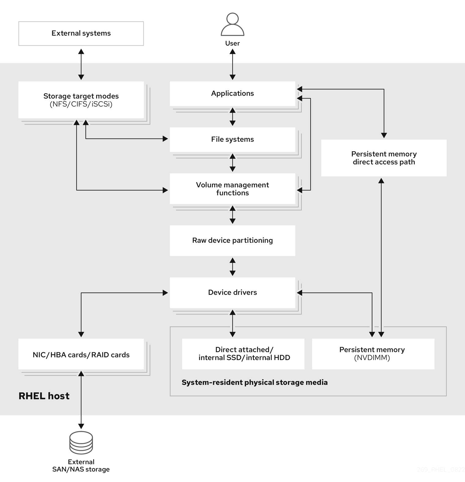
With remote storage, devices are accessed over LAN, the internet, or using a Fibre channel network. The following high level Red Hat Enterprise Linux storage diagram describes the different storage options.
Figure 1.1. High level Red Hat Enterprise Linux storage diagram
1.1. Local storage overview
Red Hat Enterprise Linux 8 offers several local storage options.
- Basic disk administration
Using
partedandfdisk, you can create, modify, delete, and view disk partitions. The following are the partitioning layout standards:- Master Boot Record (MBR)
- It is used with BIOS-based computers. You can create primary, extended, and logical partitions.
- GUID Partition Table (GPT)
- It uses Globally Unique identifier (GUID) and provides unique disk and partition GUID.
To encrypt the partition, you can use Linux Unified Key Setup-on-disk-format (LUKS). To encrypt the partition, select the option during the installation and the prompt displays to enter the passphrase. This passphrase unlocks the encryption key.
- Storage consumption options
- Non-Volatile Dual In-line Memory Modules (NVDIMM) Management
- It is a combination of memory and storage. You can enable and manage various types of storage on NVDIMM devices connected to your system.
- Block Storage Management
- Data is stored in the form of blocks where each block has a unique identifier.
- File Storage
- Data is stored at file level on the local system. These data can be accessed locally using XFS (default) or ext4, and over a network by using NFS and SMB.
- Logical volumes
- Logical Volume Manager (LVM)
It creates logical devices from physical devices. Logical volume (LV) is a combination of the physical volumes (PV) and volume groups (VG). Configuring LVM include:
- Creating PV from the hard drives.
- Creating VG from the PV.
- Creating LV from the VG assigning mount points to the LV.
- Virtual Data Optimizer (VDO)
It is used for data reduction by using deduplication, compression, and thin provisioning. Using LV below VDO helps in:
- Extending of VDO volume
- Spanning VDO volume over multiple devices
- Local file systems
- XFS
- The default RHEL file system.
- Ext4
- A legacy file system.
- Stratis
- It is available as a Technology Preview. Stratis is a hybrid user-and-kernel local storage management system that supports advanced storage features.
1.2. Remote storage overview
The following are the remote storage options available in RHEL 8:
- Storage connectivity options
- iSCSI
- RHEL 8 uses the targetcli tool to add, remove, view, and monitor iSCSI storage interconnects.
- Fibre Channel (FC)
RHEL 8 provides the following native Fibre Channel drivers:
-
lpfc -
qla2xxx -
Zfcp
-
- Non-volatile Memory Express (NVMe)
An interface which allows host software utility to communicate with solid state drives. Use the following types of fabric transport to configure NVMe over fabrics:
- NVMe over fabrics using Remote Direct Memory Access (RDMA).
- NVMe over fabrics using Fibre Channel (FC)
- Device Mapper multipathing (DM Multipath)
- Allows you to configure multiple I/O paths between server nodes and storage arrays into a single device. These I/O paths are physical SAN connections that can include separate cables, switches, and controllers.
- Network file system
- NFS
- SMB
1.3. GFS2 file system overview
The Red Hat Global File System 2 (GFS2) file system is a 64-bit symmetric cluster file system which provides a shared name space and manages coherency between multiple nodes sharing a common block device. A GFS2 file system is intended to provide a feature set which is as close as possible to a local file system, while at the same time enforcing full cluster coherency between nodes. To achieve this, the nodes employ a cluster-wide locking scheme for file system resources. This locking scheme uses communication protocols such as TCP/IP to exchange locking information.
In a few cases, the Linux file system API does not allow the clustered nature of GFS2 to be totally transparent; for example, programs using POSIX locks in GFS2 should avoid using the GETLK function since, in a clustered environment, the process ID may be for a different node in the cluster. In most cases however, the functionality of a GFS2 file system is identical to that of a local file system.
The Red Hat Enterprise Linux Resilient Storage Add-On provides GFS2, and it depends on the Red Hat Enterprise Linux High Availability Add-On to provide the cluster management required by GFS2.
The gfs2.ko kernel module implements the GFS2 file system and is loaded on GFS2 cluster nodes.
To get the best performance from GFS2, it is important to take into account the performance considerations which stem from the underlying design. Just like a local file system, GFS2 relies on the page cache in order to improve performance by local caching of frequently used data. In order to maintain coherency across the nodes in the cluster, cache control is provided by the glock state machine.
Additional resources
Chapter 2. Managing local storage using RHEL System Roles
To manage LVM and local file systems (FS) using Ansible, you can use the storage role, which is one of the RHEL System Roles available in RHEL 8.
Using the storage role enables you to automate administration of file systems on disks and logical volumes on multiple machines and across all versions of RHEL starting with RHEL 7.7.
For more information about RHEL System Roles and how to apply them, see Introduction to RHEL System Roles.
2.1. Introduction to the storage RHEL System Role
The storage role can manage:
- File systems on disks which have not been partitioned
- Complete LVM volume groups including their logical volumes and file systems
- MD RAID volumes and their file systems
With the storage role, you can perform the following tasks:
- Create a file system
- Remove a file system
- Mount a file system
- Unmount a file system
- Create LVM volume groups
- Remove LVM volume groups
- Create logical volumes
- Remove logical volumes
- Create RAID volumes
- Remove RAID volumes
- Create LVM volume groups with RAID
- Remove LVM volume groups with RAID
- Create encrypted LVM volume groups
- Create LVM logical volumes with RAID
2.2. Parameters that identify a storage device in the storage RHEL System Role
Your storage role configuration affects only the file systems, volumes, and pools that you list in the following variables.
storage_volumesList of file systems on all unpartitioned disks to be managed.
storage_volumescan also includeraidvolumes.Partitions are currently unsupported.
storage_poolsList of pools to be managed.
Currently the only supported pool type is LVM. With LVM, pools represent volume groups (VGs). Under each pool there is a list of volumes to be managed by the role. With LVM, each volume corresponds to a logical volume (LV) with a file system.
2.3. Example Ansible playbook to create an XFS file system on a block device
The example Ansible playbook applies the storage role to create an XFS file system on a block device using the default parameters.
The storage role can create a file system only on an unpartitioned, whole disk or a logical volume (LV). It cannot create the file system on a partition.
Example 2.1. A playbook that creates XFS on /dev/sdb
---
- hosts: all
  vars:
    storage_volumes:
      - name: barefs
        type: disk
        disks:
          - sdb
        fs_type: xfs
  roles:
- rhel-system-roles.storage-
The volume name (
barefsin the example) is currently arbitrary. Thestoragerole identifies the volume by the disk device listed under thedisks:attribute. -
You can omit the
fs_type: xfsline because XFS is the default file system in RHEL 8. To create the file system on an LV, provide the LVM setup under the
disks:attribute, including the enclosing volume group. For details, see Example Ansible playbook to manage logical volumes.Do not provide the path to the LV device.
Additional resources
-
The
/usr/share/ansible/roles/rhel-system-roles.storage/README.mdfile.
2.4. Example Ansible playbook to persistently mount a file system
The example Ansible applies the storage role to immediately and persistently mount an XFS file system.
Example 2.2. A playbook that mounts a file system on /dev/sdb to /mnt/data
---
- hosts: all
  vars:
    storage_volumes:
      - name: barefs
        type: disk
        disks:
          - sdb
        fs_type: xfs
        mount_point: /mnt/data
        mount_user: somebody
        mount_group: somegroup
        mount_mode: 0755
  roles:
- rhel-system-roles.storage-
This playbook adds the file system to the
/etc/fstabfile, and mounts the file system immediately. -
If the file system on the
/dev/sdbdevice or the mount point directory do not exist, the playbook creates them.
Additional resources
-
The
/usr/share/ansible/roles/rhel-system-roles.storage/README.mdfile.
2.5. Example Ansible playbook to manage logical volumes
The example Ansible playbook applies the storage role to create an LVM logical volume in a volume group.
Example 2.3. A playbook that creates a mylv logical volume in the myvg volume group
- hosts: all
  vars:
    storage_pools:
      - name: myvg
        disks:
          - sda
          - sdb
          - sdc
        volumes:
          - name: mylv
            size: 2G
            fs_type: ext4
            mount_point: /mnt/data
  roles:
    - rhel-system-roles.storage
The
myvgvolume group consists of the following disks:-
/dev/sda -
/dev/sdb -
/dev/sdc
-
-
If the
myvgvolume group already exists, the playbook adds the logical volume to the volume group. -
If the
myvgvolume group does not exist, the playbook creates it. -
The playbook creates an Ext4 file system on the
mylvlogical volume, and persistently mounts the file system at/mnt.
Additional resources
-
The
/usr/share/ansible/roles/rhel-system-roles.storage/README.mdfile.
2.6. Example Ansible playbook to enable online block discard
The example Ansible playbook applies the storage role to mount an XFS file system with online block discard enabled.
Example 2.4. A playbook that enables online block discard on /mnt/data/
---
- hosts: all
  vars:
    storage_volumes:
      - name: barefs
        type: disk
        disks:
          - sdb
        fs_type: xfs
        mount_point: /mnt/data
        mount_options: discard
  roles:
    - rhel-system-roles.storage
Additional resources
- Example Ansible playbook to persistently mount a file system
-
The
/usr/share/ansible/roles/rhel-system-roles.storage/README.mdfile.
2.7. Example Ansible playbook to create and mount an Ext4 file system
The example Ansible playbook applies the storage role to create and mount an Ext4 file system.
Example 2.5. A playbook that creates Ext4 on /dev/sdb and mounts it at /mnt/data
---
- hosts: all
  vars:
    storage_volumes:
      - name: barefs
        type: disk
        disks:
          - sdb
        fs_type: ext4
        fs_label: label-name
        mount_point: /mnt/data
  roles:
- rhel-system-roles.storage-
The playbook creates the file system on the
/dev/sdbdisk. -
The playbook persistently mounts the file system at the
/mnt/datadirectory. -
The label of the file system is
label-name.
Additional resources
-
The
/usr/share/ansible/roles/rhel-system-roles.storage/README.mdfile.
2.8. Example Ansible playbook to create and mount an ext3 file system
The example Ansible playbook applies the storage role to create and mount an Ext3 file system.
Example 2.6. A playbook that creates Ext3 on /dev/sdb and mounts it at /mnt/data
---
- hosts: all
  vars:
    storage_volumes:
      - name: barefs
        type: disk
        disks:
          - sdb
        fs_type: ext3
        fs_label: label-name
        mount_point: /mnt/data
        mount_user: somebody
        mount_group: somegroup
        mount_mode: 0755
  roles:
- rhel-system-roles.storage-
The playbook creates the file system on the
/dev/sdbdisk. -
The playbook persistently mounts the file system at the
/mnt/datadirectory. -
The label of the file system is
label-name.
Additional resources
-
The
/usr/share/ansible/roles/rhel-system-roles.storage/README.mdfile.
2.9. Example Ansible playbook to resize an existing file system on LVM using the storage RHEL System Role
The example Ansible playbook applies the storage RHEL System Role to resize an LVM logical volume with a file system.
Using the Resizing action in other file systems can destroy the data on the device you are working on.
Example 2.7. A playbook that resizes existing mylv1 and myvl2 logical volumes in the myvg volume group
---

- hosts: all
   vars:
    storage_pools:
      - name: myvg
        disks:
          - /dev/sda
          - /dev/sdb
          - /dev/sdc
        volumes:
            - name: mylv1
              size: 10 GiB
              fs_type: ext4
              mount_point: /opt/mount1
            - name: mylv2
              size: 50 GiB
              fs_type: ext4
              mount_point: /opt/mount2

- name: Create LVM pool over three disks
  include_role:
    name: rhel-system-roles.storage
This playbook resizes the following existing file systems:
-
The Ext4 file system on the
mylv1volume, which is mounted at/opt/mount1, resizes to 10 GiB. -
The Ext4 file system on the
mylv2volume, which is mounted at/opt/mount2, resizes to 50 GiB.
-
The Ext4 file system on the
Additional resources
-
The
/usr/share/ansible/roles/rhel-system-roles.storage/README.mdfile.
2.10. Example Ansible playbook to create a swap volume using the storage RHEL System Role
This section provides an example Ansible playbook. This playbook applies the storage role to create a swap volume, if it does not exist, or to modify the swap volume, if it already exist, on a block device using the default parameters.
Example 2.8. A playbook that creates or modify an existing XFS on /dev/sdb
---
- name: Create a disk device with swap
- hosts: all
  vars:
    storage_volumes:
      - name: swap_fs
        type: disk
        disks:
          - /dev/sdb
	size: 15 GiB
        fs_type: swap
  roles:
- rhel-system-roles.storage-
The volume name (
swap_fsin the example) is currently arbitrary. Thestoragerole identifies the volume by the disk device listed under thedisks:attribute.
Additional resources
-
The
/usr/share/ansible/roles/rhel-system-roles.storage/README.mdfile.
2.11. Configuring a RAID volume using the storage System Role
With the storage System Role, you can configure a RAID volume on RHEL using Red Hat Ansible Automation Platform and Ansible-Core. Create an Ansible playbook with the parameters to configure a RAID volume to suit your requirements.
Prerequisites
- The Ansible Core package is installed on the control machine.
-
You have the
rhel-system-rolespackage installed on the system from which you want to run the playbook. -
You have an inventory file detailing the systems on which you want to deploy a RAID volume using the
storageSystem Role.
Procedure
Create a new playbook.yml file with the following content:
--- - name: Configure the storage hosts: managed-node-01.example.com tasks: - name: Create a RAID on sdd, sde, sdf, and sdg include_role: name: rhel-system-roles.storage vars: storage_safe_mode: false storage_volumes: - name: data type: raid disks: [sdd, sde, sdf, sdg] raid_level: raid0 raid_chunk_size: 32 KiB mount_point: /mnt/data state: presentWarningDevice names might change in certain circumstances, for example, when you add a new disk to a system. Therefore, to prevent data loss, do not use specific disk names in the playbook.
Optional: Verify the playbook syntax:
# ansible-playbook --syntax-check playbook.ymlRun the playbook:
# ansible-playbook -i inventory.file /path/to/file/playbook.yml
Additional resources
- Managing RAID
-
The
/usr/share/ansible/roles/rhel-system-roles.storage/README.mdfile - Preparing a control node and managed nodes to use RHEL System Roles
2.12. Configuring an LVM pool with RAID using the storage RHEL System Role
With the storage System Role, you can configure an LVM pool with RAID on RHEL using Red Hat Ansible Automation Platform. You can set up an Ansible playbook with the available parameters to configure an LVM pool with RAID.
Prerequisites
- The Ansible Core package is installed on the control machine.
-
You have the
rhel-system-rolespackage installed on the system from which you want to run the playbook. -
You have an inventory file detailing the systems on which you want to configure an LVM pool with RAID using the
storageSystem Role.
Procedure
Create a new
playbook.ymlfile with the following content:- hosts: all vars: storage_safe_mode: false storage_pools: - name: my_pool type: lvm disks: [sdh, sdi] raid_level: raid1 volumes: - name: my_volume size: "1 GiB" mount_point: "/mnt/app/shared" fs_type: xfs state: present roles: - name: rhel-system-roles.storageNoteTo create an LVM pool with RAID, you must specify the RAID type using the
raid_levelparameter.Optional: Verify playbook syntax.
# ansible-playbook --syntax-check playbook.ymlRun the playbook on your inventory file:
# ansible-playbook -i inventory.file /path/to/file/playbook.yml
Additional resources
- Managing RAID.
-
The
/usr/share/ansible/roles/rhel-system-roles.storage/README.mdfile.
2.13. Configuring a stripe size for RAID LVM volumes using the storage RHEL System Role
With the storage System Role, you can configure a stripe size for RAID LVM volumes on RHEL using Red Hat Ansible Automation Platform. You can set up an Ansible playbook with the available parameters to configure an LVM pool with RAID.
Prerequisites
- The Ansible Core package is installed on the control machine.
- You have the rhel-system-roles package installed on the system from which you want to run the playbook.
- You have an inventory file detailing the systems on which you want to configure an LVM pool with RAID using the storage System Role.
Procedure
Create a new
playbook.ymlfile with the following content:hosts: all vars: storage_safe_mode: false storage_pools: - name: my_pool type: lvm disks: [sdh, sdi] volumes: - name: my_volume size: "1 GiB" mount_point: "/mnt/app/shared" fs_type: xfs raid_level: raid1 raid_stripe_size: "256 KiB" state: present roles: - name: rhel-system-roles.storageOptional: Verify playbook syntax:
# ansible-playbook --syntax-check playbook.ymlRun the playbook on your inventory file:
# ansible-playbook -i inventory.file /path/to/file/playbook.yml
Additional resources
- Managing RAID
-
The
/usr/share/ansible/roles/rhel-system-roles.storage/README.mdfile.
2.14. Example Ansible playbook to compress and deduplicate a VDO volume on LVM using the storage RHEL System Role
The example Ansible playbook applies the storage RHEL System Role to enable compression and deduplication of Logical Volumes (LVM) using Virtual Data Optimizer (VDO).
Example 2.9. A playbook that creates a mylv1 LVM VDO volume in the myvg volume group
---
- name: Create LVM VDO volume under volume group 'myvg'
  hosts: all
  roles:
    -rhel-system-roles.storage
  vars:
    storage_pools:
     - name: myvg
       disks:
         - /dev/sdb
       volumes:
         - name: mylv1
           compression: true
           deduplication: true
           vdo_pool_size: 10 GiB
           size: 30 GiB
           mount_point: /mnt/app/shared
In this example, the compression and deduplication pools are set to true, which specifies that the VDO is used. The following describes the usage of these parameters:
-
The
deduplicationis used to deduplicate the duplicated data stored on the storage volume. - The compression is used to compress the data stored on the storage volume, which results in more storage capacity.
-
The vdo_pool_size specifies the actual size the volume takes on the device. The virtual size of VDO volume is set by the
sizeparameter. NOTE: Because of the Storage role use of LVM VDO, only one volume per pool can use the compression and deduplication.
2.15. Creating a LUKS2 encrypted volume using the storage RHEL System Role
You can use the storage role to create and configure a volume encrypted with LUKS by running an Ansible playbook.
Prerequisites
-
Access and permissions to one or more managed nodes, which are systems you want to configure with the
crypto_policiesSystem Role. - An inventory file, which lists the managed nodes.
-
Access and permissions to a control node, which is a system from which Red Hat Ansible Core configures other systems. On the control node, the
ansible-coreandrhel-system-rolespackages are installed.
RHEL 8.0-8.5 provided access to a separate Ansible repository that contains Ansible Engine 2.9 for automation based on Ansible. Ansible Engine contains command-line utilities such as ansible, ansible-playbook, connectors such as docker and podman, and many plugins and modules. For information about how to obtain and install Ansible Engine, see the How to download and install Red Hat Ansible Engine Knowledgebase article.
RHEL 8.6 and 9.0 have introduced Ansible Core (provided as the ansible-core package), which contains the Ansible command-line utilities, commands, and a small set of built-in Ansible plugins. RHEL provides this package through the AppStream repository, and it has a limited scope of support. For more information, see the Scope of support for the Ansible Core package included in the RHEL 9 and RHEL 8.6 and later AppStream repositories Knowledgebase article.
Procedure
Create a new
playbook.ymlfile with the following content:- hosts: all vars: storage_volumes: - name: barefs type: disk disks: - sdb fs_type: xfs fs_label: label-name mount_point: /mnt/data encryption: true encryption_password: your-password roles: - rhel-system-roles.storageYou can also add the other encryption parameters such as
encryption_key,encryption_cipher,encryption_key_size, andencryption_luksversion in the playbook.yml file.Optional: Verify playbook syntax:
# ansible-playbook --syntax-check playbook.ymlRun the playbook on your inventory file:
# ansible-playbook -i inventory.file /path/to/file/playbook.yml
Verification
View the encryption status:
# cryptsetup status sdb

/dev/mapper/sdb is active and is in use.
type: LUKS2
cipher: aes-xts-plain64
keysize: 512 bits
key location: keyring
device: /dev/sdb
[...]
Verify the created LUKS encrypted volume:
# cryptsetup luksDump /dev/sdb

Version:       	2
Epoch:         	6
Metadata area: 	16384 [bytes]
Keyslots area: 	33521664 [bytes]
UUID:          	a4c6be82-7347-4a91-a8ad-9479b72c9426
Label:         	(no label)
Subsystem:     	(no subsystem)
Flags:       	allow-discards

Data segments:
  0: crypt
	offset: 33554432 [bytes]
	length: (whole device)
	cipher: aes-xts-plain64
	sector: 4096 [bytes]
[...]
View the
cryptsetupparameters in theplaybook.ymlfile, which thestoragerole supports:# cat ~/playbook.yml - hosts: all vars: storage_volumes: - name: foo type: disk disks: - nvme0n1 fs_type: xfs fs_label: label-name mount_point: /mnt/data encryption: true #encryption_password: passwdpasswd encryption_key: /home/passwd_key encryption_cipher: aes-xts-plain64 encryption_key_size: 512 encryption_luks_version: luks2 roles: - rhel-system-roles.storage
Additional resources
- Encrypting block devices using LUKS
-
/usr/share/ansible/roles/rhel-system-roles.storage/README.mdfile
2.16. Example Ansible playbook to express pool volume sizes as percentage using the storage RHEL System Role
The example Ansible playbook applies the storage System Role to enable you to express Logical Manager Volumes (LVM) volume sizes as a percentage of the pool’s total size.
Example 2.10. A playbook that express volume sizes as a percentage of the pool’s total size
---
- name: Express volume sizes as a percentage of the pool's total size
  hosts: all
  roles
    - rhel-system-roles.storage
  vars:
    storage_pools:
    - name: myvg
      disks:
        - /dev/sdb
      volumes:
        - name: data
          size: 60%
          mount_point: /opt/mount/data
        - name: web
          size: 30%
          mount_point: /opt/mount/web
        - name: cache
          size: 10%
          mount_point: /opt/cache/mount
This example specifies the size of LVM volumes as a percentage of the pool size, for example: "60%". Additionally, you can also specify the size of LVM volumes as a percentage of the pool size in a human-readable size of the file system, for example, "10g" or "50 GiB".
2.17. Additional resources
-
/usr/share/doc/rhel-system-roles/storage/ -
/usr/share/ansible/roles/rhel-system-roles.storage/
Chapter 3. Disk partitions
To divide a disk into one or more logical areas, use the disk partitioning utility. It enables separate management of each partition.
3.1. Overview of partitions
The hard disk stores information about the location and size of each disk partition in the partition table. Using information from the partition table, the operating system treats each partition as a logical disk. Some of the advantages of disk partitioning include:
- Reduce the likelihood of administrative oversights of Physical Volumes
- Ensure sufficient backup
- Provide efficient disk management
3.2. Considerations before modifying partitions on a disk
Before creating, removing, or resizing any disk partitions, consider the following aspects.
On a device, the type of the partition table determines the maximum number and size of individual partitions.
Maximum number of partitions:
On a device formatted with the Master Boot Record (MBR) partition table, you can have:
- Up to four primary partitions.
Up to three primary partitions, one extended partition
- Multiple logical partitions within the extended partition
On a device formatted with the GUID Partition Table (GPT), you can have:
Up to 128 partitions, if using the
partedutility.- Though the GPT specification allows more partitions by increasing the reserved size of the partition table, the parted utility limits the area required for 128 partitions.
Maximum size of partitions:
On a device formatted with the Master Boot Record (MBR) partition table:
- While using 512b sector drives, the maximum size is 2 TiB.
- While using 4k sector drives, the maximum size is 16 TiB.
On a device formatted with the GUID Partition Table (GPT):
- While using 512b sector drives, the maximum size is 8 ZiB.
- While using 4k sector drives, the maximum size is 64 ZiB.
By using the parted utility, you can specify the partition size using multiple different suffixes:
MiB, GiB, or TiB
- Size expressed in powers of 2.
- The starting point of the partition is aligned to the exact sector specified by size.
- The ending point is aligned to the specified size minus 1 sector.
MB, GB, or TB:
- Size expressed in powers of 10.
- The starting and ending points are aligned within one half of the specified unit. For example, ±500KB when using the MB suffix.
This section does not cover the DASD partition table, which is specific to the IBM Z architecture.
Additional resources
3.3. Comparison of partition table types
To enable partitions on a device, format a block device with different types of partition tables. The following table compares the properties of different types of partition tables that you can create on a block device.
Table 3.1. Partition table types
| Partition table | Maximum number of partitions | Maximum partition size |
|---|---|---|
| Master Boot Record (MBR) | 4 primary, or 3 primary and 1 extended partition with 12 logical partitions | 2TiB |
| GUID Partition Table (GPT) | 128 | 8ZiB |
3.4. MBR disk partitions
The partition table is stored at the very start of the disk, before any file system or user data. For a more clear example, the partition table is shown as being separate in the following diagrams.
Figure 3.1. Disk with MBR partition table
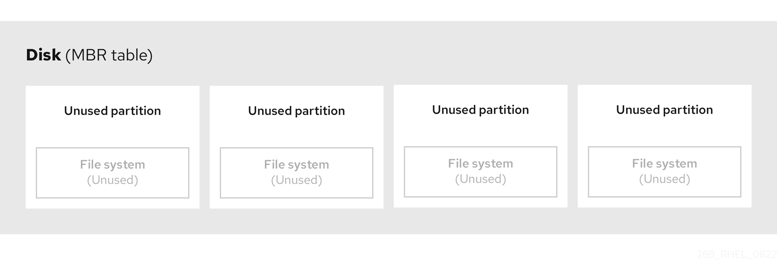
As the previous diagram shows, the partition table is divided into four sections of four unused primary partitions. A primary partition is a partition on a hard disk drive that contains only one logical drive (or section). Each logical drive holds the information necessary to define a single partition, meaning that the partition table can define no more than four primary partitions.
Each partition table entry contains important characteristics of the partition:
- The points on the disk where the partition starts and ends
-
The state of the partition, as only one partition can be flagged as
active - The type of partition
The starting and ending points define the size and location of the partition on the disk. Some of the operating systems boot loaders use the active flag. That means that the operating system in the partition that is marked "active" is booted.
The type is a number that identifies the anticipated usage of a partition. Some operating systems use the partition type to:
- Denote a specific file system type
- Flag the partition as being associated with a particular operating system
- Indicate that the partition contains a bootable operating system
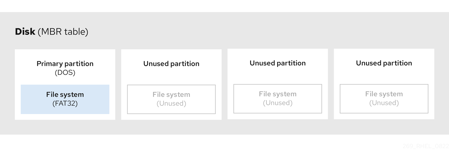
The following diagram shows an example of a drive with a single partition. In this example, the first partition is labeled as DOS partition type:
Figure 3.2. Disk with a single partition
Additional resources
3.5. Extended MBR partitions
To create additional partitions, if needed, set the type to extended.
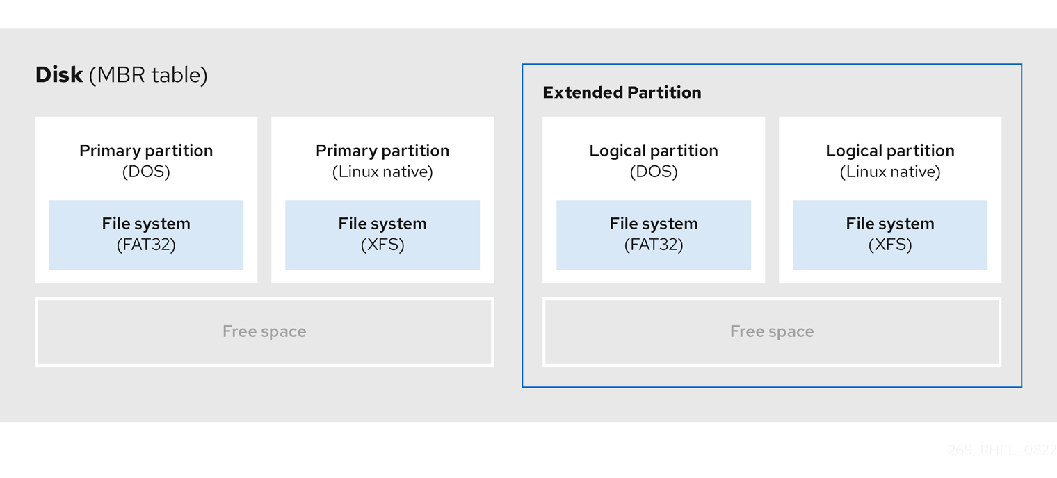
An extended partition is similar to a disk drive. It has its own partition table, which points to one or more logical partitions, contained entirely within the extended partition. The following diagram shows a disk drive with two primary partitions, and one extended partition containing two logical partitions, along with some unpartitioned free space.
Figure 3.3. Disk with both two primary and an extended MBR partitions
You can have only up to four primary and extended partitions, but there is no fixed limit to the number of logical partitions. As a limit in Linux to access partitions, a single disk drive allows maximum 15 logical partitions.
3.6. MBR partition types
The table below shows a list of some of the most commonly used MBR partition types and hexadecimal numbers to represent them.
Table 3.2. MBR partition types
| MBR partition type | Value | MBR partition type | Value |
| Empty | 00 | Novell Netware 386 | 65 |
| DOS 12-bit FAT | 01 | PIC/IX | 75 |
| XENIX root | O2 | Old MINIX | 80 |
| XENIX usr | O3 | Linux/MINUX | 81 |
| DOS 16-bit ⇐32M | 04 | Linux swap | 82 |
| Extended | 05 | Linux native | 83 |
| DOS 16-bit >=32 | 06 | Linux extended | 85 |
| OS/2 HPFS | 07 | Amoeba | 93 |
| AIX | 08 | Amoeba BBT | 94 |
| AIX bootable | 09 | BSD/386 | a5 |
| OS/2 Boot Manager | 0a | OpenBSD | a6 |
| Win95 FAT32 | 0b | NEXTSTEP | a7 |
| Win95 FAT32 (LBA) | 0c | BSDI fs | b7 |
| Win95 FAT16 (LBA) | 0e | BSDI swap | b8 |
| Win95 Extended (LBA) | 0f | Syrinx | c7 |
| Venix 80286 | 40 | CP/M | db |
| Novell | 51 | DOS access | e1 |
| PRep Boot | 41 | DOS R/O | e3 |
| GNU HURD | 63 | DOS secondary | f2 |
| Novell Netware 286 | 64 | BBT | ff |
3.7. GUID partition table
The GUID partition table (GPT) is a partitioning scheme based on the Globally Unique Identifier (GUID).
GPT deals with the limitations of the Mater Boot Record (MBR) partition table. The MBR partition table cannot address storage larger than 2 TiB, equal to approximately 2.2 TB. Instead, GPT supports hard disks with larger capacity. The maximum addressable disk size is 8 ZiB, when using 512b sector drives, and 64 ZiB, when using 4096b sector drives. In addition, by default, GPT supports creation of up to 128 primary partitions. Extend the maximum amount of primary partitions by allocating more space to the partition table.
A GPT has partition types based on GUIDs. Certain partitions require a specific GUID. For example, the system partition for Extensible Firmware Interface (EFI) boot loaders require GUID C12A7328-F81F-11D2-BA4B-00A0C93EC93B.
GPT disks use logical block addressing (LBA) and a partition layout as follows:
- For backward compatibility with MBR disks, the system reserves the first sector (LBA 0) of GPT for MBR data, and applies the name "protective MBR".
Primary GPT
- The header begins on the second logical block (LBA 1) of the device. The header contains the disk GUID, the location of the primary partition table, the location of the secondary GPT header, and CRC32 checksums of itself, and the primary partition table. It also specifies the number of partition entries on the table.
- By default, the primary GPT includes 128 partition entries. Each partition has an entry size of 128 bytes, a partition type GUID and a unique partition GUID.
Secondary GPT
- For recovery, it is useful as a backup table in case the primary partition table is corrupted.
- The last logical sector of the disk contains the secondary GPT header and recovers GPT information, in case the primary header is corrupted.
It contains:
- The disk GUID
- The location of the secondary partition table and the primary GPT header
- CRC32 checksums of itself
- The secondary partition table
- The number of possible partition entries
Figure 3.4. Disk with a GUID Partition Table

For a successful installation of the boot loader onto a GPT disk a BIOS boot partition must be present. Reuse is possible only if the disk already contains a BIOS boot partition. This includes disks initialized by the Anaconda installation program.
3.8. Partition types
There are multiple ways to manage partition types:
-
The
fdiskutility supports the full range of partition types by specifying hexadecimal codes. -
The
systemd-gpt-auto-generator, a unit generator utility, uses the partition type to automatically identify and mount devices. The
partedutility maps out the partition type with flags. Thepartedutility handles only certain partition types, for example LVM, swap or RAID.The
partedutility supports setting the following flags:-
boot -
root -
swap -
hidden -
raid -
lvm -
lba -
legacy_boot -
irst -
esp -
palo
-
The parted utility optionally accepts a file system type argument while creating a partition. See Creating a partition with parted
for a list of the required conditions. Use the value to:
- Set the partition flags on MBR.
-
Set the partition UUID type on GPT. For example, the
swap,fat, orhfsfile system types set different GUIDs. The default value is the Linux Data GUID.
The argument does not modify the file system on the partition. It only differentiates between the supported flags and GUIDs.
The following file system types are supported:
-
xfs -
ext2 -
ext3 -
ext4 -
fat16 -
fat32 -
hfs -
hfs+ -
linux-swap -
ntfs -
reiserfs
The only supported local file systems in RHEL 8 are ext4 and xfs.
3.9. Partition naming scheme
Red Hat Enterprise Linux uses a file-based naming scheme, with file names in the form of /dev/xxyN.
Device and partition names consist of the following structure:
/dev/-
Name of the directory that contains all device files. Hard disks contain partitions, thus the files representing all possible partitions are located in
/dev. xx- The first two letters of the partition name indicate the type of device that contains the partition.
y-
This letter indicates the specific device containing the partition. For example,
/dev/sdafor the first hard disk and/dev/sdbfor the second. You can use more letters in systems with more than 26 drives, for example,/dev/sdaa1. N-
The final letter indicates the number to represent the partition. The first four (primary or extended) partitions are numbered
1through4. Logical partitions start at5. For example,/dev/sda3is the third primary or extended partition on the first hard disk, and/dev/sdb6is the second logical partition on the second hard disk. Drive partition numbering applies only to MBR partition tables. Note that N does not always mean partition.
Even if Red Hat Enterprise Linux can identify and refer to all types of disk partitions, it might not be able to read the file system and therefore access stored data on every partition type. However, in many cases, it is possible to successfully access data on a partition dedicated to another operating system.
3.10. Mount points and disk partitions
In Red Hat Enterprise Linux, each partition forms a part of the storage, necessary to support a single set of files and directories. Mounting a partition makes the storage of that partition available, starting at the specified directory known as a mount point.
For example, if partition /dev/sda5 is mounted on /usr/, it means that all files and directories under /usr/ physically reside on /dev/sda5. The file /usr/share/doc/FAQ/txt/Linux-FAQ resides on /dev/sda5, while the file /etc/gdm/custom.conf does not.
Continuing the example, it is also possible that one or more directories below /usr/ would be mount points for other partitions. For example, /usr/local/man/whatis resides on /dev/sda7, rather than on /dev/sda5, if /usr/local includes a mounted /dev/sda7 partition.
Chapter 4. Getting started with partitions
Use disk partitioning to divide a disk into one or more logical areas which enables work on each partition separately. The hard disk stores information about the location and size of each disk partition in the partition table. Using the table, each partition then appears as a logical disk to the operating system. You can then read and write on those individual disks.
For an overview of the advantages and disadvantages to using partitions on block devices, see What are the advantages and disadvantages to using partitioning on LUNs, either directly or with LVM in between?.
4.1. Creating a partition table on a disk with parted
Use the parted utility to format a block device with a partition table more easily.
Formatting a block device with a partition table deletes all data stored on the device.
Procedure
Start the interactive
partedshell:# parted block-deviceDetermine if there already is a partition table on the device:
# (parted) print
If the device already contains partitions, they will be deleted in the following steps.
Create the new partition table:
# (parted) mklabel table-typeReplace table-type with with the intended partition table type:
-
msdosfor MBR -
gptfor GPT
-
Example 4.1. Creating a GUID Partition Table (GPT) table
To create a GPT table on the disk, use:
# (parted) mklabel gpt
The changes start applying after you enter this command.
View the partition table to confirm that it is created:
# (parted) print
Exit the
partedshell:# (parted) quit
Additional resources
-
parted(8)man page.
4.2. Viewing the partition table with parted
Display the partition table of a block device to see the partition layout and details about individual partitions. You can view the partition table on a block device using the parted utility.
Procedure
Start the
partedutility. For example, the following output lists the device/dev/sda:# parted /dev/sda
View the partition table:
# (parted) print

Model: ATA SAMSUNG MZNLN256 (scsi)
Disk /dev/sda: 256GB
Sector size (logical/physical): 512B/512B
Partition Table: msdos
Disk Flags:

Number  Start   End     Size    Type      File system  Flags
 1      1049kB  269MB   268MB   primary   xfs          boot
 2      269MB   34.6GB  34.4GB  primary
 3      34.6GB  45.4GB  10.7GB  primary
 4      45.4GB  256GB   211GB   extended
 5      45.4GB  256GB   211GB   logical
Optional: Switch to the device you want to examine next:
# (parted) select block-device
For a detailed description of the print command output, see the following:
Model: ATA SAMSUNG MZNLN256 (scsi)- The disk type, manufacturer, model number, and interface.
Disk /dev/sda: 256GB- The file path to the block device and the storage capacity.
Partition Table: msdos- The disk label type.
Number-
The partition number. For example, the partition with minor number 1 corresponds to
/dev/sda1. StartandEnd- The location on the device where the partition starts and ends.
Type- Valid types are metadata, free, primary, extended, or logical.
File system-
The file system type. If the
File systemfield of a device shows no value, this means that its file system type is unknown. Thepartedutility cannot recognize the file system on encrypted devices. Flags-
Lists the flags set for the partition. Available flags are
boot,root,swap,hidden,raid,lvm, orlba.
Additional resources
-
parted(8)man page.
4.3. Creating a partition with parted
As a system administrator, you can create new partitions on a disk by using the parted utility.
The required partitions are swap, /boot/, and / (root).
Prerequisites
- A partition table on the disk.
- If the partition you want to create is larger than 2TiB, format the disk with the GUID Partition Table (GPT).
Procedure
Start the
partedutility:# parted block-deviceView the current partition table to determine if there is enough free space:
# (parted) print
- Resize the partition in case there is not enough free space.
From the partition table, determine:
- The start and end points of the new partition.
- On MBR, what partition type it should be.
Create the new partition:
# (parted) mkpart part-type name fs-type start end
-
Replace part-type with with
primary,logical, orextended. This applies only to the MBR partition table. - Replace name with an arbitrary partition name. This is required for GPT partition tables.
-
Replace fs-type with
xfs,ext2,ext3,ext4,fat16,fat32,hfs,hfs+,linux-swap,ntfs, orreiserfs. The fs-type parameter is optional. Note that thepartedutility does not create the file system on the partition. -
Replace start and end with the sizes that determine the starting and ending points of the partition, counting from the beginning of the disk. You can use size suffixes, such as
512MiB,20GiB, or1.5TiB. The default size is in megabytes.
Example 4.2. Creating a small primary partition
To create a primary partition from 1024MiB until 2048MiB on an MBR table, use:
# (parted) mkpart primary 1024MiB 2048MiB
The changes start applying after you enter the command.
-
Replace part-type with with
View the partition table to confirm that the created partition is in the partition table with the correct partition type, file system type, and size:
# (parted) print
Exit the
partedshell:# (parted) quit
Register the new device node:
# udevadm settle
Verify that the kernel recognizes the new partition:
# cat /proc/partitions
Additional resources
-
parted(8)man page. - Creating a partition table on a disk with parted.
- Resizing a partition with parted
4.4. Setting a partition type with fdisk
You can set a partition type or flag, using the fdisk utility.
Prerequisites
- A partition on the disk.
Procedure
Start the interactive
fdiskshell:# fdisk block-deviceView the current partition table to determine the minor partition number:
Command (m for help): printYou can see the current partition type in the
Typecolumn and its corresponding type ID in theIdcolumn.Enter the partition type command and select a partition using its minor number:
Command (m for help): type
Partition number (1,2,3 default 3): 2
Optional: View the list in hexadecimal codes:
Hex code (type L to list all codes): LSet the partition type:
Hex code (type L to list all codes): 8eWrite your changes and exit the
fdiskshell:Command (m for help): write The partition table has been altered. Syncing disks.Verify your changes:
# fdisk --list block-device
4.5. Resizing a partition with parted
Using the parted utility, extend a partition to use unused disk space, or shrink a partition to use its capacity for different purposes.
Prerequisites
- Back up the data before shrinking a partition.
- If the partition you want to create is larger than 2TiB, format the disk with the GUID Partition Table (GPT).
- If you want to shrink the partition, first shrink the file system so that it is not larger than the resized partition.
XFS does not support shrinking.
Procedure
Start the
partedutility:# parted block-deviceView the current partition table:
# (parted) print
From the partition table, determine:
- The minor number of the partition.
- The location of the existing partition and its new ending point after resizing.
Resize the partition:
# (parted) resizepart 1 2GiB
- Replace 1 with the minor number of the partition that you are resizing.
-
Replace 2 with the size that determines the new ending point of the resized partition, counting from the beginning of the disk. You can use size suffixes, such as
512MiB,20GiB, or1.5TiB. The default size is in megabytes.
View the partition table to confirm that the resized partition is in the partition table with the correct size:
# (parted) print
Exit the
partedshell:# (parted) quit
Verify that the kernel registers the new partition:
# cat /proc/partitions
- Optional: If you extended the partition, extend the file system on it as well.
Additional resources
4.6. Removing a partition with parted
Using the parted utility, you can remove a disk partition to free up disk space.
Removing a partition deletes all data stored on the partition.
Procedure
Start the interactive
partedshell:# parted block-device-
Replace block-device with the path to the device where you want to remove a partition: for example,
/dev/sda.
-
Replace block-device with the path to the device where you want to remove a partition: for example,
View the current partition table to determine the minor number of the partition to remove:
(parted) print
Remove the partition:
(parted) rm minor-number- Replace minor-number with the minor number of the partition you want to remove.
The changes start applying as soon as you enter this command.
Verify that you have removed the partition from the partition table:
(parted) print
Exit the
partedshell:(parted) quit
Verify that the kernel registers that the partition is removed:
# cat /proc/partitions
-
Remove the partition from the
/etc/fstabfile, if it is present. Find the line that declares the removed partition, and remove it from the file. Regenerate mount units so that your system registers the new
/etc/fstabconfiguration:# systemctl daemon-reload
If you have deleted a swap partition or removed pieces of LVM, remove all references to the partition from the kernel command line:
List active kernel options and see if any option references the removed partition:
# grubby --info=ALL
Remove the kernel options that reference the removed partition:
# grubby --update-kernel=ALL --remove-args="option"
To register the changes in the early boot system, rebuild the
initramfsfile system:# dracut --force --verbose
Additional resources
-
parted(8)man page
Chapter 5. Strategies for repartitioning a disk
There are different approaches to repartitioning a disk. These include:
- Unpartitioned free space is available.
- An unused partition is available.
- Free space in an actively used partition is available.
The following examples are simplified for clarity and do not reflect the exact partition layout when actually installing Red Hat Enterprise Linux.
5.1. Using unpartitioned free space
Partitions that are already defined and do not span the entire hard disk, leave unallocated space that is not part of any defined partition. The following diagram shows what this might look like.
Figure 5.1. Disk with unpartitioned free space
The first diagram represents a disk with one primary partition and an undefined partition with unallocated space. The second diagram represents a disk with two defined partitions with allocated space.
An unused hard disk also falls into this category. The only difference is that all the space is not part of any defined partition.
On a new disk, you can create the necessary partitions from the unused space. Most preinstalled operating systems are configured to take up all available space on a disk drive.
5.2. Using space from an unused partition
In the following example, the first diagram represents a disk with an unused partition. The second diagram represents reallocating an unused partition for Linux.
Figure 5.2. Disk with an unused partition

To use the space allocated to the unused partition, delete the partition and then create the appropriate Linux partition instead. Alternatively, during the installation process, delete the unused partition and manually create new partitions.
5.3. Using free space from an active partition
This process can be difficult to manage because an active partition, that is already in use, contains the required free space. In most cases, hard disks of computers with preinstalled software contain one larger partition holding the operating system and data.
If you want to use an operating system (OS) on an active partition, you must reinstall the OS. Be aware that some computers, which include pre-installed software, do not include installation media to reinstall the original OS. Check whether this applies to your OS before you destroy an original partition and the OS installation.
To optimise the use of available free space, you can use the methods of destructive or non-destructive repartitioning.
5.3.1. Destructive repartitioning
Destructive repartitioning destroys the partition on your hard drive and creates several smaller partitions instead. Backup any needed data from the original partition as this method deletes the complete contents.
After creating a smaller partition for your existing operating system, you can:
- Reinstall software.
- Restore your data.
- Start your Red Hat Enterprise Linux installation.
The following diagram is a simplified representation of using the destructive repartitioning method.
Figure 5.3. Destructive repartitioning action on disk
This method deletes all data previously stored in the original partition.
5.3.2. Non-destructive repartitioning
Non-destructive repartitioning resizes partitions, without any data loss. This method is reliable, however it takes longer processing time on large drives.
The following is a list of methods, which can help initiate non-destructive repartitioning.
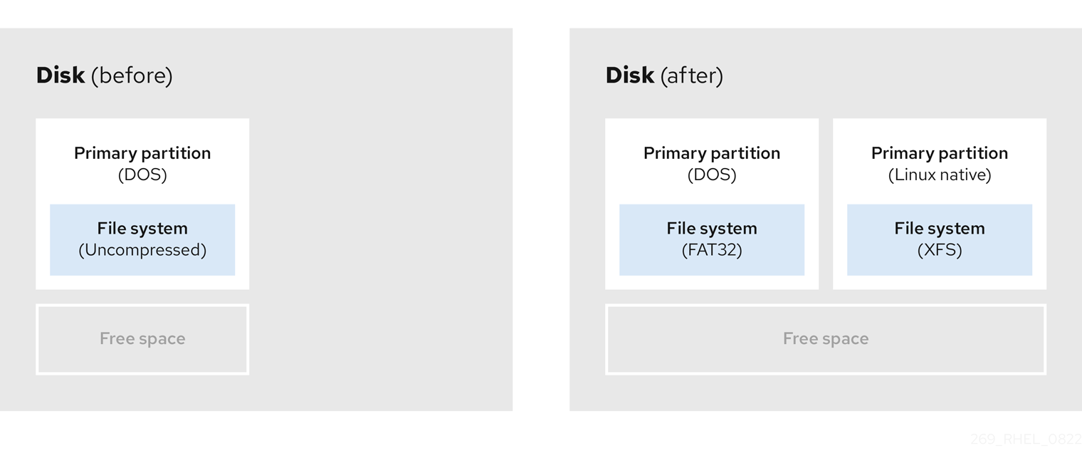
- Compress existing data
The storage location of some data cannot be changed. This can prevent the resizing of a partition to the required size, and ultimately lead to a destructive repartition process. Compressing data in an already existing partition can help you resize your partitions as needed. It can also help to maximize the free space available.
The following diagram is a simplified representation of this process.
Figure 5.4. Data compression on a disk
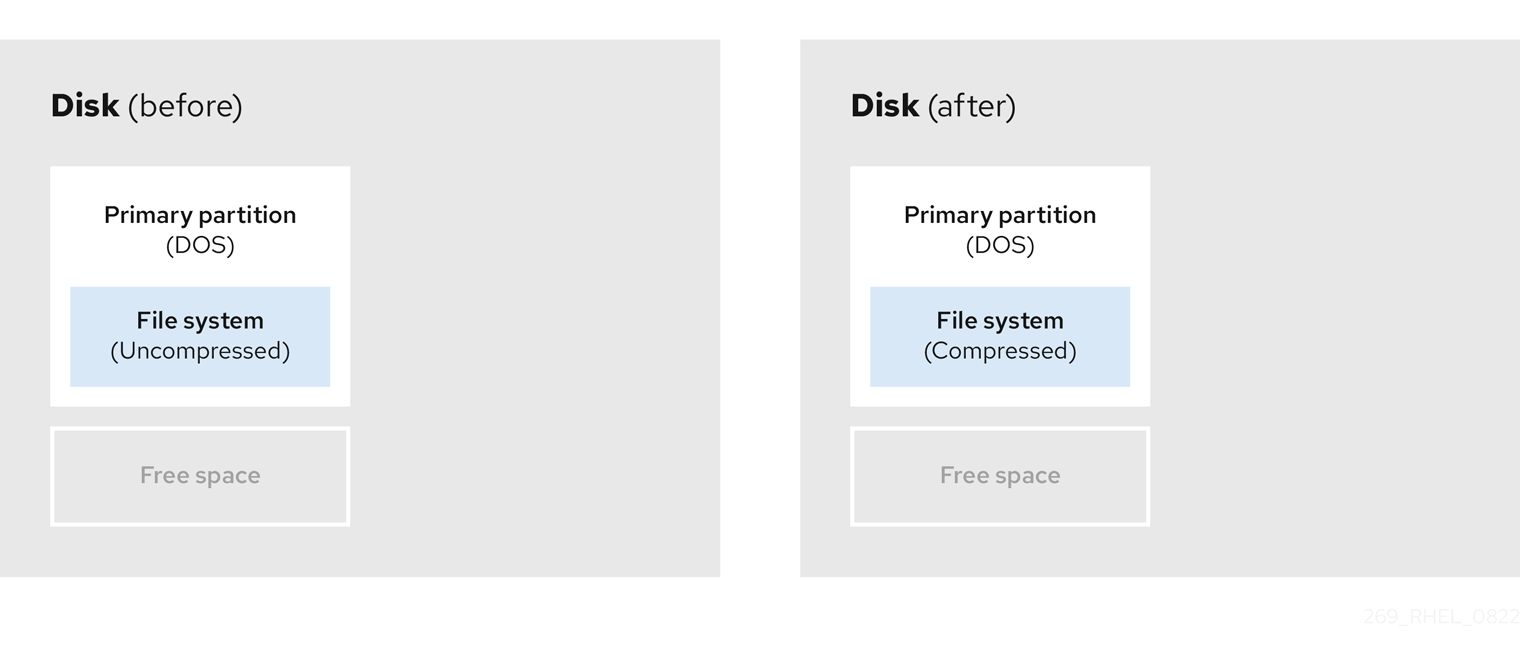
To avoid any possible data loss, create a backup before continuing with the compression process.
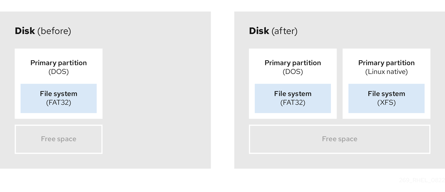
- Resize the existing partition
By resizing an already existing partition, you can free up more space. Depending on your resizing software, the results may vary. In the majority of cases, you can create a new unformatted partition of the same type, as the original partition.
The steps you take after resizing can depend on the software you use. In the following example, the best practice is to delete the new DOS (Disk Operating System) partition, and create a Linux partition instead. Verify what is most suitable for your disk before initiating the resizing process.
Figure 5.5. Partition resizing on a disk

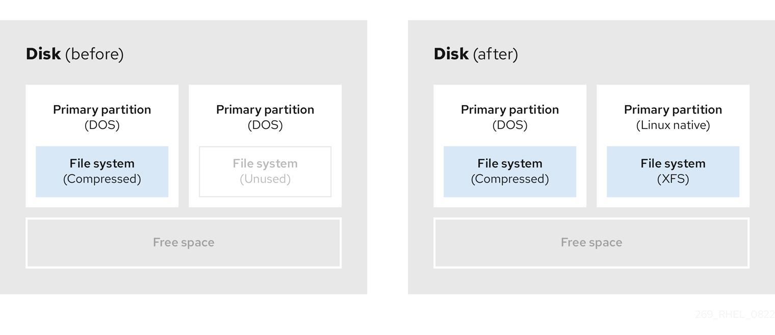
- Optional: Create new partitions
Some pieces of resizing software support Linux based systems. In such cases, there is no need to delete the newly created partition after resizing. Creating a new partition afterwards depends on the software you use.
The following diagram represents the disk state, before and after creating a new partition.
Figure 5.6. Disk with final partition configuration
Chapter 6. Overview of persistent naming attributes
As a system administrator, you need to refer to storage volumes using persistent naming attributes to build storage setups that are reliable over multiple system boots.
6.1. Disadvantages of non-persistent naming attributes
Red Hat Enterprise Linux provides a number of ways to identify storage devices. It is important to use the correct option to identify each device when used in order to avoid inadvertently accessing the wrong device, particularly when installing to or reformatting drives.
Traditionally, non-persistent names in the form of /dev/sd(major number)(minor number) are used on Linux to refer to storage devices. The major and minor number range and associated sd names are allocated for each device when it is detected. This means that the association between the major and minor number range and associated sd names can change if the order of device detection changes.
Such a change in the ordering might occur in the following situations:
- The parallelization of the system boot process detects storage devices in a different order with each system boot.
-
A disk fails to power up or respond to the SCSI controller. This results in it not being detected by the normal device probe. The disk is not accessible to the system and subsequent devices will have their major and minor number range, including the associated
sdnames shifted down. For example, if a disk normally referred to assdbis not detected, a disk that is normally referred to assdcwould instead appear assdb. -
A SCSI controller (host bus adapter, or HBA) fails to initialize, causing all disks connected to that HBA to not be detected. Any disks connected to subsequently probed HBAs are assigned different major and minor number ranges, and different associated
sdnames. - The order of driver initialization changes if different types of HBAs are present in the system. This causes the disks connected to those HBAs to be detected in a different order. This might also occur if HBAs are moved to different PCI slots on the system.
-
Disks connected to the system with Fibre Channel, iSCSI, or FCoE adapters might be inaccessible at the time the storage devices are probed, due to a storage array or intervening switch being powered off, for example. This might occur when a system reboots after a power failure, if the storage array takes longer to come online than the system take to boot. Although some Fibre Channel drivers support a mechanism to specify a persistent SCSI target ID to WWPN mapping, this does not cause the major and minor number ranges, and the associated
sdnames to be reserved; it only provides consistent SCSI target ID numbers.
These reasons make it undesirable to use the major and minor number range or the associated sd names when referring to devices, such as in the /etc/fstab file. There is the possibility that the wrong device will be mounted and data corruption might result.
Occasionally, however, it is still necessary to refer to the sd names even when another mechanism is used, such as when errors are reported by a device. This is because the Linux kernel uses sd names (and also SCSI host/channel/target/LUN tuples) in kernel messages regarding the device.
6.2. File system and device identifiers
This sections explains the difference between persistent attributes identifying file systems and block devices.
File system identifiers
File system identifiers are tied to a particular file system created on a block device. The identifier is also stored as part of the file system. If you copy the file system to a different device, it still carries the same file system identifier. On the other hand, if you rewrite the device, such as by formatting it with the mkfs utility, the device loses the attribute.
File system identifiers include:
- Unique identifier (UUID)
- Label
Device identifiers
Device identifiers are tied to a block device: for example, a disk or a partition. If you rewrite the device, such as by formatting it with the mkfs utility, the device keeps the attribute, because it is not stored in the file system.
Device identifiers include:
- World Wide Identifier (WWID)
- Partition UUID
- Serial number
Recommendations
- Some file systems, such as logical volumes, span multiple devices. Red Hat recommends accessing these file systems using file system identifiers rather than device identifiers.
6.3. Device names managed by the udev mechanism in /dev/disk/
The udev mechanism is used for all types of devices in Linux, and is not limited only for storage devices. It provides different kinds of persistent naming attributes in the /dev/disk/ directory. In the case of storage devices, Red Hat Enterprise Linux contains udev rules that create symbolic links in the /dev/disk/ directory. This enables you to refer to storage devices by:
- Their content
- A unique identifier
- Their serial number.
Although udev naming attributes are persistent, in that they do not change on their own across system reboots, some are also configurable.
6.3.1. File system identifiers
The UUID attribute in /dev/disk/by-uuid/
Entries in this directory provide a symbolic name that refers to the storage device by a unique identifier (UUID) in the content (that is, the data) stored on the device. For example:
/dev/disk/by-uuid/3e6be9de-8139-11d1-9106-a43f08d823a6
You can use the UUID to refer to the device in the /etc/fstab file using the following syntax:
UUID=3e6be9de-8139-11d1-9106-a43f08d823a6You can configure the UUID attribute when creating a file system, and you can also change it later on.
The Label attribute in /dev/disk/by-label/
Entries in this directory provide a symbolic name that refers to the storage device by a label in the content (that is, the data) stored on the device.
For example:
/dev/disk/by-label/Boot
You can use the label to refer to the device in the /etc/fstab file using the following syntax:
LABEL=BootYou can configure the Label attribute when creating a file system, and you can also change it later on.
6.3.2. Device identifiers
The WWID attribute in /dev/disk/by-id/
The World Wide Identifier (WWID) is a persistent, system-independent identifier that the SCSI Standard requires from all SCSI devices. The WWID identifier is guaranteed to be unique for every storage device, and independent of the path that is used to access the device. The identifier is a property of the device but is not stored in the content (that is, the data) on the devices.
This identifier can be obtained by issuing a SCSI Inquiry to retrieve the Device Identification Vital Product Data (page 0x83) or Unit Serial Number (page 0x80).
Red Hat Enterprise Linux automatically maintains the proper mapping from the WWID-based device name to a current /dev/sd name on that system. Applications can use the /dev/disk/by-id/ name to reference the data on the disk, even if the path to the device changes, and even when accessing the device from different systems.
Example 6.1. WWID mappings
| WWID symlink | Non-persistent device | Note |
|---|---|---|
|
|
|
A device with a page |
|
|
|
A device with a page |
|
|
| A disk partition |
In addition to these persistent names provided by the system, you can also use udev rules to implement persistent names of your own, mapped to the WWID of the storage.
The Partition UUID attribute in /dev/disk/by-partuuid
The Partition UUID (PARTUUID) attribute identifies partitions as defined by GPT partition table.
Example 6.2. Partition UUID mappings
| PARTUUID symlink | Non-persistent device |
|---|---|
|
|
|
|
|
|
|
|
|
The Path attribute in /dev/disk/by-path/
This attribute provides a symbolic name that refers to the storage device by the hardware path used to access the device.
The Path attribute fails if any part of the hardware path (for example, the PCI ID, target port, or LUN number) changes. The Path attribute is therefore unreliable. However, the Path attribute may be useful in one of the following scenarios:
- You need to identify a disk that you are planning to replace later.
- You plan to install a storage service on a disk in a specific location.
6.4. The World Wide Identifier with DM Multipath
You can configure Device Mapper (DM) Multipath to map between the World Wide Identifier (WWID) and non-persistent device names.
If there are multiple paths from a system to a device, DM Multipath uses the WWID to detect this. DM Multipath then presents a single "pseudo-device" in the /dev/mapper/wwid directory, such as /dev/mapper/3600508b400105df70000e00000ac0000.
The command multipath -l shows the mapping to the non-persistent identifiers:
-
Host:Channel:Target:LUN -
/dev/sdname -
major:minornumber
Example 6.3. WWID mappings in a multipath configuration
An example output of the multipath -l command:
3600508b400105df70000e00000ac0000 dm-2 vendor,product
[size=20G][features=1 queue_if_no_path][hwhandler=0][rw]
\_ round-robin 0 [prio=0][active]
 \_ 5:0:1:1 sdc 8:32  [active][undef]
 \_ 6:0:1:1 sdg 8:96  [active][undef]
\_ round-robin 0 [prio=0][enabled]
 \_ 5:0:0:1 sdb 8:16  [active][undef]
 \_ 6:0:0:1 sdf 8:80  [active][undef]
DM Multipath automatically maintains the proper mapping of each WWID-based device name to its corresponding /dev/sd name on the system. These names are persistent across path changes, and they are consistent when accessing the device from different systems.
When the user_friendly_names feature of DM Multipath is used, the WWID is mapped to a name of the form /dev/mapper/mpathN. By default, this mapping is maintained in the file /etc/multipath/bindings. These mpathN names are persistent as long as that file is maintained.
If you use user_friendly_names, then additional steps are required to obtain consistent names in a cluster.
6.5. Limitations of the udev device naming convention
The following are some limitations of the udev naming convention:
-
It is possible that the device might not be accessible at the time the query is performed because the
udevmechanism might rely on the ability to query the storage device when theudevrules are processed for audevevent. This is more likely to occur with Fibre Channel, iSCSI or FCoE storage devices when the device is not located in the server chassis. -
The kernel might send
udevevents at any time, causing the rules to be processed and possibly causing the/dev/disk/by-*/links to be removed if the device is not accessible. -
There might be a delay between when the
udevevent is generated and when it is processed, such as when a large number of devices are detected and the user-spaceudevdservice takes some amount of time to process the rules for each one. This might cause a delay between when the kernel detects the device and when the/dev/disk/by-*/names are available. -
External programs such as
blkidinvoked by the rules might open the device for a brief period of time, making the device inaccessible for other uses. -
The device names managed by the
udevmechanism in /dev/disk/ may change between major releases, requiring you to update the links.
6.6. Listing persistent naming attributes
This procedure describes how to find out the persistent naming attributes of non-persistent storage devices.
Procedure
To list the UUID and Label attributes, use the
lsblkutility:$ lsblk --fs storage-deviceFor example:
Example 6.4. Viewing the UUID and Label of a file system
$ lsblk --fs /dev/sda1

NAME FSTYPE LABEL UUID                                 MOUNTPOINT
sda1 xfs    Boot  afa5d5e3-9050-48c3-acc1-bb30095f3dc4 /boot
To list the PARTUUID attribute, use the
lsblkutility with the--output +PARTUUIDoption:$ lsblk --output +PARTUUID
For example:
Example 6.5. Viewing the PARTUUID attribute of a partition
$ lsblk --output +PARTUUID /dev/sda1

NAME MAJ:MIN RM  SIZE RO TYPE MOUNTPOINT PARTUUID
sda1   8:1    0  512M  0 part /boot      4cd1448a-01
To list the WWID attribute, examine the targets of symbolic links in the
/dev/disk/by-id/directory. For example:Example 6.6. Viewing the WWID of all storage devices on the system
$ file /dev/disk/by-id/*

/dev/disk/by-id/ata-QEMU_HARDDISK_QM00001
symbolic link to ../../sda
/dev/disk/by-id/ata-QEMU_HARDDISK_QM00001-part1
symbolic link to ../../sda1
/dev/disk/by-id/ata-QEMU_HARDDISK_QM00001-part2
symbolic link to ../../sda2
/dev/disk/by-id/dm-name-rhel_rhel8-root
symbolic link to ../../dm-0
/dev/disk/by-id/dm-name-rhel_rhel8-swap
symbolic link to ../../dm-1
/dev/disk/by-id/dm-uuid-LVM-QIWtEHtXGobe5bewlIUDivKOz5ofkgFhP0RMFsNyySVihqEl2cWWbR7MjXJolD6g
symbolic link to ../../dm-1
/dev/disk/by-id/dm-uuid-LVM-QIWtEHtXGobe5bewlIUDivKOz5ofkgFhXqH2M45hD2H9nAf2qfWSrlRLhzfMyOKd
symbolic link to ../../dm-0
/dev/disk/by-id/lvm-pv-uuid-atlr2Y-vuMo-ueoH-CpMG-4JuH-AhEF-wu4QQm
symbolic link to ../../sda2
6.7. Modifying persistent naming attributes
This procedure describes how to change the UUID or Label persistent naming attribute of a file system.
Changing udev attributes happens in the background and might take a long time. The udevadm settle command waits until the change is fully registered, which ensures that your next command will be able to utilize the new attribute correctly.
In the following commands:
-
Replace new-uuid with the UUID you want to set; for example,
1cdfbc07-1c90-4984-b5ec-f61943f5ea50. You can generate a UUID using theuuidgencommand. -
Replace new-label with a label; for example,
backup_data.
Prerequisites
- If you are modifying the attributes of an XFS file system, unmount it first.
Procedure
To change the UUID or Label attributes of an XFS file system, use the
xfs_adminutility:# xfs_admin -U new-uuid -L new-label storage-device # udevadm settle
To change the UUID or Label attributes of an ext4, ext3, or ext2 file system, use the
tune2fsutility:# tune2fs -U new-uuid -L new-label storage-device # udevadm settle
To change the UUID or Label attributes of a swap volume, use the
swaplabelutility:# swaplabel --uuid new-uuid --label new-label swap-device # udevadm settle
Chapter 7. Using NVDIMM persistent memory storage
You can enable and manage various types of storage on Non-Volatile Dual In-line Memory Modules (NVDIMM) devices connected to your system.
For installing Red Hat Enterprise Linux 8 on NVDIMM storage, see Installing to an NVDIMM device instead.
7.1. The NVDIMM persistent memory technology
Non-Volatile Dual In-line Memory Modules (NVDIMM) persistent memory, also called storage class memory or pmem, is a combination of memory and storage.
NVDIMM combines the durability of storage with the low access latency and the high bandwidth of dynamic RAM (DRAM). The following are the other advantages of using NVDIMM:
- NVDIMM storage is byte-addressable, which means it can be accessed by using the CPU load and store instructions. In addition to the read() and write() system calls, which are required for accessing traditional block-based storage, NVDIMM also supports direct load and a store programming model.
- The performance characteristics of NVDIMM are similar to DRAM with very low access latency, typically in the tens to hundreds of nanoseconds.
- Data stored on NVDIMM is preserved when the power is off, similar to a persistent memory.
- With the direct access (DAX) technology, applications to memory map storage directly are possible without going through the system page cache. This frees up DRAM for other purposes.
NVDIMM is beneficial in use cases such as:
- Databases
- The reduced storage access latency on NVDIMM improves database performance.
- Rapid restart
Rapid restart is also called the warm cache effect. For example, a file server has none of the file contents in memory after starting. As clients connect and read or write data, that data is cached in the page cache. Eventually, the cache contains mostly hot data. After a reboot, the system must start the process again on traditional storage.
With NVDIMM, it is possible for an application to keep the warm cache across reboots if the application is designed properly. In this example, there would be no page cache involved: the application would cache data directly in the persistent memory.
- Fast write-cache
- File servers often do not acknowledge a client write request until the data is on durable media. Using NVDIMM as a fast write-cache, enables a file server to acknowledge the write request quickly, and results in low latency.
7.2. NVDIMM interleaving and regions
Non-Volatile Dual In-line Memory Modules (NVDIMM) devices support grouping into interleaved regions.
NVDIMM devices can be grouped into interleave sets in the same way as regular dynamic RAM (DRAM). An interleave set is similar to a RAID 0 level (stripe) configuration across multiple DIMMs. An Interleave set is also called a region.
Interleaving has the following advantages:
- NVDIMM devices benefit from increased performance when they are configured into interleave sets.
- Interleaving can combine multiple smaller NVDIMM devices into a larger logical device.
NVDIMM interleave sets are configured in the system BIOS or UEFI firmware. Red Hat Enterprise Linux creates one region device for each interleave set.
7.3. NVDIMM namespaces
Non-Volatile Dual In-line Memory Modules (NVDIMM) regions can be divided into one or more namespaces depending on the size of the label area. Using namespaces, you can access the device using different methods, based on the access modes of the namespace such as sector, fsdax, devdax, and raw. For more information, NVDIMM access modes.
Some NVDIMM devices do not support multiple namespaces on a region:
- If your NVDIMM device supports labels, you can subdivide the region into namespaces.
- If your NVDIMM device does not support labels, the region can only contain a single namespace. In that case, Red Hat Enterprise Linux creates a default namespace that covers the entire region.
7.4. NVDIMM access modes
You can configure Non-Volatile Dual In-line Memory Modules (NVDIMM) namespaces to use either of the following modes:
sectorPresents the storage as a fast block device. This mode is useful for legacy applications that are not modified to use NVDIMM storage, or for applications that use the full I/O stack, including Device Mapper.
A
sectordevice can be used in the same way as any other block device on the system. You can create partitions or file systems on it, configure it as part of a software RAID set, or use it as the cache device fordm-cache.Devices in this mode are available as
/dev/pmemNs. After creating the namespace, see the listedblockdevvalue.devdax, or device direct access (DAX)With
devdax, NVDIMM devices support direct access programming as described in the Storage Networking Industry Association (SNIA) Non-Volatile Memory (NVM) Programming Model specification. In this mode, I/O bypasses the storage stack of the kernel. Therefore, no Device Mapper drivers can be used.Device DAX provides raw access to NVDIMM storage by using a DAX character device node. Data on a
devdaxdevice can be made durable using CPU cache flushing and fencing instructions. Certain databases and virtual machine hypervisors might benefit from this mode. File systems cannot be created ondevdaxdevices.Devices in this mode are available as
/dev/daxN.M. After creating the namespace, see the listedchardevvalue.fsdax, or file system direct access (DAX)With
fsdax, NVDIMM devices support direct access programming as described in the Storage Networking Industry Association (SNIA) Non-Volatile Memory (NVM) Programming Model specification. In this mode, I/O bypasses the storage stack of the kernel, and many Device Mapper drivers therefore cannot be used.You can create file systems on file system DAX devices.
Devices in this mode are available as
/dev/pmemN. After creating the namespace, see the listedblockdevvalue.ImportantThe file system DAX technology is provided only as a Technology Preview, and is not supported by Red Hat.
rawPresents a memory disk that does not support DAX. In this mode, namespaces have several limitations and should not be used.
Devices in this mode are available as
/dev/pmemN. After creating the namespace, see the listedblockdevvalue.
7.5. Installing ndctl
You can install the ndctl utility to configure and monitor Non-Volatile Dual In-line Memory Modules (NVDIMM) devices.
Procedure
Install the
ndctlutility:# yum install ndctl
7.6. Creating a sector namespace on an NVDIMM to act as a block device
You can configure a Non-Volatile Dual In-line Memory Modules (NVDIMM) device in sector mode, also called legacy mode, to support traditional, block-based storage.
You can either:
- reconfigure an existing namespace to sector mode, or
- create a new sector namespace if there is available space.
Prerequisites
- An NVDIMM device is attached to your system.
7.6.1. Reconfiguring an existing NVDIMM namespace to sector mode
You can reconfigure an Non-Volatile Dual In-line Memory Modules (NVDIMM) namespace to sector mode for using it as a fast block device.
Reconfiguring a namespace deletes previously stored data on the namespace.
Prerequisites
-
The
ndctlutility is installed. For more information, see Installing ndctl.
Procedure
View the existing namespaces:
# ndctl list --namespaces --idle
[
  {
    "dev":"namespace1.0",
    "mode":"raw",
    "size":34359738368,
    "state":"disabled",
    "numa_node":1
  },
  {
    "dev":"namespace0.0",
    "mode":"raw",
    "size":34359738368,
    "state":"disabled",
    "numa_node":0
  }
]
Reconfigure the selected namespace to the sector mode:
# ndctl create-namespace --force --reconfig=namespace-ID --mode=sectorExample 7.1. Reconfiguring namespace1.0 in sector mode
# ndctl create-namespace --force --reconfig=namespace1.0 --mode=sector
{
  "dev":"namespace1.0",
  "mode":"sector",
  "size":"755.26 GiB (810.95 GB)",
  "uuid":"2509949d-1dc4-4ee0-925a-4542b28aa616",
  "sector_size":4096,
  "blockdev":"pmem1s"
}
The reconfigured namespace is now available under the
/devdirectory as the/dev/pmem1sfile.
Verification
Verify if the existing namespace on your system is reconfigured:
# ndctl list --namespace namespace1.0
[
  {
    "dev":"namespace1.0",
    "mode":"sector",
    "size":810954706944,
    "uuid":"2509949d-1dc4-4ee0-925a-4542b28aa616",
    "sector_size":4096,
    "blockdev":"pmem1s"
  }
]
Additional resources
-
The
ndctl-create-namespace(1)man page
7.6.2. Creating a new NVDIMM namespace in sector mode
You can create a Non-Volatile Dual In-line Memory Modules (NVDIMM) namespace in sector mode for using it as a fast block device if there is available space in the region.
Prerequisites
-
The
ndctlutility is installed. For more information, see Installing ndctl. The NVDIMM device supports labels to create multiple namespaces in a region. You can check this using the following command:
# ndctl read-labels nmem0 >/dev/null
  read 1 nmem
This indicates that it read the label of one NVDIMM device. If the value is
0, it implies that your device does not support labels.
Procedure
List the
pmemregions on your system that have available space. In the following example, space is available in the region1 and region0 regions:# ndctl list --regions [ { "dev":"region1", "size":2156073582592, "align":16777216, "available_size":2117418876928, "max_available_extent":2117418876928, "type":"pmem", "iset_id":-9102197055295954944, "badblock_count":1, "persistence_domain":"memory_controller" }, { "dev":"region0", "size":2156073582592, "align":16777216, "available_size":2143188680704, "max_available_extent":2143188680704, "type":"pmem", "iset_id":736272362787276936, "badblock_count":3, "persistence_domain":"memory_controller" } ]Allocate one or more namespaces on any of the available regions:
# ndctl create-namespace --mode=sector --region=regionN --size=namespace-size
Example 7.2. Creating a 36-GiB sector namespace on region0
# ndctl create-namespace --mode=sector --region=region0 --size=36G
{
  "dev":"namespace0.1",
  "mode":"sector",
  "size":"35.96 GiB (38.62 GB)",
  "uuid":"ff5a0a16-3495-4ce8-b86b-f0e3bd9d1817",
  "sector_size":4096,
  "blockdev":"pmem0.1s"
}
The new namespace is now available as
/dev/pmem0.1s.
Verification
Verify if the new namespace is created in the sector mode:
# ndctl list -RN -n namespace0.1
{
  "regions":[
    {
      "dev":"region0",
      "size":2156073582592,
      "align":16777216,
      "available_size":2104533975040,
      "max_available_extent":2104533975040,
      "type":"pmem",
      "iset_id":736272362787276936,
      "badblock_count":3,
      "persistence_domain":"memory_controller",
      "namespaces":[
        {
          "dev":"namespace0.1",
          "mode":"sector",
          "size":38615912448,
          "uuid":"ff5a0a16-3495-4ce8-b86b-f0e3bd9d1817",
          "sector_size":4096,
          "blockdev":"pmem0.1s"
        }
      ]
    }
  ]
}
Additional resources
-
The
ndctl-create-namespace(1)man page
7.7. Creating a device DAX namespace on an NVDIMM
Configure the NVDIMM device that is attached to your system, in device DAX mode to support character storage with direct access capabilities.
Consider the following options:
- Reconfiguring an existing namespace to device DAX mode.
- Creating a new device DAX namespace, if there is space available.
7.7.1. NVDIMM in device direct access mode
Device direct access (device DAX, devdax) provides a means for applications to directly access storage, without the involvement of a file system. The benefit of device DAX is that it provides a guaranteed fault granularity, which can be configured using the --align option of the ndctl utility.
For the Intel 64 and AMD64 architecture, the following fault granularities are supported:
- 4 KiB
- 2 MiB
- 1 GiB
Device DAX nodes support only the following system calls:
-
open() -
close() -
mmap()
You can view the supported alignments of your NVDIMM device using the ndctl list --human --capabilities command. For example, to view it for the region0 device, use the ndctl list --human --capabilities -r region0 command.
The read() and write() system calls are not supported because the device DAX use case is tied to the SNIA Non-Volatile Memory Programming Model.
7.7.2. Reconfiguring an existing NVDIMM namespace to device DAX mode
You can reconfigure an existing Non-Volatile Dual In-line Memory Modules (NVDIMM) namespace to device DAX mode.
Reconfiguring a namespace deletes previously stored data on the namespace.
Prerequisites
-
The
ndctlutility is installed. For more information, see Installing ndctl.
Procedure
List all namespaces on your system:
# ndctl list --namespaces --idle

[
  {
    "dev":"namespace1.0",
    "mode":"raw",
    "size":34359738368,
    "uuid":"ac951312-b312-4e76-9f15-6e00c8f2e6f4"
    "state":"disabled",
    "numa_node":1
  },
  {
    "dev":"namespace0.0",
    "mode":"raw",
    "size":38615912448,
    "uuid":"ff5a0a16-3495-4ce8-b86b-f0e3bd9d1817",
    "state":"disabled",
    "numa_node":0
  }
]
Reconfigure any namespace:
# ndctl create-namespace --force --mode=devdax --reconfig=namespace-IDExample 7.3. Reconfiguring a namespace as device DAX
The following command reconfigures
namespace0.1for data storage that supports DAX. It is aligned to a 2-MiB fault granularity to ensure that the operating system faults in 2-MiB pages at a time:# ndctl create-namespace --force --mode=devdax --align=2M --reconfig=namespace0.1 { "dev":"namespace0.1", "mode":"devdax", "map":"dev", "size":"35.44 GiB (38.05 GB)", "uuid":"426d6a52-df92-43d2-8cc7-046241d6d761", "daxregion":{ "id":0, "size":"35.44 GiB (38.05 GB)", "align":2097152, "devices":[ { "chardev":"dax0.1", "size":"35.44 GiB (38.05 GB)", "target_node":4, "mode":"devdax" } ] }, "align":2097152 }The namespace is now available at the
/dev/dax0.1path.
Verification
Verify if the existing namespaces on your system is reconfigured:
# ndctl list --namespace namespace0.1
[
  {
    "dev":"namespace0.1",
    "mode":"devdax",
    "map":"dev",
    "size":38048628736,
    "uuid":"426d6a52-df92-43d2-8cc7-046241d6d761",
    "chardev":"dax0.1",
    "align":2097152
  }
]
Additional resources
-
The
ndctl-create-namespace(1)man page
7.7.3. Creating a new NVDIMM namespace in device DAX mode
You can create a new device DAX namespace on an Non-Volatile Dual In-line Memory Modules (NVDIMM) device if there is available space in the region.
Prerequisites
-
The
ndctlutility is installed. For more information, see Installing ndctl. The NVDIMM device supports labels to create multiple namespaces in a region. You can check this using the following command:
# ndctl read-labels nmem0 >/dev/null
read 1 nmem
This indicates that it read the label of one NVDIMM device. If the value is
0, it implies that your device does not support labels.
Procedure
List the
pmemregions on your system that have available space. In the following example, space is available in the region1 and region0 regions:# ndctl list --regions [ { "dev":"region1", "size":2156073582592, "align":16777216, "available_size":2117418876928, "max_available_extent":2117418876928, "type":"pmem", "iset_id":-9102197055295954944, "badblock_count":1, "persistence_domain":"memory_controller" }, { "dev":"region0", "size":2156073582592, "align":16777216, "available_size":2143188680704, "max_available_extent":2143188680704, "type":"pmem", "iset_id":736272362787276936, "badblock_count":3, "persistence_domain":"memory_controller" } ]Allocate one or more namespaces on any of the available regions:
# ndctl create-namespace --mode=devdax --region=region_N_ --size=namespace-sizeExample 7.4. Creating a namespace on a region
The following command creates a 36-GiB device DAX namespace on region0. It is aligned to a 2-MiB fault granularity to ensure that the operating system faults in 2-MiB pages at a time:
# ndctl create-namespace --mode=devdax --region=region0 --align=2M --size=36G
{
  "dev":"namespace0.2",
  "mode":"devdax",
  "map":"dev",
  "size":"35.44 GiB (38.05 GB)",
  "uuid":"89d13f41-be6c-425b-9ec7-1e2a239b5303",
  "daxregion":{
    "id":0,
    "size":"35.44 GiB (38.05 GB)",
    "align":2097152,
    "devices":[
      {
        "chardev":"dax0.2",
        "size":"35.44 GiB (38.05 GB)",
        "target_node":4,
        "mode":"devdax"
      }
    ]
  },
  "align":2097152
}
The namespace is now available as
/dev/dax0.2.
Verification
Verify if the new namespace is created in the sector mode:
# ndctl list -RN -n namespace0.2
{
  "regions":[
    {
      "dev":"region0",
      "size":2156073582592,
      "align":16777216,
      "available_size":2065879269376,
      "max_available_extent":2065879269376,
      "type":"pmem",
      "iset_id":736272362787276936,
      "badblock_count":3,
      "persistence_domain":"memory_controller",
      "namespaces":[
        {
          "dev":"namespace0.2",
          "mode":"devdax",
          "map":"dev",
          "size":38048628736,
          "uuid":"89d13f41-be6c-425b-9ec7-1e2a239b5303",
          "chardev":"dax0.2",
          "align":2097152
        }
      ]
    }
  ]
}
Additional resources
-
The
ndctl-create-namespace(1)man page
7.8. Creating a file system DAX namespace on an NVDIMM
Configure an NVDIMM device that is attached to your system, in file system DAX mode to support a file system with direct access capabilities.
Consider the following options:
- Reconfiguring an existing namespace to file system DAX mode.
- Creating a new file system DAX namespace if there is available space.
The file system DAX technology is provided only as a Technology Preview, and is not supported by Red Hat.
7.8.1. NVDIMM in file system direct access mode
When an NVDIMM device is configured in file system direct access (file system DAX, fsdax) mode, you can create a file system on top of it. Any application that performs an mmap() operation on a file on this file system gets direct access to its storage. This enables the direct access programming model on NVDIMM.
The following new -o dax options are now available, and direct access behavior can be controlled through a file attribute if required:
-o dax=inodeThis is the default option when you do not specify any dax option while mounting a file system. Using this option, you can set an attribute flag on files to control if the dax mode can be activated. If required, you can set this flag on individual files.
You can also set this flag on a directory and any files in that directory will be created with the same flag. You can set this attribute flag by using the
xfs_io -c 'chattr +x'directory-name command.-o dax=never-
With this option, the dax mode will not be enabled even if the dax flag is set to an
inodemode. This means that the per-inode dax attribute flag is ignored, and files set with this flag will never be direct-access enabled. -o dax=alwaysThis option is equivalent to the old
-o daxbehavior. With this option, you can activate direct access mode for any file on the file system, regardless of the dax attribute flag.WarningIn further releases,
-o daxmight not be supported and if required, you can use-o dax=alwaysinstead. In this mode, every file might be in the direct-access mode.- Per-page metadata allocation
This mode requires allocating per-page metadata in the system DRAM or on the NVDIMM device itself. The overhead of this data structure is 64 bytes per each 4-KiB page:
- On small devices, the amount of overhead is small enough to fit in DRAM with no problems. For example, a 16-GiB namespace only requires 256 MiB for page structures. Since NVDIMM devices are usually small and expensive, storing the page tracking data structures in DRAM is preferable.
On NVDIMM devices that are be terabytes in size or larger, the amount of memory required to store the page tracking data structures might exceed the amount of DRAM in the system. One TiB of NVDIMM requires 16 GiB for page structures. As a result, storing the data structures on the NVDIMM itself is preferable in such cases.
You can configure where per-page metadata are stored using the
--mapoption when configuring a namespace:-
To allocate in the system RAM, use
--map=mem. -
To allocate on the NVDIMM, use
--map=dev.
7.8.2. Reconfiguring an existing NVDIMM namespace to file system DAX mode
You can reconfigure an existing Non-Volatile Dual In-line Memory Modules (NVDIMM) namespace to file system DAX mode.
Reconfiguring a namespace deletes previously stored data on the namespace.
Prerequisites
-
The
ndctlutility is installed. For more information, see Installing ndctl.
Procedure
List all namespaces on your system:
# ndctl list --namespaces --idle
[
  {
    "dev":"namespace1.0",
    "mode":"raw",
    "size":34359738368,
    "uuid":"ac951312-b312-4e76-9f15-6e00c8f2e6f4"
    "state":"disabled",
    "numa_node":1
  },
  {
    "dev":"namespace0.0",
    "mode":"raw",
    "size":38615912448,
    "uuid":"ff5a0a16-3495-4ce8-b86b-f0e3bd9d1817",
    "state":"disabled",
    "numa_node":0
  }
]
Reconfigure any namespace:
# ndctl create-namespace --force --mode=fsdax --reconfig=namespace-IDExample 7.5. Reconfiguring a namespace as file system DAX
To use
namespace0.0for a file system that supports DAX, use the following command:# ndctl create-namespace --force --mode=fsdax --reconfig=namespace0.0 { "dev":"namespace0.0", "mode":"fsdax", "map":"dev", "size":"11.81 GiB (12.68 GB)", "uuid":"f8153ee3-c52d-4c6e-bc1d-197f5be38483", "sector_size":512, "align":2097152, "blockdev":"pmem0" }The namespace is now available at the
/dev/pmem0path.
Verification
Verify if the existing namespaces on your system is reconfigured:
# ndctl list --namespace namespace0.0
[
  {
    "dev":"namespace0.0",
    "mode":"fsdax",
    "map":"dev",
    "size":12681478144,
    "uuid":"f8153ee3-c52d-4c6e-bc1d-197f5be38483",
    "sector_size":512,
    "align":2097152,
    "blockdev":"pmem0"
  }
]
Additional resources
-
The
ndctl-create-namespace(1)man page
7.8.3. Creating a new NVDIMM namespace in file system DAX mode
You can create a new file system DAX namespace on an Non-Volatile Dual In-line Memory Modules (NVDIMM) device if there is available space in the region.
Prerequisites
-
The
ndctlutility is installed. For more information, see Installing ndctl. The NVDIMM device supports labels to create multiple namespaces in a region. You can check this using the following command:
# ndctl read-labels nmem0 >/dev/null
read 1 nmem
This indicates that it read the label of one NVDIMM device. If the value is
0, it implies that your device does not support labels.
Procedure
List the
pmemregions on your system that have available space. In the following example, space is available in the region1 and region0 regions:# ndctl list --regions [ { "dev":"region1", "size":2156073582592, "align":16777216, "available_size":2117418876928, "max_available_extent":2117418876928, "type":"pmem", "iset_id":-9102197055295954944, "badblock_count":1, "persistence_domain":"memory_controller" }, { "dev":"region0", "size":2156073582592, "align":16777216, "available_size":2143188680704, "max_available_extent":2143188680704, "type":"pmem", "iset_id":736272362787276936, "badblock_count":3, "persistence_domain":"memory_controller" } ]Allocate one or more namespaces on any of the available regions:
# ndctl create-namespace --mode=fsdax --region=regionN --size=namespace-size
Example 7.6. Creating a namespace on a region
The following command creates a 36-GiB file system DAX namespace on region0:
# ndctl create-namespace --mode=fsdax --region=region0 --size=36G
{
  "dev":"namespace0.3",
  "mode":"fsdax",
  "map":"dev",
  "size":"35.44 GiB (38.05 GB)",
  "uuid":"99e77865-42eb-4b82-9db6-c6bc9b3959c2",
  "sector_size":512,
  "align":2097152,
  "blockdev":"pmem0.3"
}
The namespace is now available as
/dev/pmem0.3.
Verification
Verify if the new namespace is created in the sector mode:
# ndctl list -RN -n namespace0.3
{
  "regions":[
    {
      "dev":"region0",
      "size":2156073582592,
      "align":16777216,
      "available_size":2027224563712,
      "max_available_extent":2027224563712,
      "type":"pmem",
      "iset_id":736272362787276936,
      "badblock_count":3,
      "persistence_domain":"memory_controller",
      "namespaces":[
        {
          "dev":"namespace0.3",
          "mode":"fsdax",
          "map":"dev",
          "size":38048628736,
          "uuid":"99e77865-42eb-4b82-9db6-c6bc9b3959c2",
          "sector_size":512,
          "align":2097152,
          "blockdev":"pmem0.3"
        }
      ]
    }
  ]
}
Additional resources
-
The
ndctl-create-namespace(1)man page
7.8.4. Creating a file system on a file system DAX device
You can create a file system on a file system DAX device and mount the file system. After creating a file system, application can use persistent memory and create files in the mount-point directory, open the files, and use the mmap operation to map the files for direct access.
On Red Hat Enterprise Linux 8, both the XFS and ext4 file system can be created on NVDIMM as a Technology Preview.
Procedure
Optional: Create a partition on the file system DAX device. For more information, see Creating a partition with parted.
NoteWhen creating partitions on an
fsdaxdevice, partitions must be aligned on page boundaries. On the Intel 64 and AMD64 architecture, at least 4 KiB alignment is required for the start and end of the partition. 2 MiB is the preferred alignment.By default, the
partedtool aligns partitions on 1 MiB boundaries. For the first partition, specify 2 MiB as the start of the partition. If the size of the partition is a multiple of 2 MiB, all other partitions are also aligned.Create an XFS or ext4 file system on the partition or the NVDIMM device:
# mkfs.xfs -d su=2m,sw=1 fsdax-partition-or-deviceNoteThe dax-capable and reflinked files can now co-exist on the file system. However, for an individual file, dax and reflink are mutually exclusive.
For XFS, disable shared copy-on-write data extents because they are incompatible with the dax mount option. Additionally, in order to increase the likelihood of large page mappings, set the stripe unit and stripe width.
Mount the file system:
# mount f_sdax-partition-or-device mount-point_
There is no need to mount a file system with the dax option to enable direct access mode. When you do not specify any dax option while mounting, the file system is in the
dax=inodemode. Set the dax option on the file before direct access mode is activated.
Additional resources
-
The
mkfs.xfs(8)man page - NVDIMM in file system direct access mode
7.9. Monitoring NVDIMM health using S.M.A.R.T.
Some Non-Volatile Dual In-line Memory Modules (NVDIMM) devices support Self-Monitoring, Analysis and Reporting Technology (S.M.A.R.T.) interfaces for retrieving health information.
Monitor NVDIMM health regularly to prevent data loss. If S.M.A.R.T. reports problems with the health status of an NVDIMM device, replace it as described in Detecting and replacing a broken NVDIMM device.
Prerequisites
Optional: On some systems, upload the
acpi_ipmidriver to retrieve health information using the following command:# modprobe acpi_ipmi
Procedure
Access the health information:
# ndctl list --dimms --health
[
  {
    "dev":"nmem1",
    "id":"8089-a2-1834-00001f13",
    "handle":17,
    "phys_id":32,
    "security":"disabled",
    "health":{
      "health_state":"ok",
      "temperature_celsius":36.0,
      "controller_temperature_celsius":37.0,
      "spares_percentage":100,
      "alarm_temperature":false,
      "alarm_controller_temperature":false,
      "alarm_spares":false,
      "alarm_enabled_media_temperature":true,
      "temperature_threshold":82.0,
      "alarm_enabled_ctrl_temperature":true,
      "controller_temperature_threshold":98.0,
      "alarm_enabled_spares":true,
      "spares_threshold":50,
      "shutdown_state":"clean",
      "shutdown_count":4
    }
  },
[...]
]
Additional resources
-
The
ndctl-list(1)man page
7.10. Detecting and replacing a broken NVDIMM device
If you find error messages related to Non-Volatile Dual In-line Memory Modules (NVDIMM) reported in your system log or by S.M.A.R.T., it might mean an NVDIMM device is failing. In that case, it is necessary to:
- Detect which NVDIMM device is failing
- Back up data stored on it
- Physically replace the device
Procedure
Detect the broken device:
# ndctl list --dimms --regions --health
{
  "dimms":[
    {
      "dev":"nmem1",
      "id":"8089-a2-1834-00001f13",
      "handle":17,
      "phys_id":32,
      "security":"disabled",
      "health":{
        "health_state":"ok",
        "temperature_celsius":35.0,
        [...]
      }
[...]
}
Find the
phys_idattribute of the broken NVDIMM:# ndctl list --dimms --human
From the previous example, you know that
nmem0is the broken NVDIMM. Therefore, find thephys_idattribute ofnmem0.Example 7.7. The phys_id attributes of NVDIMMs
In the following example, the
phys_idis0x10:# ndctl list --dimms --human [ { "dev":"nmem1", "id":"XXXX-XX-XXXX-XXXXXXXX", "handle":"0x120", "phys_id":"0x1c" }, { "dev":"nmem0", "id":"XXXX-XX-XXXX-XXXXXXXX", "handle":"0x20", "phys_id":"0x10", "flag_failed_flush":true, "flag_smart_event":true } ]Find the memory slot of the broken NVDIMM:
# dmidecode
In the output, find the entry where the Handle identifier matches the
phys_idattribute of the broken NVDIMM. The Locator field lists the memory slot used by the broken NVDIMM.Example 7.8. NVDIMM Memory Slot Listing
In the following example, the
nmem0device matches the0x0010identifier and uses theDIMM-XXX-YYYYmemory slot:# dmidecode ... Handle 0x0010, DMI type 17, 40 bytes Memory Device Array Handle: 0x0004 Error Information Handle: Not Provided Total Width: 72 bits Data Width: 64 bits Size: 125 GB Form Factor: DIMM Set: 1 Locator: DIMM-XXX-YYYY Bank Locator: Bank0 Type: Other Type Detail: Non-Volatile Registered (Buffered) ...Back up all data in the namespaces on the NVDIMM. If you do not back up the data before replacing the NVDIMM, the data will be lost when you remove the NVDIMM from your system.
WarningIn some cases, such as when the NVDIMM is completely broken, the backup might fail.
To prevent this, regularly monitor your NVDIMM devices using S.M.A.R.T. as described in Monitoring NVDIMM health using S.M.A.R.T. and replace failing NVDIMMs before they break.
List the namespaces on the NVDIMM:
# ndctl list --namespaces --dimm=DIMM-ID-numberExample 7.9. NVDIMM namespaces listing
In the following example, the
nmem0device contains thenamespace0.0andnamespace0.2namespaces, which you need to back up:# ndctl list --namespaces --dimm=0 [ { "dev":"namespace0.2", "mode":"sector", "size":67042312192, "uuid":"XXXXXXXX-XXXX-XXXX-XXXX-XXXXXXXXXXXX", "raw_uuid":"XXXXXXXX-XXXX-XXXX-XXXX-XXXXXXXXXXXX", "sector_size":4096, "blockdev":"pmem0.2s", "numa_node":0 }, { "dev":"namespace0.0", "mode":"sector", "size":67042312192, "uuid":"XXXXXXXX-XXXX-XXXX-XXXX-XXXXXXXXXXXX", "raw_uuid":"XXXXXXXX-XXXX-XXXX-XXXX-XXXXXXXXXXXX", "sector_size":4096, "blockdev":"pmem0s", "numa_node":0 } ]- Replace the broken NVDIMM physically.
Additional resources
-
The
ndctl-list(1)anddmidecode(8)man pages
Chapter 8. Discarding unused blocks
You can perform or schedule discard operations on block devices that support them. The block discard operation communicates to the underlying storage which filesystem blocks are no longer in use by the mounted filesystem. Block discard operations allow SSDs to optimize garbage collection routines, and they can inform thinly-provisioned storage to repurpose unused physical blocks.
Requirements
The block device underlying the file system must support physical discard operations.
Physical discard operations are supported if the value in the
/sys/block/<device>/queue/discard_max_bytesfile is not zero.
8.1. Types of block discard operations
You can run discard operations using different methods:
- Batch discard
- Is triggered explicitly by the user and discards all unused blocks in the selected file systems.
- Online discard
-
Is specified at mount time and triggers in real time without user intervention. Online discard operations discard only blocks that are transitioning from the
usedto thefreestate. - Periodic discard
-
Are batch operations that are run regularly by a
systemdservice.
All types are supported by the XFS and ext4 file systems.
Recommendations
Red Hat recommends that you use batch or periodic discard.
Use online discard only if:
- the system’s workload is such that batch discard is not feasible, or
- online discard operations are necessary to maintain performance.
8.2. Performing batch block discard
You can perform a batch block discard operation to discard unused blocks on a mounted file system.
Prerequisites
- The file system is mounted.
- The block device underlying the file system supports physical discard operations.
Procedure
Use the
fstrimutility:To perform discard only on a selected file system, use:
# fstrim mount-pointTo perform discard on all mounted file systems, use:
# fstrim --all
If you execute the fstrim command on:
- a device that does not support discard operations, or
- a logical device (LVM or MD) composed of multiple devices, where any one of the device does not support discard operations,
the following message displays:
# fstrim /mnt/non_discard

fstrim: /mnt/non_discard: the discard operation is not supported
Additional resources
-
fstrim(8)man page.
8.3. Enabling online block discard
You can perform online block discard operations to automatically discard unused blocks on all supported file systems.
Procedure
Enable online discard at mount time:
When mounting a file system manually, add the
-o discardmount option:# mount -o discard device mount-point
-
When mounting a file system persistently, add the
discardoption to the mount entry in the/etc/fstabfile.
Additional resources
-
mount(8)man page. -
fstab(5)man page.
8.4. Enabling periodic block discard
You can enable a systemd timer to regularly discard unused blocks on all supported file systems.
Procedure
Enable and start the
systemdtimer:# systemctl enable --now fstrim.timer Created symlink /etc/systemd/system/timers.target.wants/fstrim.timer → /usr/lib/systemd/system/fstrim.timer.
Verification
Verify the status of the timer:
# systemctl status fstrim.timer
fstrim.timer - Discard unused blocks once a week
   Loaded: loaded (/usr/lib/systemd/system/fstrim.timer; enabled; vendor preset: disabled)
   Active: active (waiting) since Wed 2023-05-17 13:24:41 CEST; 3min 15s ago
  Trigger: Mon 2023-05-22 01:20:46 CEST; 4 days left
     Docs: man:fstrim

May 17 13:24:41 localhost.localdomain systemd[1]: Started Discard unused blocks once a week.
Chapter 9. Configuring an iSCSI target
Red Hat Enterprise Linux uses the targetcli shell as a command-line interface to perform the following operations:
- Add, remove, view, and monitor iSCSI storage interconnects to utilize iSCSI hardware.
- Export local storage resources that are backed by either files, volumes, local SCSI devices, or by RAM disks to remote systems.
The targetcli tool has a tree-based layout including built-in tab completion, auto-complete support, and inline documentation.
9.1. Installing targetcli
Install the targetcli tool to add, monitor, and remove iSCSI storage interconnects .
Procedure
Install the
targetclitool:# yum install targetcli
Start the target service:
# systemctl start target
Configure target to start at boot time:
# systemctl enable target
Open port
3260in the firewall and reload the firewall configuration:# firewall-cmd --permanent --add-port=3260/tcp Success # firewall-cmd --reload Success
Verification
View the
targetclilayout:# targetcli /> ls o- /........................................[...] o- backstores.............................[...] | o- block.................[Storage Objects: 0] | o- fileio................[Storage Objects: 0] | o- pscsi.................[Storage Objects: 0] | o- ramdisk...............[Storage Objects: 0] o- iscsi...........................[Targets: 0] o- loopback........................[Targets: 0]
Additional resources
-
targetcli(8)man page
9.2. Creating an iSCSI target
Creating an iSCSI target enables the iSCSI initiator of the client to access the storage devices on the server. Both targets and initiators have unique identifying names.
Prerequisites
-
Installed and running
targetcli. For more information, see Installing targetcli.
Procedure
Navigate to the iSCSI directory:
/> iscsi/
NoteThe
cdcommand is used to change directories as well as to list the path to move into.Use one of the following options to create an iSCSI target:
Creating an iSCSI target using a default target name:
/iscsi> create

Created target
iqn.2003-01.org.linux-iscsi.hostname.x8664:sn.78b473f296ff
Created TPG1
Creating an iSCSI target using a specific name:
/iscsi> create iqn.2006-04.com.example:444 Created target iqn.2006-04.com.example:444 Created TPG1 Here
iqn.2006-04.com.example:444is target_iqn_nameReplace iqn.2006-04.com.example:444 with the specific target name.
Verify the newly created target:
/iscsi> ls

o- iscsi.......................................[1 Target]
    o- iqn.2006-04.com.example:444................[1 TPG]
        o- tpg1...........................[enabled, auth]
           o- acls...............................[0 ACL]
            o- luns...............................[0 LUN]
           o- portals.........................[0 Portal]
Additional resources
-
targetcli(8)man page
9.3. iSCSI Backstore
An iSCSI backstore enables support for different methods of storing an exported LUN’s data on the local machine. Creating a storage object defines the resources that the backstore uses.
An administrator can choose any of the following backstore devices that Linux-IO (LIO) supports:
fileiobackstore-
Create a
fileiostorage object if you are using regular files on the local file system as disk images. For creating afileiobackstore, see Creating a fileio storage object. blockbackstore-
Create a
blockstorage object if you are using any local block device and logical device. For creating ablockbackstore, see Creating a block storage object. pscsibackstore-
Create a
pscsistorage object if your storage object supports direct pass-through of SCSI commands. For creating apscsibackstore, see Creating a pscsi storage object. ramdiskbackstore-
Create a
ramdiskstorage object if you want to create a temporary RAM backed device. For creating aramdiskbackstore, see Creating a Memory Copy RAM disk storage object.
Additional resources
-
targetcli(8)man page
9.4. Creating a fileio storage object
fileio storage objects can support either the write_back or write_thru operations. The write_back operation enables the local file system cache. This improves performance but increases the risk of data loss.
It is recommended to use write_back=false to disable the write_back operation in favor of the write_thru operation.
Prerequisites
-
Installed and running
targetcli. For more information, see Installing targetcli.
Procedure
Navigate to the
fileio/from thebackstores/directory:/> backstores/fileio
Create a
fileiostorage object:/backstores/fileio> create file1 /tmp/disk1.img 200M write_back=false Created fileio file1 with size 209715200
Verification
Verify the created
fileiostorage object:/backstores/fileio> ls
Additional resources
-
targetcli(8)man page
9.5. Creating a block storage object
The block driver allows the use of any block device that appears in the /sys/block/ directory to be used with Linux-IO (LIO). This includes physical devices such as, HDDs, SSDs, CDs, and DVDs, and logical devices such as, software or hardware RAID volumes, or LVM volumes.
Prerequisites
-
Installed and running
targetcli. For more information, see Installing targetcli.
Procedure
Navigate to the
block/from thebackstores/directory:/> backstores/block/
Create a
blockbackstore:/backstores/block> create name=block_backend dev=/dev/sdb Generating a wwn serial. Created block storage object block_backend using /dev/vdb.
Verification
Verify the created
blockstorage object:/backstores/block> ls
NoteYou can also create a
blockbackstore on a logical volume.
Additional resources
-
targetcli(8)man page
9.6. Creating a pscsi storage object
You can configure, as a backstore, any storage object that supports direct pass-through of SCSI commands without SCSI emulation, and with an underlying SCSI device that appears with lsscsi in the /proc/scsi/scsi such as, a SAS hard drive . SCSI-3 and higher is supported with this subsystem.
pscsi should only be used by advanced users. Advanced SCSI commands such as for Asymmetric Logical Unit Assignment (ALUAs) or Persistent Reservations (for example, those used by VMware ESX, and vSphere) are usually not implemented in the device firmware and can cause malfunctions or crashes. When in doubt, use block backstore for production setups instead.
Prerequisites
-
Installed and running
targetcli. For more information, see Installing targetcli.
Procedure
Navigate to the
pscsi/from thebackstores/directory:/> backstores/pscsi/
Create a
pscsibackstore for a physical SCSI device, a TYPE_ROM device using/dev/sr0in this example:/backstores/pscsi> create name=pscsi_backend dev=/dev/sr0 Generating a wwn serial. Created pscsi storage object pscsi_backend using /dev/sr0
Verification
Verify the created
pscsistorage object:/backstores/pscsi> ls
Additional resources
-
targetcli(8)man page
9.7. Creating a Memory Copy RAM disk storage object
Memory Copy RAM disks (ramdisk) provide RAM disks with full SCSI emulation and separate memory mappings using memory copy for initiators. This provides capability for multi-sessions and is particularly useful for fast and volatile mass storage for production purposes.
Prerequisites
-
Installed and running
targetcli. For more information, see Installing targetcli.
Procedure
Navigate to the
ramdisk/from thebackstores/directory:/> backstores/ramdisk/
Create a 1GB RAM disk backstore:
/backstores/ramdisk> create name=rd_backend size=1GB

Generating a wwn serial.
Created rd_mcp ramdisk rd_backend with size 1GB.
Verification
Verify the created
ramdiskstorage object:/backstores/ramdisk> ls
Additional resources
-
targetcli(8)man page
9.8. Creating an iSCSI portal
Creating an iSCSI portal adds an IP address and a port to the target that keeps the target enabled.
Prerequisites
-
Installed and running
targetcli. For more information, see Installing targetcli. - An iSCSI target associated with a Target Portal Groups (TPG). For more information, see Creating an iSCSI target.
Procedure
Navigate to the TPG directory:
/iscsi> iqn.2006-04.example:444/tpg1/
Use one of the following options to create an iSCSI portal:
Creating a default portal uses the default iSCSI port
3260and allows the target to listen to all IP addresses on that port:/iscsi/iqn.20...mple:444/tpg1> portals/ create Using default IP port 3260 Binding to INADDR_Any (0.0.0.0) Created network portal 0.0.0.0:3260
NoteWhen an iSCSI target is created, a default portal is also created. This portal is set to listen to all IP addresses with the default port number that is:
0.0.0.0:3260.To remove the default portal, use the following command:
/iscsi/iqn-name/tpg1/portals delete ip_address=0.0.0.0 ip_port=3260
Creating a portal using a specific IP address:
/iscsi/iqn.20...mple:444/tpg1> portals/ create 192.168.122.137

Using default IP port 3260
Created network portal 192.168.122.137:3260
Verification
Verify the newly created portal:
/iscsi/iqn.20...mple:444/tpg1> ls

o- tpg.................................. [enambled, auth]
    o- acls ......................................[0 ACL]
    o- luns ......................................[0 LUN]
    o- portals ................................[1 Portal]
       o- 192.168.122.137:3260......................[OK]
Additional resources
-
targetcli(8)man page
9.9. Creating an iSCSI LUN
Logical unit number (LUN) is a physical device that is backed by the iSCSI backstore. Each LUN has a unique number.
Prerequisites
-
Installed and running
targetcli. For more information, see Installing targetcli. - An iSCSI target associated with a Target Portal Groups (TPG). For more information, see Creating an iSCSI target.
- Created storage objects. For more information, see iSCSI Backstore.
Procedure
Create LUNs of already created storage objects:
/iscsi/iqn.20...mple:444/tpg1> luns/ create /backstores/ramdisk/rd_backend
Created LUN 0.

/iscsi/iqn.20...mple:444/tpg1> luns/ create /backstores/block/block_backend
Created LUN 1.

/iscsi/iqn.20...mple:444/tpg1> luns/ create /backstores/fileio/file1
Created LUN 2.
Verify the created LUNs:
/iscsi/iqn.20...mple:444/tpg1> ls

o- tpg.................................. [enambled, auth]
    o- acls ......................................[0 ACL]
    o- luns .....................................[3 LUNs]
    |  o- lun0.........................[ramdisk/ramdisk1]
    |  o- lun1.................[block/block1 (/dev/vdb1)]
    |  o- lun2...................[fileio/file1 (/foo.img)]
    o- portals ................................[1 Portal]
        o- 192.168.122.137:3260......................[OK]
Default LUN name starts at
0.ImportantBy default, LUNs are created with read-write permissions. If a new LUN is added after ACLs are created, LUN automatically maps to all available ACLs and can cause a security risk. To create a LUN with read-only permissions, see Creating a read-only iSCSI LUN.
- Configure ACLs. For more information, see Creating an iSCSI ACL.
Additional resources
-
targetcli(8)man page
9.10. Creating a read-only iSCSI LUN
By default, LUNs are created with read-write permissions. This procedure describes how to create a read-only LUN.
Prerequisites
-
Installed and running
targetcli. For more information, see Installing targetcli. - An iSCSI target associated with a Target Portal Groups (TPG). For more information, see Creating an iSCSI target.
- Created storage objects. For more information, see iSCSI Backstore.
Procedure
Set read-only permissions:
/> set global auto_add_mapped_luns=false

Parameter auto_add_mapped_luns is now 'false'.
This prevents the auto mapping of LUNs to existing ACLs allowing the manual mapping of LUNs.
Navigate to the initiator_iqn_name directory:
/> iscsi/target_iqn_name/tpg1/acls/initiator_iqn_name/Create the LUN:
/iscsi/target_iqn_name/tpg1/acls/initiator_iqn_name> create mapped_lun=next_sequential_LUN_number tpg_lun_or_backstore=backstore write_protect=1Example:
/iscsi/target_iqn_name/tpg1/acls/2006-04.com.example:888> create mapped_lun=1 tpg_lun_or_backstore=/backstores/block/block2 write_protect=1

Created LUN 1.
Created Mapped LUN 1.
Verify the created LUN:
/iscsi/target_iqn_name/tpg1/acls/2006-04.com.example:888> ls
 o- 2006-04.com.example:888 .. [Mapped LUNs: 2]
 | o- mapped_lun0 .............. [lun0 block/disk1 (rw)]
 | o- mapped_lun1 .............. [lun1 block/disk2 (ro)]
The mapped_lun1 line now has (
ro) at the end (unlike mapped_lun0’s (rw)) stating that it is read-only.- Configure ACLs. For more information, see Creating an iSCSI ACL.
Additional resources
-
targetcli(8)man page
9.11. Creating an iSCSI ACL
The targetcli service uses Access Control Lists (ACLs) to define access rules and grant each initiator access to a Logical Unit Number (LUN).
Both targets and initiators have unique identifying names. You must know the unique name of the initiator to configure ACLs. The /etc/iscsi/initiatorname.iscsi file, provided by the iscsi-initiator-utils package, contains the iSCSI initiator names.
Prerequisites
-
The
targetcliservice is installed and running. - An iSCSI target associated with a Target Portal Groups (TPG).
Procedure
- Optional: To disable auto mapping of LUNs to ACLs see Creating a read-only iSCSI LUN.
Navigate to the acls directory:
/> iscsi/target_iqn_name/tpg_name/acls/Use one of the following options to create an ACL:
Use the initiator_iqn_name from the
/etc/iscsi/initiatorname.iscsifile on the initiator:iscsi/target_iqn_name/tpg_name/acls> create initiator_iqn_name Created Node ACL for initiator_iqn_name Created mapped LUN 2. Created mapped LUN 1. Created mapped LUN 0.
Use a custom_name and update the initiator to match it:
iscsi/target_iqn_name/tpg_name/acls> create custom_name

Created Node ACL for custom_name
Created mapped LUN 2.
Created mapped LUN 1.
Created mapped LUN 0.
For information about updating the initiator name, see Creating an iSCSI intiator.
Verification
Verify the created ACL:
iscsi/target_iqn_name/tpg_name/acls> ls

o- acls .................................................[1 ACL]
    o- target_iqn_name ....[3 Mapped LUNs, auth]
        o- mapped_lun0 .............[lun0 ramdisk/ramdisk1 (rw)]
        o- mapped_lun1 .................[lun1 block/block1 (rw)]
        o- mapped_lun2 .................[lun2 fileio/file1 (rw)]
Additional resources
-
targetcli(8)man page
9.12. Setting up the Challenge-Handshake Authentication Protocol for the target
By using the Challenge-Handshake Authentication Protocol (CHAP), users can protect the target with a password. The initiator must be aware of this password to be able to connect to the target.
Prerequisites
- Created iSCSI ACL. For more information, see Creating an iSCSI ACL.
Procedure
Set attribute authentication:
/iscsi/iqn.20...mple:444/tpg1> set attribute authentication=1

Parameter authentication is now '1'.
Set
useridandpassword:/tpg1> set auth userid=redhat Parameter userid is now 'redhat'. /iscsi/iqn.20...689dcbb3/tpg1> set auth password=redhat_passwd Parameter password is now 'redhat_passwd'.
Additional resources
-
targetcli(8)man page
9.13. Removing an iSCSI object using targetcli tool
This procedure describes how to remove the iSCSI objects using the targetcli tool.
Procedure
Log off from the target:
# iscsiadm -m node -T iqn.2006-04.example:444 -uFor more information about how to log in to the target, see Creating an iSCSI initiator.
Remove the entire target, including all ACLs, LUNs, and portals:
/> iscsi/ delete iqn.2006-04.com.example:444Replace iqn.2006-04.com.example:444 with the target_iqn_name.
To remove an iSCSI backstore:
/> backstores/backstore-type/ delete block_backend
-
Replace backstore-type with either
fileio,block,pscsi, orramdisk. - Replace block_backend with the backstore-name you want to delete.
-
Replace backstore-type with either
To remove parts of an iSCSI target, such as an ACL:
/> /iscsi/iqn-name/tpg/acls/ delete iqn.2006-04.com.example:444
Verification
View the changes:
/> iscsi/ ls
Additional resources
-
targetcli(8)man page
Chapter 10. Configuring an iSCSI initiator
An iSCSI initiator forms a session to connect to the iSCSI target. By default, an iSCSI service is lazily started and the service starts after running the iscsiadm command. If root is not on an iSCSI device or there are no nodes marked with node.startup = automatic then the iSCSI service will not start until an iscsiadm command is executed that requires iscsid or the iscsi kernel modules to be started.
Execute the systemctl start iscsid.service command as root to force the iscsid daemon to run and iSCSI kernel modules to load.
10.1. Creating an iSCSI initiator
Create an iSCSI initiator to connect to the iSCSI target to access the storage devices on the server.
Prerequisites
You have an iSCSI target’s hostname and IP address:
- If you are connecting to a storage target that the external software created, find the target’s hostname and IP address from the storage administrator.
- If you are creating an iSCSI target, see Creating an iSCSI target.
Procedure
Install
iscsi-initiator-utilson client machine:# yum install iscsi-initiator-utils
Check the initiator name:
# cat /etc/iscsi/initiatorname.iscsi

InitiatorName=iqn.2006-04.com.example:888
If the ACL was given a custom name in Creating an iSCI ACL, update the initiator name to match the ACL:
Open the
/etc/iscsi/initiatorname.iscsifile and modify the initiator name:# vi /etc/iscsi/initiatorname.iscsi InitiatorName=custom-nameRestart the
iscsidservice:# systemctl restart iscsid
Discover the target and log in to the target with the displayed target IQN:
# iscsiadm -m discovery -t st -p 10.64.24.179
    10.64.24.179:3260,1 iqn.2006-04.example:444

# iscsiadm -m node -T iqn.2006-04.example:444 -l
    Logging in to [iface: default, target: iqn.2006-04.example:444, portal: 10.64.24.179,3260] (multiple)
    Login to [iface: default, target: iqn.2006-04.example:444, portal: 10.64.24.179,3260] successful.
Replace 10.64.24.179 with the target-ip-address.
You can use this procedure for any number of initiators connected to the same target if their respective initiator names are added to the ACL as described in the Creating an iSCSI ACL.
Find the iSCSI disk name and create a file system on this iSCSI disk:
# grep "Attached SCSI" /var/log/messages

# mkfs.ext4 /dev/disk_name
Replace disk_name with the iSCSI disk name displayed in the
/var/log/messagesfile.Mount the file system:
# mkdir /mount/point

# mount /dev/disk_name /mount/point
Replace /mount/point with the mount point of the partition.
Edit the
/etc/fstabfile to mount the file system automatically when the system boots:# vi /etc/fstab /dev/disk_name /mount/point ext4 _netdev 0 0Replace disk_name with the iSCSI disk name and /mount/point with the mount point of the partition.
Additional resources
-
targetcli(8)andiscsiadm(8)man pages
10.2. Setting up the Challenge-Handshake Authentication Protocol for the initiator
By using the Challenge-Handshake Authentication Protocol (CHAP), users can protect the target with a password. The initiator must be aware of this password to be able to connect to the target.
Prerequisites
- Created iSCSI initiator. For more information, see Creating an iSCSI initiator.
-
Set the
CHAPfor the target. For more information, see Setting up the Challenge-Handshake Authentication Protocol for the target.
Procedure
Enable CHAP authentication in the
iscsid.conffile:# vi /etc/iscsi/iscsid.conf node.session.auth.authmethod = CHAP
By default, the
node.session.auth.authmethodis set toNoneAdd target
usernameandpasswordin theiscsid.conffile:node.session.auth.username = redhat node.session.auth.password = redhat_passwd
Start the
iscsiddaemon:# systemctl start iscsid.service
Additional resources
-
iscsiadm(8)man page
10.3. Monitoring an iSCSI session using the iscsiadm utility
This procedure describes how to monitor the iscsi session using the iscsiadm utility.
By default, an iSCSI service is lazily started and the service starts after running the iscsiadm command. If root is not on an iSCSI device or there are no nodes marked with node.startup = automatic then the iSCSI service will not start until an iscsiadm command is executed that requires iscsid or the iscsi kernel modules to be started.
Execute the systemctl start iscsid.service command as root to force the iscsid daemon to run and iSCSI kernel modules to load.
Procedure
Install the
iscsi-initiator-utilson client machine:# yum install iscsi-initiator-utils
Find information about the running sessions:
# iscsiadm -m session -P 3
This command displays the session or device state, session ID (sid), some negotiated parameters, and the SCSI devices accessible through the session.
For shorter output, for example, to display only the
sid-to-nodemapping, run:# iscsiadm -m session -P 0 or # iscsiadm -m session tcp [2] 10.15.84.19:3260,2 iqn.1992-08.com.netapp:sn.33615311 tcp [3] 10.15.85.19:3260,3 iqn.1992-08.com.netapp:sn.33615311These commands print the list of running sessions in the following format:
driver [sid] target_ip:port,target_portal_group_tag proper_target_name.
Additional resources
-
/usr/share/doc/iscsi-initiator-utils-version/READMEfile -
iscsiadm(8)man page
10.4. DM Multipath overrides of the device timeout
The recovery_tmo sysfs option controls the timeout for a particular iSCSI device. The following options globally override the recovery_tmo values:
-
The
replacement_timeoutconfiguration option globally overrides therecovery_tmovalue for all iSCSI devices. For all iSCSI devices that are managed by DM Multipath, the
fast_io_fail_tmooption in DM Multipath globally overrides therecovery_tmovalue.The
fast_io_fail_tmooption in DM Multipath also overrides thefast_io_fail_tmooption in Fibre Channel devices.
The DM Multipath fast_io_fail_tmo option takes precedence over replacement_timeout. Red Hat does not recommend using replacement_timeout to override recovery_tmo in devices managed by DM Multipath because DM Multipath always resets recovery_tmo, when the multipathd service reloads.
Chapter 11. Using Fibre Channel devices
Red Hat Enterprise Linux 8 provides the following native Fibre Channel drivers:
-
lpfc -
qla2xxx -
zfcp
11.1. Resizing Fibre Channel Logical Units
As a system administrator, you can resize Fibre Channel logical units.
Procedure
Determine which devices are paths for a
multipathlogical unit:multipath -ll
Re-scan Fibre Channel logical units on a system that uses multipathing:
$ echo 1 > /sys/block/sdX/device/rescan
Additional resources
-
multipath(8)man page
11.2. Determining the link loss behavior of device using Fibre Channel
If a driver implements the Transport dev_loss_tmo callback, access attempts to a device through a link will be blocked when a transport problem is detected.
Procedure
Determine the state of a remote port:
$ cat /sys/class/fc_remote_port/rport-host:bus:remote-port/port_state
This command returns any one of the following output:
-
Blockedwhen the remote port along with devices accessed through it are blocked. Onlineif the remote port is operating normallyIf the problem is not resolved within
dev_loss_tmoseconds, therportand devices will be unblocked. All I/O running on that device along with any new I/O sent to that device will fail.
-
When a link loss exceeds dev_loss_tmo, the scsi_device and sd_N_ devices are removed. Typically, the Fibre Channel class will leave the device as is, that is /dev/sdx will remain /dev/sdx. This is because the target binding is saved by the Fibre Channel driver and when the target port returns, the SCSI addresses are recreated faithfully. However, this cannot be guaranteed, the sdx device will be restored only if no additional change on in-storage box configuration of LUNs is made.
Additional resources
-
multipath.conf(5)man page - Recommended tuning at scsi,multipath and at application layer while configuring Oracle RAC cluster Knowledgebase article
11.3. Fibre Channel configuration files
The following is the list of configuration files in the /sys/class/ directory that provide the user-space API to Fibre Channel.
The items use the following variables:
H- Host number
B- Bus number
T- Target
L- Logical unit (LUNs)
R- Remote port number
Consult your hardware vendor before changing any of the values described in this section, if your system is using multipath software.
Transport configuration in /sys/class/fc_transport/targetH:B:T/
port_id- 24-bit port ID/address
node_name- 64-bit node name
port_name- 64-bit port name
Remote port configuration in /sys/class/fc_remote_ports/rport-H:B-R/
-
port_id -
node_name -
port_name dev_loss_tmoControls when the scsi device gets removed from the system. After
dev_loss_tmotriggers, the scsi device is removed. In themultipath.conffile , you can setdev_loss_tmotoinfinity.In Red Hat Enterprise Linux 8, if you do not set the
fast_io_fail_tmooption,dev_loss_tmois capped to600seconds. By default,fast_io_fail_tmois set to5seconds in Red Hat Enterprise Linux 8 if themultipathdservice is running; otherwise, it is set tooff.fast_io_fail_tmoSpecifies the number of seconds to wait before it marks a link as "bad". Once a link is marked bad, existing running I/O or any new I/O on its corresponding path fails.
If I/O is in a blocked queue, it will not be failed until
dev_loss_tmoexpires and the queue is unblocked.If
fast_io_fail_tmois set to any value except off,dev_loss_tmois uncapped. Iffast_io_fail_tmois set to off, no I/O fails until the device is removed from the system. Iffast_io_fail_tmois set to a number, I/O fails immediately when thefast_io_fail_tmotimeout triggers.
Host configuration in /sys/class/fc_host/hostH/
-
port_id -
node_name -
port_name issue_lipInstructs the driver to rediscover remote ports.
11.4. DM Multipath overrides of the device timeout
The recovery_tmo sysfs option controls the timeout for a particular iSCSI device. The following options globally override the recovery_tmo values:
-
The
replacement_timeoutconfiguration option globally overrides therecovery_tmovalue for all iSCSI devices. For all iSCSI devices that are managed by DM Multipath, the
fast_io_fail_tmooption in DM Multipath globally overrides therecovery_tmovalue.The
fast_io_fail_tmooption in DM Multipath also overrides thefast_io_fail_tmooption in Fibre Channel devices.
The DM Multipath fast_io_fail_tmo option takes precedence over replacement_timeout. Red Hat does not recommend using replacement_timeout to override recovery_tmo in devices managed by DM Multipath because DM Multipath always resets recovery_tmo, when the multipathd service reloads.
Chapter 12. Configuring Fibre Channel over Ethernet
Based on the IEEE T11 FC-BB-5 standard, Fibre Channel over Ethernet (FCoE) is a protocol to transmit Fibre Channel frames over Ethernet networks. Typically, data centers have a dedicated LAN and Storage Area Network (SAN) that are separated from each other with their own specific configuration. FCoE combines these networks into a single and converged network structure. Benefits of FCoE are, for example, lower hardware and energy costs.
12.1. Using hardware FCoE HBAs in RHEL
In RHEL you can use hardware Fibre Channel over Ethernet (FCoE) Host Bus Adapter (HBA), which is supported by the following drivers:
-
qedf -
bnx2fc -
fnic
If you use such a HBA, you configure the FCoE settings in the setup of the HBA. For more information, see the documentation of the adapter.
After you configure the HBA, the exported Logical Unit Numbers (LUN) from the Storage Area Network (SAN) are automatically available to RHEL as /dev/sd* devices. You can use these devices similar to local storage devices.
12.2. Setting up a software FCoE device
Use the software FCoE device to access Logical Unit Numbers (LUN) over FCoE, which uses using an Ethernet adapter that partially supports FCoE offload.
RHEL does not support software FCoE devices that require the fcoe.ko kernel module.
After you complete this procedure, the exported LUNs from the Storage Area Network (SAN) are automatically available to RHEL as /dev/sd* devices. You can use these devices in a similar way to local storage devices.
Prerequisites
- You have configured the network switch to support VLAN.
- The SAN uses a VLAN to separate the storage traffic from normal Ethernet traffic.
- You have configured the HBA of the server in its BIOS.
- The HBA is connected to the network and the link is up. For more information, see the documentation of your HBA.
Procedure
Install the
fcoe-utilspackage:# yum install fcoe-utils
Copy the
/etc/fcoe/cfg-ethxtemplate file to/etc/fcoe/cfg-interface_name. For example, if you want to configure theenp1s0interface to use FCoE, enter the following command:# cp /etc/fcoe/cfg-ethx /etc/fcoe/cfg-enp1s0Enable and start the
fcoeservice:# systemctl enable --now fcoe
Discover the FCoE VLAN on interface
enp1s0, create a network device for the discovered VLAN, and start the initiator:# fipvlan -s -c enp1s0 Created VLAN device enp1s0.200 Starting FCoE on interface enp1s0.200 Fibre Channel Forwarders Discovered interface | VLAN | FCF MAC ------------------------------------------ enp1s0 | 200 | 00:53:00:a7:e7:1b
Optional: Display details about the discovered targets, the LUNs, and the devices associated with the LUNs:
# fcoeadm -t
Interface:        enp1s0.200
Roles:            FCP Target
Node Name:        0x500a0980824acd15
Port Name:        0x500a0982824acd15
Target ID:        0
MaxFrameSize:     2048 bytes
OS Device Name:   rport-11:0-1
FC-ID (Port ID):  0xba00a0
State:            Online

LUN ID  Device Name   Capacity   Block Size  Description
------  -----------  ----------  ----------  ---------------------
     0  sdb           28.38 GiB      512     NETAPP LUN (rev 820a)
     ...
This example shows that LUN 0 from the SAN has been attached to the host as the
/dev/sdbdevice.
Verification
Display information about all active FCoE interfaces:
# fcoeadm -i
Description:      BCM57840 NetXtreme II 10 Gigabit Ethernet
Revision:         11
Manufacturer:     Broadcom Inc. and subsidiaries
Serial Number:    000AG703A9B7

Driver:           bnx2x Unknown
Number of Ports:  1

    Symbolic Name:     bnx2fc (QLogic BCM57840) v2.12.13 over enp1s0.200
    OS Device Name:    host11
    Node Name:         0x2000000af70ae935
    Port Name:         0x2001000af70ae935
    Fabric Name:       0x20c8002a6aa7e701
    Speed:             10 Gbit
    Supported Speed:   1 Gbit, 10 Gbit
    MaxFrameSize:      2048 bytes
    FC-ID (Port ID):   0xba02c0
    State:             Online
Additional resources
-
fcoeadm(8)man page -
/usr/share/doc/fcoe-utils/README - Using Fibre Channel devices
Chapter 13. Configuring maximum time for storage error recovery with eh_deadline
You can configure the maximum allowed time to recover failed SCSI devices. This configuration guarantees an I/O response time even when storage hardware becomes unresponsive due to a failure.
13.1. The eh_deadline parameter
The SCSI error handling (EH) mechanism attempts to perform error recovery on failed SCSI devices. The SCSI host object eh_deadline parameter enables you to configure the maximum amount of time for the recovery. After the configured time expires, SCSI EH stops and resets the entire host bus adapter (HBA).
Using eh_deadline can reduce the time:
- to shut off a failed path,
- to switch a path, or
- to disable a RAID slice.
When eh_deadline expires, SCSI EH resets the HBA, which affects all target paths on that HBA, not only the failing one. If some of the redundant paths are not available for other reasons, I/O errors might occur. Enable eh_deadline only if you have multipath configured on all targets. Also, if your multipath devices are not fully redundant, you should verify that no_path_retry is set large enough to allow paths to recover.
The value of the eh_deadline parameter is specified in seconds. The default setting is off, which disables the time limit and allows all of the error recovery to take place.
Scenarios when eh_deadline is useful
In most scenarios, you do not need to enable eh_deadline. Using eh_deadline can be useful in certain specific scenarios. For example if a link loss occurs between a Fibre Channel (FC) switch and a target port, and the HBA does not receive Registered State Change Notifications (RSCNs). In such a case, I/O requests and error recovery commands all time out rather than encounter an error. Setting eh_deadline in this environment puts an upper limit on the recovery time. That enables the failed I/O to be retried on another available path by DM Multipath.
Under the following conditions, the eh_deadline parameter provides no additional benefit, because the I/O and error recovery commands fail immediately, which enables DM Multipath to retry:
- If RSCNs are enabled
- If the HBA does not register the link becoming unavailable
13.2. Setting the eh_deadline parameter
This procedure configures the value of the eh_deadline parameter to limit the maximum SCSI recovery time.
Procedure
You can configure
eh_deadlineusing either of the following methods:defaultssection of themultpath.conffileFrom the defaults section of the
multpath.conffile, set theeh_deadlineparameter to the required number of seconds:# eh_deadline 300NoteFrom RHEL 8.4, setting the
eh_deadlineparameter using the defaults section of themultpath.conffile is the preferred method.To turn off the
eh_deadlineparameter with this method, seteh_deadlinetooff.sysfsWrite the number of seconds into the
/sys/class/scsi_host/host<host-number>/eh_deadlinefiles. For example, to set theeh_deadlineparameter throughsysfson SCSI host 6:# echo 300 > /sys/class/scsi_host/host6/eh_deadlineTo turn off the
eh_deadlineparameter with this method, use echooff.Kernel parameter
Set a default value for all SCSI HBAs using the
scsi_mod.eh_deadlinekernel parameter.# echo 300 > /sys/module/scsi_mod/parameters/eh_deadlineTo turn off the
eh_deadlineparameter with this method, use echo-1.
Additional resources
Chapter 14. Getting started with swap
Use the swap space to provide temporary storage for inactive processes and data, and prevent out-of-memory errors when physical memory is full. The swap space acts as an extension to the physical memory and allows the system to continue running smoothly even when physical memory is exhausted. Note that using swap space can slow down system performance, so optimizing the use of physical memory, before relying on swap space, can be more favorable.
14.1. Overview of swap space
Swap space in Linux is used when the amount of physical memory (RAM) is full. If the system needs more memory resources and the RAM is full, inactive pages in memory are moved to the swap space. While swap space can help machines with a small amount of RAM, it should not be considered a replacement for more RAM.
Swap space is located on hard drives, which have a slower access time than physical memory. Swap space can be a dedicated swap partition (recommended), a swap file, or a combination of swap partitions and swap files.
In years past, the recommended amount of swap space increased linearly with the amount of RAM in the system. However, modern systems often include hundreds of gigabytes of RAM. As a consequence, recommended swap space is considered a function of system memory workload, not system memory.
- Adding swap space
The following are the different ways to add a swap space:
- Extending swap on an LVM2 logical volume
- Creating an LVM2 logical volume for swap
For example, you may upgrade the amount of RAM in your system from 1 GB to 2 GB, but there is only 2 GB of swap space. It might be advantageous to increase the amount of swap space to 4 GB if you perform memory-intense operations or run applications that require a large amount of memory.
- Removing swap space
The following are the different ways to remove a swap space:
- Reducing swap on an LVM2 logical volume
- Removing an LVM2 logical volume for swap
For example, you have downgraded the amount of RAM in your system from 1 GB to 512 MB, but there is 2 GB of swap space still assigned. It might be advantageous to reduce the amount of swap space to 1 GB, since the larger 2 GB could be wasting disk space.
14.2. Recommended system swap space
The recommended size of a swap partition depends on the amount of RAM in your system and whether you want sufficient memory for your system to hibernate. The recommended swap partition size is set automatically during installation. To allow for hibernation, however, you need to edit the swap space in the custom partitioning stage.
The following recommendations are especially important on systems with low memory, such as 1 GB or less. Failure to allocate sufficient swap space on these systems can cause issues, such as instability or even render the installed system unbootable.
Table 14.1. Recommended swap space
| Amount of RAM in the system | Recommended swap space | Recommended swap space if allowing for hibernation |
|---|---|---|
| ⩽ 2 GB | 2 times the amount of RAM | 3 times the amount of RAM |
| > 2 GB – 8 GB | Equal to the amount of RAM | 2 times the amount of RAM |
| > 8 GB – 64 GB | At least 4 GB | 1.5 times the amount of RAM |
| > 64 GB | At least 4 GB | Hibernation not recommended |
For border values such as 2 GB, 8 GB, or 64 GB of system RAM, choose swap size based on your needs or preference. If your system resources allow for it, increasing the swap space can lead to better performance.
Note that distributing swap space over multiple storage devices also improves swap space performance, particularly on systems with fast drives, controllers, and interfaces.
File systems and LVM2 volumes assigned as swap space should not be in use when being modified. Any attempts to modify swap fail if a system process or the kernel is using swap space. Use the free and cat /proc/swaps commands to verify how much and where swap is in use.
Resizing swap space requires temporarily removing it from the system. This can be problematic if running applications rely on the additional swap space and might run into low-memory situations. Preferably, perform swap resizing from rescue mode, see Debug boot options in the Performing an advanced RHEL 8 installation. When prompted to mount the file system, select .
14.3. Creating an LVM2 logical volume for swap
You can create an LVM2 logical volume for swap. Assuming /dev/VolGroup00/LogVol02 is the swap volume you want to add.
Prerequisites
- You have enough disk space.
Procedure
Create the LVM2 logical volume of size 2 GB:
# lvcreate VolGroup00 -n LogVol02 -L 2G
Format the new swap space:
# mkswap /dev/VolGroup00/LogVol02Add the following entry to the
/etc/fstabfile:/dev/VolGroup00/LogVol02 none swap defaults 0 0Regenerate mount units so that your system registers the new configuration:
# systemctl daemon-reload
Activate swap on the logical volume:
# swapon -v /dev/VolGroup00/LogVol02
Verification
To test if the swap logical volume was successfully created and activated, inspect active swap space by using the following command:
# cat /proc/swaps
               total        used        free      shared  buff/cache   available
Mem:            30Gi       1.2Gi        28Gi        12Mi       994Mi        28Gi
Swap:           22Gi          0B        22Gi
# free -h total used free shared buff/cache available Mem: 30Gi 1.2Gi 28Gi 12Mi 995Mi 28Gi Swap: 17Gi 0B 17Gi
14.4. Creating a swap file
You can create a swap file to create a temporary storage space on a solid-state drive or hard disk when the system runs low on memory.
Prerequisites
- You have enough disk space.
Procedure
- Determine the size of the new swap file in megabytes and multiply by 1024 to determine the number of blocks. For example, the block size of a 64 MB swap file is 65536.
Create an empty file:
# dd if=/dev/zero of=/swapfile bs=1024 count=65536Replace 65536 with the value equal to the required block size.
Set up the swap file with the command:
# mkswap /swapfile
Change the security of the swap file so it is not world readable.
# chmod 0600 /swapfile
Edit the
/etc/fstabfile with the following entries to enable the swap file at boot time:/swapfile none swap defaults 0 0
The next time the system boots, it activates the new swap file.
Regenerate mount units so that your system registers the new
/etc/fstabconfiguration:# systemctl daemon-reload
Activate the swap file immediately:
# swapon /swapfile
Verification
To test if the new swap file was successfully created and activated, inspect active swap space by using the following command:
$ cat /proc/swaps
$ free -h
14.5. Extending swap on an LVM2 logical volume
You can extend swap space on an existing LVM2 logical volume. Assuming /dev/VolGroup00/LogVol01 is the volume you want to extend by 2 GB.
Prerequisites
- You have sufficient disk space.
Procedure
Disable swapping for the associated logical volume:
# swapoff -v /dev/VolGroup00/LogVol01Resize the LVM2 logical volume by 2 GB:
# lvresize /dev/VolGroup00/LogVol01 -L +2G
Format the new swap space:
# mkswap /dev/VolGroup00/LogVol01Enable the extended logical volume:
# swapon -v /dev/VolGroup00/LogVol01
Verification
To test if the swap logical volume was successfully extended and activated, inspect active swap space:
# cat /proc/swaps
Filename                Type        Size        Used        Priority
/dev/dm-1          partition    16322556           0              -2
/dev/dm-4          partition     7340028           0              -3
# free -h
               total        used        free      shared  buff/cache   available
Mem:            30Gi       1.2Gi        28Gi        12Mi       994Mi        28Gi
Swap:           22Gi          0B        22Gi
14.6. Reducing swap on an LVM2 logical volume
You can reduce swap on an LVM2 logical volume. Assuming /dev/VolGroup00/LogVol01 is the volume you want to reduce.
Procedure
Disable swapping for the associated logical volume:
# swapoff -v /dev/VolGroup00/LogVol01Clean the swap signature:
# wipefs -a /dev/VolGroup00/LogVol01Reduce the LVM2 logical volume by 512 MB:
# lvreduce /dev/VolGroup00/LogVol01 -L -512M
Format the new swap space:
# mkswap /dev/VolGroup00/LogVol01Activate swap on the logical volume:
# swapon -v /dev/VolGroup00/LogVol01
Verification
To test if the swap logical volume was successfully reduced, inspect active swap space by using the following command:
$ cat /proc/swaps
$ free -h
14.7. Removing an LVM2 logical volume for swap
You can remove an LVM2 logical volume for swap. Assuming /dev/VolGroup00/LogVol02 is the swap volume you want to remove.
Procedure
Disable swapping for the associated logical volume:
# swapoff -v /dev/VolGroup00/LogVol02Remove the LVM2 logical volume:
# lvremove /dev/VolGroup00/LogVol02Remove the following associated entry from the
/etc/fstabfile:/dev/VolGroup00/LogVol02 none swap defaults 0 0Regenerate mount units to register the new configuration:
# systemctl daemon-reload
Verification
Test if the logical volume was successfully removed, inspect active swap space by using the following command:
$ cat /proc/swaps
$ free -h
14.8. Removing a swap file
You can remove a swap file.
Procedure
Disable the
/swapfileswap file:# swapoff -v /swapfile
-
Remove its entry from the
/etc/fstabfile accordingly. Regenerate mount units so that your system registers the new configuration:
# systemctl daemon-reload
Remove the actual file:
# rm /swapfile
Chapter 15. Managing system upgrades with snapshots
Perform rollback capable upgrades of Red Hat Enterprise Linux systems to return to an earlier version of the operating system. You can use the Boom Boot Manager and the Leapp operating system modernization framework.
Before performing the operating system upgrades, consider the following aspects:
-
System upgrades with snapshots do not work on multiple file systems in your system tree, for example, a separate
/varor/usrpartition. - System upgrades with snapshots do not work for the Red Hat Update Infrastructure (RHUI) systems. Instead of using the Boom utility, consider creating snapshots of your virtual machines (VMs).
15.1. Overview of the Boom process
Create boot entries using the Boom boot manager so you can select and access these entries from the GRUB boot loader menu. Creating boot entries simplifies the process of preparation for a rollback capable upgrade.
The following boot entries are part of the upgrade and rollback processes:
Upgrade boot entryBoots the Leapp upgrade environment. Use the
leapputility to create and manage this boot entry. Theleappupgrade process automatically removes this entry.Red Hat Enterprise Linux 8 boot entryBoots the upgrade system environment. Use the
leapputility to create this boot entry after a successful upgrade process.Snapshot boot entryBoots the snapshot of the original system. Use it to review and test the previous operating system state, following a successful or unsuccessful upgrade attempt. Before upgrading the operating system, use the
boomcommand to create this boot entry.Rollback boot entryBoots the original system environment and rolls back any upgrade to the previous system state. Use the
boomcommand to create this boot entry when initiating a rollback of the upgrade procedure.
Additional resources
-
boom(1)man page
15.2. Upgrading to another version using Boom Boot Manager
Perform an upgrade of your Red Hat Enterprise Linux operating system using the Boom boot manager.
Prerequisites
- You are running a current version of Red Hat Enterprise Linux.
-
You have installed the current version of the
boom-bootpackage (version boom-0.9, ideally boom-1.3-2. or later). - You have sufficient space available for the snapshot. Make a size estimate based on the size of the original installation. List all the mounted logical volumes.
-
You have installed the
leapppackage. - You have enabled software repositories.
-
You have activated the snapshot volume. If it is not active, the
boomcommand fails.
Additional boot entries might include /usr or /var.
Procedure
Create a snapshot of your root logical volume:
If your root file system uses thin provisioning, create a thin snapshot:
# lvcreate -s rhel/root -kn -n root_snapshot_before_changesHere:
-
-screates the snapshot. -
rhel/rootcopies the file system to the logical volume. -nroot_snapshot_before_changes shows the name of the snapshot.While creating a thin snapshot, do not define the snapshot size. The snapshot is allocated from the thin pool.
-
If your root file system uses thick provisioning, create a thick snapshot:
# lvcreate -s rhel/root -n root_snapshot_before_changes -L 25g
Here:
-
-screates the snapshot. -
rhel/rootcopies the file system to the logical volume. -
-nroot_snapshot_before_changes shows the name of the snapshot. -L25g is the snapshot size. Make a size estimate based on the size of the original installation.While creating a thick snapshot, define the snapshot size that can hold all the changes during the upgrade.
ImportantThe created snapshot does not include any additional system changes.
-
Create the profile:
# boom profile create --from-host --uname-pattern el8
Create a snapshot boot entry of the original system using backup copies of the original boot images:
# boom create --backup --title "Root LV snapshot before changes" --rootlv rhel/root_snapshot_before_changes
Here:
-
--titleRoot LV snapshot before changes is the name of the boot entry, that shows in the boot entry list during system startup. -
--rootlvis the root logical volume that corresponds to the new boot entry. - After you complete the previous step, you have a boot entry that enables access to the original system, before the upgrade.
-
Upgrade to Red Hat Enterprise Linux 8 using the Leapp utility:
# leapp upgrade
-
Review and resolve any indicated blockers from the
leapp upgradecommand report.
-
Review and resolve any indicated blockers from the
Reboot into the upgraded boot entry:
# leapp upgrade --reboot
- Select the Red Hat Enterprise Linux Upgrade Initramfs entry from the GRUB boot screen.
The
leapputility creates the upgrade boot entry. Run the above mentioned command to reboot into the upgrade boot entry, and proceed to execute the in-place upgrade to Red Hat Enterprise Linux 8. After the upgrade process, the reboot argument initiates an automatic system restart. The GRUB screen shows during reboot.NoteThe Snapshots submenu from the GRUB boot screen is not available in Red Hat Enterprise Linux 8.
Verification steps
- Continue the upgrade and install the new Red Hat Enterprise Linux 8 RPM packages. After completing the upgrade, the system automatically reboots. The GRUB screen shows the upgraded and the older version of the available operating system. The upgraded system version is the default selection.
- Check if the Root LV snapshot before changes boot entry is in the GRUB menu. If present, it provides instant access to the operating system state, prior to the upgrade.
Additional resources
15.3. Switching between Red Hat Enterprise Linux versions
Access simultaneously current and previous Red Hat Enterprise Linux versions on your machine. Using the Boom Boot Manager to access different operating system versions reduces the risk associated with upgrading an operating system, and also helps reduce hardware downtime. With this ability to switch between environments, you can:
- quickly compare both environments in a side-by-side fashion.
- switch between environments with minimal overhead.
- recover older content of the file system.
- continue accessing the old system, while the upgraded host is running.
- halt and revert the update process at any time, even while the update itself is running.
Prerequisites
- You are running a current version of Red Hat Enterprise Linux.
Procedure
Reboot the system:
# reboot
- Select the required boot entry from the GRUB boot loader screen.
Verification steps
Verify that the selected boot volume is displayed:
# cat /proc/cmdline

root=/dev/rhel/root_snapshot_before_changes ro rd.lvm.lv=rhel/root_snapshot_before_changes rd.lvm.lv=vg_root/swap rhgb quiet
Additional resources
-
boom(1)man page - Upgrading to another version using Boom Boot Manager
15.4. Deleting the Logical Volume snapshot
Creating a snapshot of your current operating system enables you to access, review and test in the previous state of the operating system. After you finish work with the operating system snapshot, you can delete it to free up storage space.
You cannot perform any further operations with the Logical Volume (LV) snapshot after you delete it.
Prerequisites
- You are running a current version of Red Hat Enterprise Linux.
Procedure
Boot into Red Hat Enterprise Linux 8 from the GRUB entry. The following output confirms that the new snapshot is selected:
# boom list
BootID    Version                  Name                             RootDevice
6d2ec72 3.10.0-957.21.3.el8.x86_64 Red Hat Enterprise Linux Server /dev/rhel/root_snapshot_before_changes
Delete the snapshot entry using the
BootIDvalue:# boom delete --boot-id 6d2ec72- This deletes the boot entry from the GRUB menu.
Remove the LV snapshot:
# lvremove rhel/root_snapshot_before_changes
Do you really want to remove active logical volume rhel/root_snapshot_before_changes? [y/n]: y
      Logical volume "root_snapshot_before_changes" successfully removed
Additional resources
-
boom(1)man page - Upgrading to another version using Boom Boot Manager
15.5. Creating a rollback boot entry
Use the rollback boot entry to access the operating system environment in the state before the upgrade. Additionally, you can revert any operating system upgrades.
Prepare the rollback boot entry either from the upgraded system, or from the snapshot environment.
Prerequisites
- You are running a current version of Red Hat Enterprise Linux.
Procedure
Merge the snapshot with the original volume (the origin):
# lvconvert --merge rhel/root_snapshot_before_changesWarningAfter you merge the snapshot, you must continue with all the remaining steps in this procedure to prevent data loss.
Create a rollback boot entry for the merged snapshot:
For
boom-0.9:boom create --title "RHEL Rollback" --rootlv rhel/rootFor
boom-1.2, or later versions:boom create --backup --title "RHEL Rollback" --rootlv rhel/root
Optional: Reboot your machine to restore the operating system state:
# reboot
- Once the system is rebooted, select the Red Hat Enterprise Linux Rollback boot entry from the GRUB screen.
Once the
rootlogical volume is active, the system automatically starts the snapshot merge operation.ImportantOnce the merge operation starts, the snapshot volume is no longer available. After successfully booting the Red Hat Enterprise Linux Rollback boot entry, the Root LV snapshot boot entry no longer works. Merging the snapshot logical volume destroys the Root LV snapshot and restores the prior state of the original volume.
Optional: After you complete the merge operation, remove the unused entries and restore the original boot entry:
Remove the unused Red Hat Enterprise Linux 8 boot entries from the
/bootfile system and rebuild thegrub.cfgfile for the changes to take effect:# grub2-mkconfig -o /boot/grub2/grub.cfg
Restore the original Red Hat Enterprise Linux boot entry:
# new-kernel-pkg --update $(uname -r)
After a successful rollback to the system, delete the
boomboot entry:# boom list # boom delete boot-id
Additional resources
-
boom(1)man page - Upgrading to another version using Boom Boot Manager
Chapter 16. Configuring NVMe over fabrics using NVMe/RDMA
In an Non-volatile Memory Express™ (NVMe™) over RDMA (NVMe™/RDMA) setup, you configure an NVMe controller and an NVMe initiator.
As a system administrator, complete the following tasks to deploy the NVMe/RDMA setup:
16.1. Overview of NVMe over fabric devices
Non-volatile Memory Express™ (NVMe™) is an interface that allows host software utility to communicate with solid state drives.
Use the following types of fabric transport to configure NVMe over fabric devices:
- NVMe over Remote Direct Memory Access (NVMe/RDMA)
- For information about how to configure NVMe™/RDMA, see Configuring NVMe over fabrics using NVMe/RDMA.
- NVMe over Fibre Channel (NVMe/FC)
- For information about how to configure NVMe™/FC, see Configuring NVMe over fabrics using NVMe/FC.
When using NVMe over fabrics, the solid-state drive does not have to be local to your system; it can be configured remotely through a NVMe over fabrics devices.
16.2. Setting up an NVMe/RDMA controller using configfs
Use this procedure to configure an Non-volatile Memory Express™ (NVMe™) over RDMA (NVMe™/RDMA) controller using configfs.
Prerequisites
-
Verify that you have a block device to assign to the
nvmetsubsystem.
Procedure
Create the
nvmet-rdmasubsystem:# modprobe nvmet-rdma # mkdir /sys/kernel/config/nvmet/subsystems/testnqn # cd /sys/kernel/config/nvmet/subsystems/testnqn
Replace testnqn with the subsystem name.
Allow any host to connect to this controller:
# echo 1 > attr_allow_any_host
Configure a namespace:
# mkdir namespaces/10

# cd namespaces/10
Replace 10 with the namespace number
Set a path to the NVMe device:
# echo -n /dev/nvme0n1 > device_pathEnable the namespace:
# echo 1 > enable
Create a directory with an NVMe port:
# mkdir /sys/kernel/config/nvmet/ports/1

# cd /sys/kernel/config/nvmet/ports/1
Display the IP address of mlx5_ib0:
# ip addr show mlx5_ib0

8: mlx5_ib0: <BROADCAST,MULTICAST,UP,LOWER_UP> mtu 4092 qdisc mq state UP group default qlen 256
    link/infiniband 00:00:06:2f:fe:80:00:00:00:00:00:00:e4:1d:2d:03:00:e7:0f:f6 brd 00:ff:ff:ff:ff:12:40:1b:ff:ff:00:00:00:00:00:00:ff:ff:ff:ff
    inet 172.31.0.202/24 brd 172.31.0.255 scope global noprefixroute mlx5_ib0
       valid_lft forever preferred_lft forever
    inet6 fe80::e61d:2d03:e7:ff6/64 scope link noprefixroute
       valid_lft forever preferred_lft forever
Set the transport address for the controller:
# echo -n 172.31.0.202 > addr_traddr
Set RDMA as the transport type:
# echo rdma > addr_trtype

# echo 4420 > addr_trsvcid
Set the address family for the port:
# echo ipv4 > addr_adrfam
Create a soft link:
# ln -s /sys/kernel/config/nvmet/subsystems/testnqn /sys/kernel/config/nvmet/ports/1/subsystems/testnqn
Verification
Verify that the NVMe controller is listening on the given port and ready for connection requests:
# dmesg | grep "enabling port"
[ 1091.413648] nvmet_rdma: enabling port 1 (172.31.0.202:4420)
Additional resources
-
nvme(1)man page
16.3. Setting up the NVMe/RDMA controller using nvmetcli
Use the nvmetcli utility to edit, view, and start an Non-volatile Memory Express™ (NVMe™) controller. The nvmetcli utility provides a command line and an interactive shell option. Use this procedure to configure the NVMe™/RDMA controller by nvmetcli.
Prerequisites
-
Verify that you have a block device to assign to the
nvmetsubsystem. -
Execute the following
nvmetclioperations as a root user.
Procedure
Install the
nvmetclipackage:# yum install nvmetcli
Download the
rdma.jsonfile:# wget http://git.infradead.org/users/hch/nvmetcli.git/blob_plain/0a6b088db2dc2e5de11e6f23f1e890e4b54fee64:/rdma.json
-
Edit the
rdma.jsonfile and change thetraddrvalue to172.31.0.202. Setup the controller by loading the NVMe controller configuration file:
# nvmetcli restore rdma.json
If the NVMe controller configuration file name is not specified, the nvmetcli uses the /etc/nvmet/config.json file.
Verification
Verify that the NVMe controller is listening on the given port and ready for connection requests:
# dmesg | tail -1
[ 4797.132647] nvmet_rdma: enabling port 2 (172.31.0.202:4420)
Optional: Clear the current NVMe controller:
# nvmetcli clear
Additional resources
-
nvmetcliandnvme(1)man pages
16.4. Configuring an NVMe/RDMA host
Use this procedure to configure an Non-volatile Memory Express™ (NVMe™) over RDMA (NVMe™/RDMA) host using the NVMe management command line interface (nvme-cli) tool.
Procedure
Install the
nvme-clitool:# yum install nvme-cli
Load the
nvme-rdmamodule if it is not loaded:# modprobe nvme-rdma
Discover available subsystems on the NVMe controller:
# nvme discover -t rdma -a 172.31.0.202 -s 4420

Discovery Log Number of Records 1, Generation counter 2
=====Discovery Log Entry 0======
trtype:  rdma
adrfam:  ipv4
subtype: nvme subsystem
treq:    not specified, sq flow control disable supported
portid:  1
trsvcid: 4420
subnqn:  testnqn
traddr:  172.31.0.202
rdma_prtype: not specified
rdma_qptype: connected
rdma_cms:    rdma-cm
rdma_pkey: 0x0000
Connect to the discovered subsystems:
# nvme connect -t rdma -n testnqn -a 172.31.0.202 -s 4420

# lsblk
NAME                         MAJ:MIN RM   SIZE RO TYPE MOUNTPOINT
sda                            8:0    0 465.8G  0 disk
├─sda1                         8:1    0     1G  0 part /boot
└─sda2                         8:2    0 464.8G  0 part
  ├─rhel_rdma--virt--03-root 253:0    0    50G  0 lvm  /
  ├─rhel_rdma--virt--03-swap 253:1    0     4G  0 lvm  [SWAP]
  └─rhel_rdma--virt--03-home 253:2    0 410.8G  0 lvm  /home
nvme0n1

# cat /sys/class/nvme/nvme0/transport
rdma
Replace testnqn with the NVMe subsystem name.
Replace 172.31.0.202 with the controller IP address.
Replace 4420 with the port number.
Verification
List the NVMe devices that are currently connected:
# nvme list
Optional: Disconnect from the controller:
# nvme disconnect -n testnqn
NQN:testnqn disconnected 1 controller(s)

# lsblk
NAME                         MAJ:MIN RM   SIZE RO TYPE MOUNTPOINT
sda                            8:0    0 465.8G  0 disk
├─sda1                         8:1    0     1G  0 part /boot
└─sda2                         8:2    0 464.8G  0 part
  ├─rhel_rdma--virt--03-root 253:0    0    50G  0 lvm  /
  ├─rhel_rdma--virt--03-swap 253:1    0     4G  0 lvm  [SWAP]
  └─rhel_rdma--virt--03-home 253:2    0 410.8G  0 lvm  /home
Additional resources
-
nvme(1)man page - Nvme-cli Github repository
16.5. Next steps
Chapter 17. Configuring NVMe over fabrics using NVMe/FC
The Non-volatile Memory Express™ (NVMe™) over Fibre Channel (NVMe™/FC) transport is fully supported in host mode when used with certain Broadcom Emulex and Marvell Qlogic Fibre Channel adapters. As a system administrator, complete the tasks in the following sections to deploy the NVMe/FC setup:
17.1. Overview of NVMe over fabric devices
Non-volatile Memory Express™ (NVMe™) is an interface that allows host software utility to communicate with solid state drives.
Use the following types of fabric transport to configure NVMe over fabric devices:
- NVMe over Remote Direct Memory Access (NVMe/RDMA)
- For information about how to configure NVMe™/RDMA, see Configuring NVMe over fabrics using NVMe/RDMA.
- NVMe over Fibre Channel (NVMe/FC)
- For information about how to configure NVMe™/FC, see Configuring NVMe over fabrics using NVMe/FC.
When using NVMe over fabrics, the solid-state drive does not have to be local to your system; it can be configured remotely through a NVMe over fabrics devices.
17.2. Configuring the NVMe host for Broadcom adapters
Use this procedure to configure the Non-volatile Memory Express™ (NVMe™) host for Broadcom adapters client using the NVMe management command line interface (nvme-cli) utility.
Procedure
Install the
nvme-cliutility:# yum install nvme-cliThis creates the
hostnqnfile in the/etc/nvme/directory. Thehostnqnfile identifies the NVMe host.Find the World Wide Node Name (WWNN) and World Wide Port Name (WWPN) identifiers of the local and remote ports:
# cat /sys/class/scsi_host/host*/nvme_info

NVME Host Enabled
XRI Dist lpfc0 Total 6144 IO 5894 ELS 250
NVME LPORT lpfc0 WWPN x10000090fae0b5f5 WWNN x20000090fae0b5f5 DID x010f00 ONLINE
NVME RPORT       WWPN x204700a098cbcac6 WWNN x204600a098cbcac6 DID x01050e TARGET DISCSRVC ONLINE

NVME Statistics
LS: Xmt 000000000e Cmpl 000000000e Abort 00000000
LS XMIT: Err 00000000  CMPL: xb 00000000 Err 00000000
Total FCP Cmpl 00000000000008ea Issue 00000000000008ec OutIO 0000000000000002
    abort 00000000 noxri 00000000 nondlp 00000000 qdepth 00000000 wqerr 00000000 err 00000000
FCP CMPL: xb 00000000 Err 00000000
Using these
host-traddrandtraddrvalues, find the subsystem NVMe Qualified Name (NQN):# nvme discover --transport fc \ --traddr nn-0x204600a098cbcac6:pn-0x204700a098cbcac6 \ --host-traddr nn-0x20000090fae0b5f5:pn-0x10000090fae0b5f5 Discovery Log Number of Records 2, Generation counter 49530 =====Discovery Log Entry 0====== trtype: fc adrfam: fibre-channel subtype: nvme subsystem treq: not specified portid: 0 trsvcid: none subnqn: nqn.1992-08.com.netapp:sn.e18bfca87d5e11e98c0800a098cbcac6:subsystem.st14_nvme_ss_1_1 traddr: nn-0x204600a098cbcac6:pn-0x204700a098cbcac6Replace nn-0x204600a098cbcac6:pn-0x204700a098cbcac6 with the
traddr.Replace nn-0x20000090fae0b5f5:pn-0x10000090fae0b5f5 with the
host-traddr.Connect to the NVMe controller using the
nvme-cli:# nvme connect --transport fc \ --traddr nn-0x204600a098cbcac6:pn-0x204700a098cbcac6 \ --host-traddr nn-0x20000090fae0b5f5:pn-0x10000090fae0b5f5 \ -n nqn.1992-08.com.netapp:sn.e18bfca87d5e11e98c0800a098cbcac6:subsystem.st14_nvme_ss_1_1 \ -k 5NoteIf you see the
keep-alive timer (5 seconds) expired!error when a connection time exceeds the default keep-alive timeout value, increase it using the-koption. For example, you can use,-k 7.Here,
Replace nn-0x204600a098cbcac6:pn-0x204700a098cbcac6 with the
traddr.Replace nn-0x20000090fae0b5f5:pn-0x10000090fae0b5f5 with the
host-traddr.Replace nqn.1992-08.com.netapp:sn.e18bfca87d5e11e98c0800a098cbcac6:subsystem.st14_nvme_ss_1_1 with the
subnqn.Replace 5 with the keep-alive timeout value in seconds.
Verification
List the NVMe devices that are currently connected:
# nvme list
Node             SN                   Model                                    Namespace Usage                      Format           FW Rev
---------------- -------------------- ---------------------------------------- --------- -------------------------- ---------------- --------
/dev/nvme0n1     80BgLFM7xMJbAAAAAAAC NetApp ONTAP Controller                  1         107.37  GB / 107.37  GB      4 KiB +  0 B   FFFFFFFF


# lsblk |grep nvme
nvme0n1                     259:0    0   100G  0 disk
Additional resources
-
nvme(1)man page - Nvme-cli Github repository
17.3. Configuring the NVMe host for QLogic adapters
Use this procedure to configure Non-volatile Memory Express™ (NVMe™) host for Qlogic adapters client using the NVMe management command line interface (nvme-cli) utility.
Procedure
Install the
nvme-cliutility:# yum install nvme-cliThis creates the
hostnqnfile in the/etc/nvme/directory. Thehostnqnfile identifies the NVMe host.Reload the
qla2xxxmodule:# modprobe -r qla2xxx # modprobe qla2xxx
Find the World Wide Node Name (WWNN) and World Wide Port Name (WWPN) identifiers of the local and remote ports:
# dmesg |grep traddr

[    6.139862] qla2xxx [0000:04:00.0]-ffff:0: register_localport: host-traddr=nn-0x20000024ff19bb62:pn-0x21000024ff19bb62 on portID:10700
[    6.241762] qla2xxx [0000:04:00.0]-2102:0: qla_nvme_register_remote: traddr=nn-0x203b00a098cbcac6:pn-0x203d00a098cbcac6 PortID:01050d
Using these
host-traddrandtraddrvalues, find the subsystem NVMe Qualified Name (NQN):# nvme discover --transport fc \ --traddr nn-0x203b00a098cbcac6:pn-0x203d00a098cbcac6 \ --host-traddr nn-0x20000024ff19bb62:pn-0x21000024ff19bb62 Discovery Log Number of Records 2, Generation counter 49530 =====Discovery Log Entry 0====== trtype: fc adrfam: fibre-channel subtype: nvme subsystem treq: not specified portid: 0 trsvcid: none subnqn: nqn.1992-08.com.netapp:sn.c9ecc9187b1111e98c0800a098cbcac6:subsystem.vs_nvme_multipath_1_subsystem_468 traddr: nn-0x203b00a098cbcac6:pn-0x203d00a098cbcac6Replace nn-0x203b00a098cbcac6:pn-0x203d00a098cbcac6 with the
traddr.Replace nn-0x20000024ff19bb62:pn-0x21000024ff19bb62 with the
host-traddr.Connect to the NVMe controller using the
nvme-clitool:# nvme connect --transport fc \ --traddr nn-0x203b00a098cbcac6:pn-0x203d00a098cbcac6 \ --host-traddr nn-0x20000024ff19bb62:pn-0x21000024ff19bb62 \ -n nqn.1992-08.com.netapp:sn.c9ecc9187b1111e98c0800a098cbcac6:subsystem.vs_nvme_multipath_1_subsystem_468\ -k 5NoteIf you see the
keep-alive timer (5 seconds) expired!error when a connection time exceeds the default keep-alive timeout value, increase it using the-koption. For example, you can use,-k 7.Here,
Replace nn-0x203b00a098cbcac6:pn-0x203d00a098cbcac6 with the
traddr.Replace nn-0x20000024ff19bb62:pn-0x21000024ff19bb62 with the
host-traddr.Replace nqn.1992-08.com.netapp:sn.c9ecc9187b1111e98c0800a098cbcac6:subsystem.vs_nvme_multipath_1_subsystem_468 with the
subnqn.Replace 5 with the keep-live timeout value in seconds.
Verification
List the NVMe devices that are currently connected:
# nvme list
Node             SN                   Model                                    Namespace Usage                      Format           FW Rev
---------------- -------------------- ---------------------------------------- --------- -------------------------- ---------------- --------
/dev/nvme0n1     80BgLFM7xMJbAAAAAAAC NetApp ONTAP Controller                  1         107.37  GB / 107.37  GB      4 KiB +  0 B   FFFFFFFF

# lsblk |grep nvme
nvme0n1                     259:0    0   100G  0 disk
Additional resources
-
nvme(1)man page - Nvme-cli Github repository
17.4. Next steps
Chapter 18. Enabling multipathing on NVMe devices
You can multipath Non-volatile Memory Express™ (NVMe™) devices that are connected to your system over a fabric transport, such as Fibre Channel (FC). You can select between multiple multipathing solutions.
18.1. Native NVMe multipathing and DM Multipath
Non-volatile Memory Express™ (NVMe™) devices support a native multipathing functionality. When configuring multipathing on NVMe, you can select between the standard DM Multipath framework and the native NVMe multipathing.
Both DM Multipath and native NVMe multipathing support the Asymmetric Namespace Access (ANA) multipathing scheme of NVMe devices. ANA identifies optimized paths between the controller and the host, and improves performance.
When native NVMe multipathing is enabled, it applies globally to all NVMe devices. It can provide higher performance, but does not contain all of the functionality that DM Multipath provides. For example, native NVMe multipathing supports only the numa and round-robin path selection methods.
Red Hat recommends that you use DM Multipath in Red Hat Enterprise Linux 8 as your default multipathing solution.
18.2. Enabling native NVMe multipathing
The default kernel setting for the nvme_core.multipath option is set to N, which means that the native Non-volatile Memory Express™ (NVMe™) multipathing is disabled. You can enable native NVMe multipathing using the native NVMe multipathing solution.
Prerequisites
- The NVMe devices are connected to your system. For more information, see Overview of NVMe over fabric devices.
Procedure
Check if native NVMe multipathing is enabled in the kernel:
# cat /sys/module/nvme_core/parameters/multipathThe command displays one of the following:
N- Native NVMe multipathing is disabled.
Y- Native NVMe multipathing is enabled.
If native NVMe multipathing is disabled, enable it by using one of the following methods:
Using a kernel option:
Add the
nvme_core.multipath=Yoption to the command line:# grubby --update-kernel=ALL --args="nvme_core.multipath=Y"On the 64-bit IBM Z architecture, update the boot menu:
# zipl- Reboot the system.
Using a kernel module configuration file:
Create the
/etc/modprobe.d/nvme_core.confconfiguration file with the following content:options nvme_core multipath=YBack up the
initramfsfile:# cp /boot/initramfs-$(uname -r).img /boot/initramfs-$(uname -r).bak.$(date +%m-%d-%H%M%S).imgRebuild the
initramfs:# dracut --force --verbose- Reboot the system.
Optional: On the running system, change the I/O policy on NVMe devices to distribute the I/O on all available paths:
# echo "round-robin" > /sys/class/nvme-subsystem/nvme-subsys0/iopolicyOptional: Set the I/O policy persistently using
udevrules. Create the/etc/udev/rules.d/71-nvme-io-policy.rulesfile with the following content:ACTION=="add|change", SUBSYSTEM=="nvme-subsystem", ATTR{iopolicy}="round-robin"
Verification
Verify if your system recognizes the NVMe devices. The following example assumes you have a connected NVMe over fabrics storage subsystem with two NVMe namespaces:
# nvme list

Node             SN                   Model                                    Namespace Usage                      Format           FW Rev
---------------- -------------------- ---------------------------------------- --------- -------------------------- ---------------- --------
/dev/nvme0n1     a34c4f3a0d6f5cec     Linux                                    1         250.06  GB / 250.06  GB    512   B +  0 B   4.18.0-2
/dev/nvme0n2     a34c4f3a0d6f5cec     Linux                                    2         250.06  GB / 250.06  GB    512   B +  0 B   4.18.0-2
List all connected NVMe subsystems:
# nvme list-subsys

nvme-subsys0 - NQN=testnqn
\
 +- nvme0 fc traddr=nn-0x20000090fadd597a:pn-0x10000090fadd597a host_traddr=nn-0x20000090fac7e1dd:pn-0x10000090fac7e1dd live
 +- nvme1 fc traddr=nn-0x20000090fadd5979:pn-0x10000090fadd5979 host_traddr=nn-0x20000090fac7e1dd:pn-0x10000090fac7e1dd live
 +- nvme2 fc traddr=nn-0x20000090fadd5979:pn-0x10000090fadd5979 host_traddr=nn-0x20000090fac7e1de:pn-0x10000090fac7e1de live
 +- nvme3 fc traddr=nn-0x20000090fadd597a:pn-0x10000090fadd597a host_traddr=nn-0x20000090fac7e1de:pn-0x10000090fac7e1de live
Check the active transport type. For example,
nvme0 fcindicates that the device is connected over the Fibre Channel transport, andnvme tcpindicates that the device is connected over TCP.If you edited the kernel options, verify if native NVMe multipathing is enabled on the kernel command line:
# cat /proc/cmdline

BOOT_IMAGE=[...] nvme_core.multipath=Y
If you changed the I/O policy, verify if
round-robinis the active I/O policy on NVMe devices:# cat /sys/class/nvme-subsystem/nvme-subsys0/iopolicy round-robin
Additional resources
18.3. Enabling DM Multipath on NVMe devices
You can enable DM Multipath on connected NVMe devices by disabling native NVMe multipathing.
Prerequisites
- The NVMe devices are connected to your system. For more information, see Overview of NVMe over fabric devices.
Procedure
Check if the native NVMe multipathing is disabled:
# cat /sys/module/nvme_core/parameters/multipathThe command displays one of the following:
N- Native NVMe multipathing is disabled.
Y- Native NVMe multipathing is enabled.
If the native NVMe multipathing is enabled, disable it by using one of the following methods:
Using a kernel option:
Remove the
nvme_core.multipath=Yoption from the kernel command line:# grubby --update-kernel=ALL --remove-args="nvme_core.multipath=Y"On the 64-bit IBM Z architecture, update the boot menu:
# zipl- Reboot the system.
Using a kernel module configuration file:
-
Remove the
nvme_core multipath=Yoption line from the/etc/modprobe.d/nvme_core.conffile, if it is present. Back up the
initramfsfile:# cp /boot/initramfs-$(uname -r).img /boot/initramfs-$(uname r).bak.$(date +%m%d-%H%M%S).imgRebuild the
initramfs:# cp /boot/initramfs-$(uname -r).img /boot/initramfs-$(uname -r).bak.$(date +%m-%d-%H%M%S).img # dracut --force --verbose
- Reboot the system.
-
Remove the
Enable DM Multipath:
# systemctl enable --now multipathd.serviceDistribute I/O on all available paths. Add the following content in the
/etc/multipath.conffile:devices { device { vendor "NVME" product ".*" path_grouping_policy group_by_prio } }
NoteThe
/sys/class/nvme-subsystem/nvme-subsys0/iopolicyconfiguration file has no effect on the I/O distribution when DM Multipath manages the NVMe devices.Reload the
multipathdservice to apply the configuration changes:# multipath -r
Verification
Verify if the native NVMe multipathing is disabled:
# cat /sys/module/nvme_core/parameters/multipath
N
Verify if DM multipath recognizes the nvme devices:
# multipath -l

eui.00007a8962ab241100a0980000d851c8 dm-6 NVME,NetApp E-Series
size=20G features='0' hwhandler='0' wp=rw
`-+- policy='service-time 0' prio=0 status=active
  |- 0:10:2:2 nvme0n2 259:3 active undef running
`-+- policy='service-time 0' prio=0 status=enabled
  |- 4:11:2:2 nvme4n2 259:28 active undef running
`-+- policy='service-time 0' prio=0 status=enabled
  |- 5:32778:2:2 nvme5n2 259:38 active undef running
`-+- policy='service-time 0' prio=0 status=enabled
  |- 6:32779:2:2 nvme6n2 259:44 active undef running
Additional resources
Chapter 19. Setting the disk scheduler
The disk scheduler is responsible for ordering the I/O requests submitted to a storage device.
You can configure the scheduler in several different ways:
- Set the scheduler using TuneD, as described in Setting the disk scheduler using TuneD
-
Set the scheduler using
udev, as described in Setting the disk scheduler using udev rules - Temporarily change the scheduler on a running system, as described in Temporarily setting a scheduler for a specific disk
In Red Hat Enterprise Linux 8, block devices support only multi-queue scheduling. This enables the block layer performance to scale well with fast solid-state drives (SSDs) and multi-core systems.
The traditional, single-queue schedulers, which were available in Red Hat Enterprise Linux 7 and earlier versions, have been removed.
19.1. Available disk schedulers
The following multi-queue disk schedulers are supported in Red Hat Enterprise Linux 8:
none- Implements a first-in first-out (FIFO) scheduling algorithm. It merges requests at the generic block layer through a simple last-hit cache.
mq-deadlineAttempts to provide a guaranteed latency for requests from the point at which requests reach the scheduler.
The
mq-deadlinescheduler sorts queued I/O requests into a read or write batch and then schedules them for execution in increasing logical block addressing (LBA) order. By default, read batches take precedence over write batches, because applications are more likely to block on read I/O operations. Aftermq-deadlineprocesses a batch, it checks how long write operations have been starved of processor time and schedules the next read or write batch as appropriate.This scheduler is suitable for most use cases, but particularly those in which the write operations are mostly asynchronous.
bfqTargets desktop systems and interactive tasks.
The
bfqscheduler ensures that a single application is never using all of the bandwidth. In effect, the storage device is always as responsive as if it was idle. In its default configuration,bfqfocuses on delivering the lowest latency rather than achieving the maximum throughput.bfqis based oncfqcode. It does not grant the disk to each process for a fixed time slice but assigns a budget measured in number of sectors to the process.This scheduler is suitable while copying large files and the system does not become unresponsive in this case.
kyberThe scheduler tunes itself to achieve a latency goal by calculating the latencies of every I/O request submitted to the block I/O layer. You can configure the target latencies for read, in the case of cache-misses, and synchronous write requests.
This scheduler is suitable for fast devices, for example NVMe, SSD, or other low latency devices.
19.2. Different disk schedulers for different use cases
Depending on the task that your system performs, the following disk schedulers are recommended as a baseline prior to any analysis and tuning tasks:
Table 19.1. Disk schedulers for different use cases
| Use case | Disk scheduler |
|---|---|
| Traditional HDD with a SCSI interface |
Use |
| High-performance SSD or a CPU-bound system with fast storage |
Use |
| Desktop or interactive tasks |
Use |
| Virtual guest |
Use |
19.3. The default disk scheduler
Block devices use the default disk scheduler unless you specify another scheduler.
For non-volatile Memory Express (NVMe) block devices specifically, the default scheduler is none and Red Hat recommends not changing this.
The kernel selects a default disk scheduler based on the type of device. The automatically selected scheduler is typically the optimal setting. If you require a different scheduler, Red Hat recommends to use udev rules or the TuneD application to configure it. Match the selected devices and switch the scheduler only for those devices.
19.4. Determining the active disk scheduler
This procedure determines which disk scheduler is currently active on a given block device.
Procedure
Read the content of the
/sys/block/device/queue/schedulerfile:# cat /sys/block/device/queue/scheduler [mq-deadline] kyber bfq noneIn the file name, replace device with the block device name, for example
sdc.The active scheduler is listed in square brackets (
[ ]).
19.5. Setting the disk scheduler using TuneD
This procedure creates and enables a TuneD profile that sets a given disk scheduler for selected block devices. The setting persists across system reboots.
In the following commands and configuration, replace:
-
device with the name of the block device, for example
sdf -
selected-scheduler with the disk scheduler that you want to set for the device, for example
bfq
Prerequisites
-
The
TuneDservice is installed and enabled. For details, see Installing and enabling TuneD.
Procedure
Optional: Select an existing TuneD profile on which your profile will be based. For a list of available profiles, see TuneD profiles distributed with RHEL.
To see which profile is currently active, use:
$ tuned-adm active
Create a new directory to hold your TuneD profile:
# mkdir /etc/tuned/my-profileFind the system unique identifier of the selected block device:
$ udevadm info --query=property --name=/dev/device | grep -E '(WWN|SERIAL)'

ID_WWN=0x5002538d00000000_
ID_SERIAL=Generic-_SD_MMC_20120501030900000-0:0
ID_SERIAL_SHORT=20120501030900000
NoteThe command in the this example will return all values identified as a World Wide Name (WWN) or serial number associated with the specified block device. Although it is preferred to use a WWN, the WWN is not always available for a given device and any values returned by the example command are acceptable to use as the device system unique ID.
Create the
/etc/tuned/my-profile/tuned.confconfiguration file. In the file, set the following options:Optional: Include an existing profile:
[main]
include=existing-profile
Set the selected disk scheduler for the device that matches the WWN identifier:
[disk]
devices_udev_regex=IDNAME=device system unique id
elevator=selected-scheduler
Here:
-
Replace IDNAME with the name of the identifier being used (for example,
ID_WWN). Replace device system unique id with the value of the chosen identifier (for example,
0x5002538d00000000).To match multiple devices in the
devices_udev_regexoption, enclose the identifiers in parentheses and separate them with vertical bars:devices_udev_regex=(ID_WWN=0x5002538d00000000)|(ID_WWN=0x1234567800000000)
-
Replace IDNAME with the name of the identifier being used (for example,
Enable your profile:
# tuned-adm profile my-profile
Verification steps
Verify that the TuneD profile is active and applied:
$ tuned-adm active

Current active profile: my-profile
$ tuned-adm verify Verification succeeded, current system settings match the preset profile. See TuneD log file ('/var/log/tuned/tuned.log') for details.Read the contents of the
/sys/block/device/queue/schedulerfile:# cat /sys/block/device/queue/scheduler [mq-deadline] kyber bfq noneIn the file name, replace device with the block device name, for example
sdc.The active scheduler is listed in square brackets (
[]).
Additional resources
19.6. Setting the disk scheduler using udev rules
This procedure sets a given disk scheduler for specific block devices using udev rules. The setting persists across system reboots.
In the following commands and configuration, replace:
-
device with the name of the block device, for example
sdf -
selected-scheduler with the disk scheduler that you want to set for the device, for example
bfq
Procedure
Find the system unique identifier of the block device:
$ udevadm info --name=/dev/device | grep -E '(WWN|SERIAL)'
E: ID_WWN=0x5002538d00000000
E: ID_SERIAL=Generic-_SD_MMC_20120501030900000-0:0
E: ID_SERIAL_SHORT=20120501030900000
NoteThe command in the this example will return all values identified as a World Wide Name (WWN) or serial number associated with the specified block device. Although it is preferred to use a WWN, the WWN is not always available for a given device and any values returned by the example command are acceptable to use as the device system unique ID.
Configure the
udevrule. Create the/etc/udev/rules.d/99-scheduler.rulesfile with the following content:ACTION=="add|change", SUBSYSTEM=="block", ENV{IDNAME}=="device system unique id", ATTR{queue/scheduler}="selected-scheduler"Here:
-
Replace IDNAME with the name of the identifier being used (for example,
ID_WWN). -
Replace device system unique id with the value of the chosen identifier (for example,
0x5002538d00000000).
-
Replace IDNAME with the name of the identifier being used (for example,
Reload
udevrules:# udevadm control --reload-rules
Apply the scheduler configuration:
# udevadm trigger --type=devices --action=change
Verification steps
Verify the active scheduler:
# cat /sys/block/device/queue/scheduler
19.7. Temporarily setting a scheduler for a specific disk
This procedure sets a given disk scheduler for specific block devices. The setting does not persist across system reboots.
Procedure
Write the name of the selected scheduler to the
/sys/block/device/queue/schedulerfile:# echo selected-scheduler > /sys/block/device/queue/scheduler
In the file name, replace device with the block device name, for example
sdc.
Verification steps
Verify that the scheduler is active on the device:
# cat /sys/block/device/queue/scheduler
Chapter 20. Setting up a remote diskless system
In a network environment, you can setup multiple clients with the identical configuration by deploying a remote diskless system. By using current Red Hat Enterprise Linux server version, you can save the cost of hard drives for these clients as well as configure the gateway on a separate server.
The following diagram describes the connection of a diskless client with the server through Dynamic Host Configuration Protocol (DHCP) and Trivial File Transfer Protocol (TFTP) services.
Figure 20.1. Remote diskless system settings diagram
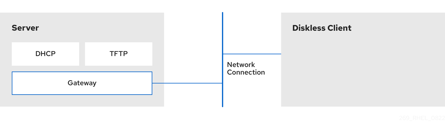
20.1. Preparing environments for the remote diskless system
Prepare your environment to be able to continue with remote diskless system implementation. The remote diskless system booting requires a Trivial File Transfer Protocol (TFTP) service (provided by tftp-server) and a Dynamic Host Configuration Protocol (DHCP) service (provided by dhcp). The system uses the tftp service to retrieve the kernel image and the initial RAM disk, initrd, over the network, through the Preboot Execution Environment (PXE) loader.
To ensure correct functionality of the remote diskless system in your environment, configure services in the following order:
-
tftpservice for diskless clients - the DHCP server
- the Network File System (NFS)
- the exported file system.
Prerequisites
You have installed the following package:
-
xinetd
-
- You have set up your network connection.
Procedure
Install the
dracut-networkpackage:# yum install dracut-networkAdd the following line to the
/etc/dracut.conf.d/network.conffile:add_dracutmodules+=" nfs "
20.2. Configuring a TFTP service for diskless clients
For the remote diskless system to function correctly in your environment, you need to first configure a Trivial File Transfer Protocol (TFTP) service for diskless clients.
This configuration does not boot over the Unified Extensible Firmware Interface (UEFI). For UEFI based installation. see Configuring a TFTP server for UEFI-based clients.
Prerequisites
You have installed the following packages:
-
tftp-server -
syslinux -
xinetd
-
Procedure
Enable the
tftpservice:# systemctl enable --now tftp
Create a
pxelinuxdirectory inside thetftproot directory:# mkdir -p /var/lib/tftpboot/pxelinux/
Copy the
/usr/share/syslinux/pxelinux.0file to the/var/lib/tftpboot/pxelinux/directory:# cp /usr/share/syslinux/pxelinux.0 /var/lib/tftpboot/pxelinux/
-
You can find the tftp root directory (
chroot) in the/var/lib/tftpbootdirectory.
-
You can find the tftp root directory (
Copy
/usr/share/syslinux/ldlinux.c32to/var/lib/tftpboot/pxelinux/:# cp /usr/share/syslinux/ldlinux.c32 /var/lib/tftpboot/pxelinux/
Create a
pxelinux.cfgdirectory inside thetftproot directory:# mkdir -p /var/lib/tftpboot/pxelinux/pxelinux.cfg/
This configuration does not boot over the Unified Extensible Firmware Interface (UEFI). To perform the installation for UEFI, follow the procedure in Configuring a TFTP server for UEFI-based clients.
Verification
Check status of service
tftp:# systemctl status tftp ... Active: active (running) ...
20.3. Configuring a DHCP server for diskless clients
The remote diskless system requires several pre–installed services to enable correct functionality. First, you need to install the Trivial File Transfer Protocol (TFTP) service, and then configure the Dynamic Host Configuration Protocol (DHCP) server.
Prerequisites
You have installed the following packages:
-
dhcp-server -
xinetd
-
-
You have configured the
tftpservice for diskless clients. See section Configuring a TFTP service for diskless clients.
Procedure
Add the configuration to the
/etc/dhcp/dhcpd.conffile to setup a DHCP server and enable Preboot Execution Environment (PXE) for booting:option space pxelinux; option pxelinux.magic code 208 = string; option pxelinux.configfile code 209 = text; option pxelinux.pathprefix code 210 = text; option pxelinux.reboottime code 211 = unsigned integer 32; option architecture-type code 93 = unsigned integer 16; subnet 192.168.205.0 netmask 255.255.255.0 { option routers 192.168.205.1; range 192.168.205.10 192.168.205.25; class "pxeclients" { match if substring (option vendor-class-identifier, 0, 9) = "PXEClient"; next-server 192.168.205.1; if option architecture-type = 00:07 { filename "BOOTX64.efi"; } else { filename "pxelinux/pxelinux.0"; } } }Your DHCP configuration might be different depending on your environment, like setting lease time or fixed address. For details, see Providing DHCP services.
NoteWhile using
libvirtvirtual machine as a diskless client, thelibvirtdaemon provides the DHCP service, and the standalone DHCP server is not used. In this situation, network booting must be enabled with thebootp file=<filename>option in thelibvirtnetwork configuration,virsh net-edit.
Enable
dhcpd.service:# systemctl enable --now dhcpd.service
Verification
Check the status of service
dhcpd.service:# systemctl status dhcpd.service ... Active: active (running) ...
20.4. Configuring an exported file system for diskless clients
As a part of configuring a remote diskless system in your environment, you must configure an exported file system for diskless clients.
Prerequisites
-
You have configured the
tftpservice for diskless clients. See section Configuring a TFTP service for diskless clients. - You have configured the Dynamic Host Configuration Protocol (DHCP) server. See section Configuring a DHCP server for diskless clients.
Procedure
Configure the Network File System (NFS) server to export the root directory by adding it to the
/etc/exportsdirectory. For the complete set of instructions seeInstall a complete version of Red Hat Enterprise Linux to the root directory to accommodate completely diskless clients. To do that you can either install a new base system or clone an existing installation.
Install Red Hat Enterprise Linux to the exported location by replacing exported-root-directory with the path to the exported file system:
# yum install @Base kernel dracut-network nfs-utils --installroot=exported-root-directory --releasever=/By setting the
releaseveroption to/, releasever is detected from the host (/) system.Use the
rsyncutility to synchronize with a running system:# rsync -a -e ssh --exclude='/proc/' --exclude='/sys/' example.com:/ exported-root-directory-
Replace example.com with the hostname of the running system with which to synchronize via the
rsyncutility. Replace exported-root-directory with the path to the exported file system.
Note, that for this option you must have a separate existing running system, which you will clone to the server by the command above.
-
Replace example.com with the hostname of the running system with which to synchronize via the
You need to fully configure the file system, that is ready for export, before you can use it with diskless clients. Follow the procedure below to complete the configuration.
Configuring a File System
Copy the diskless client supported kernel (
vmlinuz-_kernel-version_pass:attributes) to thetftpboot directory:# cp /exported-root-directory/boot/vmlinuz-kernel-version /var/lib/tftpboot/pxelinux/Create the
initramfs-kernel-version.imgfile locally and move it to the exported root directory with NFS support:# dracut --add nfs initramfs-kernel-version.img kernel-versionFor example:
# dracut --add nfs /exports/root/boot/initramfs-5.14.0-202.el9.x86_64.img 5.14.0-202.el9.x86_64Example for creating initrd, using current running kernel version, and overwriting existing image:
# dracut -f --add nfs "boot/initramfs-$(uname -r).img" "$(uname -r)"Change the file permissions for
initrdto0644:# chmod 0644 /exported-root-directory/boot/initramfs-kernel-version.imgWarningIf you do not change the
initrdfile permissions, thepxelinux.0boot loader fails with a "file not found" error.Copy the resulting
initramfs-kernel-version.imgfile into thetftpboot directory:# cp /exported-root-directory/boot/initramfs-kernel-version.img /var/lib/tftpboot/pxelinux/Add the following configuration in the
/var/lib/tftpboot/pxelinux/pxelinux.cfg/defaultfile to edit the default boot configuration for using theinitrdand the kernel:default menu.c32 prompt 0 menu title PXE Boot Menu ontimeout rhel8-over-nfsv4.2 timeout 120 label rhel8-over-nfsv4.2 menu label Install diskless rhel8{} nfsv4.2{} kernel $vmlinuz append initrd=$initramfs root=nfs4:$nfsserv:/:vers=4.2,rw rw panic=60 ipv6.disable=1 console=tty0 console=ttyS0,115200n8 label rhel8-over-nfsv3 menu label Install diskless rhel8{} nfsv3{} kernel $vmlinuz append initrd=$initramfs root=nfs:$nfsserv:$nfsroot:vers=3,rw rw panic=60 ipv6.disable=1 console=tty0 console=ttyS0,115200n8-
This configuration instructs the diskless client root to mount the exported file system (
/exported-root-directory) in a read/write format.
-
This configuration instructs the diskless client root to mount the exported file system (
Optional: Mount the file system in a read-only format by editing the
/var/lib/tftpboot/pxelinux/pxelinux.cfg/defaultfile with the following configuration:default rhel8 label rhel8 kernel vmlinuz-kernel-version append initrd=initramfs-kernel-version.img root=nfs:server-ip:/exported-root-directory ro
Restart the NFS server:
# systemctl restart nfs-server.service
You can now export the NFS share to diskless clients. These clients can boot over the network via Preboot Execution Environment (PXE).
20.5. Re-configuring a remote diskless system
If you want to install package updates, service restart, or debug the issues, you can reconfigure the system. The steps below show how to change the password for a user, how to install software on a system, describe how to split a system into a /usr that is in read-only mode and a /var that is in read-write mode.
Prerequisites
-
You have enabled the
no_root_squashoption in the exported file system.
Procedure
To change the user password, follow the steps below:
Change the command line to /exported/root/directory:
# chroot /exported/root/directory /bin/bashChange the password for the user you want:
# passwd <username>Replace the <username> with a real user to whom you want to change the password.
- Exit the command line.
Install software on a remote diskless system:
# yum install <package> --installroot=/exported/root/directory --releasever=/ --config /etc/dnf/dnf.conf --setopt=reposdir=/etc/yum.repos.d/- Replace <package> with the actual package you want to install.
Configure two separate exports to split a remote diskless system into a /usr and a /var. See
20.6. Troubleshooting common issues with loading a remote diskless system
Based on the earlier configuration, some issues can occur while loading the remote diskless system. Following are some examples of the most common issues and ways to troubleshoot them on a Red Hat Enterprise Linux server.
Example 20.1. The client does not get an IP address
Check if the Dynamic Host Configuration Protocol (DHCP) service is enabled on the server.
Check if the
dhcp.serviceis running:# systemctl status dhcpd.serviceIf the
dhcp.serviceis inactive, you must enable and start it:# systemctl enable dhcpd.service # systemctl start dhcpd.service
- Reboot the diskless client.
-
Check the DHCP configuration file
/etc/dhcp/dhcpd.conf. For details, see Configuring a DHCP server for diskless clients.
Check if the Firewall ports are opened.
Check if the
dhcp.serviceis listed in active services:# firewall-cmd --get-active-zones # firewall-cmd --info-zone=public
If the
dhcp.serviceis not listed in active services, add it to the list:# firewall-cmd --add-service=dhcp --permanentCheck if the
nfs.serviceis listed in active services:# firewall-cmd --get-active-zones # firewall-cmd --info-zone=public
If the
nfs.serviceis not listed in active services, add it to the list:# firewall-cmd --add-service=nfs --permanent
Example 20.2. The file is not available during the booting a remote diskless system
-
Check if the file is in the
/var/lib/tftpboot/directory. If the file is in the directory, check the permission:
# chmod 644 pxelinux.0- Check if the Firewall ports are opened.
Example 20.3. System boot failed after loading kernel/initrd
Check if the NFS service is enabled on a server.
Check if
nfs.serviceis running:# systemctl status nfs.serviceIf the
nfs.serviceis inactive, you must start and enable it:# systemctl start nfs.service # systemctl enable nfs.service
-
Check if the parameters are correct in the
/var/lib/tftpboot/pxelinux.cfg/directory. For details, see Configuring an exported file system for diskless clients. - Check if the Firewall ports are opened.
Chapter 21. Managing RAID
You can use a Redundant Array of Independent Disks (RAID) to store data across multiple drives. It can help to avoid data loss if a drive has failed.
21.1. Overview of RAID
In a RAID, multiple devices, such as HDD, SSD, or NVMe are combined into an array to accomplish performance or redundancy goals not achievable with one large and expensive drive. This array of devices appears to the computer as a single logical storage unit or drive.
RAID supports various configurations, including levels 0, 1, 4, 5, 6, 10, and linear. RAID uses techniques such as disk striping (RAID Level 0), disk mirroring (RAID Level 1), and disk striping with parity (RAID Levels 4, 5 and 6) to achieve redundancy, lower latency, increased bandwidth, and maximized ability to recover from hard disk crashes.
RAID distributes data across each device in the array by breaking it down into consistently-sized chunks, commonly 256 KB or 512 KB, although other values are acceptable. It writes these chunks to a hard drive in the RAID array according to the RAID level employed. While reading the data, the process is reversed, giving the illusion that the multiple devices in the array are actually one large drive.
RAID technology is beneficial for those who manage large amounts of data. The following are the primary reasons to deploy RAID:
- It enhances speed
- It increases storage capacity using a single virtual disk
- It minimizes data loss from disk failure
- The RAID layout and level online conversion
21.2. RAID types
The following are the possible types of RAID:
- Firmware RAID
- Firmware RAID, also known as ATARAID, is a type of software RAID where the RAID sets can be configured using a firmware-based menu. The firmware used by this type of RAID also hooks into the BIOS, allowing you to boot from its RAID sets. Different vendors use different on-disk metadata formats to mark the RAID set members. The Intel Matrix RAID is an example of a firmware RAID system.
- Hardware RAID
A hardware-based array manages the RAID subsystem independently from the host. It might present multiple devices per RAID array to the host.
Hardware RAID devices might be internal or external to the system. Internal devices commonly consists of a specialized controller card that handles the RAID tasks transparently to the operating system. External devices commonly connect to the system via SCSI, Fibre Channel, iSCSI, InfiniBand, or other high speed network interconnect and present volumes such as logical units to the system.
RAID controller cards function like a SCSI controller to the operating system and handle all the actual drive communications. You can plug the drives into the RAID controller similar to a normal SCSI controller and then add them to the RAID controller’s configuration. The operating system will not be able to tell the difference.
- Software RAID
A software RAID implements the various RAID levels in the kernel block device code. It offers the cheapest possible solution because expensive disk controller cards or hot-swap chassis are not required. With hot-swap chassis, you can remove a hard drive without powering off your system. Software RAID also works with any block storage, which are supported by the Linux kernel, such as SATA, SCSI, and NVMe. With today’s faster CPUs, Software RAID also generally outperforms hardware RAID, unless you use high-end storage devices.
Since the Linux kernel contains a multiple device (MD) driver, the RAID solution becomes completely hardware independent. The performance of a software-based array depends on the server CPU performance and load.
The following are the key features of the Linux software RAID stack:
- Multithreaded design
- Portability of arrays between Linux machines without reconstruction
- Backgrounded array reconstruction using idle system resources
- Hot-swap drive support
- Automatic CPU detection to take advantage of certain CPU features such as streaming Single Instruction Multiple Data (SIMD) support.
- Automatic correction of bad sectors on disks in an array.
- Regular consistency checks of RAID data to ensure the health of the array.
- Proactive monitoring of arrays with email alerts sent to a designated email address on important events.
Write-intent bitmaps, which drastically increase the speed of resync events by allowing the kernel to know precisely which portions of a disk need to be resynced instead of having to resync the entire array after a system crash.
NoteThe resync is a process to synchronize the data over the devices in the existing RAID to achieve redundancy.
- Resync checkpointing so that if you reboot your computer during a resync, at startup the resync resumes where it left off and not starts all over again.
- The ability to change parameters of the array after installation, which is called reshaping. For example, you can grow a 4-disk RAID5 array to a 5-disk RAID5 array when you have a new device to add. This grow operation is done live and does not require you to reinstall on the new array.
- Reshaping supports changing the number of devices, the RAID algorithm or size of the RAID array type, such as RAID4, RAID5, RAID6, or RAID10.
- Takeover supports RAID level conversion, such as RAID0 to RAID6.
- Cluster MD, which is a storage solution for a cluster, provides the redundancy of RAID1 mirroring to the cluster. Currently, only RAID1 is supported.
21.3. RAID levels and linear support
The following are the supported configurations by RAID, including levels 0, 1, 4, 5, 6, 10, and linear:
- Level 0
RAID level 0, often called striping, is a performance-oriented striped data mapping technique. This means the data being written to the array is broken down into stripes and written across the member disks of the array, allowing high I/O performance at low inherent cost but provides no redundancy.
RAID level 0 implementations only stripe the data across the member devices up to the size of the smallest device in the array. This means that if you have multiple devices with slightly different sizes, each device gets treated as though it was the same size as the smallest drive. Therefore, the common storage capacity of a level 0 array is the total capacity of all disks. If the member disks have a different size, then the RAID0 uses all the space of those disks using the available zones.
- Level 1
RAID level 1, or mirroring, provides redundancy by writing identical data to each member disk of the array, leaving a mirrored copy on each disk. Mirroring remains popular due to its simplicity and high level of data availability. Level 1 operates with two or more disks, and provides very good data reliability and improves performance for read-intensive applications but at relatively high costs.
RAID level 1 is costly because you write the same information to all of the disks in the array, which provides data reliability, but in a much less space-efficient manner than parity based RAID levels such as level 5. However, this space inefficiency comes with a performance benefit, which is parity-based RAID levels that consume considerably more CPU power in order to generate the parity while RAID level 1 simply writes the same data more than once to the multiple RAID members with very little CPU overhead. As such, RAID level 1 can outperform the parity-based RAID levels on machines where software RAID is employed and CPU resources on the machine are consistently taxed with operations other than RAID activities.
The storage capacity of the level 1 array is equal to the capacity of the smallest mirrored hard disk in a hardware RAID or the smallest mirrored partition in a software RAID. Level 1 redundancy is the highest possible among all RAID types, with the array being able to operate with only a single disk present.
- Level 4
Level 4 uses parity concentrated on a single disk drive to protect data. Parity information is calculated based on the content of the rest of the member disks in the array. This information can then be used to reconstruct data when one disk in the array fails. The reconstructed data can then be used to satisfy I/O requests to the failed disk before it is replaced and to repopulate the failed disk after it has been replaced.
Since the dedicated parity disk represents an inherent bottleneck on all write transactions to the RAID array, level 4 is seldom used without accompanying technologies such as write-back caching. Or it is used in specific circumstances where the system administrator is intentionally designing the software RAID device with this bottleneck in mind such as an array that has little to no write transactions once the array is populated with data. RAID level 4 is so rarely used that it is not available as an option in Anaconda. However, it could be created manually by the user if needed.
The storage capacity of hardware RAID level 4 is equal to the capacity of the smallest member partition multiplied by the number of partitions minus one. The performance of a RAID level 4 array is always asymmetrical, which means reads outperform writes. This is because write operations consume extra CPU resources and main memory bandwidth when generating parity, and then also consume extra bus bandwidth when writing the actual data to disks because you are not only writing the data, but also the parity. Read operations need only read the data and not the parity unless the array is in a degraded state. As a result, read operations generate less traffic to the drives and across the buses of the computer for the same amount of data transfer under normal operating conditions.
- Level 5
This is the most common type of RAID. By distributing parity across all the member disk drives of an array, RAID level 5 eliminates the write bottleneck inherent in level 4. The only performance bottleneck is the parity calculation process itself. Modern CPUs can calculate parity very fast. However, if you have a large number of disks in a RAID 5 array such that the combined aggregate data transfer speed across all devices is high enough, parity calculation can be a bottleneck.
Level 5 has asymmetrical performance, and reads substantially outperforming writes. The storage capacity of RAID level 5 is calculated the same way as with level 4.
- Level 6
This is a common level of RAID when data redundancy and preservation, and not performance, are the paramount concerns, but where the space inefficiency of level 1 is not acceptable. Level 6 uses a complex parity scheme to be able to recover from the loss of any two drives in the array. This complex parity scheme creates a significantly higher CPU burden on software RAID devices and also imposes an increased burden during write transactions. As such, level 6 is considerably more asymmetrical in performance than levels 4 and 5.
The total capacity of a RAID level 6 array is calculated similarly to RAID level 5 and 4, except that you must subtract two devices instead of one from the device count for the extra parity storage space.
- Level 10
This RAID level attempts to combine the performance advantages of level 0 with the redundancy of level 1. It also reduces some of the space wasted in level 1 arrays with more than two devices. With level 10, it is possible, for example, to create a 3-drive array configured to store only two copies of each piece of data, which then allows the overall array size to be 1.5 times the size of the smallest devices instead of only equal to the smallest device, similar to a 3-device, level 1 array. This avoids CPU process usage to calculate parity similar to RAID level 6, but it is less space efficient.
The creation of RAID level 10 is not supported during installation. It is possible to create one manually after installation.
- Linear RAID
Linear RAID is a grouping of drives to create a larger virtual drive.
In linear RAID, the chunks are allocated sequentially from one member drive, going to the next drive only when the first is completely filled. This grouping provides no performance benefit, as it is unlikely that any I/O operations split between member drives. Linear RAID also offers no redundancy and decreases reliability. If any one member drive fails, the entire array cannot be used and data can be lost. The capacity is the total of all member disks.
21.4. Linux RAID subsystems
The following subsystems compose RAID in Linux:
- Linux Hardware RAID Controller Drivers
- Hardware RAID controllers have no specific RAID subsystem in Linux. Since they use special RAID chipsets, hardware RAID controllers come with their own drivers. With these drivers, the system detects the RAID sets as regular disks.
mdraidThe
mdraidsubsystem was designed as a software RAID solution for Linux. It is also the preferred solution for software RAID in Red Hat Enterprise Linux. This subsystem uses its own metadata format, which is referred to as native MD metadata.It also supports other metadata formats, known as external metadata. Red Hat Enterprise Linux 8 uses
mdraidwith external metadata to access Intel Rapid Storage (ISW) or Intel Matrix Storage Manager (IMSM) sets and Storage Networking Industry Association (SNIA) Disk Drive Format (DDF). Themdraidsubsystem sets are configured and controlled through themdadmutility.
21.5. Creating a software RAID during the installation
Redundant Arrays of Independent Disks (RAID) devices are constructed from multiple storage devices that are arranged to provide increased performance and, in some configurations, greater fault tolerance.
A RAID device is created in one step and disks are added or removed as necessary. You can configure one RAID partition for each physical disk in your system, so that the number of disks available to the installation program determines the levels of RAID device available. For example, if your system has two disks, you cannot create a RAID 10 device, as it requires a minimum of three separate disks.
On 64-bit IBM Z, the storage subsystem uses RAID transparently. You do not have to configure software RAID manually.
Prerequisites
- You have selected two or more disks for installation before RAID configuration options are visible. Depending on the RAID type you want to create, at least two disks are required.
- You have created a mount point. By configuring a mount point, you can configure the RAID device.
- You have selected the radio button on the Installation Destination window.
Procedure
- From the left pane of the Manual Partitioning window, select the required partition.
- Under the Device(s) section, click . The Configure Mount Point dialog box opens.
- Select the disks that you want to include in the RAID device and click .
- Click the Device Type drop-down menu and select RAID.
- Click the File System drop-down menu and select your preferred file system type.
- Click the RAID Level drop-down menu and select your preferred level of RAID.
- Click to save your changes.
- Click to apply the settings to return to the Installation Summary window.
Additional resources
21.6. Creating a software RAID on an installed system
You can create a software Redundant Array of Independent Disks (RAID) on an existing system using the mdadm utility.
Prerequisites
-
The
mdadmpackage is installed. - You have created two or more partitions on your system. For detailed instructions, see Creating a partition with parted.
Procedure
Create a RAID of two block devices, for example /dev/sda1 and /dev/sdc1:
# mdadm --create /dev/md0 --level=0 --raid-devices=2 /dev/sda1 /dev/sdc1
mdadm: Defaulting to version 1.2 metadata
mdadm: array /dev/md0 started.
The level_value option defines the RAID level.
Optional: Check the status of the RAID:
# mdadm --detail /dev/md0
/dev/md0:
           Version : 1.2
     Creation Time : Thu Oct 13 15:17:39 2022
        Raid Level : raid0
        Array Size : 18649600 (17.79 GiB 19.10 GB)
      Raid Devices : 2
     Total Devices : 2
       Persistence : Superblock is persistent

       Update Time : Thu Oct 13 15:17:39 2022
             State : clean
    Active Devices : 2
   Working Devices : 2
    Failed Devices : 0
     Spare Devices : 0
[...]
Optional: Observe the detailed information about each device in the RAID:
# mdadm --examine /dev/sda1 /dev/sdc1
/dev/sda1:
          Magic : a92b4efc
        Version : 1.2
    Feature Map : 0x1000
     Array UUID : 77ddfb0a:41529b0e:f2c5cde1:1d72ce2c
           Name : 0
  Creation Time : Thu Oct 13 15:17:39 2022
     Raid Level : raid0
   Raid Devices : 2
[...]
Create a file system on the RAID drive:
# mkfs -t xfs /dev/md0Replace xfs with the file system that you chose to format the drive with.
Create a mount point for RAID drive and mount it:
# mkdir /mnt/raid1
# mount /dev/md0 /mnt/raid1
Replace /mnt/raid1 with the mount point.
If you want that RHEL mounts the
md0RAID device automatically when the system boots, add an entry for your device to the/etc/fstab file:/dev/md0 /mnt/raid1 xfs defaults 0 0
21.7. Configuring a RAID volume using the storage System Role
With the storage System Role, you can configure a RAID volume on RHEL using Red Hat Ansible Automation Platform and Ansible-Core. Create an Ansible playbook with the parameters to configure a RAID volume to suit your requirements.
Prerequisites
- The Ansible Core package is installed on the control machine.
-
You have the
rhel-system-rolespackage installed on the system from which you want to run the playbook. -
You have an inventory file detailing the systems on which you want to deploy a RAID volume using the
storageSystem Role.
Procedure
Create a new playbook.yml file with the following content:
--- - name: Configure the storage hosts: managed-node-01.example.com tasks: - name: Create a RAID on sdd, sde, sdf, and sdg include_role: name: rhel-system-roles.storage vars: storage_safe_mode: false storage_volumes: - name: data type: raid disks: [sdd, sde, sdf, sdg] raid_level: raid0 raid_chunk_size: 32 KiB mount_point: /mnt/data state: presentWarningDevice names might change in certain circumstances, for example, when you add a new disk to a system. Therefore, to prevent data loss, do not use specific disk names in the playbook.
Optional: Verify the playbook syntax:
# ansible-playbook --syntax-check playbook.ymlRun the playbook:
# ansible-playbook -i inventory.file /path/to/file/playbook.yml
Additional resources
-
The
/usr/share/ansible/roles/rhel-system-roles.storage/README.mdfile - Preparing a control node and managed nodes to use RHEL System Roles
21.8. Extending RAID
You can extend a RAID using the --grow option of the mdadm utility.
Prerequisites
- Enough disk space.
-
The
partedpackage is installed.
Procedure
- Extend RAID partitions. For more information, see Resizing a partition with parted.
Extend RAID to the maximum of the partition capacity:
# mdadm --grow --size=max /dev/md0
To set a specific size, write the value of the
--sizeparameter in kB, for example--size=524228.Increase the size of file system. For example, if the volume uses XFS and is mounted to /mnt/, enter:
# xfs_growfs /mnt/
Additional resources
-
The
mdadm(8)man page - Managing file systems
21.9. Shrinking RAID
You can shrink RAID using the --grow option of the mdadm utility.
The XFS file system does not support shrinking.
Prerequisites
-
The
partedpackage is installed.
Procedure
- Shrink the file system. For more information, see Managing file systems.
Decrease the RAID to the size, for example to 512 MB:
# mdadm --grow --size=524228 /dev/md0Write the
--sizeparameter in kB.- Shrink the partition to the size you need.
Additional resources
-
The
mdadm(8)man page - Resizing a partition with parted.
21.10. Supported RAID conversions
It is possible to convert from one RAID level to another. For example, you can convert from RAID5 to RAID10, but not from RAID10 to RAID5. The following table describes the supported RAID conversions:
| Source level | Destination level |
|---|---|
| RAID0 | RAID4, RAID5, RAID10 |
| RAID1 | RAID0, RAID5 |
| RAID4 | RAID0, RAID5 |
| RAID5 | RAID0, RAID1, RAID4, RAID6, RAID10 |
| RAID6 | RAID5 |
| RAID10 | RAID0 |
Converting RAID 5 to RAID0 and RAID4 is only possible with the ALGORITHM_PARITY_N layout.
Additional resources.
-
The
mdadm(8)man page
21.11. Converting a RAID level
You can convert RAID to a different RAID level as required. The following example converts the RAID device /dev/md0 with level 0 to 5 and add one more disk /dev/sdd to the array.
Prerequisites
- Enough disks for conversion.
-
The
mdadmpackage is installed. - Ensure the intended conversion is supported. See Supported RAID conversions.
Procedure
Convert the RAID /dev/md0 to RAID level 5:
# mdadm --grow --level=5 -n 3 /dev/md0 --forceAdd a new disk to the array:
# mdadm --manage /dev/md0 --add /dev/sdd
Verification
Verify if the RAID level is converted:
# mdadm --detail /dev/md0
/dev/md0:
           Version : 1.2
     Creation Time : Thu Oct 13 15:17:39 2022
        Raid Level : raid0
        Array Size : 18649600 (17.79 GiB 19.10 GB)
      Raid Devices : 5
[...]
Additional resources
-
The
mdadm(8)man page
21.12. Converting a root disk to RAID1 after installation
This section describes how to convert a non-RAID root disk to a RAID1 mirror after installing Red Hat Enterprise Linux 8.
On the PowerPC (PPC) architecture, take the following additional steps:
Prerequisites
- The instructions in the following Red Hat Knowledgebase article are completed: How do I convert my root disk to RAID1 after installation of Red Hat Enterprise Linux 7?.
Procedure
Copy the contents of the PowerPC Reference Platform (PReP) boot partition from /dev/sda1 to /dev/sdb1:
# dd if=/dev/sda1 of=/dev/sdb1
Update the
prepandbootflag on the first partition on both disks:$ parted /dev/sda set 1 prep on $ parted /dev/sda set 1 boot on $ parted /dev/sdb set 1 prep on $ parted /dev/sdb set 1 boot on
Executing the grub2-install /dev/sda command does not work on a PowerPC machine and returns an error, but the system boots as expected.
21.13. Creating advanced RAID devices
In some cases, you might want to install the operating system on an array that is created before the installation completes. Usually, this means setting up the /boot or root file system arrays on a complex RAID device. In such cases, you might need to use array options that are not supported by the Anaconda installer. To work around this, perform the following steps.
The limited Rescue Mode of the installer does not include man pages. Both the mdadm and md man pages contain useful information for creating custom RAID arrays, and might be needed throughout the workaround.
Procedure
- Insert the install disk.
-
During the initial boot up, select Rescue Mode instead of Install or Upgrade. When the system fully boots into
Rescue mode, you can see the command line terminal. From this terminal, execute the following commands:
-
Create RAID partitions on the target hard drives by using the
partedcommand. -
Manually create raid arrays by using the
mdadmcommand from those partitions using any and all settings and options available.
-
Create RAID partitions on the target hard drives by using the
- Optional: After creating arrays, create file systems on the arrays as well.
- Reboot the computer and select Install or Upgrade to install. As the Anaconda installer searches the disks in the system, it finds the pre-existing RAID devices.
- When asked about how to use the disks in the system, select Custom Layout and click . In the device listing, the pre-existing MD RAID devices are listed.
- Select a RAID device and click .
- Configure its mount point and optionally the type of file system it should use if you did not create one earlier, and then click . Anaconda installs to this pre-existing RAID device, preserving the custom options you selected when you created it in Rescue Mode.
21.14. Setting up email notifications to monitor a RAID
You can set up email alerts to monitor RAID with the mdadm tool. Once the MAILADDR variable is set to the required email address, the monitoring system sends the alerts to the added email address.
Prerequisites
-
The
mdadmpackage is installed. - The mail service is set up.
Procedure
Create the
/etc/mdadm.confconfiguration file for monitoring array by scanning the RAID details:# mdadm --detail --scan >> /etc/mdadm.conf
Note, that
ARRAYandMAILADDRare mandatory variables.Open the
/etc/mdadm.confconfiguration file with a text editor of your choice and add theMAILADDRvariable with the mail address for the notification. For example, add new line:MAILADDR example@example.comHere, example@example.com is an email address to which you want to receive the alerts from the array monitoring.
-
Save changes in the
/etc/mdadm.conffile and close it.
Additional resources
-
The
mdadm.conf(5)man page
21.15. Replacing a failed disk in RAID
You can reconstruct the data from the failed disks using the remaining disks. RAID level and the total number of disks determines the minimum amount of remaining disks needed for a successful data reconstruction.
In this procedure, the /dev/md0 RAID contains four disks. The /dev/sdd disk has failed and you need to replace it with the /dev/sdf disk.
Prerequisites
- A spare disk for replacement.
-
The
mdadmpackage is installed.
Procedure
Check the failed disk:
View the kernel logs:
# journalctl -k -f
Search for a message similar to the following:
md/raid:md0: Disk failure on sdd, disabling device.

md/raid:md0: Operation continuing on 3 devices.
-
Press Ctrl+C on your keyboard to exit the
journalctlprogram.
Mark the failed disk as faulty:
# mdadm --manage /dev/md0 --fail /dev/sdd
Optional: Check if the failed disk was marked correctly:
# mdadm --detail /dev/md0At the end of the output is a list of disks in the /dev/md0 RAID where the disk /dev/sdd has the faulty status:
Number   Major   Minor   RaidDevice State
   0       8       16        0      active sync   /dev/sdb
   1       8       32        1      active sync   /dev/sdc
   -       0        0        2      removed
   3       8       64        3      active sync   /dev/sde

   2       8       48        -      faulty   /dev/sdd
Remove the failed disk from the RAID:
# mdadm --manage /dev/md0 --remove /dev/sdd
WarningIf your RAID cannot withstand another disk failure, do not remove any disk until the new disk has the active sync status. You can monitor the progress using the
watch cat /proc/mdstatcommand.Add the new disk to the RAID:
# mdadm --manage /dev/md0 --add /dev/sdf
The /dev/md0 RAID now includes the new disk /dev/sdf and the
mdadmservice will automatically starts copying data to it from other disks.
Verification
Check the details of the array:
# mdadm --detail /dev/md0If this command shows a list of disks in the /dev/md0 RAID where the new disk has spare rebuilding status at the end of the output, data is still being copied to it from other disks:
Number   Major   Minor   RaidDevice State
   0       8       16        0      active sync   /dev/sdb
   1       8       32        1      active sync   /dev/sdc
   4       8       80        2      spare rebuilding   /dev/sdf
   3       8       64        3      active sync   /dev/sde
After data copying is finished, the new disk has an active sync status.
Additional resources
21.16. Repairing RAID disks
This procedure describes how to repair disks in a RAID array.
Prerequisites
-
The
mdadmpackage is installed.
Procedure
Check the array for the failed disks behavior:
# echo check > /sys/block/md0/md/sync_actionThis checks the array and the
/sys/block/md0/md/sync_actionfile shows the sync action.-
Open the
/sys/block/md0/md/sync_actionfile with the text editor of your choice and see if there is any message about disk synchronization failures. -
View the
/sys/block/md0/md/mismatch_cntfile. If themismatch_cntparameter is not0, it means that the RAID disks need repair. Repair the disks in the array:
# echo repair > /sys/block/md0/md/sync_actionThis repairs the disks in the array and writes the result into the
/sys/block/md0/md/sync_actionfile.View the synchronization progress:
# cat /sys/block/md0/md/sync_action
repair

# cat /proc/mdstat
Personalities : [raid0] [raid6] [raid5] [raid4] [raid1]
md0 : active raid1 sdg[1] dm-3[0]
      511040 blocks super 1.2 [2/2] [UU]
unused devices: <none>
Chapter 22. Encrypting block devices using LUKS
By using the disk encryption, you can protect the data on a block device by encrypting it. To access the device’s decrypted contents, enter a passphrase or key as authentication. This is important for mobile computers and removable media because it helps to protect the device’s contents even if it has been physically removed from the system. The LUKS format is a default implementation of block device encryption in Red Hat Enterprise Linux.
22.1. LUKS disk encryption
Linux Unified Key Setup-on-disk-format (LUKS) provides a set of tools that simplifies managing the encrypted devices. With LUKS, you can encrypt block devices and enable multiple user keys to decrypt a master key. For bulk encryption of the partition, use this master key.
Red Hat Enterprise Linux uses LUKS to perform block device encryption. By default, the option to encrypt the block device is unchecked during the installation. If you select the option to encrypt your disk, the system prompts you for a passphrase every time you boot the computer. This passphrase unlocks the bulk encryption key that decrypts your partition. If you want to modify the default partition table, you can select the partitions that you want to encrypt. This is set in the partition table settings.
Ciphers
The default cipher used for LUKS is aes-xts-plain64. The default key size for LUKS is 512 bits. The default key size for LUKS with Anaconda XTS mode is 512 bits. The following are the available ciphers:
- Advanced Encryption Standard (AES)
- Twofish
- Serpent
Operations performed by LUKS
- LUKS encrypts entire block devices and is therefore well-suited for protecting contents of mobile devices such as removable storage media or laptop disk drives.
- The underlying contents of the encrypted block device are arbitrary, which makes it useful for encrypting swap devices. This can also be useful with certain databases that use specially formatted block devices for data storage.
- LUKS uses the existing device mapper kernel subsystem.
- LUKS provides passphrase strengthening, which protects against dictionary attacks.
- LUKS devices contain multiple key slots, which means you can add backup keys or passphrases.
LUKS is not recommended for the following scenarios:
- Disk-encryption solutions such as LUKS protect the data only when your system is off. After the system is on and LUKS has decrypted the disk, the files on that disk are available to anyone who have access to them.
- Scenarios that require multiple users to have distinct access keys to the same device. The LUKS1 format provides eight key slots and LUKS2 provides up to 32 key slots.
- Applications that require file-level encryption.
22.2. LUKS versions in RHEL
In Red Hat Enterprise Linux, the default format for LUKS encryption is LUKS2. The old LUKS1 format remains fully supported and it is provided as a format compatible with earlier Red Hat Enterprise Linux releases. LUKS2 re-encryption is considered more robust and safe to use as compared to LUKS1 re-encryption.
The LUKS2 format enables future updates of various parts without a need to modify binary structures. Internally it uses JSON text format for metadata, provides redundancy of metadata, detects metadata corruption, and automatically repairs from a metadata copy.
Do not use LUKS2 in systems that support only LUKS1 because LUKS2 and LUKS1 use different commands to encrypt the disk. Using the wrong command for a LUKS version might cause data loss.
Table 22.1. Encryption commands depending on the LUKS version
| LUKS version | Encryption command |
|---|---|
| LUKS2 |
|
| LUKS1 |
|
Online re-encryption
The LUKS2 format supports re-encrypting encrypted devices while the devices are in use. For example, you do not have to unmount the file system on the device to perform the following tasks:
- Changing the volume key
Changing the encryption algorithm
When encrypting a non-encrypted device, you must still unmount the file system. You can remount the file system after a short initialization of the encryption.
The LUKS1 format does not support online re-encryption.
Conversion
In certain situations, you can convert LUKS1 to LUKS2. The conversion is not possible specifically in the following scenarios:
-
A LUKS1 device is marked as being used by a Policy-Based Decryption (PBD) Clevis solution. The
cryptsetuptool does not convert the device when someluksmetametadata are detected. - A device is active. The device must be in an inactive state before any conversion is possible.
22.3. Options for data protection during LUKS2 re-encryption
LUKS2 provides several options that prioritize performance or data protection during the re-encryption process. It provides the following modes for the resilience option, and you can select any of these modes by using the cryptsetup reencrypt --resilience resilience-mode /dev/sdx command:
checksumThe default mode. It balances data protection and performance.
This mode stores individual checksums of the sectors in the re-encryption area, which the recovery process can detect for the sectors that were re-encrypted by LUKS2. The mode requires that the block device sector write is atomic.
journal- The safest mode but also the slowest. Since this mode journals the re-encryption area in the binary area, the LUKS2 writes the data twice.
none-
The
nonemode prioritizes performance and provides no data protection. It protects the data only against safe process termination, such as theSIGTERMsignal or the user pressing Ctrl+C key. Any unexpected system failure or application failure might result in data corruption.
If a LUKS2 re-encryption process terminates unexpectedly by force, LUKS2 can perform the recovery in one of the following ways:
- Automatically
By performing any one of the following actions triggers the automatic recovery action during the next LUKS2 device open action:
-
Executing the
cryptsetup opencommand. -
Attaching the device with the
systemd-cryptsetupcommand.
-
Executing the
- Manually
-
By using the
cryptsetup repair /dev/sdxcommand on the LUKS2 device.
Additional resources
-
cryptsetup-reencrypt(8)andcryptsetup-repair(8)man pages
22.4. Encrypting existing data on a block device using LUKS2
You can encrypt the existing data on a not yet encrypted device by using the LUKS2 format. A new LUKS header is stored in the head of the device.
Prerequisites
- The block device has a file system.
You have backed up your data.
WarningYou might lose your data during the encryption process due to a hardware, kernel, or human failure. Ensure that you have a reliable backup before you start encrypting the data.
Procedure
Unmount all file systems on the device that you plan to encrypt, for example:
# umount /dev/mapper/vg00-lv00Make free space for storing a LUKS header. Use one of the following options that suits your scenario:
In the case of encrypting a logical volume, you can extend the logical volume without resizing the file system. For example:
# lvextend -L+32M /dev/mapper/vg00-lv00-
Extend the partition by using partition management tools, such as
parted. -
Shrink the file system on the device. You can use the
resize2fsutility for the ext2, ext3, or ext4 file systems. Note that you cannot shrink the XFS file system.
Initialize the encryption:
# cryptsetup reencrypt --encrypt --init-only --reduce-device-size 32M /dev/mapper/vg00-lv00 lv00_encrypted

/dev/mapper/lv00_encrypted is now active and ready for online encryption.
Mount the device:
# mount /dev/mapper/lv00_encrypted /mnt/lv00_encryptedAdd an entry for a persistent mapping to the
/etc/crypttabfile:Find the
luksUUID:# cryptsetup luksUUID /dev/mapper/vg00-lv00 a52e2cc9-a5be-47b8-a95d-6bdf4f2d9325Open
/etc/crypttabin a text editor of your choice and add a device in this file:$ vi /etc/crypttab lv00_encrypted UUID=a52e2cc9-a5be-47b8-a95d-6bdf4f2d9325 none
Replace a52e2cc9-a5be-47b8-a95d-6bdf4f2d9325 with your device’s
luksUUID.Refresh initramfs with
dracut:$ dracut -f --regenerate-all
Add an entry for a persistent mounting to the
/etc/fstabfile:Find the file system’s UUID of the active LUKS block device:
$ blkid -p /dev/mapper/lv00_encrypted

/dev/mapper/lv00-encrypted: UUID="37bc2492-d8fa-4969-9d9b-bb64d3685aa9" BLOCK_SIZE="4096" TYPE="xfs" USAGE="filesystem"
Open
/etc/fstabin a text editor of your choice and add a device in this file, for example:$ vi /etc/fstab UUID=37bc2492-d8fa-4969-9d9b-bb64d3685aa9 /home auto rw,user,auto 0
Replace 37bc2492-d8fa-4969-9d9b-bb64d3685aa9 with your file system’s UUID.
Resume the online encryption:
# cryptsetup reencrypt --resume-only /dev/mapper/vg00-lv00

Enter passphrase for /dev/mapper/vg00-lv00:
Auto-detected active dm device 'lv00_encrypted' for data device /dev/mapper/vg00-lv00.
Finished, time 00:31.130, 10272 MiB written, speed 330.0 MiB/s
Verification
Verify if the existing data was encrypted:
# cryptsetup luksDump /dev/mapper/vg00-lv00

LUKS header information
Version: 2
Epoch: 4
Metadata area: 16384 [bytes]
Keyslots area: 16744448 [bytes]
UUID: a52e2cc9-a5be-47b8-a95d-6bdf4f2d9325
Label: (no label)
Subsystem: (no subsystem)
Flags: (no flags)

Data segments:
  0: crypt
	offset: 33554432 [bytes]
	length: (whole device)
	cipher: aes-xts-plain64
[...]
View the status of the encrypted blank block device:
# cryptsetup status lv00_encrypted

/dev/mapper/lv00_encrypted is active and is in use.
  type:    LUKS2
  cipher:  aes-xts-plain64
  keysize: 512 bits
  key location: keyring
  device:  /dev/mapper/vg00-lv00
Additional resources
-
cryptsetup(8),cryptsetup-reencrypt(8),lvextend(8),resize2fs(8), andparted(8)man pages
22.5. Encrypting existing data on a block device using LUKS2 with a detached header
You can encrypt existing data on a block device without creating free space for storing a LUKS header. The header is stored in a detached location, which also serves as an additional layer of security. The procedure uses the LUKS2 encryption format.
Prerequisites
- The block device has a file system.
You have backed up your data.
WarningYou might lose your data during the encryption process due to a hardware, kernel, or human failure. Ensure that you have a reliable backup before you start encrypting the data.
Procedure
Unmount all file systems on the device, for example:
# umount /dev/nvme0n1p1Initialize the encryption:
# cryptsetup reencrypt --encrypt --init-only --header /home/header /dev/nvme0n1p1 nvme_encrypted

WARNING!
========
Header file does not exist, do you want to create it?

Are you sure? (Type 'yes' in capital letters): YES
Enter passphrase for /home/header:
Verify passphrase:
/dev/mapper/nvme_encrypted is now active and ready for online encryption.
Replace /home/header with a path to the file with a detached LUKS header. The detached LUKS header has to be accessible to unlock the encrypted device later.
Mount the device:
# mount /dev/mapper/nvme_encrypted /mnt/nvme_encryptedResume the online encryption:
# cryptsetup reencrypt --resume-only --header /home/header /dev/nvme0n1p1

Enter passphrase for /dev/nvme0n1p1:
Auto-detected active dm device 'nvme_encrypted' for data device /dev/nvme0n1p1.
Finished, time 00m51s,   10 GiB written, speed 198.2 MiB/s
Verification
Verify if the existing data on a block device using LUKS2 with a detached header is encrypted:
# cryptsetup luksDump /home/header

LUKS header information
Version:       	2
Epoch:         	88
Metadata area: 	16384 [bytes]
Keyslots area: 	16744448 [bytes]
UUID:          	c4f5d274-f4c0-41e3-ac36-22a917ab0386
Label:         	(no label)
Subsystem:     	(no subsystem)
Flags:       	(no flags)

Data segments:
  0: crypt
	offset: 0 [bytes]
	length: (whole device)
	cipher: aes-xts-plain64
	sector: 512 [bytes]
[...]
View the status of the encrypted blank block device:
# cryptsetup status nvme_encrypted

/dev/mapper/nvme_encrypted is active and is in use.
  type:    LUKS2
  cipher:  aes-xts-plain64
  keysize: 512 bits
  key location: keyring
  device:  /dev/nvme0n1p1
Additional resources
-
cryptsetup(8)andcryptsetup-reencrypt(8)man pages
22.6. Encrypting a blank block device using LUKS2
You can encrypt a blank block device, which you can use for an encrypted storage by using the LUKS2 format.
Prerequisites
-
A blank block device. You can use commands such as
lsblkto find if there is no real data on that device, for example, a file system.
Procedure
Setup a partition as an encrypted LUKS partition:
# cryptsetup luksFormat /dev/nvme0n1p1

WARNING!
========
This will overwrite data on /dev/nvme0n1p1 irrevocably.
Are you sure? (Type 'yes' in capital letters): YES
Enter passphrase for /dev/nvme0n1p1:
Verify passphrase:
Open an encrypted LUKS partition:
# cryptsetup open /dev/nvme0n1p1 nvme0n1p1_encrypted

Enter passphrase for /dev/nvme0n1p1:
This unlocks the partition and maps it to a new device by using the device mapper. To not overwrite the encrypted data, this command alerts the kernel that the device is an encrypted device and addressed through LUKS by using the
/dev/mapper/device_mapped_namepath.Create a file system to write encrypted data to the partition, which must be accessed through the device mapped name:
# mkfs -t ext4 /dev/mapper/nvme0n1p1_encryptedMount the device:
# mount /dev/mapper/nvme0n1p1_encrypted mount-point
Verification
Verify if the blank block device is encrypted:
# cryptsetup luksDump /dev/nvme0n1p1

LUKS header information
Version:       	2
Epoch:         	3
Metadata area: 	16384 [bytes]
Keyslots area: 	16744448 [bytes]
UUID:          	34ce4870-ffdf-467c-9a9e-345a53ed8a25
Label:         	(no label)
Subsystem:     	(no subsystem)
Flags:       	(no flags)

Data segments:
  0: crypt
	offset: 16777216 [bytes]
	length: (whole device)
	cipher: aes-xts-plain64
	sector: 512 [bytes]
[...]
View the status of the encrypted blank block device:
# cryptsetup status nvme0n1p1_encrypted

/dev/mapper/nvme0n1p1_encrypted is active and is in use.
  type:    LUKS2
  cipher:  aes-xts-plain64
  keysize: 512 bits
  key location: keyring
  device:  /dev/nvme0n1p1
  sector size:  512
  offset:  32768 sectors
  size:    20938752 sectors
  mode:    read/write
Additional resources
-
cryptsetup(8),cryptsetup-open (8), andcryptsetup-lusFormat(8)man pages
22.7. Creating a LUKS2 encrypted volume using the storage RHEL System Role
You can use the storage role to create and configure a volume encrypted with LUKS by running an Ansible playbook.
Prerequisites
-
Access and permissions to one or more managed nodes, which are systems you want to configure with the
crypto_policiesSystem Role. - An inventory file, which lists the managed nodes.
-
Access and permissions to a control node, which is a system from which Red Hat Ansible Core configures other systems. On the control node, the
ansible-coreandrhel-system-rolespackages are installed.
RHEL 8.0-8.5 provided access to a separate Ansible repository that contains Ansible Engine 2.9 for automation based on Ansible. Ansible Engine contains command-line utilities such as ansible, ansible-playbook, connectors such as docker and podman, and many plugins and modules. For information about how to obtain and install Ansible Engine, see the How to download and install Red Hat Ansible Engine Knowledgebase article.
RHEL 8.6 and 9.0 have introduced Ansible Core (provided as the ansible-core package), which contains the Ansible command-line utilities, commands, and a small set of built-in Ansible plugins. RHEL provides this package through the AppStream repository, and it has a limited scope of support. For more information, see the Scope of support for the Ansible Core package included in the RHEL 9 and RHEL 8.6 and later AppStream repositories Knowledgebase article.
Procedure
Create a new
playbook.ymlfile with the following content:- hosts: all vars: storage_volumes: - name: barefs type: disk disks: - sdb fs_type: xfs fs_label: label-name mount_point: /mnt/data encryption: true encryption_password: your-password roles: - rhel-system-roles.storageYou can also add the other encryption parameters such as
encryption_key,encryption_cipher,encryption_key_size, andencryption_luksversion in the playbook.yml file.Optional: Verify playbook syntax:
# ansible-playbook --syntax-check playbook.ymlRun the playbook on your inventory file:
# ansible-playbook -i inventory.file /path/to/file/playbook.yml
Verification
View the encryption status:
# cryptsetup status sdb

/dev/mapper/sdb is active and is in use.
type: LUKS2
cipher: aes-xts-plain64
keysize: 512 bits
key location: keyring
device: /dev/sdb
[...]
Verify the created LUKS encrypted volume:
# cryptsetup luksDump /dev/sdb

Version:       	2
Epoch:         	6
Metadata area: 	16384 [bytes]
Keyslots area: 	33521664 [bytes]
UUID:          	a4c6be82-7347-4a91-a8ad-9479b72c9426
Label:         	(no label)
Subsystem:     	(no subsystem)
Flags:       	allow-discards

Data segments:
  0: crypt
	offset: 33554432 [bytes]
	length: (whole device)
	cipher: aes-xts-plain64
	sector: 4096 [bytes]
[...]
View the
cryptsetupparameters in theplaybook.ymlfile, which thestoragerole supports:# cat ~/playbook.yml - hosts: all vars: storage_volumes: - name: foo type: disk disks: - nvme0n1 fs_type: xfs fs_label: label-name mount_point: /mnt/data encryption: true #encryption_password: passwdpasswd encryption_key: /home/passwd_key encryption_cipher: aes-xts-plain64 encryption_key_size: 512 encryption_luks_version: luks2 roles: - rhel-system-roles.storage
Additional resources
- Encrypting block devices using LUKS
-
/usr/share/ansible/roles/rhel-system-roles.storage/README.mdfile
Chapter 23. Managing tape devices
A tape device is a magnetic tape where data is stored and accessed sequentially. Data is written to this tape device with the help of a tape drive. There is no need to create a file system in order to store data on a tape device. Tape drives can be connected to a host computer with various interfaces like, SCSI, FC, USB, SATA, and other interfaces.
23.1. Types of tape devices
The following is a list of the different types of tape devices:
-
/dev/st0is a rewinding tape device. -
/dev/nst0is a non-rewinding tape device. Use non-rewinding devices for daily backups.
There are several advantages to using tape devices. They are cost efficient and stable. Tape devices are also resilient against data corruption and are suitable for data retention.
23.2. Installing tape drive management tool
Use the mt command to wind the data back and forth. The mt utility controls magnetic tape drive operations and the st utility is used for SCSI tape driver. This procedure describes how to install the mt-st package for tape drive operations.
Procedure
Install the
mt-stpackage:# yum install mt-st
Additional resources
-
mt(1)andst(4)man pages
23.3. Writing to rewinding tape devices
A rewind tape device rewinds the tape after every operation. To back up data, you can use the tar command. By default, in tape devices the block size is 10KB (bs=10k). You can set the TAPE environment variable using the export TAPE=/dev/st0 attribute. Use the -f device option instead, to specify the tape device file. This option is useful when you use more than one tape device.
Prerequisites
-
You have installed the
mt-stpackage. For more information, see Installing tape drive management tool. Load the tape drive:
# mt -f /dev/st0 load
Procedure
Check the tape head:
# mt -f /dev/st0 status

SCSI 2 tape drive:
File number=-1, block number=-1, partition=0.
Tape block size 0 bytes. Density code 0x0 (default).
Soft error count since last status=0
General status bits on (50000):
 DR_OPEN IM_REP_EN
Here:
-
the current
file numberis -1. -
the
block numberdefines the tape head. By default, it is set to -1. -
the
block size0 indicates that the tape device does not have a fixed block size. -
the
Soft error countindicates the number of encountered errors after executing the mt status command. -
the
General status bitsexplains the stats of the tape device. -
DR_OPENindicates that the door is open and the tape device is empty.IM_REP_ENis the immediate report mode.
-
the current
If the tape device is not empty, overwrite it:
# tar -czf /dev/st0 _/source/directoryThis command overwrites the data on a tape device with the content of
/source/directory.Back up the
/source/directoryto the tape device:# tar -czf /dev/st0 _/source/directory tar: Removing leading `/' from member names /source/directory /source/directory/man_db.conf /source/directory/DIR_COLORS /source/directory/rsyslog.conf [...]
View the status of the tape device:
# mt -f /dev/st0 status
Verification steps
View the list of all files on the tape device:
# tar -tzf /dev/st0
/source/directory/
/source/directory/man_db.conf
/source/directory/DIR_COLORS
/source/directory/rsyslog.conf
[...]
Additional resources
-
mt(1),st(4), andtar(1)man pages - Tape drive media detected as write protected Red Hat Knowlegebase article
- How to check if tape drives are detected in the system Red Hat Knowlegebase article
23.4. Writing to non-rewinding tape devices
A non-rewinding tape device leaves the tape in its current status, after completing the execution of a certain command. For example, after a backup, you could append more data to a non-rewinding tape device. You can also use it to avoid any unexpected rewinds.
Prerequisites
-
You have installed the
mt-stpackage. For more information, see Installing tape drive management tool. Load the tape drive:
# mt -f /dev/nst0 load
Procedure
Check the tape head of the non-rewinding tape device
/dev/nst0:# mt -f /dev/nst0 status
Specify the pointer at the head or at the end of the tape:
# mt -f /dev/nst0 rewind
Append the data on the tape device:
# mt -f /dev/nst0 eod
# tar -czf /dev/nst0 /source/directory/
Back up the
/source/directory/to the tape device:# tar -czf /dev/nst0 /source/directory/ tar: Removing leading `/' from member names /source/directory/ /source/directory/man_db.conf /source/directory/DIR_COLORS /source/directory/rsyslog.conf [...]
View the status of the tape device:
# mt -f /dev/nst0 status
Verification steps
View the list of all files on the tape device:
# tar -tzf /dev/nst0
/source/directory/
/source/directory/man_db.conf
/source/directory/DIR_COLORS
/source/directory/rsyslog.conf
[...]
Additional resources
-
mt(1),st(4), andtar(1)man pages - Tape drive media detected as write protected Red Hat Knowlegebase article
- How to check if tape drives are detected in the system Red Hat Knowlegebase article
23.5. Switching tape head in tape devices
Use the following procedure to switch the tape head in the tape device.
Prerequisites
-
You have installed the
mt-stpackage. For more information, see Installing tape drive management tool. - Data is written to the tape device. Fore more information, see Writing to rewinding tape devices or Writing to non-rewinding tape devices.
Procedure
To view the current position of the tape pointer:
# mt -f /dev/nst0 tellTo switch the tape head, while appending the data to the tape devices:
# mt -f /dev/nst0 eodTo go to the previous record:
# mt -f /dev/nst0 bsfm 1To go to the forward record:
# mt -f /dev/nst0 fsf 1
Additional resources
-
mt(1)man page
23.6. Restoring data from tape devices
To restore data from a tape device, use the tar command.
Prerequisites
-
You have installed the
mt-stpackage. For more information, see Installing tape drive management tool. - Data is written to the tape device. For more information, see Writing to rewinding tape devices or Writing to non-rewinding tape devices.
Procedure
For rewinding tape devices
/dev/st0:Restore the
/source/directory/:# tar -xzf /dev/st0 /source/directory/
For non-rewinding tape devices
/dev/nst0:Rewind the tape device:
# mt -f /dev/nst0 rewindRestore the
etcdirectory:# tar -xzf /dev/nst0 /source/directory/
Additional resources
-
mt(1)andtar(1)man pages
23.7. Erasing data from tape devices
To erase data from a tape device, use the erase option.
Prerequisites
-
You have installed the
mt-stpackage. For more information, see Installing tape drive management tool. - Data is written to the tape device. For more information, see Writing to rewinding tape devices or Writing to non-rewinding tape devices.
Procedure
Erase data from the tape device:
# mt -f /dev/st0 eraseUnload the tape device:
mt -f /dev/st0 offline
Additional resources
-
mt(1)man page
23.8. Tape commands
The following are the common mt commands:
Table 23.1. mt commands
| Command | Description |
|---|---|
|
| Displays the status of the tape device. |
|
| Erases the entire tape. |
|
| Rewinds the tape device. |
|
| Switches the tape head to the forward record. Here, n is an optional file count. If a file count is specified, tape head skips n records. |
|
| Switches the tape head to the previous record. |
|
| Switches the tape head to the end of the data. |
Chapter 24. Removing storage devices
You can safely remove a storage device from a running system, which helps prevent system memory overload and data loss.
Prerequisites
Before you remove a storage device, you must ensure that you have enough free system memory due to the increased system memory load during an I/O flush. Use the following commands to view the current memory load and free memory of the system:
# vmstat 1 100
# free
Red Hat does not recommend removing a storage device on a system where:
- Free memory is less than 5% of the total memory in more than 10 samples per 100.
-
Swapping is active (non-zero
siandsocolumns in thevmstatcommand output).
24.1. Safe removal of storage devices
Safely removing a storage device from a running system requires a top-to-bottom approach. Start from the top layer, which typically is an application or a file system, and work towards the bottom layer, which is the physical device.
You can use storage devices in multiple ways, and they can have different virtual configurations on top of physical devices. For example, you can group multiple instances of a device into a multipath device, make it part of a RAID, or you can make it part of an LVM group. Additionally, devices can be accessed via a file system, or they can be accessed directly such as a “raw” device.
While using the top-to-bottom approach, you must ensure that:
- the device that you want to remove is not in use
- all pending I/O to the device is flushed
- the operating system is not referencing the storage device
24.2. Removing block devices and associated metadata
To safely remove a block device from a running system, to help prevent system memory overload and data loss you need to first remove metadata from them. Address each layer in the stack, starting with the file system, and proceed to the disk. These actions prevent putting your system into an inconsistent state.
Use specific commands that may vary depending on what type of devices you are removing:
-
lvremove,vgremoveandpvremoveare specific to LVM. -
For software RAID, run
mdadmto remove the array. For more information, see Managing RAID. - For block devices encrypted using LUKS, there are specific additional steps. The following procedure will not work for the block devices encrypted using LUKS. For more information, see Encrypting block devices using LUKS.
Rescanning the SCSI bus or performing any other action that changes the state of the operating system, without following the procedure documented here can cause delays due to I/O timeouts, devices to be removed unexpectedly, or data loss.
Prerequisites
- You have an existing block device stack containing the file system, the logical volume, and the volume group.
- You ensured that no other applications or services are using the device that you want to remove.
- You backed up the data from the device that you want to remove.
Optional: If you want to remove a multipath device, and you are unable to access its path devices, disable queueing of the multipath device by running the following command:
# multipathd disablequeueing map multipath-deviceThis enables the I/O of the device to fail, allowing the applications that are using the device to shut down.
Removing devices with their metadata one layer at a time ensures no stale signatures remain on the disk.
Procedure
Unmount the file system:
# umount /mnt/mount-pointRemove the file system:
# wipefs -a /dev/vg0/myvolNoteIf you have added an entry into
/etc/fstabfile to make a persistent association between the file system and a mount point you should also edit/etc/fstabat this point to remove that entry.Continue with the following steps, depending on the type of the device you want to remove:
Remove the logical volume (LV) that contained the file system:
# lvremove vg0/myvolIf there are no other logical volumes remaining in the volume group (VG), you can safely remove the VG that contained the device:
# vgremove vg0Remove the physical volume (PV) metadata from the PV device(s):
# pvremove /dev/sdc1# wipefs -a /dev/sdc1Remove the partitions that contained the PVs:
# parted /dev/sdc rm 1
Follow the next steps only if you want to fully wipe the device.
Remove the partition table:
# wipefs -a /dev/sdc
Follow the next steps only if you want to physically remove the device.
If you are removing a multipath device, execute the following commands:
View all the paths to the device:
# multipath -lThe output of this command is required in a later step.
Flush the I/O and remove the multipath device:
# multipath -f multipath-device
If the device is not configured as a multipath device, or if the device is configured as a multipath device and you have previously passed I/O to the individual paths, flush any outstanding I/O to all device paths that are used:
# blockdev --flushbufs deviceThis is important for devices accessed directly where the
umountorvgreducecommands do not flush the I/O.If you are removing a SCSI device, execute the following commands:
-
Remove any reference to the path-based name of the device, such as
/dev/sd,/dev/disk/by-path, or themajor:minornumber, in applications, scripts, or utilities on the system. This ensures that different devices added in the future are not mistaken for the current device. Remove each path to the device from the SCSI subsystem:
# echo 1 > /sys/block/device-name/device/deleteHere the
device-nameis retrieved from the output of themultipath -lcommand, if the device was previously used as a multipath device.
-
Remove any reference to the path-based name of the device, such as
- Remove the physical device from a running system. Note that the I/O to other devices does not stop when you remove this device.
Verification
Verify that the devices you intended to remove are not displaying on the output of
lsblkcommand. The following is an example output:# lsblk NAME MAJ:MIN RM SIZE RO TYPE MOUNTPOINT sda 8:0 0 5G 0 disk sr0 11:0 1 1024M 0 rom vda 252:0 0 10G 0 disk |-vda1 252:1 0 1M 0 part |-vda2 252:2 0 100M 0 part /boot/efi `-vda3 252:3 0 9.9G 0 part /
Additional resources
-
The
multipath(8),pvremove(8),vgremove(8),lvremove(8),wipefs(8),parted(8),blockdev(8)andumount(8)man pages.
Chapter 25. Setting up Stratis file systems
Stratis runs as a service to manage pools of physical storage devices, simplifying local storage management with ease of use while helping you set up and manage complex storage configurations.
Stratis is a Technology Preview feature only. Technology Preview features are not supported with Red Hat production service level agreements (SLAs) and might not be functionally complete. Red Hat does not recommend using them in production. These features provide early access to upcoming product features, enabling customers to test functionality and provide feedback during the development process. For more information about the support scope of Red Hat Technology Preview features, see https://access.redhat.com/support/offerings/techpreview.
25.1. What is Stratis
Stratis is a local storage-management solution for Linux. It is focused on simplicity and ease of use, and gives you access to advanced storage features.
Stratis makes the following activities easier:
- Initial configuration of storage
- Making changes later
- Using advanced storage features
Stratis is a local storage management system that supports advanced storage features. The central concept of Stratis is a storage pool. This pool is created from one or more local disks or partitions, and file systems are created from the pool.
The pool enables many useful features, such as:
- File system snapshots
- Thin provisioning
- Tiering
- Encryption
Additional resources
25.2. Components of a Stratis volume
Learn about the components that comprise a Stratis volume.
Externally, Stratis presents the following volume components in the command-line interface and the API:
blockdev- Block devices, such as a disk or a disk partition.
poolComposed of one or more block devices.
A pool has a fixed total size, equal to the size of the block devices.
The pool contains most Stratis layers, such as the non-volatile data cache using the
dm-cachetarget.Stratis creates a
/dev/stratis/my-pool/directory for each pool. This directory contains links to devices that represent Stratis file systems in the pool.
filesystemEach pool can contain one or more file systems, which store files.
File systems are thinly provisioned and do not have a fixed total size. The actual size of a file system grows with the data stored on it. If the size of the data approaches the virtual size of the file system, Stratis grows the thin volume and the file system automatically.
The file systems are formatted with XFS.
ImportantStratis tracks information about file systems created using Stratis that XFS is not aware of, and changes made using XFS do not automatically create updates in Stratis. Users must not reformat or reconfigure XFS file systems that are managed by Stratis.
Stratis creates links to file systems at the
/dev/stratis/my-pool/my-fspath.
Stratis uses many Device Mapper devices, which show up in dmsetup listings and the /proc/partitions file. Similarly, the lsblk command output reflects the internal workings and layers of Stratis.
25.3. Block devices usable with Stratis
Storage devices that can be used with Stratis.
Supported devices
Stratis pools have been tested to work on these types of block devices:
- LUKS
- LVM logical volumes
- MD RAID
- DM Multipath
- iSCSI
- HDDs and SSDs
- NVMe devices
Unsupported devices
Because Stratis contains a thin-provisioning layer, Red Hat does not recommend placing a Stratis pool on block devices that are already thinly-provisioned.
25.4. Installing Stratis
Install the required packages for Stratis.
Procedure
Install packages that provide the Stratis service and command-line utilities:
# yum install stratisd stratis-cli
Verify that the
stratisdservice is enabled:# systemctl enable --now stratisd
25.5. Creating an unencrypted Stratis pool
You can create an unencrypted Stratis pool from one or more block devices.
Prerequisites
- Stratis is installed. For more information, see Installing Stratis.
-
The
stratisdservice is running. - The block devices on which you are creating a Stratis pool are not in use and are not mounted.
- Each block device on which you are creating a Stratis pool is at least 1 GB.
-
On the IBM Z architecture, the
/dev/dasd*block devices must be partitioned. Use the partition device for creating the Stratis pool.
For information about partitioning DASD devices, see Configuring a Linux instance on IBM Z.
You cannot encrypt an unencrypted Stratis pool.
Procedure
Erase any file system, partition table, or RAID signatures that exist on each block device that you want to use in the Stratis pool:
# wipefs --all block-devicewhere
block-deviceis the path to the block device; for example,/dev/sdb.Create the new unencrypted Stratis pool on the selected block device:
# stratis pool create my-pool block-device
where
block-deviceis the path to an empty or wiped block device.NoteSpecify multiple block devices on a single line:
# stratis pool create my-pool block-device-1 block-device-2
Verify that the new Stratis pool was created:
# stratis pool list
25.6. Creating an encrypted Stratis pool
To secure your data, you can create an encrypted Stratis pool from one or more block devices.
When you create an encrypted Stratis pool, the kernel keyring is used as the primary encryption mechanism. After subsequent system reboots this kernel keyring is used to unlock the encrypted Stratis pool.
When creating an encrypted Stratis pool from one or more block devices, note the following:
-
Each block device is encrypted using the
cryptsetuplibrary and implements theLUKS2format. - Each Stratis pool can either have a unique key or share the same key with other pools. These keys are stored in the kernel keyring.
- The block devices that comprise a Stratis pool must be either all encrypted or all unencrypted. It is not possible to have both encrypted and unencrypted block devices in the same Stratis pool.
- Block devices added to the data tier of an encrypted Stratis pool are automatically encrypted.
Prerequisites
- Stratis v2.1.0 or later is installed. For more information, see Installing Stratis.
-
The
stratisdservice is running. - The block devices on which you are creating a Stratis pool are not in use and are not mounted.
- The block devices on which you are creating a Stratis pool are at least 1GB in size each.
-
On the IBM Z architecture, the
/dev/dasd*block devices must be partitioned. Use the partition in the Stratis pool.
For information about partitioning DASD devices, see Configuring a Linux instance on IBM Z.
Procedure
Erase any file system, partition table, or RAID signatures that exist on each block device that you want to use in the Stratis pool:
# wipefs --all block-devicewhere
block-deviceis the path to the block device; for example,/dev/sdb.If you have not created a key set already, run the following command and follow the prompts to create a key set to use for the encryption.
# stratis key set --capture-key key-descriptionwhere
key-descriptionis a reference to the key that gets created in the kernel keyring.Create the encrypted Stratis pool and specify the key description to use for the encryption. You can also specify the key path using the
--keyfile-pathoption instead of using thekey-descriptionoption.# stratis pool create --key-desc key-description my-pool block-device
where
key-description- References the key that exists in the kernel keyring, which you created in the previous step.
my-pool- Specifies the name of the new Stratis pool.
block-deviceSpecifies the path to an empty or wiped block device.
NoteSpecify multiple block devices on a single line:
# stratis pool create --key-desc key-description my-pool block-device-1 block-device-2
Verify that the new Stratis pool was created:
# stratis pool list
25.7. Setting overprovisioning mode in Stratis filesystem
A storage stack can reach a state of overprovision. If the file system size becomes bigger than the pool backing it, the pool becomes full. To prevent this, disable overprovisioning, which ensures that the size of all filesystems on the pool does not exceed the available physical storage provided by the pool. If you use Stratis for critical applications or the root filesystem, this mode prevents certain failure cases.
If you enable overprovisioning, an API signal notifies you when your storage has been fully allocated. The notification serves as a warning to the user to inform them that when all the remaining pool space fills up, Stratis has no space left to extend to.
Prerequisites
- Stratis is installed. For more information, see Installing Stratis.
Procedure
To set up the pool correctly, you have two possibilities:
Create a pool from one or more block devices:
# stratis pool create pool-name /dev/sdb
Set overprovisioning mode in the existing pool:
# stratis pool overprovision pool-name <yes|no>- If set to "yes", you enable overprovisioning to the pool. This means that the sum of the logical sizes of the Stratis filesystems, supported by the pool, can exceed the amount of available data space.
Verification
Run the following to view the full list of Stratis pools:
# stratis pool list Name Total Physical Properties UUID Alerts pool-name 1.42 TiB / 23.96 MiB / 1.42 TiB ~Ca,~Cr,~Op cb7cb4d8-9322-4ac4-a6fd-eb7ae9e1e540-
Check if there is an indication of the pool overprovisioning mode flag in the
stratis pool listoutput. The " ~ " is a math symbol for "NOT", so~Opmeans no-overprovisioning. Optional: Run the following to check overprovisioning on a specific pool:
# stratis pool overprovision pool-name yes

# stratis pool list

Name          Total Physical                    Properties     UUID                                   Alerts
pool-name     1.42 TiB / 23.96 MiB / 1.42 TiB   ~Ca,~Cr,~Op    cb7cb4d8-9322-4ac4-a6fd-eb7ae9e1e540
Additional resources
25.8. Binding a Stratis pool to NBDE
Binding an encrypted Stratis pool to Network Bound Disk Encryption (NBDE) requires a Tang server. When a system containing the Stratis pool reboots, it connects with the Tang server to automatically unlock the encrypted pool without you having to provide the kernel keyring description.
Binding a Stratis pool to a supplementary Clevis encryption mechanism does not remove the primary kernel keyring encryption.
Prerequisites
- Stratis v2.3.0 or later is installed. For more information, see Installing Stratis.
-
The
stratisdservice is running. - You have created an encrypted Stratis pool, and you have the key description of the key that was used for the encryption. For more information, see Creating an encrypted Stratis pool.
- You can connect to the Tang server. For more information, see Deploying a Tang server with SELinux in enforcing mode
Procedure
Bind an encrypted Stratis pool to NBDE:
# stratis pool bind nbde --trust-url my-pool tang-server
where
my-pool- Specifies the name of the encrypted Stratis pool.
tang-server- Specifies the IP address or URL of the Tang server.
Additional resources
25.9. Binding a Stratis pool to TPM
When you bind an encrypted Stratis pool to the Trusted Platform Module (TPM) 2.0, the system containing the pool reboots, and the pool is automatically unlocked without you having to provide the kernel keyring description.
Prerequisites
- Stratis v2.3.0 or later is installed. For more information, see Installing Stratis.
-
The
stratisdservice is running. - You have created an encrypted Stratis pool. For more information, see Creating an encrypted Stratis pool.
Procedure
Bind an encrypted Stratis pool to TPM:
# stratis pool bind tpm my-pool key-description
where
my-pool- Specifies the name of the encrypted Stratis pool.
key-description- References the key that exists in the kernel keyring, which was generated when you created the encrypted Stratis pool.
25.10. Unlocking an encrypted Stratis pool with kernel keyring
After a system reboot, your encrypted Stratis pool or the block devices that comprise it might not be visible. You can unlock the pool using the kernel keyring that was used to encrypt the pool.
Prerequisites
- Stratis v2.1.0 is installed. For more information, see Installing Stratis.
-
The
stratisdservice is running. - You have created an encrypted Stratis pool. For more information, see Creating an encrypted Stratis pool.
Procedure
Re-create the key set using the same key description that was used previously:
# stratis key set --capture-key key-descriptionwhere key-description references the key that exists in the kernel keyring, which was generated when you created the encrypted Stratis pool.
Verify that the Stratis pool is visible:
# stratis pool list
25.11. Unbinding a Stratis pool from supplementary encryption
When you unbind an encrypted Stratis pool from a supported supplementary encryption mechanism, the primary kernel keyring encryption remains in place. This is not true for pools that are created with Clevis encryption from the start.
Prerequisites
- Stratis v2.3.0 or later is installed on your system. For more information, see Installing Stratis.
- You have created an encrypted Stratis pool. For more information, see Creating an encrypted Stratis pool.
- The encrypted Stratis pool is bound to a supported supplementary encryption mechanism.
Procedure
Unbind an encrypted Stratis pool from a supplementary encryption mechanism:
# stratis pool unbind clevis my-poolwhere
my-poolspecifies the name of the Stratis pool you want to unbind.
Additional resources
25.12. Starting and stopping Stratis pool
You can start and stop Stratis pools. This gives you the option to dissasemble or bring down all the objects that were used to construct the pool, such as filesystems, cache devices, thin pool, and encrypted devices. Note that if the pool actively uses any device or filesystem, it might issue a warning and not be able to stop.
The stopped state is recorded in the pool’s metadata. These pools do not start on the following boot, until the pool receives a start command.
Prerequisites
- Stratis is installed. For more information, see Installing Stratis.
-
The
stratisdservice is running. - You have created either an unencrypted or an encrypted Stratis pool. See Creating an unencrypted Stratis pool
or Creating an encrypted Stratis pool.
Procedure
Use the following command to start the Stratis pool. The
--unlock-methodoption specifies the method of unlocking the pool if it is encrypted:# stratis pool start pool-uuid --unlock-method <keyring|clevis>Alternatively, use the following command to stop the Stratis pool. This tears down the storage stack but leaves all metadata intact:
# stratis pool stop pool-name
Verification steps
Use the following command to list all pools on the system:
# stratis pool list
Use the following command to list all not previously started pools. If the UUID is specified, the command prints detailed information about the pool corresponding to the UUID:
# stratis pool list --stopped --uuid UUID
25.13. Creating a Stratis file system
Create a Stratis file system on an existing Stratis pool.
Prerequisites
- Stratis is installed. For more information, see Installing Stratis.
-
The
stratisdservice is running. - You have created a Stratis pool. See Creating an unencrypted Stratis pool
or Creating an encrypted Stratis pool.
Procedure
To create a Stratis file system on a pool, use:
# stratis filesystem create --size number-and-unit my-pool my-fs
where
number-and-unit- Specifies the size of a file system. The specification format must follow the standard size specification format for input, that is B, KiB, MiB, GiB, TiB or PiB.
my-pool- Specifies the name of the Stratis pool.
my-fsSpecifies an arbitrary name for the file system.
For example:
Example 25.1. Creating a Stratis file system
# stratis filesystem create --size 10GiB pool1 filesystem1
Verification steps
List file systems within the pool to check if the Stratis filesystem is created:
# stratis fs list my-pool
Additional resources
25.14. Mounting a Stratis file system
Mount an existing Stratis file system to access the content.
Prerequisites
- Stratis is installed. For more information, see Installing Stratis.
-
The
stratisdservice is running. - You have created a Stratis file system. For more information, see Creating a Stratis filesystem.
Procedure
To mount the file system, use the entries that Stratis maintains in the
/dev/stratis/directory:# mount /dev/stratis/my-pool/my-fs mount-point
The file system is now mounted on the mount-point directory and ready to use.
Additional resources
25.15. Persistently mounting a Stratis file system
This procedure persistently mounts a Stratis file system so that it is available automatically after booting the system.
Prerequisites
- Stratis is installed. See Installing Stratis.
-
The
stratisdservice is running. - You have created a Stratis file system. See Creating a Stratis filesystem.
Procedure
Determine the UUID attribute of the file system:
$ lsblk --output=UUID /dev/stratis/my-pool/my-fs
For example:
Example 25.2. Viewing the UUID of Stratis file system
$ lsblk --output=UUID /dev/stratis/my-pool/fs1

UUID
a1f0b64a-4ebb-4d4e-9543-b1d79f600283
If the mount point directory does not exist, create it:
# mkdir --parents mount-pointAs root, edit the
/etc/fstabfile and add a line for the file system, identified by the UUID. Usexfsas the file system type and add thex-systemd.requires=stratisd.serviceoption.For example:
Example 25.3. The /fs1 mount point in /etc/fstab
UUID=a1f0b64a-4ebb-4d4e-9543-b1d79f600283 /fs1 xfs defaults,x-systemd.requires=stratisd.service 0 0
Regenerate mount units so that your system registers the new configuration:
# systemctl daemon-reload
Try mounting the file system to verify that the configuration works:
# mount mount-point
Additional resources
25.16. Setting up non-root Stratis filesystems in /etc/fstab using a systemd service
You can manage setting up non-root filesystems in /etc/fstab using a systemd service.
Prerequisites
- Stratis is installed. See Installing Stratis.
-
The
stratisdservice is running. - You have created a Stratis file system. See Creating a Stratis filesystem.
Procedure
For all non-root Stratis filesystems, use:
# /dev/stratis/[STRATIS_SYMLINK] [MOUNT_POINT] xfs defaults, x-systemd.requires=stratis-fstab-setup@[POOL_UUID].service,x-systemd.after=stratis-stab-setup@[POOL_UUID].service <dump_value> <fsck_value>
Additional resources
Chapter 26. Extending a Stratis volume with additional block devices
You can attach additional block devices to a Stratis pool to provide more storage capacity for Stratis file systems.
Stratis is a Technology Preview feature only. Technology Preview features are not supported with Red Hat production service level agreements (SLAs) and might not be functionally complete. Red Hat does not recommend using them in production. These features provide early access to upcoming product features, enabling customers to test functionality and provide feedback during the development process. For more information about the support scope of Red Hat Technology Preview features, see https://access.redhat.com/support/offerings/techpreview.
26.1. Components of a Stratis volume
Learn about the components that comprise a Stratis volume.
Externally, Stratis presents the following volume components in the command-line interface and the API:
blockdev- Block devices, such as a disk or a disk partition.
poolComposed of one or more block devices.
A pool has a fixed total size, equal to the size of the block devices.
The pool contains most Stratis layers, such as the non-volatile data cache using the
dm-cachetarget.Stratis creates a
/dev/stratis/my-pool/directory for each pool. This directory contains links to devices that represent Stratis file systems in the pool.
filesystemEach pool can contain one or more file systems, which store files.
File systems are thinly provisioned and do not have a fixed total size. The actual size of a file system grows with the data stored on it. If the size of the data approaches the virtual size of the file system, Stratis grows the thin volume and the file system automatically.
The file systems are formatted with XFS.
ImportantStratis tracks information about file systems created using Stratis that XFS is not aware of, and changes made using XFS do not automatically create updates in Stratis. Users must not reformat or reconfigure XFS file systems that are managed by Stratis.
Stratis creates links to file systems at the
/dev/stratis/my-pool/my-fspath.
Stratis uses many Device Mapper devices, which show up in dmsetup listings and the /proc/partitions file. Similarly, the lsblk command output reflects the internal workings and layers of Stratis.
26.2. Adding block devices to a Stratis pool
This procedure adds one or more block devices to a Stratis pool to be usable by Stratis file systems.
Prerequisites
- Stratis is installed. See Installing Stratis.
-
The
stratisdservice is running. - The block devices that you are adding to the Stratis pool are not in use and not mounted.
- The block devices that you are adding to the Stratis pool are at least 1 GiB in size each.
Procedure
To add one or more block devices to the pool, use:
# stratis pool add-data my-pool device-1 device-2 device-n
Additional resources
-
stratis(8)man page
26.3. Additional resources
Chapter 27. Monitoring Stratis file systems
As a Stratis user, you can view information about Stratis volumes on your system to monitor their state and free space.
Stratis is a Technology Preview feature only. Technology Preview features are not supported with Red Hat production service level agreements (SLAs) and might not be functionally complete. Red Hat does not recommend using them in production. These features provide early access to upcoming product features, enabling customers to test functionality and provide feedback during the development process. For more information about the support scope of Red Hat Technology Preview features, see https://access.redhat.com/support/offerings/techpreview.
27.1. Stratis sizes reported by different utilities
This section explains the difference between Stratis sizes reported by standard utilities such as df and the stratis utility.
Standard Linux utilities such as df report the size of the XFS file system layer on Stratis, which is 1 TiB. This is not useful information, because the actual storage usage of Stratis is less due to thin provisioning, and also because Stratis automatically grows the file system when the XFS layer is close to full.
Regularly monitor the amount of data written to your Stratis file systems, which is reported as the Total Physical Used value. Make sure it does not exceed the Total Physical Size value.
Additional resources
-
stratis(8)man page.
27.2. Displaying information about Stratis volumes
This procedure lists statistics about your Stratis volumes, such as the total, used, and free size or file systems and block devices belonging to a pool.
Prerequisites
- Stratis is installed. See Installing Stratis.
-
The
stratisdservice is running.
Procedure
To display information about all block devices used for Stratis on your system:
# stratis blockdev

Pool Name  Device Node    Physical Size   State  Tier
my-pool    /dev/sdb            9.10 TiB  In-use  Data
To display information about all Stratis pools on your system:
# stratis pool

Name    Total Physical Size  Total Physical Used
my-pool            9.10 TiB              598 MiB
To display information about all Stratis file systems on your system:
# stratis filesystem

Pool Name  Name  Used     Created            Device
my-pool    my-fs 546 MiB  Nov 08 2018 08:03  /dev/stratis/my-pool/my-fs
Additional resources
-
stratis(8)man page.
27.3. Additional resources
Chapter 28. Using snapshots on Stratis file systems
You can use snapshots on Stratis file systems to capture file system state at arbitrary times and restore it in the future.
Stratis is a Technology Preview feature only. Technology Preview features are not supported with Red Hat production service level agreements (SLAs) and might not be functionally complete. Red Hat does not recommend using them in production. These features provide early access to upcoming product features, enabling customers to test functionality and provide feedback during the development process. For more information about the support scope of Red Hat Technology Preview features, see https://access.redhat.com/support/offerings/techpreview.
28.1. Characteristics of Stratis snapshots
In Stratis, a snapshot is a regular Stratis file system created as a copy of another Stratis file system. The snapshot initially contains the same file content as the original file system, but can change as the snapshot is modified. Whatever changes you make to the snapshot will not be reflected in the original file system.
The current snapshot implementation in Stratis is characterized by the following:
- A snapshot of a file system is another file system.
- A snapshot and its origin are not linked in lifetime. A snapshotted file system can live longer than the file system it was created from.
- A file system does not have to be mounted to create a snapshot from it.
- Each snapshot uses around half a gigabyte of actual backing storage, which is needed for the XFS log.
28.2. Creating a Stratis snapshot
This procedure creates a Stratis file system as a snapshot of an existing Stratis file system.
Prerequisites
- Stratis is installed. See Installing Stratis.
-
The
stratisdservice is running. - You have created a Stratis file system. See Creating a Stratis filesystem.
Procedure
To create a Stratis snapshot, use:
# stratis fs snapshot my-pool my-fs my-fs-snapshot
Additional resources
-
stratis(8)man page.
28.3. Accessing the content of a Stratis snapshot
This procedure mounts a snapshot of a Stratis file system to make it accessible for read and write operations.
Prerequisites
- Stratis is installed. See Installing Stratis.
-
The
stratisdservice is running. - You have created a Stratis snapshot. See Creating a Stratis filesystem.
Procedure
To access the snapshot, mount it as a regular file system from the
/dev/stratis/my-pool/directory:# mount /dev/stratis/my-pool/my-fs-snapshot mount-point
Additional resources
- Mounting a Stratis file system.
-
mount(8)man page.
28.4. Reverting a Stratis file system to a previous snapshot
This procedure reverts the content of a Stratis file system to the state captured in a Stratis snapshot.
Prerequisites
- Stratis is installed. See Installing Stratis.
-
The
stratisdservice is running. - You have created a Stratis snapshot. See Creating a Stratis snapshot.
Procedure
Optionally, back up the current state of the file system to be able to access it later:
# stratis filesystem snapshot my-pool my-fs my-fs-backup
Unmount and remove the original file system:
# umount /dev/stratis/my-pool/my-fs
# stratis filesystem destroy my-pool my-fs
Create a copy of the snapshot under the name of the original file system:
# stratis filesystem snapshot my-pool my-fs-snapshot my-fs
Mount the snapshot, which is now accessible with the same name as the original file system:
# mount /dev/stratis/my-pool/my-fs mount-point
The content of the file system named my-fs is now identical to the snapshot my-fs-snapshot.
Additional resources
-
stratis(8)man page.
28.5. Removing a Stratis snapshot
This procedure removes a Stratis snapshot from a pool. Data on the snapshot are lost.
Prerequisites
- Stratis is installed. See Installing Stratis.
-
The
stratisdservice is running. - You have created a Stratis snapshot. See Creating a Stratis snapshot.
Procedure
Unmount the snapshot:
# umount /dev/stratis/my-pool/my-fs-snapshot
Destroy the snapshot:
# stratis filesystem destroy my-pool my-fs-snapshot
Additional resources
-
stratis(8)man page.
28.6. Additional resources
Chapter 29. Removing Stratis file systems
You can remove an existing Stratis file system, or a Stratis pool, by destroying data on them.
Stratis is a Technology Preview feature only. Technology Preview features are not supported with Red Hat production service level agreements (SLAs) and might not be functionally complete. Red Hat does not recommend using them in production. These features provide early access to upcoming product features, enabling customers to test functionality and provide feedback during the development process. For more information about the support scope of Red Hat Technology Preview features, see https://access.redhat.com/support/offerings/techpreview.
29.1. Components of a Stratis volume
Learn about the components that comprise a Stratis volume.
Externally, Stratis presents the following volume components in the command-line interface and the API:
blockdev- Block devices, such as a disk or a disk partition.
poolComposed of one or more block devices.
A pool has a fixed total size, equal to the size of the block devices.
The pool contains most Stratis layers, such as the non-volatile data cache using the
dm-cachetarget.Stratis creates a
/dev/stratis/my-pool/directory for each pool. This directory contains links to devices that represent Stratis file systems in the pool.
filesystemEach pool can contain one or more file systems, which store files.
File systems are thinly provisioned and do not have a fixed total size. The actual size of a file system grows with the data stored on it. If the size of the data approaches the virtual size of the file system, Stratis grows the thin volume and the file system automatically.
The file systems are formatted with XFS.
ImportantStratis tracks information about file systems created using Stratis that XFS is not aware of, and changes made using XFS do not automatically create updates in Stratis. Users must not reformat or reconfigure XFS file systems that are managed by Stratis.
Stratis creates links to file systems at the
/dev/stratis/my-pool/my-fspath.
Stratis uses many Device Mapper devices, which show up in dmsetup listings and the /proc/partitions file. Similarly, the lsblk command output reflects the internal workings and layers of Stratis.
29.2. Removing a Stratis file system
This procedure removes an existing Stratis file system. Data stored on it are lost.
Prerequisites
- Stratis is installed. See Installing Stratis.
-
The
stratisdservice is running. - You have created a Stratis file system. See Creating a Stratis filesystem.
Procedure
Unmount the file system:
# umount /dev/stratis/my-pool/my-fs
Destroy the file system:
# stratis filesystem destroy my-pool my-fs
Verify that the file system no longer exists:
# stratis filesystem list my-pool
Additional resources
-
stratis(8)man page.
29.3. Removing a Stratis pool
This procedure removes an existing Stratis pool. Data stored on it are lost.
Prerequisites
- Stratis is installed. See Installing Stratis.
-
The
stratisdservice is running. You have created a Stratis pool:
- To create an unencrypted pool, see Creating an unencrypted Stratis pool
- To create an encrypted pool, see Creating an encrypted Stratis pool.
Procedure
List file systems on the pool:
# stratis filesystem list my-poolUnmount all file systems on the pool:
# umount /dev/stratis/my-pool/my-fs-1 \
         /dev/stratis/my-pool/my-fs-2 \
         /dev/stratis/my-pool/my-fs-n
Destroy the file systems:
# stratis filesystem destroy my-pool my-fs-1 my-fs-2
Destroy the pool:
# stratis pool destroy my-poolVerify that the pool no longer exists:
# stratis pool list
Additional resources
-
stratis(8)man page.